

Concept of Contamination Control Door for DEMO and Proof of Principle Design


Institute for Material Handling and Logistics, Karlsruhe Institute of Technology, 76131 Karlsruhe, Germany
*
Author to whom correspondence should be addressed.
†
Current address: Gotthard-Franz-Street 8, 76131 Karlsruhe, Germany.
J. Nucl. Eng. 2023, 4(1), 228-240; https://doi.org/10.3390/jne4010018
Submission received: 11 October 2022
/
Revised: 17 January 2023
/
Accepted: 29 January 2023
/
Published: 1 March 2023
(This article belongs to the Special Issue Special Issue Dedicated to 32nd Symposium on Fusion Technology—SOFT2022)
Abstract
:During the maintenance period of a future fusion reactor power plant, called DEMOnstration Power Plant (DEMO), remotely handled casks are required to confine and handle DEMO in-vessel components during their transportation between the reactor and the active maintenance facility. In order to limit the dispersion of activated dust, a Contamination Control Door (CCD) is designed to be placed at an interface between separable containments (e.g., vacuum vessels and casks) to inhibit the release of contamination at the interface between them. The remotely operated CCD—technically, a double lidded door system—consists of two separable doors (the cask door and port door) and three different locking mechanisms: (i) between the cask door and cask, (ii) between the cask door and port door and (iii) between the port door and port. The locking mechanisms are selected and assessed according to different criteria, and the structure of the CCD is optimized using an Abaqus Topology Optimization Module. Due to the elastic properties of the CCD, deflections will occur during the lifting procedure, which may lead to malfunctions of the CCD. A test rig is developed to investigate the performance of high-risk components in the CCD in the case of deflections and also malpositioning. Misalignment can be induced along three axes and three angles intentionally to test the single components and items. The aim is to identify a possible range of operating in the case of misalignments. It is expected that the proposed CCD design should be able to operate appropriately in the case of ±3 mm translational misalignments and ±1° rotational misalignments.
1. Introduction
In the short-to-medium term of the European Fusion Roadmap, the ITER (International Thermonuclear Experimental Reactor) project will demonstrate the scientific and technological feasibility of fusion as an energy source. The high-performance operation of ITER will give important input to the design of the DEMO (Demonstration Power Plant). DEMO will first demonstrate electricity production (approximately hundreds of megawatts) to the grid by fusion and operate with a closed fuel-cycle [1]. During the maintenance period of DEMO [2], the in-vessel components, such as blankets, need to be transferred to the maintenance facility for decontamination.
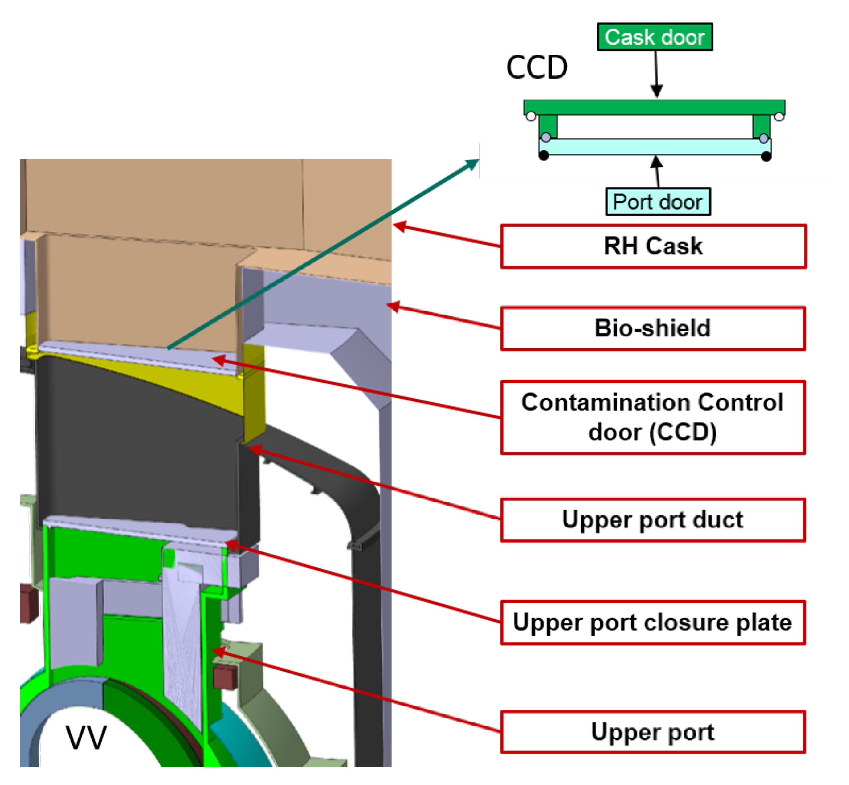
As the in-vessel components are activated and contaminated with activated dust and tritium during plasma operation [3,4], the handling and transfer of these hazardous components and materials must be performed in a contamination-controlled way meeting the safety requirements for DEMO. Thus, a system of sealed and remote handling (RH) casks is developed to confine and handle these components during their transportation between the reactor and the maintenance facility [5]. Figure 1 shows an RH cask docking to the upper port duct. There are also several equatorial ports and lower ports for access to in-vessel components in DEMO [6,7].
In order to limit the release of activated dust and tritium during docking and undocking of the RH casks to the vacuum vessel ports and during the transfer of activated components from the vacuum vessel (VV) to the RH casks, a remotely operated contamination control door (CCD) is developed as the interface between the VV port ducts and RH casks, which is marked in Figure 1 and based on the concept of the double-seal door system in ITER ([8]), while transferring the in-vessel components, the CCD will be lifted as shown in Figure 2.
In this paper, the proof of principle design of the CCD is introduced in Section 2. The operation sequences during maintenance of in-vessel components are explained step by step in Section 3. Section 4 illustrates the design of the test rig in order to evaluate the performance of high-risk components in the CCD. Section 5 gives an outlook of the possible work in the future.
2. Proof of Principle Design of CCD
The CCD is located at the interface between port ducts and RH casks. It consists of:
- Two separable doors: a cask door that can be connected with the cask; and a port door that can be connected with the port.
- Three locking mechanisms (LMs): an LM cask door-to-cask that connects/disconnects the cask door with the cask, an LM cask door-to-port door that connects/disconnects the cask door and port door and an LM port door-to-port that connects/disconnects the port door with the port duct.
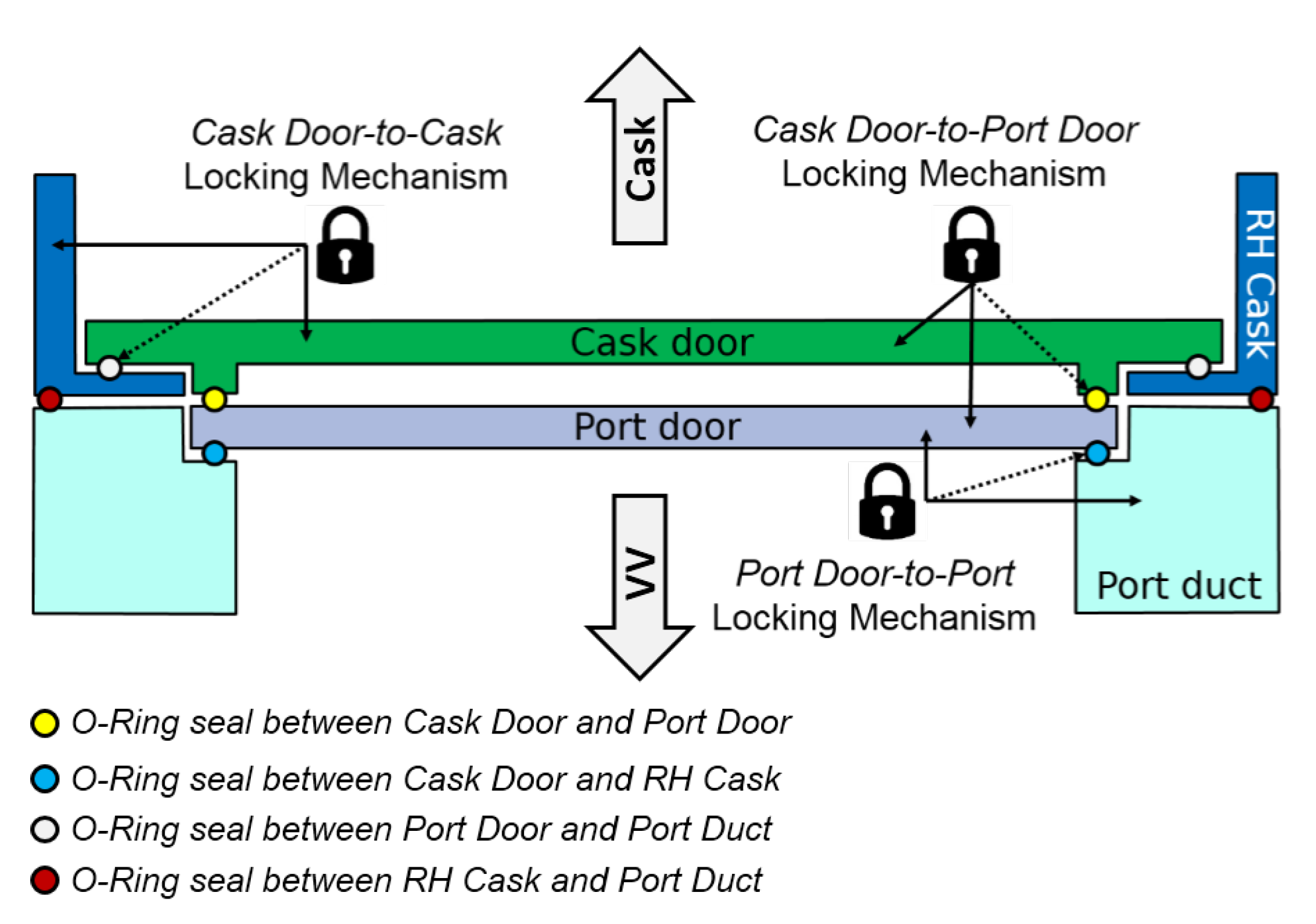
A schematic diagram of the CCD and its relevant subsystems are shown in Figure 3. The double door system allows automatic connection and disconnection of the casks to the ports in a controlled way, thereby, minimizing the risk of activated dust and tritium release to the environment during in-vessel component handling.
After docking the cask to the upper port, the cask door and the port door are connected and sealed to each other to prevent contamination of their exterior surfaces, such that the exterior surfaces remain clean after undocking the cask to the port. Furthermore, sealing is needed for confinement in the interfaces between the cask door and cask, between the cask door and port door and between the port door and poor duct. In the following subsections from Section 2.1, Section 2.2 and Section 2.3, a detailed illustration of CCD subsystems regarding the example of the upper port will be given.
2.1. Geometry of Double Doors
The development of CCDs was previously based on the DEMO 2014 baseline design [10], which had 16 ports around the VV with five blanket segments per port. The cross-section of the VV upper port duct opening was a trapezoidal shape with a surface area of around . The dimension of the RH cask opening had a similar size and shape as the upper port duct opening. The geometry model of the CCD was based on the dimensions of the upper port duct and cask opening. Figure 4a shows the geometry model of the CCD based on the DEMO 2014 baseline.
It was assumed that both doors were made of common steel and had a thickness of each. As a result, each door had a weight of about . By the end of 2015, a new baseline was agreed upon [11], in which the VV is divided into 18 vertical ports in the toroidal direction, rather than 16. The modification of the DEMO baseline has reduced the size of upper ports, which results in a change in the size of the CCD.
The updated geometry model of a CCD is shown in Figure 4b, and the material of the doors is still common steel. With help of the Abaqus Topology Optimization Module (ATOM), the topology and shape optimization is performed, while leveraging advanced simulation capabilities, such as contact, material nonlinearity and large deformation [12]. This is a mathematical approach that optimizes the material layout within a given design space for a given set of loads and boundary conditions such that the resulting layout meets a prescribed set of performance targets.
Compared to the old model, the ATOM has removed volume (material) in the front and the rear part of the door, where the deflection is expected to be small. On the other hand, in the central area of the model, where larger deformations are expected, there is a higher accumulation of material and increased thickness of the door. For the purpose of easy manufacture, the structural ribs are used as stiffeners in the central area. The finite element method is used during the structural design of doors to control the deformation of doors under dead loads. In the new CCD model, the average thickness of each door is about , and the weight is reduced to about , while the stiffness of the door is increased compared to the previous design.
2.2. Sealing
The CCD consists of several seals for confinement and preventing the release of active dust as marked by small circles in Figure 3. The positions of sealing are between the cask door and port door, between the cask and cask door as well as between the port door and port duct. In order to select the most appropriate sealing type, the required compression force to guarantee reliable tightness, the repeatability, cost and maintainability of sealing should be considered. The elastomer O-ring sealing has a round/O-shaped cross-section and is made of nitrile butadiene rubber (NBR), silicone rubber or fluorine (Viton). It requires low compression force and may be reused many times, which results in a low cost.
Thus, it is appropriate sealing for use in the CCD. However, as the port door-to-port duct sealing should remain in the upper port duct over the period of reactor operation, it has to withstand high irradiation. The maximum radiation dose limit of rad-hard elastomer seals is about 10 MGy [13]. If the accumulated total dose exceeds this value, alternative sealing material, such as metal, should be chosen. In this paper, the sealing chosen for CCD is a NBR O-Ring with 50 Shore A hardness and a diameter of . It requires for 20% compression, which is about compression force for use between the cask door and port door, whose circumference is approximately .
2.3. Locking Mechanisms
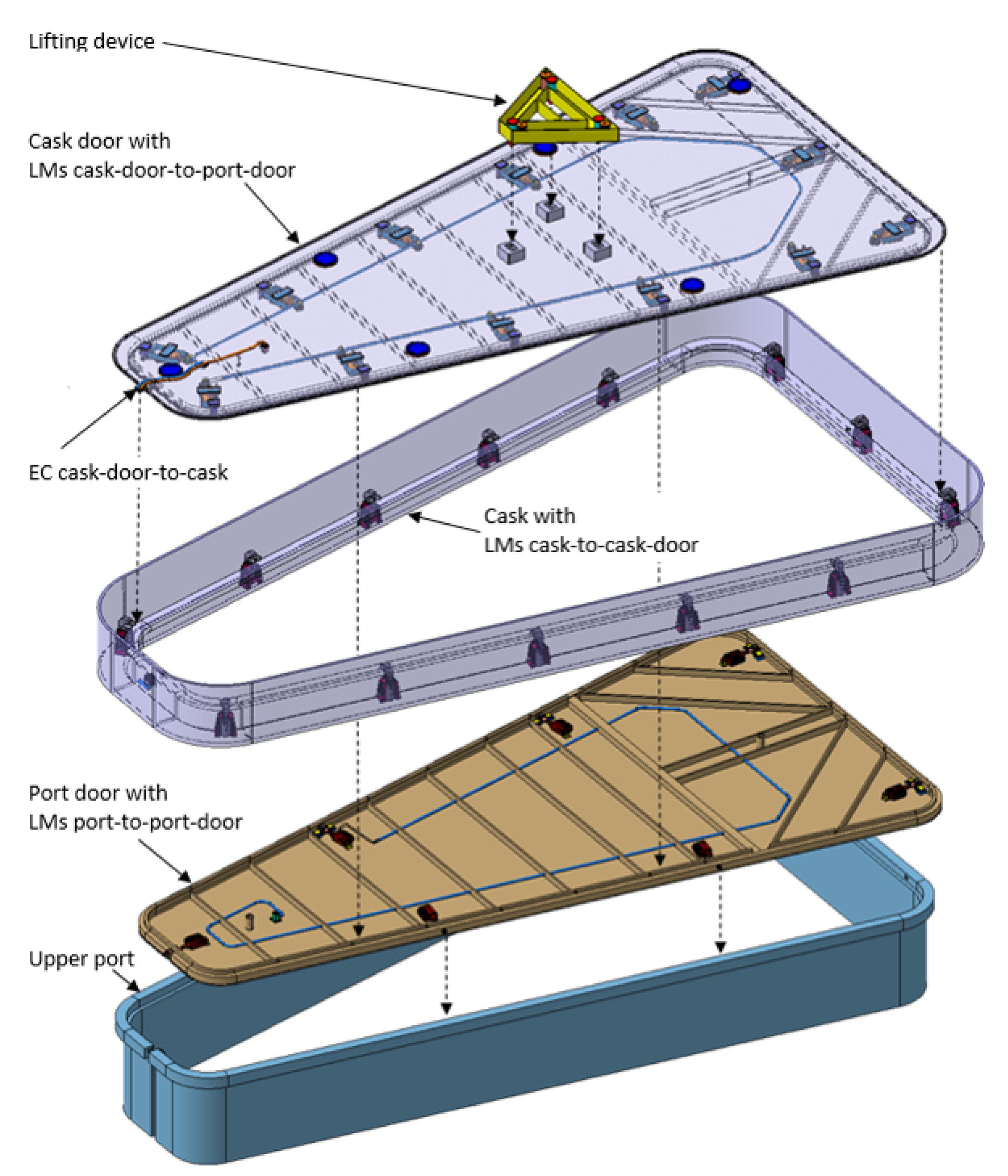
The three locking mechanisms in a CCD should be able to offer sufficient clamping force to satisfy the requirement of 20% compression of sealing taking the own weight and the weight of doors into account. The calculation of clamping forces is shown in Table 1. The LMs are distributed uniformly along the circumference of the doors as the sealing. Figure 5 shows the separated CCD with part of the cask and port duct. The LMs cask door-to-cask is installed inside the RH cask, where the power supply comes from. The LMs cask door-to-port door is installed on the cask door, while the LMs port door-to-port is installed on the port door.
All the LMs are driven by electric actuators independently (decentralized). The decentralized actuation has the advantage that, if one of the LMs fails, the proper function of the entire mechanism is not directly affected; the rest of the LMs remain intact and can further perform operations. Electric actuators have some advantages in comparison to hydraulic or pneumatic actuators. For example, they require less space for their installation, and they can be operated and controlled easily.
Furthermore, they require less maintenance by offering high accuracy at the same time. In addition, there is no risk of leakage of hydraulic or pneumatic fluid during operation. The materials of the main components in the LMs are steel and aluminum. LM cask door-to-casks and LM cask door-to-port doors are only used during the maintenance period, as the radiation has less effect on these components. However, the port door closes and seals the upper port duct opening over the period of reactor operation and should be able to withstand a certain amount of gamma and neutron irradiation.
Thus, the material of the LM port door-to-port should be carefully selected, and the chosen component may be customized; however, this is out of the scope of this paper. In the following paragraphs from Section 2.3.1, Section 2.3.2 and Section 2.3.3, the individual locking mechanisms will be introduced.
2.3.1. LM Cask Door-to-Cask
The locking mechanism for a connection between the cask door and cask is the electric-driven clamp with a lever arm. The schematic description of the clamping unit is shown in Figure 6. The LM cask door-to-cask is composed of an electric clamp, lever arm and the support frame for mounting the assembly to the cask. The electric clamp (Tuenkers EK 80.1, [14]) is capable of providing a maximum clamping moment of . It consists of a standard DC motor mounted to a trapezoidal threaded spindle that transmits the power to the toggle mechanism. In the case of power loss, the self-locking capability of the clamp is ensured by the trapezoidal threaded spindle.
2.3.2. LM Cask Door-to-Port Door
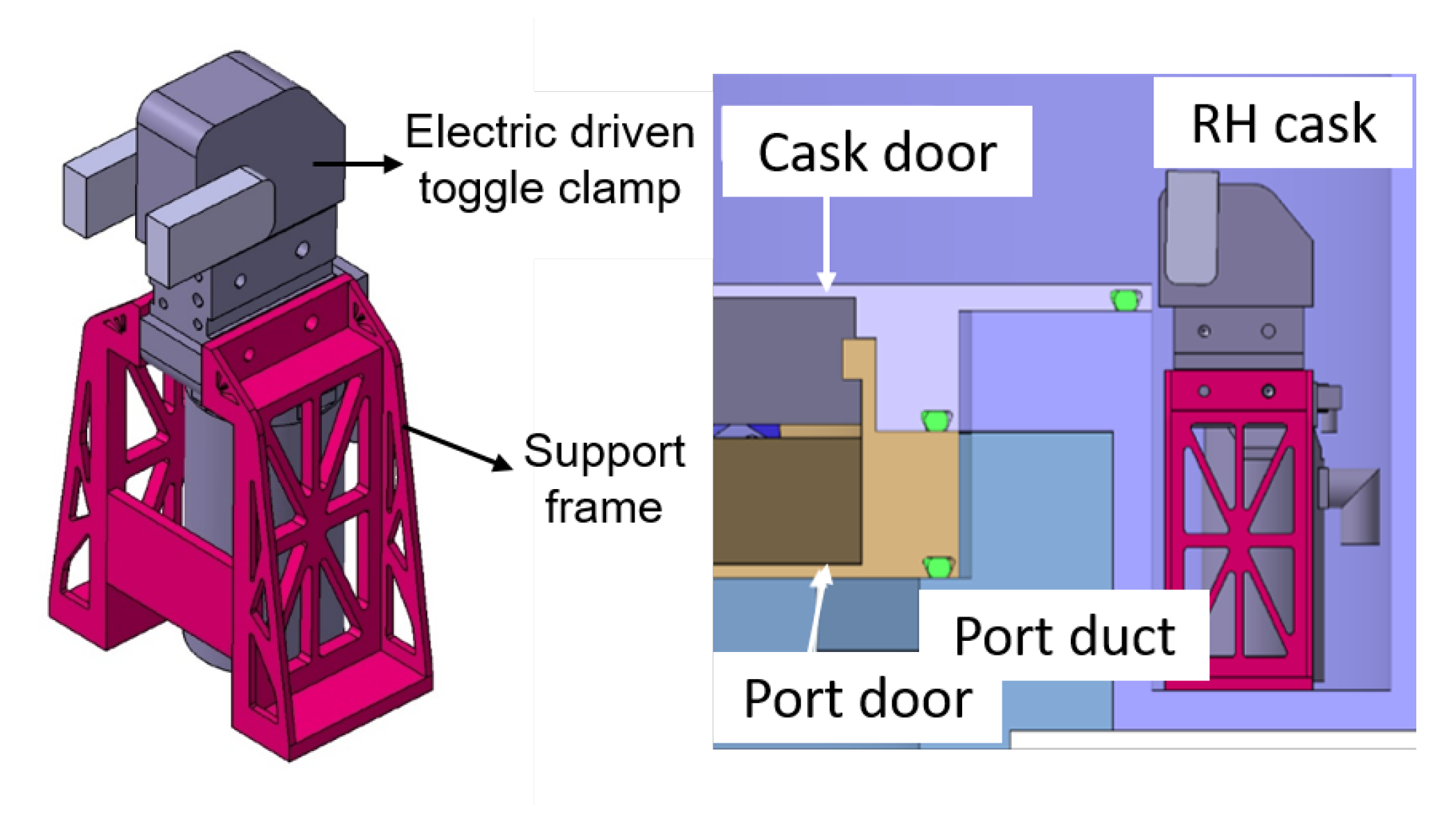
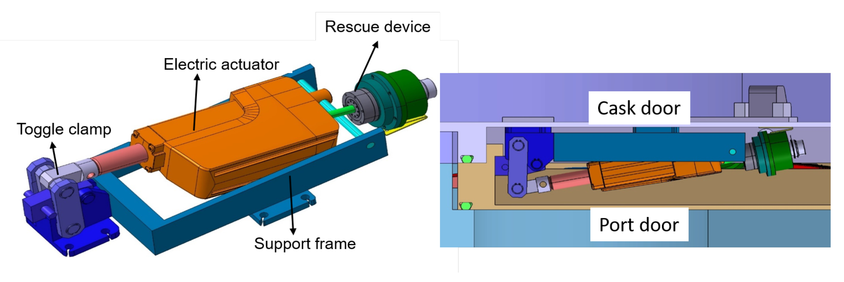
The electric driven toggle clamp is used for a connection between the cask door and port door, as shown in Figure 7. The toggle clamp is a simple mechanism based on the knee-lever principle and can provide high clamping force with little expenditure of input force. The LM cask door-to-port door consists of an electric actuator, a toggle clamp with linkages for multiplying the applied force and a base for mounting the assembly to the cask door.
The toggle clamp (AMF part No. 6960C-6, [15]) is able to exert a maximum of clamping force by an input force of without permanent structural deflection according to the manufacturer’s specifications. The electric actuator (Thomson Electrak part No.HD24B045, [16]) is able to produce a maximal dynamic load of . In the case of power loss, the self-locking capability is ensured by the Acme screw. Furthermore, it is equipped with an “emergency screw” for manual operation in both directions in the case of failure.
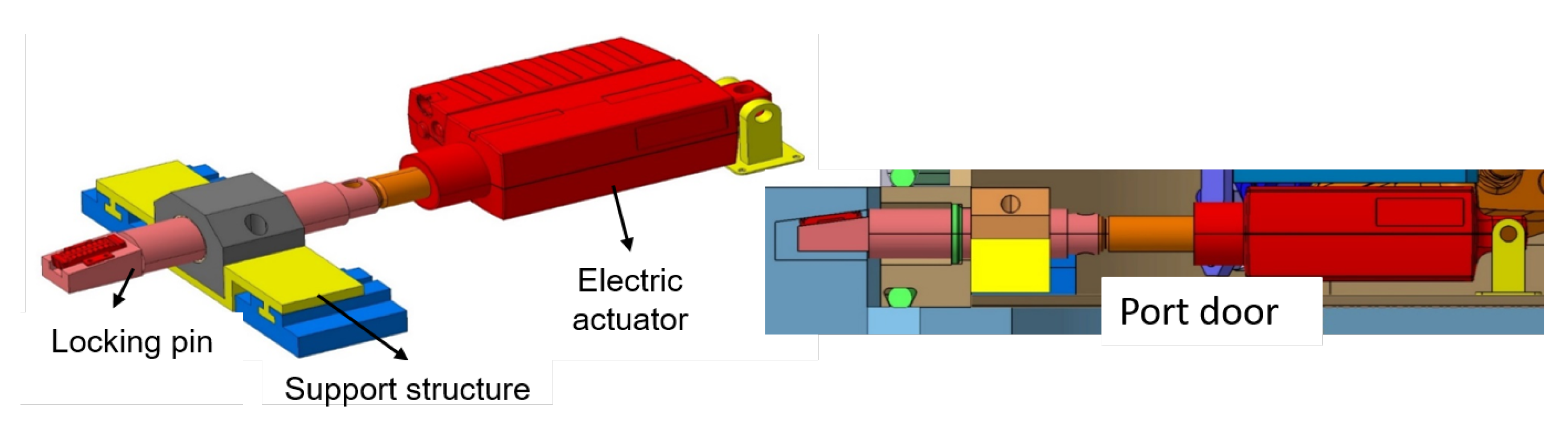
2.3.3. LM Port Door-to-Port
The locking pin driven by an electric cylinder was selected for a connection between the port door and port as shown in Figure 8. The linear actuator used is the same as in the LM cask door-to-port door (Thomson Electrak part No.HD24B045, [16]). The locking pin has a slope of 8°, which intensifies the linear actuation force generated by the actuator using the wedge effect.
The linear guiding of the locking pin and the absorption of the radial forces is provided by a sliding bearing (drylin R Part No RJUM-05-50, [17]) with a low friction coefficient of approximately . To reduce the friction between the locking pin and the port duct, a linear motion roller (Model THK LR-1547Z, [18]) is installed on the slope of the locking pin, whose friction coefficient is between and . There is also a support structure for mounting the bearing and actuator to the port door.
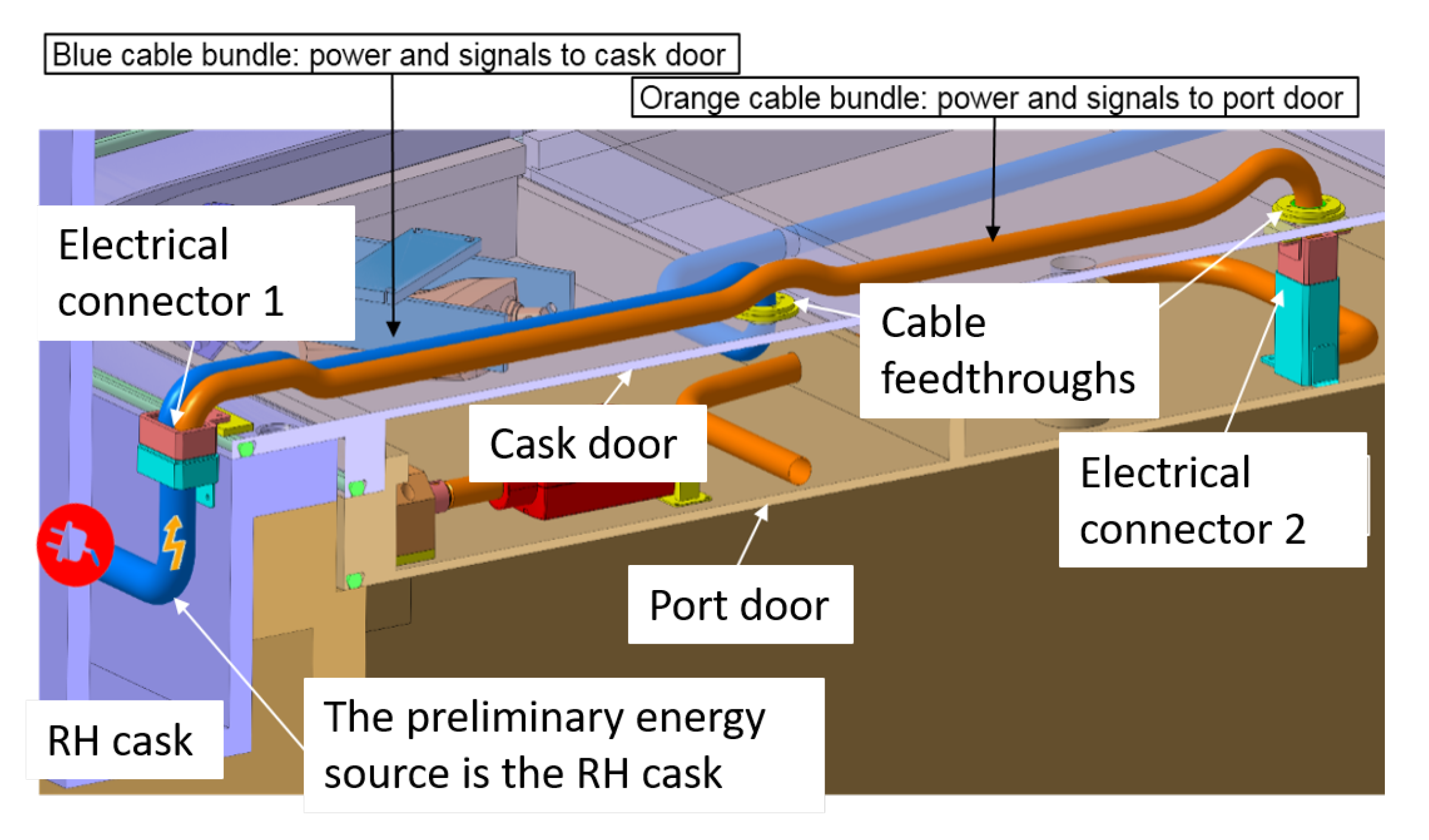
2.4. Electrical Connectors
The primary power source for LMs of CCD is from RH cask. For the transmission of the power supply and communications, electrical connectors are needed. There are two electrical connectors planned in CCDs, one between the cask and cask door and another between the cask door and port door, as indicated in Figure 9. The electrical connector 1 (between the cask and cask door) has two cable bundles, one of them is for the supply of the LM cask door-to-port door and another one is routed to electrical connector 2, which is responsible for the LM port door-to-port. As the LM cask door-to-cask is directly mounted to the cask, no electrical connector is needed.
3. Operations of the CCD
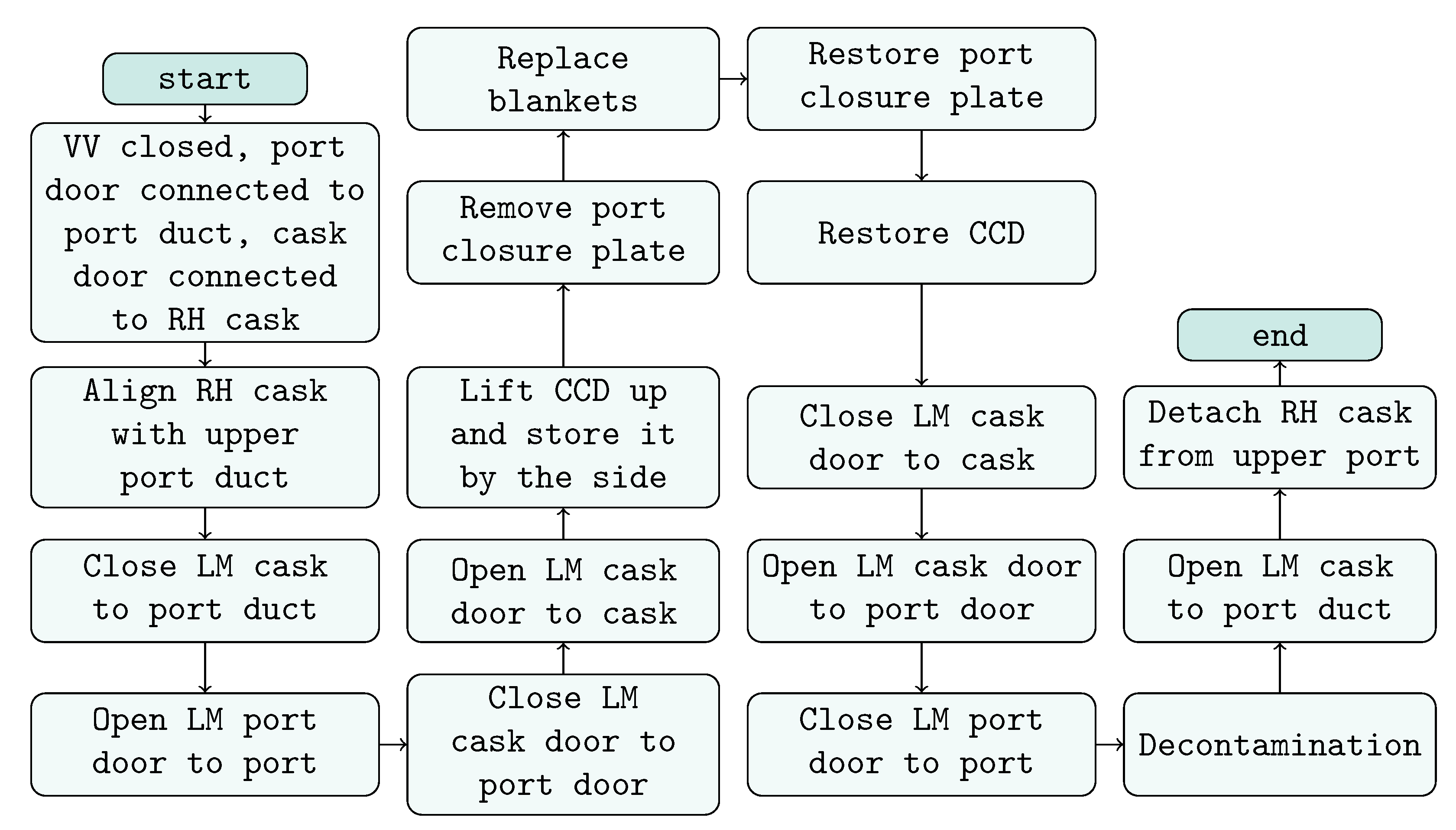
In this chapter, the detailed operation sequences for the maintenance of in-vessel components are illustrated. The opening/closing of the LMs in CCD during the whole procedure is also explained based on the example of replacing the blankets:
- The RH cask is transported to the upper port duct. During this process, the cask opening is closed and sealed with the cask door, while the upper port duct opening is closed and sealed with the port door. The two doors are separated.
- The RH cask is docked and connected to the upper port duct. Subsequently, the LM port door-to-port can be opened, after that, the LM cask door-to-port door will be closed in order to avoid counteracted force.
- After connecting the cask door with the port door, the cask door is disconnected from the cask, and the LM cask door-to cask is opened. The CCD can be lifted up and stored inside the RH cask, e.g., using a slider-guide mechanism, such as the garage door, as shown in Figure 2.
- Open the upper port by removing the upper port closure plate. Then, there is free access to the VV for maintenance operations.
- Remove the in-vessel component, such as a blanket, and store it in the cask.
- Close the upper port by restoring the upper port closure plate.
- Restore the CCD following disconnection of the cask door from the port door, connection of the cask door with the cask and connection of the port door to the upper port duct. (The LM cask door-to port door opened, and the LM cask door-to-cask and LM port door-to-port closed)
- There will remain a small contaminated area between the cask and CCD when the CCD is restored. It may need to be decontaminated before separating the cask with the port duct. The commonly used decontamination methods are vacuum cleaning or rinsing with alcohol.
- After decontamination, unlock the RH cask from the upper port duct, and the RH cask can be detached.
- Transport the RH cask with the used blanket to the maintenance facility for maintenance, e.g., decontamination.
The sequence of opening of the doors (steps 1 to 4) is illustrated in Figure 10. The closing of the doors follows the converse sequence; thus, it is not depicted.
The whole procedure can be described by the flow chart in Figure 11:
4. Test Rig
During the lifting procedure of CCD as in step 3 of Section 3, the elastic property of the doors causes bending and deflection of the structure, which has an impact on the correct positioning, attachment and locking of the CCD. In order to investigate the performance of high-risk components in the CCD in the case of deflections and malpositioning, a test rig should be designed. This chapter clarifies the purpose and the detailed design of the test rig.
4.1. Purpose
The locking mechanisms and electrical connectors have been recognized as the most critical components of the CCD according to the DFMECA (Design Failure Mode Effects and Criticality Analysis). In the case of large deflections, electrical connectors may not be paired correctly, or the pins may be deformed. The correct function of the electric connectors is crucial for the entire process because, in the case of malfunctions, the power supply of the locking mechanisms cannot be provided, and they will not be able to operate correctly. In addition, a deflection within the structure can threaten the operation of the single locking mechanism. If the deflection is too large, they may not be able to apply the required clamping force.
The performance of these critical components in the case of deflections should be investigated by test rig trials in a test rig. As deflection along three axes and three angles can occur, we aimed to design a test rig that offers the possibility to induce misalignments along the axes and angles and to identify a possible range of operation of the single component.
4.2. Test Rig Design
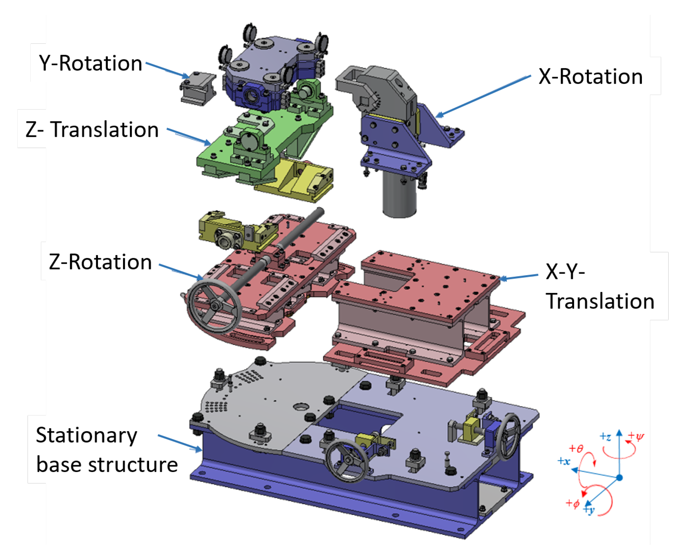
In the test rig mock-up, the performance of the locking mechanisms and electrical connectors should be investigated separately. In order to simulate the misalignments in six degrees of freedom, the test rig has to provide six main mechanisms, which allow translational and rotational adjustments of the installed test subjects. Therefore, the test rig will be separated into several modules performing the respective translation or rotation. Furthermore, the test rig should have a module plate on which the test components can be installed as well as a respective counterpart for the test components.
In addition, measurement systems have to be included for evaluating the tests and functionality of the test components, e.g., measurement of the simulated misalignment and the resulting clamping force of the LM. The test rig was designed using Autodesk Inventor, and its composition is shown in Figure 12. The functions of different modules are explained below.
- Y-rotation: The clamping force provided by the LM will be applied directly to this module; it is also the counterpart for the test components. The module consists of three plates that are guided by four bolts. The sealing has to be compressed the between both upper plates. The measurement of the clamping force is realized by three load cells (Model C9C from Hottinger Baldwin Messtechnik GmbH) installed between both lower plates. For measuring the deformation of the sealing, a magnetic-inductive distance sensor (MDS-35-M12-CA-HT from Micro Epsilon) is installed between the upper both plates. The misalignment around Y-axis will be set by a wedge profile that can be pulled out to change the angle of the plates, which has to be measured manually. In addition, several dial gauges (M3aT from PMT shop) will be installed to monitor the movement of the plates, e.g., to check if the plates move into an inclined position or stay horizontal.
- Z-translation: This module is beneath the Y-rotation module. There are four wedge profiles mounted on the underside on which counter wedge profiles can slide, which are driven by a threaded spindle in the Z-rotation module. The four wedge profiles and spindle convert the horizontal translation of the wedges into a vertical translation of the counterpart in the Z-direction.
- Z-rotation: This module contains a semicircular plate with hole patterns and the spindle for adjusting the misalignment along the Z-direction. The semicircular plate can be rotated to adjust the misalignment around the Z-axis and is guided by a bolt at the rotation center. The rotation degrees are also marked on the plate. In addition, this module contains a magnetic-inductive distance sensor (MDS-45-M18-SA from Micro Epsilon) for measuring the displacement in the Z-direction.
- X-Y-translation: This module is used to adjust the position of test objects in the X–Y-plane and is the base support structure for all LMs. The stepless adjustment of this structure is realized by two threaded spindles (one for each axis) mounted on the underlying stationary base structure. The measurement of the displacement in the X-/Y-direction is realized by two magnetic-inductive distance sensors (MDS-45-M18-SA from Micro Epsilon).
- X-Rotation: The rotation around the X-axis is realized by wedge-shaped spacer plates that are integrated in the respective support structure of every actuator. The rotation degree can be adjusted by changing the support plate of the actuator.
- Stationary base structure: All modules are installed on this structure. This module is fixed to the ground and is used to form a closed system with regard to the load transmission.
4.3. Initial Definition of the Test Program
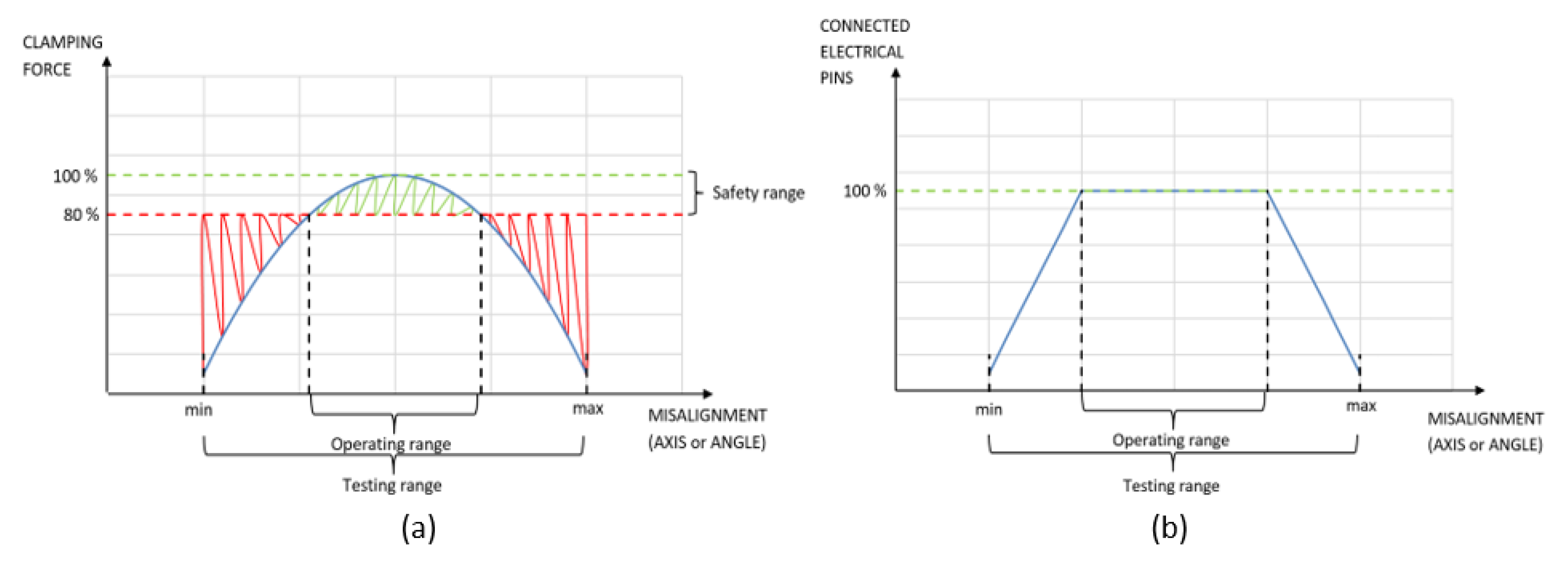
It is expected that misalignments at the CCD will be in a range of or ±1°. To cover the whole spectrum of possible relative positions between the test component and to make a secure statement about the reliability of the devices that are responsible for the required clamping force, a higher provisional range to be tested on the test rig is defined, which is or ±3°. As the performance of locking mechanisms and electrical connectors is investigated separately, the resulting clamping force of LMs or connectivity of electrical connectors should be evaluated under different misalignments. The possible range of operating can be identified by drawing the clamping force/connectivity-misalignment diagram as in Figure 13.
5. Conclusions
In this paper, the concept of a contamination control door as the interface between RH casks and vacuum vessel ports was introduced. The composition of a CCD was illustrated in detail, including the geometry of double doors, the sealing type, locking mechanisms and electrical connectors. The operations for the maintenance of in-vessel components were clarified. The high-risk components in a CCD were recognized and will be tested in the developed test rig. The introduced concept of the CCD was able to satisfy the confinement requirement during maintenance, and the proposed locking mechanisms should provide sufficient clamping force for the compression of sealing according to the calculations.
The developed test rig can simulate the misalignments in six degrees of freedom such that the high-risk components in the CCD can be validated. In the next step, the test rig will be built, and the tests will be conducted. The material for the LM port door-to-port will be analyzed due to the long time staying in the port during operation. Once the performance of a single locking mechanism and electrical connector is evaluated and an appropriate material is defined, a test facility with a scaled CCD can be designed to investigate the general function of CCDs in the future.
Author Contributions
Conceptualization, Y.W., J.O. and C.B.; Methodology, Y.W.; Writing–original draft, Y.W.; Writing–review & editing, Y.W., J.O. and M.M.; Supervision, M.M.; Project administration, M.M. All authors have read and agreed to the published version of the manuscript.
Funding
This research was funded by the European Union via the Euratom Research and Training Programme (Grant Agreement No 101052200—EUROfusion).
Data Availability Statement
Not applicable.
Acknowledgments
This work was conducted within the framework of the EUROfusion Consortium, funded by the European Union via the Euratom Research and Training Programme (Grant Agreement No 101052200—EUROfusion). The views and opinions expressed are however those of the author(s) only and do not necessarily reflect those of the European Union or the European Commission. Neither the European Union nor the European Commission can be held responsible for them. The authors acknowledge the contribution of Vladimir Madzharov to the conceptualization of this work.
Conflicts of Interest
The authors declare no conflict of interest.
References
- EUROfusion. European Research Roadmap to the Realisation of Fusion Energy. Available online: https://www.euro-fusion.org/fileadmin/userupload/EUROfusion/Documents/TopLevelRoadmap.pdf (accessed on 9 January 2023).
- Federici, G.; Bachmann, C.; Barucca, L.; Biel, W.; Boccaccini, L.; Brown, R.; Bustreo, C.; Ciattaglia, S.; Cismondi, F.; Coleman, M.; et al. DEMO design activity in Europe: Progress and updates. Fusion Eng. Des. 2018, 136, 729–741. [Google Scholar] [CrossRef]
- Taylor, N.; Ciattaglia, S.; Boyer, H.; Coombs, D.; Jin, X.Z.; Liger, K.; Mora, J.C.; Mazzini, G.; Pinna, T.; Urbonavičius, E. Resolving safety issues for a demonstration fusion power plant. Fusion Eng. Des. 2017, 124, 1177–1180. [Google Scholar] [CrossRef]
- Ratynskaia, S.; Bortolon, A.; Krasheninnikov, S. Dust and powder in fusion plasmas: Recent developments in theory, modeling, and experiments. Rev. Mod. Plasma Phys. 2022, 6, 1–50. [Google Scholar] [CrossRef]
- Bachmann, C.; Gliss, C.; Janeschitz, G.; Steinbacher, T.; Mozzillo, R. Conceptual study of the remote maintenance of the DEMO breeding blanket. Fusion Eng. Des. 2022, 177, 113077. [Google Scholar] [CrossRef]
- Loving, A.; Crofts, O.; Sykes, N.; Iglesias, D.; Coleman, M.; Thomas, J.; Harman, J.; Fischer, U.; Sanz, J.; Siuko, M.; et al. Pre-conceptual design assessment of DEMO remote maintenance. Fusion Eng. Des. 2014, 89, 2246–2250. [Google Scholar] [CrossRef] [Green Version]
- Bachmann, C.; Ciupinski, L.; Gliss, C.; Franke, T.; Härtl, T.; Marek, P.; Maviglia, F.; Mozzillo, R.; Pielmeier, R.; Schiller, T.; et al. Containment structures and port configurations. Fusion Eng. Des. 2022, 174, 112966. [Google Scholar] [CrossRef]
- Ribeiro, I.; Damiani, C.; Tesini, A.; Kakudate, S.; Siuko, M.; Neri, C. The remote handling systems for ITER. Fusion Eng. Des. 2011, 86, 471–477. [Google Scholar] [CrossRef]
- Crofts, O.; Loving, A.; Torrance, M.; Budden, S.; Drumm, B.; Tremethick, T.; Chauvin, D.; Siuko, M.; Brace, W.; Milushev, V.; et al. EU DEMO Remote Maintenance System development during the Pre-Concept Design Phase. Fusion Eng. Des. 2022, 179, 113121. [Google Scholar] [CrossRef]
- Harman, J. WP13 Reference DEMO CAD Model Specification, EFDA-2MACBZ. 2013. Available online: https://doi.org/idm.euro-fusion.org (accessed on 9 January 2023).
- Crofts, O. Integrated RM CAD Model, EFDA-2MKKTJ. 2015. Available online: https://doi.org/idm.euro-fusion.org (accessed on 9 January 2023).
- Dassaultsystems. Abaqus Topology Optimization Module (ATOM). Available online: https://www.3ds.com/fileadmin/PRODUCTS-SERVICES/SIMULIA/RESOURCES/SIMULIA-Abaqus-Topology-Optimization-Module.pdf (accessed on 9 January 2023).
- White, I.; Von, G.; Tandon, R.; Serna, L.M.; Celina, M.C.; Bernstein, R. An Overview of Basic Radiation Effects on Polymers and Glasses. Sandia Nat. Lab. 2013. Available online: https://www.osti.gov/servlets/purl/1671997 (accessed on 9 January 2023).
- TuenkersMaschinenbauGmbH. TUENKERS Electric Clamp. Available online: https://www.tuenkers.de/publish/binarydata/service/download/espanntechniken.pdf (accessed on 9 January 2023).
- AMFWerkzeugGmbH. AMF Clamping Systems. Available online: https://www.amf.de/en/products/clamping-technology/toggle-clamps.html (accessed on 9 January 2023).
- ThomsonIndustriesINC. Thomson Aktuator Electrak HD. Available online: https://www.thomsonlinear.com/de/product/HD24B045-0100ELP2NPS (accessed on 9 January 2023).
- Drylin. dryLin R Pillow Block RJUM-05. Available online: https://www.igus.com/product/1200?artNr=RJUM-05-08 (accessed on 9 January 2023).
- THK Co., Ltd. THK LM Roller. Available online: https://tech.thk.com/en/products/thkdlink.php?id=340 (accessed on 9 January 2023).
Figure 1.
A RH cask docks to the upper port duct.

Figure 2.
The CCD is lifted as a garage door for transferring in-vessel components.

Figure 3.
Schematic diagram of the CCD and its relevant subsystems [9].
Figure 3.
Schematic diagram of the CCD and its relevant subsystems [9].

Figure 4.
(a): Geometry model of a CCD based on the DEMO 2014 baseline and (b): updated geometry model of CCD from the current design.
Figure 4.
(a): Geometry model of a CCD based on the DEMO 2014 baseline and (b): updated geometry model of CCD from the current design.

Figure 5.
The distribution of LMs in the CCD.

Figure 6.
The locking mechanism between the cask door and cask.

Figure 7.
The locking mechanism between the cask door and port door.

Figure 8.
The locking mechanism between the port door and port.

Figure 9.
The electrical connectors in the CCD.

Figure 10.
The main sequence of opening the CCD. Step (1): RH cask docks with the port; step (2): Cask door and port door are connected; step (3): CCD is lifted; step (4): Port closure plate is removed.
Figure 10.
The main sequence of opening the CCD. Step (1): RH cask docks with the port; step (2): Cask door and port door are connected; step (3): CCD is lifted; step (4): Port closure plate is removed.

Figure 11.
The flow chart of operation sequences for maintenance of blanket.

Figure 12.
Modular design of the test rig assembly on the example of the LM cask door-to-cask.

Figure 13.
(a) Results to be achieved for locking mechanisms and (b) results to be achieved for electrical connectors.
Figure 13.
(a) Results to be achieved for locking mechanisms and (b) results to be achieved for electrical connectors.


Table 1.
The calculation of clamping forces.
| Units | LM Cask Door-to-Cask | LM Cask Door-to-Port Door | LM Port Door-to-Port | |
|---|---|---|---|---|
| Length of sealing | mm | 22,786 | 21,840 | 21,840 |
| Required compression force | kN | 178.2 | 170.8 | 170.8 |
| Supporting load-weight of doors | kN | 35.4 | 36.8 | 36.8 |
| Required clamping force | kN | 142.8 | 134 | 134 |
| Required clamping force with safety factor | kN | 172 | 160 | 160 |
Disclaimer/Publisher’s Note: The statements, opinions and data contained in all publications are solely those of the individual author(s) and contributor(s) and not of MDPI and/or the editor(s). MDPI and/or the editor(s) disclaim responsibility for any injury to people or property resulting from any ideas, methods, instructions or products referred to in the content. |
© 2023 by the authors. Licensee MDPI, Basel, Switzerland. This article is an open access article distributed under the terms and conditions of the Creative Commons Attribution (CC BY) license (https://creativecommons.org/licenses/by/4.0/).
Share and Cite
MDPI and ACS Style
Wang, Y.; Oellerich, J.; Baars, C.; Mittwollen, M. Concept of Contamination Control Door for DEMO and Proof of Principle Design. J. Nucl. Eng. 2023, 4, 228-240. https://doi.org/10.3390/jne4010018
AMA Style
Wang Y, Oellerich J, Baars C, Mittwollen M. Concept of Contamination Control Door for DEMO and Proof of Principle Design. Journal of Nuclear Engineering. 2023; 4(1):228-240. https://doi.org/10.3390/jne4010018
Chicago/Turabian StyleWang, Yan, Jan Oellerich, Carsten Baars, and Martin Mittwollen. 2023. "Concept of Contamination Control Door for DEMO and Proof of Principle Design" Journal of Nuclear Engineering 4, no. 1: 228-240. https://doi.org/10.3390/jne4010018