Article

Geochemical Effects on Storage Gases and Reservoir Rock during Underground Hydrogen Storage: A Depleted North Sea Oil Reservoir Case Study

1
School of Engineering, University of Aberdeen, Aberdeen AB24 3UE, UK
2
BatiGea Ltd., Aberdeen AB25 3QN, UK
*
Author to whom correspondence should be addressed.
Hydrogen 2023, 4(2), 323-337; https://doi.org/10.3390/hydrogen4020023
Submission received: 28 February 2023 / Revised: 5 May 2023 / Accepted: 15 May 2023 / Published: 18 May 2023
(This article belongs to the Topic Hydrogen Generation, Storage, and Utilization)

Abstract

:
In this work, geochemical modelling using PhreeqC was carried out to evaluate the effects of geochemical reactions on the performance of underground hydrogen storage (UHS). Equilibrium, exchange, and mineral reactions were considered in the model. Moreover, reaction kinetics were considered to evaluate the geochemical effect on underground hydrogen storage over an extended period of 30 years. The developed model was first validated against experimental data adopted from the published literature by comparing the modelling and literature values of H2 and CO2 solubility in water at varying conditions. Furthermore, the effects of pressure, temperature, salinity, and CO2% on the H2 and CO2 inventory and rock properties in a typical sandstone reservoir were evaluated over 30 years. Results show that H2 loss over 30 years is negligible (maximum 2%) through the studied range of conditions. The relative loss of CO2 is much more pronounced compared to H2 gas, with losses of up to 72%. Therefore, the role of CO2 as a cushion gas will be affected by the CO2 gas losses as time passes. Hence, remedial CO2 gas injections should be considered to maintain the reservoir pressure throughout the injection and withdrawal processes. Moreover, the relative volume of CO2 increases with the increase in temperature and decrease in pressure. Furthermore, the reservoir rock properties, porosity, and permeability, are affected by the underground hydrogen storage process and, more specifically, by the presence of CO2 gas. CO2 dissolves carbonate minerals inside the reservoir rock, causing an increase in the rock’s porosity and permeability. Consequently, the rock’s gas storage capacity and flow properties are enhanced.

1. Background

The current energy transition is defined as the process of moving from conventional fossil fuels to sustainable and renewable energy resources, such as solar and wind energies. This energy transition is motivated by different factors, the most important of which are climate change and energy sustainability. It is expected that hydrogen energy will play a vital role in this transition [1,2,3,4].
Hydrogen is a clean burning fuel that can be used to generate energy for vehicles, heating, and electricity. One of the best characteristics of using hydrogen as a fuel is that when it is burnt, it does not generate any carbon dioxide, and the only by-product is water vapour. Hydrogen can be produced through steam–methane reforming, which is the most common hydrogen production technique. This is carried out by reacting natural gas with steam to produce hydrogen and carbon dioxide. However, this technique is not sustainable as it requires natural gas to generate hydrogen. Another technique to produce hydrogen is electrolysis, in which electricity is used to separate hydrogen and oxygen molecules in water. This technique can be powered by the excess energy produced from renewable energy sources, which makes it more sustainable compared to steam–methane reforming [5,6,7].
To achieve a sustainable future, the deployment of a hydrogen economy is essential, and for that, efficient and cost-effective hydrogen storage solutions are necessary. The hydrogen gas produced from the techniques mentioned above can be stored during high-supply periods and reused during high-demand periods, either above-ground or underground. However, above-ground hydrogen storage in vessels is limited in capacity and safety, making underground hydrogen storage an attractive alternative. Large-scale hydrogen storage is possible with underground storage in aquifers, salt caverns, and depleted hydrocarbon reservoirs, making it a feasible option for supporting widespread hydrogen adoption as an energy source [8,9,10]. Additionally, underground storage mitigates the risk of hydrogen gas leaks, reducing associated risks compared to above-ground storage options.
The use of appropriate geological formations, such as aquifers, salt caverns, or depleted natural gas or oil reservoirs, can enable cost-effective storage of hydrogen. However, UHS techniques have some challenges as experience in this technology is scarce [9,11]. In addition to geological, technical, and economic difficulties, legal and societal interplay contributes to its overall success [12,13]. The availability of suitable geological sites is crucial to the feasibility of underground storage. Furthermore, information on the depth and storage capacity of the potential site is vital as it can affect the UHS operation [10]. The understanding of the fluid–fluid and solid–fluid interactions inside the storage formation helps to plan for an efficient UHS process. Seismic activities are also an important safety concern relating to UHS because they could compromise the integrity of storage structures [10]. Economically, the efficient and effective application of underground hydrogen storage is believed to be able to unlock hydrogen energy’s competitiveness in the energy market in the near future [14]. Therefore, it is essential to ensure all technical, economic, and legal aspects are put into perspective for an effective adaptation of UHS operations.
Several research studies have been carried out to investigate the technical aspects of storing hydrogen gas underground. These aspects include hydrodynamics, geochemistry and geomechanics. Hydrodynamics in underground hydrogen storage (UHS) is concerned with studying how the hydrogen gas and fluids flow inside the porous media within the underground storage site. It also studies the geological formation’s storage capacity of hydrogen gas during its injection and its recovery efficiency during its withdrawal [8,15,16]. Several parameters can affect this hydrodynamic aspect, which can be categorized into two categories: reservoir-related parameters, and operational parameters. The reservoir-related parameters can be reservoir porosity, permeability, and pressure, among other parameters. As for the operational parameters, hydrogen gas injection and withdrawal rates, storage cycles, and several operation wells affect the underground hydrogen storage operation [17]. The injection of CO2 in the subsurface geoformations has been practised in various forms, such as CO2-enhanced oil and gas recovery [18] and CO2 sequestration as gas hydrates, alone or combined with methane–CO2 replacement, in natural gas or methane hydrate reservoirs [19,20] in an effort to meet the decarbonization targets of the leading industrial sectors. In our scheme, CO2 injections also contribute, to some extent, to these efforts while working as a cushion gas.
During UHS, geochemical interactions involving the hydrogen gas that has been stored, cushion gas, reservoir fluids, and reservoir minerals may take place [21]. Due to the conversion of hydrogen to other gases, such as methane and hydride sulphide, these processes may result in losses in the stored hydrogen. Additionally, due to interaction with other gases in the reservoir, geochemical processes have the potential to reduce the purity of hydrogen gas [22,23]. A change in the porosity and permeability of the geological structure as a result of mineral dissolution or precipitation is another significant potential consequence of the geochemical activity of hydrogen gas during UHS. As a result, the geomechanical characteristics of the geological structure can change, increasing the likelihood of structural collapse or faulting and decreasing the integrity of the cap rock [10,24]. Abiotic or biotic processes might result in geochemical reactions during UHS. Abiotic processes take place when hydrogen interacts with non-living objects such as rock minerals, oil, gas, and brine. Aqueous reactions and mineral dissolution/precipitation reactions are examples of abiotic processes [21,24]. One of the important factors that must be taken into account during UHS is hydrogen biotic reactions brought by microbial activity. The quantity and kind of live microorganisms (such as bacteria) present within the storage location controls these responses. Methanogenesis, acetogenesis, sulphate reduction, and iron reduction are some of the known biotic activities that use hydrogen. Methanogenesis is the conversion of hydrogen to methane and water when reacting with CO2 in the presence of methanogens. It is also known as the Sabatier reaction and is as follows [25]
CO 2 + 4 H 2       CH 4 + 2 H 2 O
Acetogenesis is another type of biotic reaction that takes place between H2 and CO2 in the presence of acetogen bacteria. This reaction produces acetic acid and water as follows [26]
2 CO 2 + 4 H 2       CH 3 COOH + 2 H 2 O
When sulphate-reducing bacteria are present, the sulphate reduction processes convert H2 and sulphate to hydrogen sulphide (H2S). Although they have been observed to be active in temperatures as high as 110 °C, sulphate-reducing bacteria are most active when the temperature is approximately 38 °C [27,28,29]. It is anticipated, however, that in acidic aqueous and depleted hydrocarbon reserves, particularly in the presence of high salinity brine, its action will be slower [30].
SO 4 2 + 5 H 2       H 2 S + 2 H 2 O
Amid et al. [31] and Hemme et al. [24] investigated the effects of geochemical and biochemical reactions on hydrogen storage in depleted natural gas and sandstone reservoirs, respectively. Their results suggested that sulphate reduction poses a greater challenge to the UHS process than methanation, but the overall hydrogen loss due to dissolution was less than 0.1%. The modelled UHS case was found to be capable of providing 42% of the energy capacity supply compared to the Rough Gas Storage Facility (UK), indicating that UHS can be a viable option for energy storage.
Laban [32], Bo et al. [22], and Zeng et al. [33,34], also studied the effects of various factors, such as temperature, pressure, mineralogy, and brine properties, on hydrogen storage and loss. Laban [32] found that bacteria growth rate, sulphate concentration, and cavern pressure and temperature are the most influential factors on hydrogen sulphide production through sulphate-reducing bacteria. Bo et al. [22] suggested that sandstone reservoirs are better for hydrogen storage than carbonate reservoirs because the water uptake of hydrogen does not react with quartz and clay minerals. Zeng et al. [34] studied hydrogen loss, mineral dissolution, and water chemistry over a long period of time and found that the Majiagou formation is a good candidate for UHS. Zeng et al. [33] evaluated the effects of various reservoir parameters on the wettability of a hydrogen–brine–calcite system and found that increasing the temperature and decreasing the salinity increase the disjoining pressure within the system, resulting in higher hydrogen gas repulsion from the calcite surface and increasing water wettability.
The results of Amid et al. [31] and Hemme et al. [24] suggested that hydrogen loss due to geochemical reactions and diffusion during UHS is negligible; however, Bo et al. [22] and Zeng et al. [34] found that hydrogen loss can be significant, up to 9.5% and 81.1%, respectively, depending on the storage period and reservoir mineralogy and conditions. The difference in predicted hydrogen losses might be a result of considering hydrogen-redox-coupled pair reactions, which accelerate hydrogen solubility and loss, as is the case in the work of Bo et al. [22] and Zeng et al. [34], in contrast to Amid et al. [31] and Hemme et al. [24]. The presence of calcite in the geological structure was found to lead to changes in the rock’s porosity and permeability, affecting the reservoir’s storage capacity and flow properties. Furthermore, hydrogen loss due to geochemical reactions and diffusion is directly related to both pressure and temperature, where an increase in pressure and temperature causes a rise in the hydrogen lost during UHS [24].
In this study, we investigate the effects of geochemical activities during underground hydrogen storage in a depleted North Sea oil reservoir on the stored hydrogen gas as well as the reservoir rock properties. The impact of the geochemical reactions on both reservoir’s porosity and permeability is evaluated. These evaluations will be carried out under varying pressures, temperatures and salinities to reflect potential conditional changes during the underground hydrogen storage in the targeted sandstone formation in a depleted North Sea oil reservoir. Outcomes from this study should provide valuable information for understanding the geochemical effects of underground hydrogen storage in a depleted oil reservoir to be considered during the design process.

2. Methodology

The investigations in this study are carried out using the geochemical software PhreeqC [35]. It has been previously used to quantify geochemical reactions inside oil reservoirs for different enhanced oil recovery applications [36,37,38,39]. The developed model considers equilibrium reactions, mineral dissolution/precipitation reactions, and exchange reactions. Equilibrium and exchange reactions are assumed to be fast and instant reactions and are not affected by the time of H2 and CO2 storage. The mineral dissolution and precipitation reactions are dependent on reaction kinetics and the speed of reaction. These reactions usually occur over a prolonged period time and result in changes in both the mineral and aqueous phases over time. Methanisation and sulphate reduction reactions are both biotic reactions, which are dictated by certain types of bacteria. The methanisation bacteria was reported to be active at temperatures up to 122 °C and salinities up to 3.4 mol/L. Sulphate-reducing bacteria can operate in temperatures up to 113 °C and 1.7 M NaCl [30]. These limiting values of temperature and salinity for both methanisation and sulphate reduction reactions are close to the conditions encountered inside the targeted depleted oil reservoirs. Hence, both methanisation and sulphate reduction reactions are expected to have minimal effects on the underground hydrogen storage process and are, therefore, ignored in our modelling. The mineral reactions adopted in this work are detailed in Table 1.
Mineral dissolution and precipitation reactions cause changes in the mineral phases present inside the reservoir and accordingly affect the overall rock porosity and permeability [10]. Changes in porosity as a result of rock dissolution and precipitation are determined using solid and pore volume calculations. Porosity of the rock , can be calculated as follows:
= V p V s + V p
where V p is the pore volume, and V s is the solid (rock) volume. The changes in porosity arise as a result of the rock dissolution and precipitation due to mineral reactions as modelled in PhreeqC. The porosity change affects the reservoir’s storage capacity of the reservoir rock. These changes in porosity consequently alter the permeability of the reservoir rock influencing the rock’s flow properties, and the gas injection and withdrawal process. The changes in permeability are determined using the widely used Carman–Kozeny equation as a function of the reservoir’s porosity:
k x = d p 2 3 300 1 2
where k x is the permeability (cm), is the porosity, and d p is the average diameter of sand grains (cm). Although the Carman–Kozeny equation assumes a uniform and isotropic pore geometry, we use the equation to quantify the change in permeability as a function of the original and altered porosity in the form of equation (6):
Δ k % = k 2 k 1 k 1 = 100 × 2 3 1 2 2 × 1 1 2 1 3 1 %
where k 1 and k 2 are the original and altered permeability (cm), respectively. 1 and 2 are the original and altered porosity, respectively.

2.1. Base Scenario

The simulated scenario is based on storing hydrogen gas in a depleted North Sea oil reservoir and, more specifically, in the Etive sandstone formation. Hydrogen gas is assumed to be stored with 95% of the reservoir’s working capacity and the remaining 5% is filled with CO2 as a cushion gas. The mineralogy of Etive formation plays an important role in dictating the geochemical reactions that take place during the UHS process and is detailed in Table 2. The brine salinity from the formation is shown in Table 3. In this work, we investigate the geochemical effects during underground hydrogen storage in the depleted oil reservoir on the storage gases and reservoir rock properties over 30 years. The reservoir was initially at 400 atm and 100 °C temperature. However, after depletion, the reservoir pressure dropped to 135 atm.

2.2. Sensitivity Analysis

The sandstone reservoir is assumed to have an initial pressure around 400 atm, 100 °C, and 0.5 M NaCl salinity. These conditions represent the base case values of the carried-out analysis. The sensitivity range of pressure is between 100 atm, just below the current depleted reservoir pressure, and 500 atm, the formation’s fracture pressure. The temperature range is between 80 and 120 °C to reflect any possible temperature changes inside the reservoir due to gas injection and production. The current formation’s water salinity is approximately 0.5 M, which is also the minimum in the salinity range in the sensitivity analysis. The maximum investigated salinity was 5 M. In this study, the effects of possibly varying conditions, i.e., temperature, pressure, salinity, and CO2% as a cushion gas on H2 and CO2 solubility, and rock properties (porosity and permeability) over 30 years. A summary of the base case values and range of parameters investigated are detailed in Table 4.

3. Results and Discussion

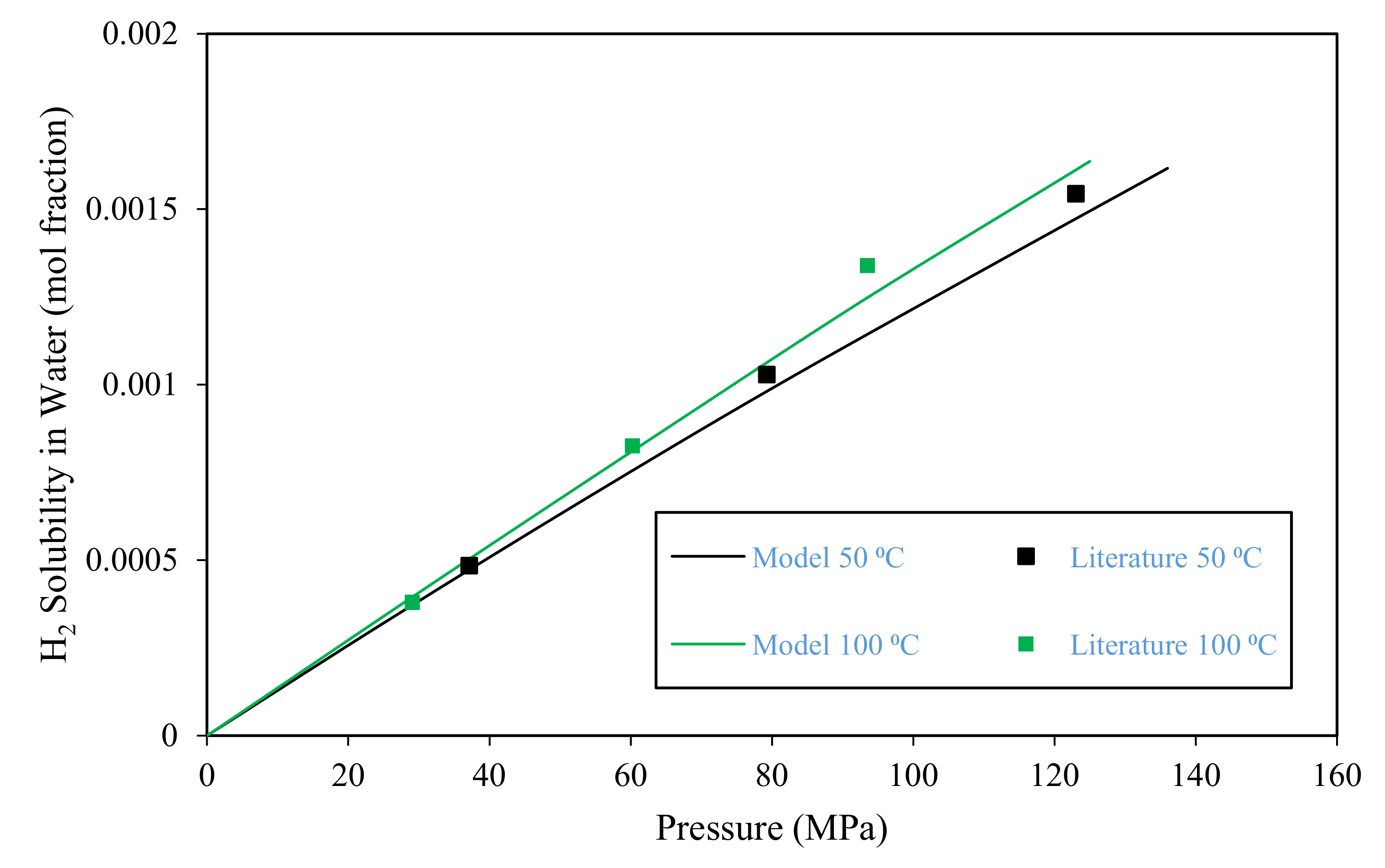
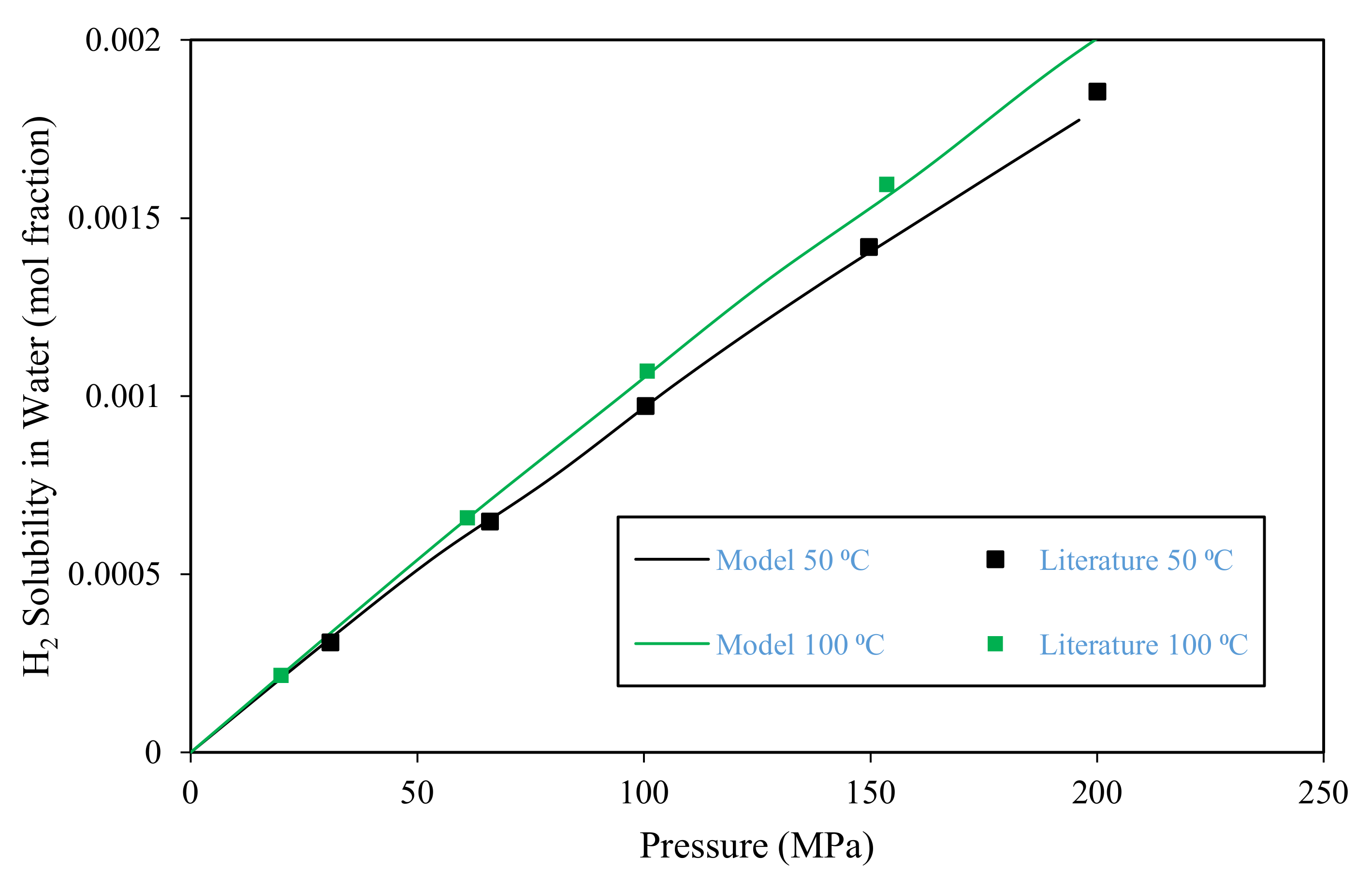
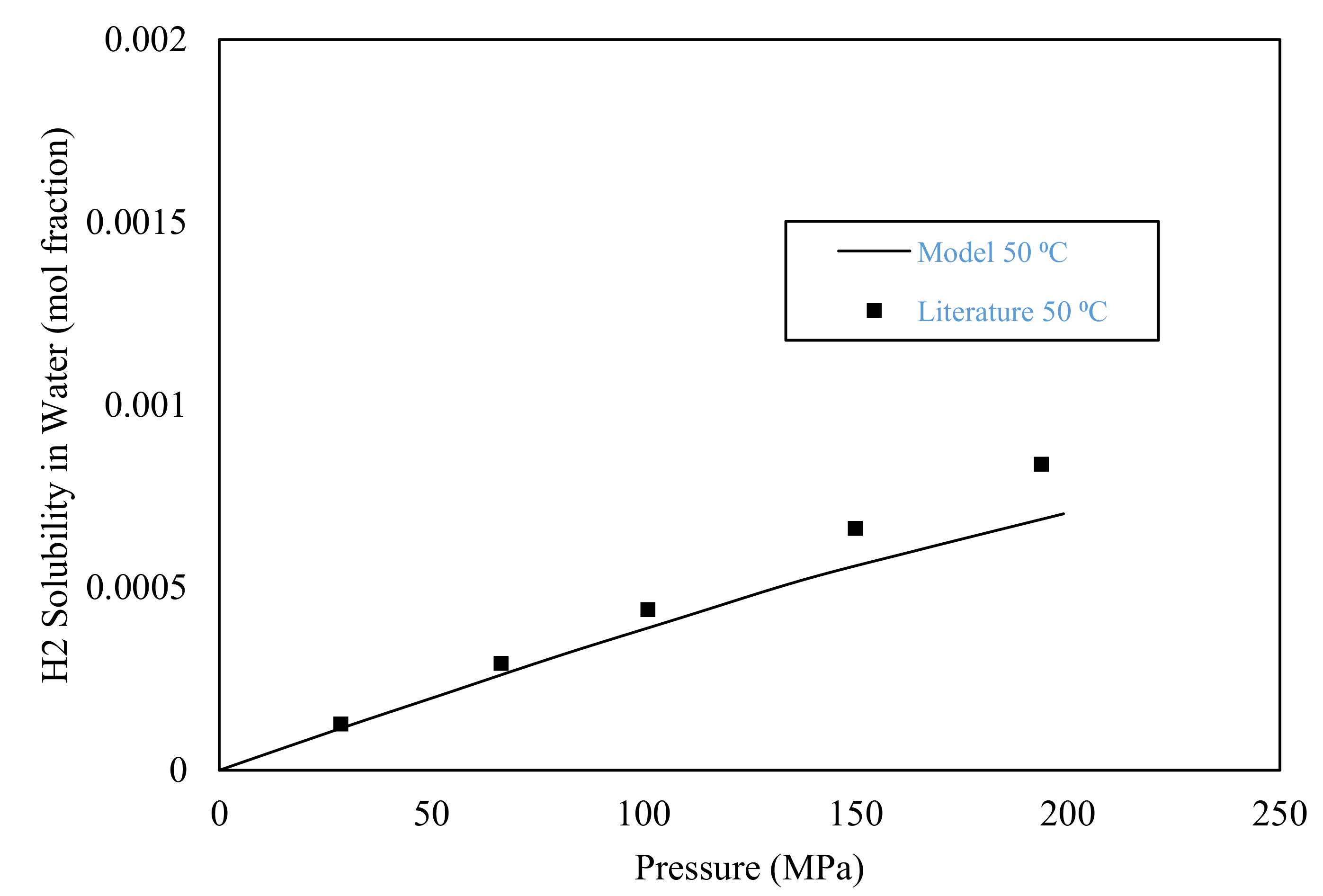
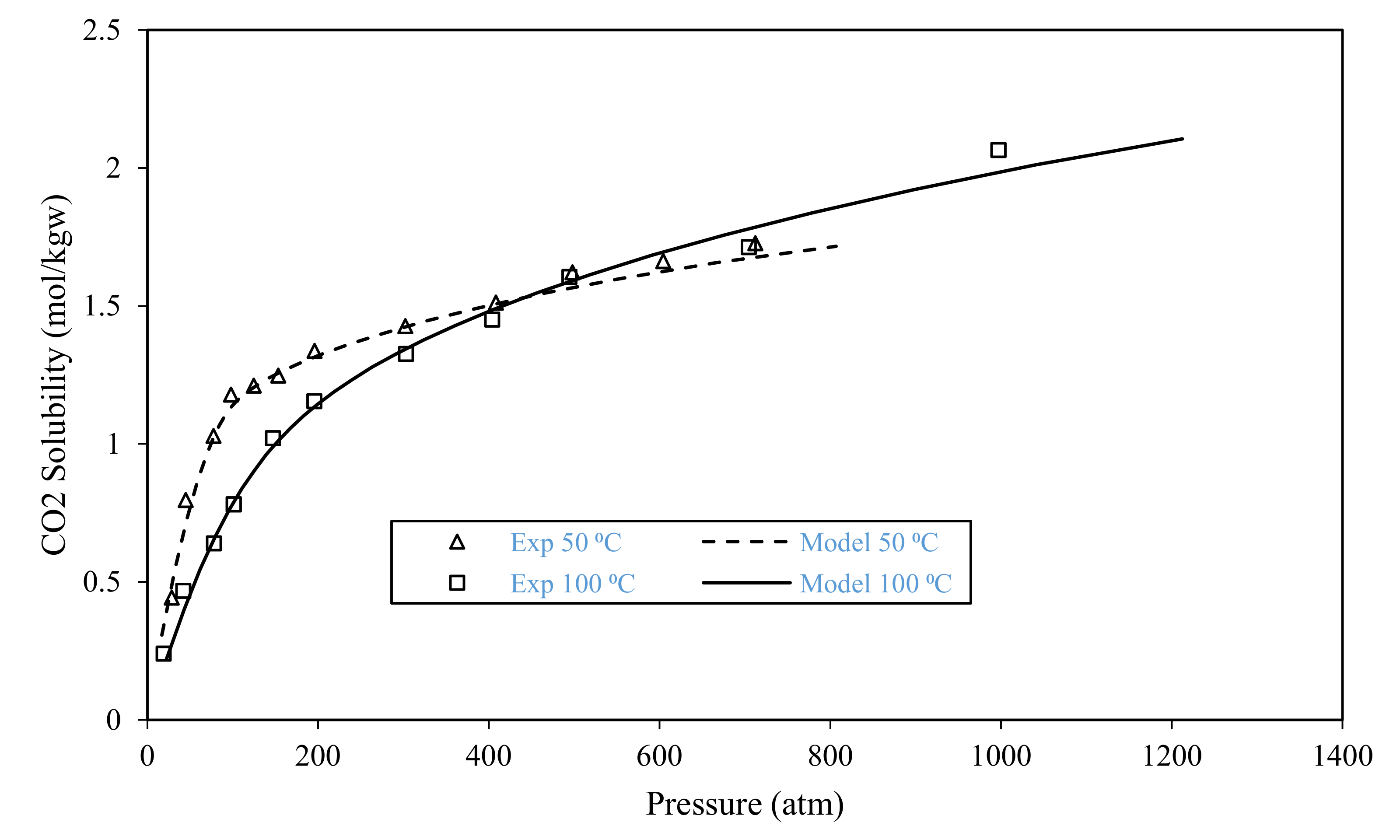
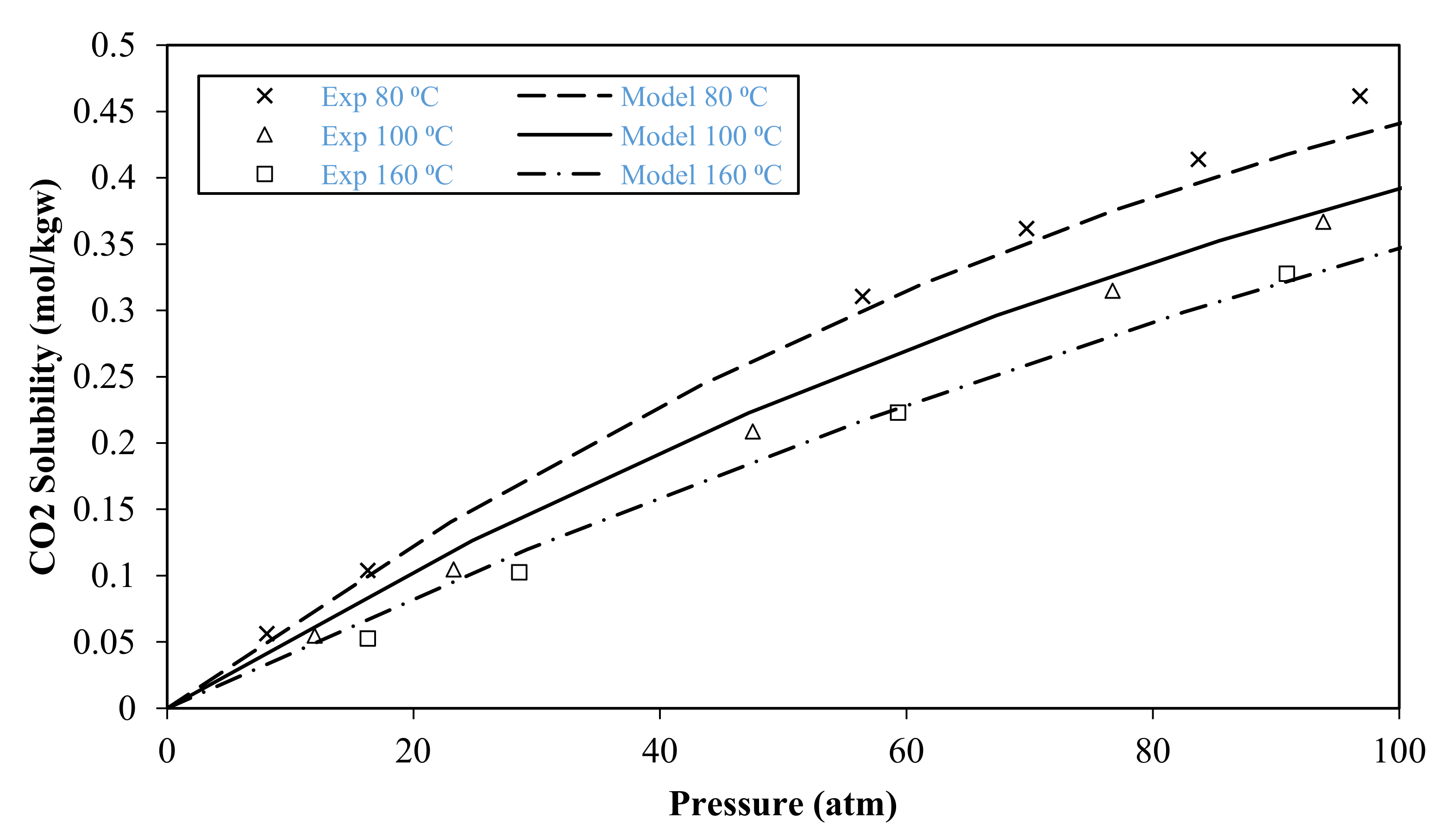
3.1. Model Validation

The developed model was validated using the H2 and CO2 solubility in water predicted from the model against experimental values reported in the literature. The validation was performed using gas solubilities at a varying range of conditions, i.e., 0–200 MPa pressure, 50–100 °C temperature, and 0–5 M NaCl salinity. The model validation is limited to gas solubility in bulk water. The gases solubility in water inside porous media is affected by the presence of rock minerals because geochemical reactions affect gas solubility.
The model-predicted H2 solubility in brine was validated against the experimental data from Chabab et al. [41]. Figure 1 shows a comparison between the modelling results and literature data for H2 solubility in pure water at 50 °C and 100 °C. The comparison shows that the model gave accurate predictions over changing pressure and temperature. It also reflects that the increase in pressure increases the amount of hydrogen dissolved in water at both 50 °C and 100 °C. For example, the hydrogen solubility increased from 0.000485 mol fraction at 37 MPa and 50 °C to 0.001544 mol fraction at 123 MPa and 100 °C. This same trend can be observed in Figure 2 and Figure 3 where higher brine salinities of 1 and 5 M NaCl were used. Similar experimental observations were made in other studies [42]. It can also be seen that increasing the temperature from 50 to 100 °C slightly decreased the dissolved hydrogen.
The developed model was also validated by comparing the model-predicted CO2 solubility in both pure and saline water and experimental values from [43,44] at varying pressure and temperature. Figure 4 presents a comparison between the modelling results and literature data in pure water at pressures between 28 atm and 2000 atm, and at 50 and 100 °C temperatures. Figure 4 shows that the model predicted the CO2 solubility in pure water with high accuracy. The increase in pressure at a certain temperature causes an increase in CO2 solubility in water. The effect of temperature on CO2 solubility in water is dependent on the exerted pressure. At pressure below 450 atm, the increase in temperature decreases with the increasing temperature; however, this trend reverses above 450 atm, where an increase in temperature increases the solubility value. Similar observations were found in other experimental studies [45]. The model was also validated for CO2 solubility in 4 M NaCl salinity brine against experimental data as shown in Figure 5. The comparison also demonstrates the model’s ability to predict the CO2 solubility in saline water with high accuracy. Having validated the model against experimental data from the literature, the model was then expanded to include mineral reactions, exchange reactions, methanisation and kinetics. The results of the sensitivity analysis of H2 and CO2 solubility and rock properties to change in pressure, temperature, salinity, and CO2% as a cushion gas are presented.

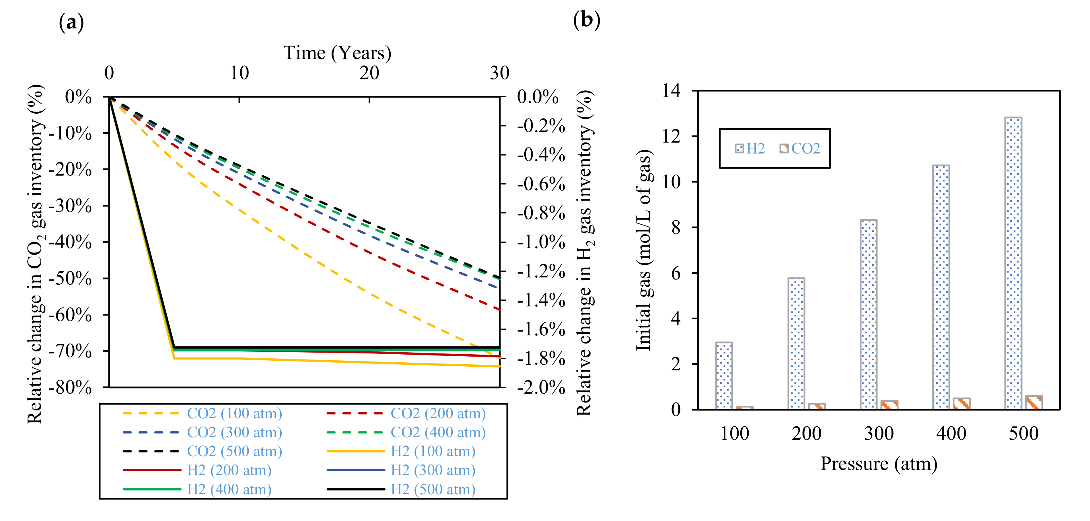
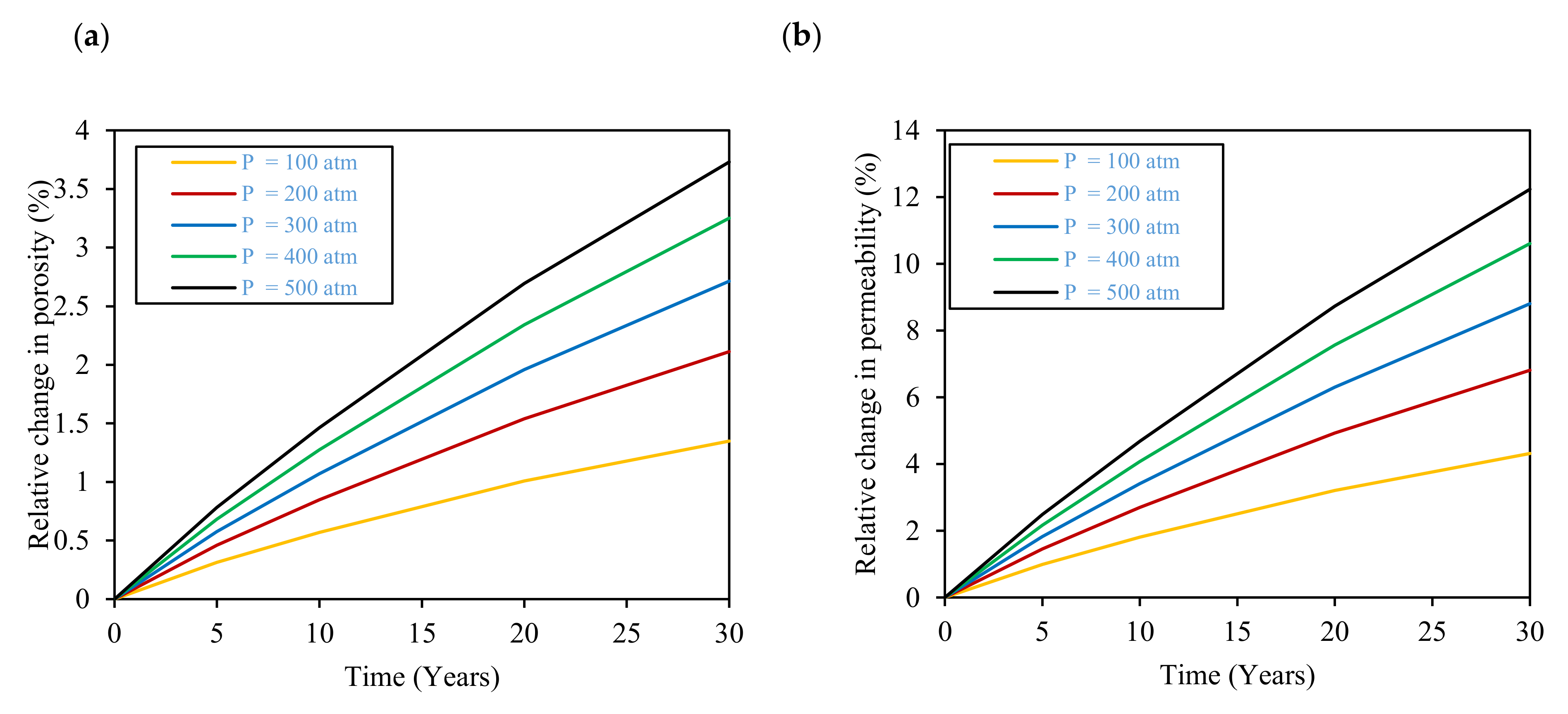
3.2. Effect of Pressure

The effect of pressure on H2 and CO2 inventory and rock properties over 30 years at pressures between 100 and 500 atm have been determined. H2 and CO2 gas inventory decrease with time due to geochemical reactions (see Figure 6a). It can also be seen that the percentage of H2 and CO2 gas loss decreases with the increase in pressure. However, the increase in pressure reflects a higher initial amount of gas inside the reservoir as depicted in Figure 6b; hence, in absolute moles units, the amount of gas lost increases with pressure. For example, after 30 years of storage, the amount of CO2 lost at 100 atm is 0.0945 mol/L of gas, which is less than that lost at 500 atm, which is 0.298 mol/L of gas. In the current targeted underground hydrogen storage application, the reservoir pressure is around 400–500 atm; hence, a high amount of CO2 gas is expected to be stored inside the reservoir rock. H2 loss inside the reservoir is less than 2% over 30 years, which is negligible compared to CO2 gas loss, which can be up to 72% over the same period. This observation indicates that the H2 loss due to geochemical reactions is not expected to be pronounced; however, the CO2 loss is expected to be more pronounced, especially on the H2 withdrawal process. Because CO2 is intended to play the role of a cushion gas and maintain reservoir pressure to stabilise the H2 withdrawal processes [47]. Based on this remark, more CO2 gas can be injected as a cushion gas over the years to help maintain the cushion gas requirements.
The effect of pressure on reservoir rock porosity and permeability is also evaluated and results are shown in Figure 7. The increase in pressure increases the reservoir mineral dissolution, specifically, K-feldspar and calcite, and consequently increases the porosity of the reservoir. These results agree with the experimental observations of [48], where the increased pressure boosted the mineral dissolution process. The porosity of the reservoir (Figure 7a) increases by 3.7% over the term of 30 years at 500 atm due to mineral dissolution reactions. This indicates that a higher amount of gas can be stored inside the reservoir after the initial 30-year period. The increase in porosity consequently causes an increase in the reservoir’s permeability (Figure 7b). At 500 atm, the permeability can be increased by up to 12.3% relative to the initial permeability. This would enhance the fluid flow in the reservoir rock for both the injection and withdrawal processes; however, an important aspect is the effect of this change in reservoir minerals on the geomechanics of the reservoir rock and cap rock integrity. This aspect will be further investigated in the project in the next steps.

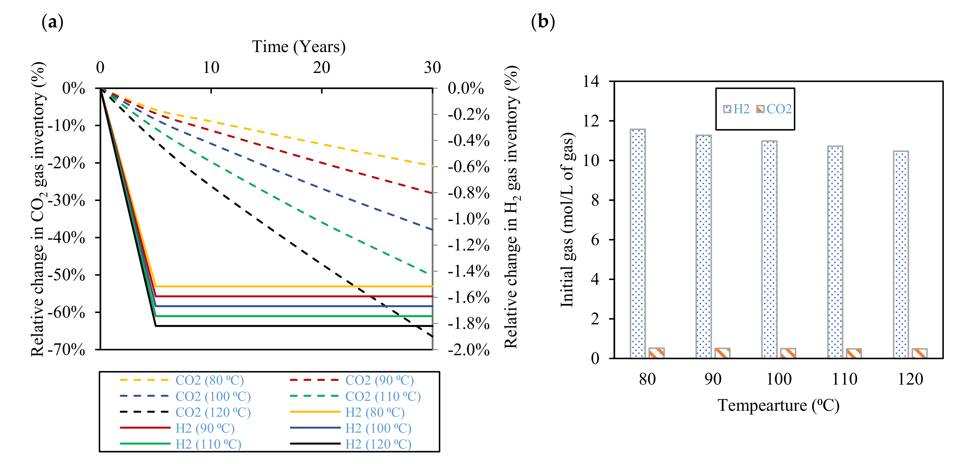
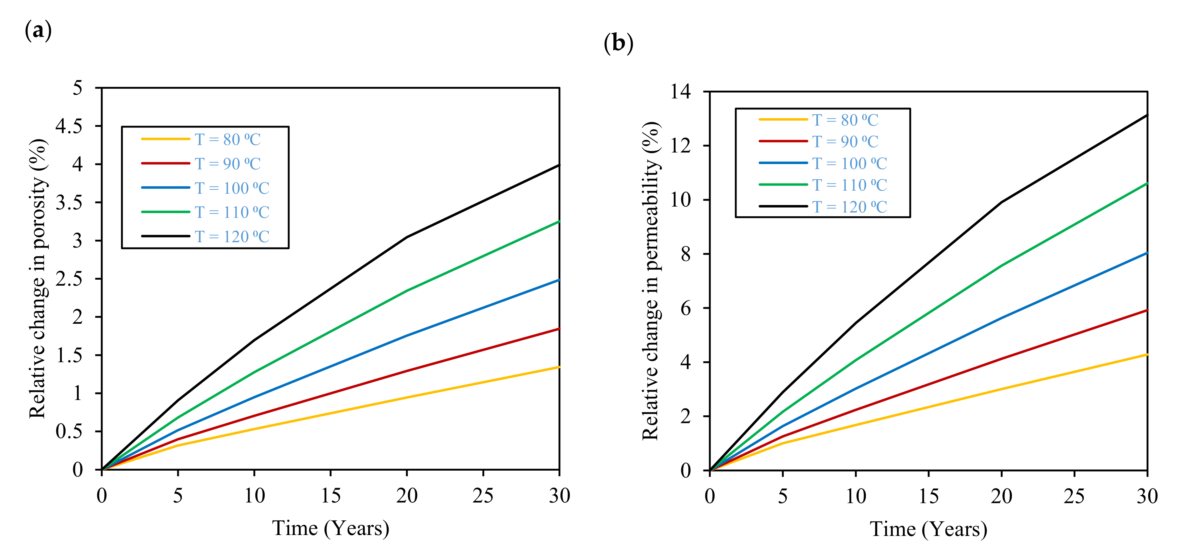
3.3. Effect of Temperature

Temperature affects both the gas solubility in water and the geochemical reactions’ equilibrium constants. The increase in temperature increases the percentage of initial gases lost from geochemical reactions as depicted in Figure 8a. The increase in temperature from 80 °C to 120 °C resulted in the CO2 losses inside the reservoir increasing from 20.8% to 67% over 30 years. The H2 losses were less than 2% over the same period. It is also important to make the distinction that the change in CO2 loss due to geochemical reactions in water in the presence of reservoir rock minerals is different to that in the absence of reservoir rock minerals, i.e., brine. CO2 loss in water in the presence of reservoir rock minerals increases with temperature opposite to that in the absence of reservoir rock minerals as shown in Figure 5. Hydrogen kinetic loss due to the increase in temperature is not as pronounced compared to the CO2 loss where the maximum hydrogen loss was less than 2% at 120 °C.
The effect of temperature on the rock properties, porosity, and permeability, was also investigated, and the results are shown in Figure 9. These modelling results agree with the experimental results of [48], where the temperature rise enhanced the mineral dissolution. Figure 9a shows that at 120 °C, porosity can rise by up to 4% of the original porosity over 30 years, and Figure 9b indicates that permeability can increase by up to 13% over the same period. This consequently results in an enhancement in gas storage capacity and reservoir flow properties. Hence, the temperature effects need to be taken into effect when planning underground hydrogen storage operations in the Etive formation of the targeted depleted oil reservoir.

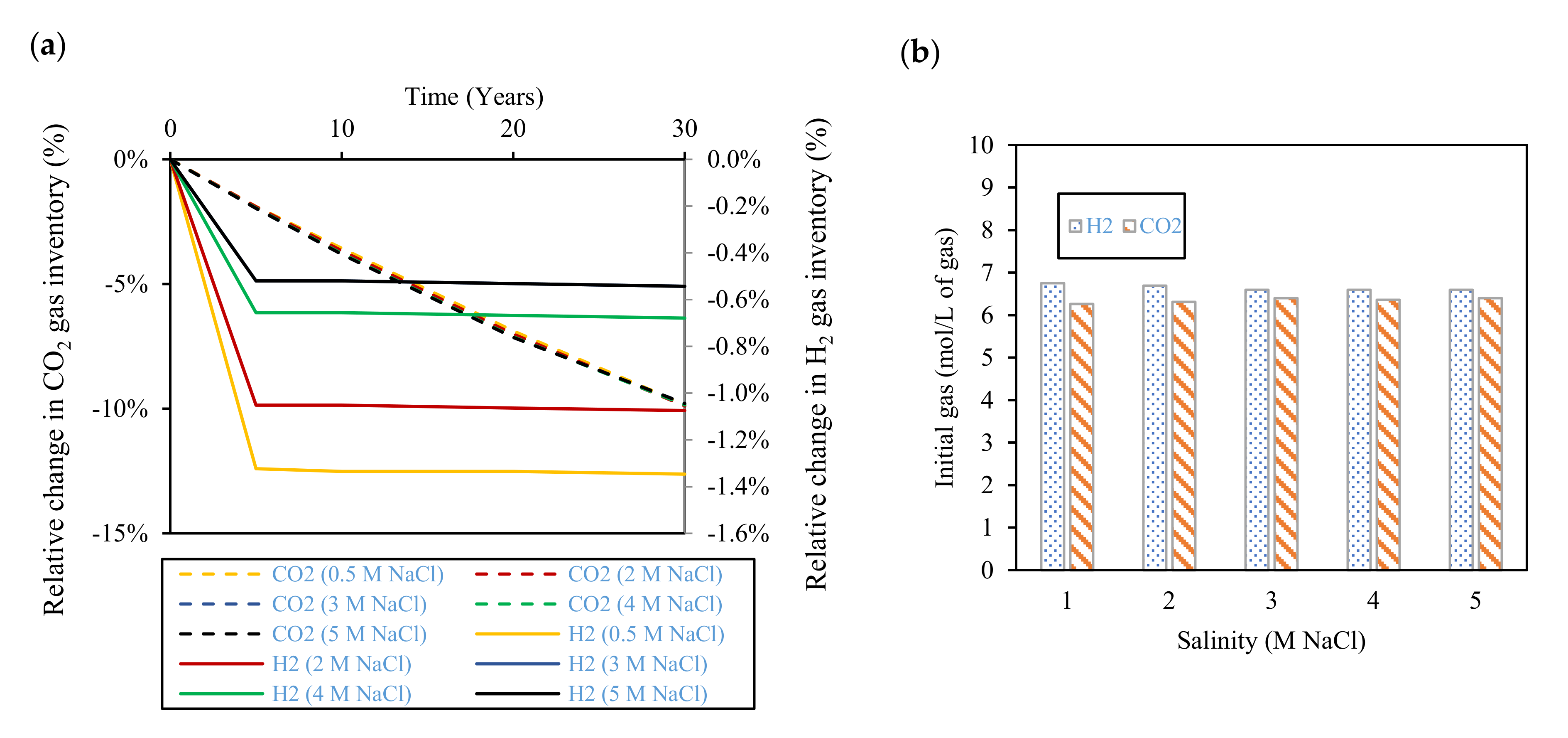
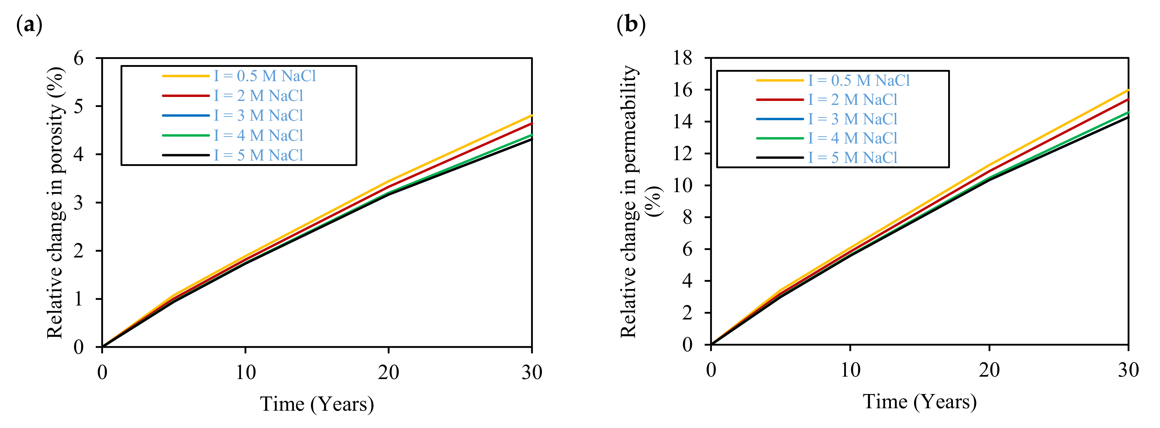
3.4. Effect of Salinity

Salinity affects the geochemical reactions occurring inside the reservoir. The increase in salinity decreases the amounts of gases lost due to geochemical activity inside the reservoir, as demonstrated in Figure 10. The effect of salinity on the gas inventory overall is not very pronounced as increasing the salinity from 0.5 to 5 M NaCl causes the relative loss of H2 to decrease from 1.3% to 0.5% over the 30 years. However, the salinity effect would be more pronounced in the case that the reservoir temperature was lower, which would then enhance the activity of the bacteria responsible for methanisation and sulphate reduction reactions, especially at lower salinities.
Salinity also has a minimal effect on reservoir porosity and permeability. Changing reservoir salinity in the model from 0.5 to 5 M NaCl, leads to the relative change in porosity in 30 years to decrease from 4.8% to 4.3% as shown in Figure 11a. Similarly, it can be seen from Figure 11b that salinity changes have a negligible effect on permeability. The overall reduction of porosity and permeability with salinity suggests a reduced dissolution of the reservoir minerals. Stillings and Brantley [49] found that increasing the salinity reduced the dissolution of feldspar at 25 °C and pH = 3.0. This can partially be attributed to the reduced CO2 dissolved in brine at higher salinities, which consequently limits the mineral dissolution process.

4. Conclusions

In this work, we investigated the effects of geochemical activities on the performance of underground hydrogen storage in the Etive sandstone formation in a depleted oil reservoir in the North Sea. The geochemical modelling was carried out using the geochemical code PhreeqC. The effects of varying pressure, temperature, and salinity on the injected gas inventory and the reservoir rock properties, porosity, and permeability, were evaluated over a period of 30 years. Results obtained from the geochemical investigations revealed the following:
-
The increase in reservoir pressure from 100 atm to 500 atm results in an increase in the dissolved hydrogen and carbon dioxide. Moreover, as a result of mineral dissolution reactions, the higher pressures result in an increase in the reservoir rock’s porosity and permeability. These porosity and permeability increases suggest that the reservoir’s storage capacity and ease of storage and withdrawal will be improved with time during storage. Nonetheless, due to the expected pressure changes during the injection and production stage of underground hydrogen storage, it would be important to understand the effects of pressure combined with the expected geochemical and geomechanical impacts on the reservoir rock’s strength during the underground hydrogen storage process.
-
Temperature increase enhances hydrogen gas and carbon dioxide gas dissolution and, consequently, gas losses, where losses of 2% and 67% in the stored hydrogen and carbon dioxide gases are expected at 120 °C after 30 years of storage, respectively. Moreover, higher temperatures and salinities limit microbial activity inside the reservoir and restrain the rate of biotic reactions that consume stored hydrogen. Therefore, the evaluation of the temperature and salinity effects on any UHS application should consider both biotic and abiotic reactions. However, there is a lack of experimental data on biotic reactions that must be properly addressed in future research.
-
In addition to the changes in porosity and permeability, this study shows that the losses of carbon dioxide gas inside the reservoir during underground hydrogen storage as a result of aqueous and mineral reactions are significant and may require remedial carbon dioxide gas to be injected to maintain cushion gas requirements.

Author Contributions

Conceptualization, M.S. and P.J.; methodology, M.S., P.J. and S.B.; software, M.S.; validation, M.S. and P.J.; formal analysis, M.S.; investigation, M.S.; resources, P.J.; writing—original draft preparation, M.S.; writing—review and editing, P.J.; visualization, M.S.; supervision, P.J. and S.B.; project administration, P.J.; funding acquisition, P.J. All authors have read and agreed to the published version of the manuscript.

Funding

This study was funded by the Net Zero Technology Centre, UK under the Hydrogen Innovation Grant scheme.

Data Availability Statement

Data used in this work can be shared privately upon request.

Conflicts of Interest

The authors declare no conflict of interest.

References

  1. Carden, P.O.; Paterson, L. Physical, chemical and energy aspects of underground hydrogen storage. Int. J. Hydrogen Energy 1979, 4, 559–569. [Google Scholar] [CrossRef]
  2. Gallo, A.B.; Simões-Moreira, J.R.; Costa, H.K.M.; Santos, M.M.; Moutinho dos Santos, E. Energy storage in the energy transition context: A technology review. Renew. Sustain. Energy Rev. 2016, 65, 800–822. [Google Scholar] [CrossRef]
  3. Abe, J.O.; Popoola, A.P.I.; Ajenifuja, E.; Popoola, O.M. Hydrogen energy, economy and storage: Review and recommendation. Int. J. Hydrogen Energy 2019, 44, 15072–15086. [Google Scholar] [CrossRef]
  4. McCay, M.H.; Shafiee, S. Hydrogen: An energy carrier. In Future Energy: Improved, Sustainable and Clean Options for Our Planet; Elsevier: Amsterdam, The Netherlands, 2020; pp. 475–493. [Google Scholar] [CrossRef]
  5. Das, D.; Veziroǧlu, T.N. Hydrogen production by biological processes: A survey of literature. Int. J. Hydrogen Energy 2001, 26, 13–28. [Google Scholar] [CrossRef]
  6. Davison, J.; Arienti, S.; Cotone, P.; Mancuso, L. Co-production of hydrogen and electricity with CO2 capture. Int. J. Greenh. Gas Control 2010, 4, 125–130. [Google Scholar] [CrossRef]
  7. Holladay, J.D.; Hu, J.; King, D.L.; Wang, Y. An overview of hydrogen production technologies. Catal. Today 2009, 139, 244–260. [Google Scholar] [CrossRef]
  8. Flesch, S.; Pudlo, D.; Albrecht, D.; Jacob, A.; Enzmann, F. Hydrogen underground storage—Petrographic and petrophysical variations in reservoir sandstones from laboratory experiments under simulated reservoir conditions. Int. J. Hydrogen Energy 2018, 43, 20822–20835. [Google Scholar] [CrossRef]
  9. Tarkowski, R. Underground hydrogen storage: Characteristics and prospects. Renew. Sustain. Energy Rev. 2019, 105, 86–94. [Google Scholar] [CrossRef]
  10. Zivar, D.; Kumar, S.; Foroozesh, J. Underground hydrogen storage: A comprehensive review. Int. J. Hydrogen Energy 2021, 46, 23436–23462. [Google Scholar] [CrossRef]
  11. Tarkowski, R. Perspectives of using the geological subsurface for hydrogen storage in Poland. Int. J. Hydrogen Energy 2017, 42, 347–355. [Google Scholar] [CrossRef]
  12. Tarkowski, R.; Uliasz-Misiak, B.; Tarkowski, P. Storage of hydrogen, natural gas, and carbon dioxide—Geological and legal conditions. Int. J. Hydrogen Energy 2021, 46, 20010–20022. [Google Scholar] [CrossRef]
  13. Muhammed, N.S.; Haq, B.; Al Shehri, D.; Al-Ahmed, A.; Rahman, M.M.; Zaman, E. A review on underground hydrogen storage: Insight into geological sites, influencing factors and future outlook. Energy Rep. 2022, 8, 461–499. [Google Scholar] [CrossRef]
  14. Hematpur, H.; Abdollahi, R.; Rostami, S.; Haghighi, M.; Blunt, M.J. Review of underground hydrogen storage: Concepts and challenges. Adv. Geo-Energy Res. 2022, 7, 111–131. [Google Scholar] [CrossRef]
  15. Pan, B.; Yin, X.; Ju, Y.; Iglauer, S. Underground hydrogen storage: Influencing parameters and future outlook. Adv. Colloid Interface Sci. 2021, 294, 102473. [Google Scholar] [CrossRef]
  16. Raza, A.; Arif, M.; Glatz, G.; Mahmoud, M.; Al Kobaisi, M.; Alafnan, S.; Iglauer, S. A holistic overview of underground hydrogen storage: Influencing factors, current understanding, and outlook. Fuel 2022, 330, 125636. [Google Scholar] [CrossRef]
  17. Delshad, M.; Umurzakov, Y.; Sepehrnoori, K.; Eichhubl, P.; Batista Fernandes, B.R. Hydrogen Storage Assessment in Depleted Oil Reservoir and Saline Aquifer. Energies 2022, 15, 8132. [Google Scholar] [CrossRef]
  18. Green, D.W.; Willhite, G.P. Enhanced Oil Recovery. Henry, L. Doherty Memorial Fund of AIME, Society of Petroleum Engineers: Richardson, TX, USA, 1998; Volume 6. [Google Scholar]
  19. Jadhawar, P.; Yang, J.; Chapoy, A.; Tohidi, B. Subsurface Carbon Dioxide Sequestration and Storage in Methane Hydrate Reservoirs Combined with Clean Methane Energy Recovery. Energy Fuels 2021, 35, 1567–1579. [Google Scholar] [CrossRef]
  20. Oldenburg, C.; Stevens, S.; Benson, S. Carbon sequestration in natural gas reservoirs: Enhanced gas recovery and natural gas storage. In Proceedings of the Greenhouse Gas Control Technologies—6th International Conference, Kyoto, Japan, 1–4 October 2002; pp. 691–696. [Google Scholar] [CrossRef]
  21. Yekta, A.E.; Pichavant, M.; Audigane, P. Evaluation of geochemical reactivity of hydrogen in sandstone: Application to geological storage. Appl. Geochem. 2018, 95, 182–194. [Google Scholar] [CrossRef]
  22. Bo, Z.; Zeng, L.; Chen, Y.; Xie, Q. Geochemical reactions-induced hydrogen loss during underground hydrogen storage in sandstone reservoirs. Int. J. Hydrogen Energy 2021, 46, 19998–20009. [Google Scholar] [CrossRef]
  23. Hassannayebi, N.; Azizmohammadi, S.; De Lucia, M.; Ott, H. Underground hydrogen storage: Application of geochemical modelling in a case study in the Molasse Basin, Upper Austria. Environ. Earth Sci. 2019, 78, 177. [Google Scholar] [CrossRef]
  24. Hemme, C.; van Berk, W. Hydrogeochemical Modeling to Identify Potential Risks of Underground Hydrogen Storage in Depleted Gas Fields. Appl. Sci. 2018, 8, 2282. [Google Scholar] [CrossRef]
  25. Hagemann, B.; Rasoulzadeh, M.; Panfilov, M.; Ganzer, L.; Reitenbach, V. Hydrogenization of underground storage of natural gas: Impact of hydrogen on the hydrodynamic and bio-chemical behavior. Comput. Geosci. 2016, 20, 595–606. [Google Scholar] [CrossRef]
  26. Gregory, S.P.; Barnett, M.J.; Field, L.P.; Milodowski, A.E. Subsurface microbial hydrogen cycling: Natural occurrence and implications for industry. Microorganisms 2019, 7, 53. [Google Scholar] [CrossRef] [PubMed]
  27. Bernardez, L.A.; De Lima, L.R.P.A.; De Jesus, E.B.; Ramos, C.L.S.; Almeida, P.F. A kinetic study on bacterial sulfate reduction. Bioprocess Biosyst. Eng. 2013, 36, 1861–1869. [Google Scholar] [CrossRef] [PubMed]
  28. Machel, H.G. Bacterial and thermochemical sulfate reduction in diagenetic settings—Old and new insights. Sediment. Geol. 2001, 140, 143–175. [Google Scholar] [CrossRef]
  29. Jørgensen, B.B.; Isaksen, M.F.; Jannasch, H.W. Bacterial sulfate reduction above 100°C in deep-sea hydrothermal vent sediments. Science 1992, 258, 1756–1757. [Google Scholar] [CrossRef]
  30. Thaysen, E.M.; McMahon, S.; Strobel, G.J.; Butler, I.B.; Ngwenya, B.T.; Heinemann, N.; Wilkinson, M.; Hassanpouryouzband, A.; McDermott, C.I.; Edlmann, K. Estimating microbial growth and hydrogen consumption in hydrogen storage in porous media. Renew. Sustain. Energy Rev. 2021, 151, 111481. [Google Scholar] [CrossRef]
  31. Amid, A.; Mignard, D.; Wilkinson, M. Seasonal storage of hydrogen in a depleted natural gas reservoir. Int. J. Hydrogen Energy 2016, 41, 5549–5558. [Google Scholar] [CrossRef]
  32. Laban, M. Hydrogen Storage in Salt Caverns: Chemical Modelling and Analysis of Large-Scale Hydrogen Storage in Underground Salt Caverns. Master’s Thesis, Delft University of Technology, Delft, The Netherlands, 2020. [Google Scholar]
  33. Zeng, L.; Hosseini, M.; Keshavarz, A.; Iglauer, S.; Lu, Y.; Xie, Q. Hydrogen wettability in carbonate reservoirs: Implication for underground hydrogen storage from geochemical perspective. Int. J. Hydrogen Energy 2022, 47, 25357–25366. [Google Scholar] [CrossRef]
  34. Zeng, L.; Keshavarz, A.; Xie, Q.; Iglauer, S. Hydrogen storage in Majiagou carbonate reservoir in China: Geochemical modelling on carbonate dissolution and hydrogen loss. Int. J. Hydrogen Energy 2022, 47, 24861–24870. [Google Scholar] [CrossRef]
  35. Parkhurst, D.; Appelo, C. Description of Input and Examples for PHREEQC Version 3: A Computer Program for Speciation, Batch-Reaction, One-Dimensional Transport, and Inverse Geochemical Calculations; U.S. Geological Survey: Denver, CO, USA, 2013. [Google Scholar]
  36. Saeed, M.; Jadhawar, P.; Ayirala, S.C.; Abhishek, R.; Zhou, Y. Modelling the effects of reservoir parameters and rock mineralogy on wettability during low salinity waterflooding in sandstone reservoirs. J. Pet. Sci. Eng. 2022, 215, 110676. [Google Scholar] [CrossRef]
  37. Saeed, M.; Jadhawar, P.; Zhou, Y.; Abhishek, R. Triple-layer surface complexation modelling: Characterization of oil-brine interfacial zeta potential under varying conditions of temperature, pH, oil properties and potential determining ions. Colloids Surf. A Physicochem. Eng. Asp. 2022, 633, 127903. [Google Scholar] [CrossRef]
  38. Tavassoli, S.; Korrani, A.K.N.; Pope, G.A.; Sepehrnoori, K. Low-salinity surfactant flooding—A multimechanistic enhanced-oil-recovery method. SPE J. 2016, 21, 744–760. [Google Scholar] [CrossRef]
  39. Saeed, M.; Jadhawar, P. Surface Complexation Modeling of HPAM Polymer–Brine–Sandstone Interfaces for Application in Low-Salinity Polymer Flooding. Energy Fuels 2023, 37, 6585–6600. [Google Scholar] [CrossRef]
  40. Jordan, M.; Sorbie, K.; Jiang, P.; Yuan, M.; Todd, A.; Taylor, K. Mineralogical Controls on Inhibitor Adsorption/Desorption in Brent Group Sandstone and Their Importance in Predicting and Extending Field Squeeze Lifetimes. In Proceedings of the European Production Operations Conference and Exhibition, Aberdeen, UK, 15–17 March 1994. [Google Scholar] [CrossRef]
  41. Chabab, S.; Théveneau, P.; Coquelet, C.; Corvisier, J.; Paricaud, P. Measurements and predictive models of high-pressure H2 solubility in brine (H2O+NaCl) for underground hydrogen storage application. Int. J. Hydrogen Energy 2020, 45, 32206–32220. [Google Scholar] [CrossRef]
  42. Alvarez, J.; Crovetto, R.; Fernandez-Prini, R. The Dissolution of N2 and of H2 in water from room temperature to 640 K. Ber. Bunsenges. Phys. Chem. 1988, 92, 935–940. [Google Scholar] [CrossRef]
  43. Wiebe, R.; Gaddy, V.L. The Solubility of Hydrogen in Water at 0, 50, 75 and 100° from 25 to 1000 Atmospheres. J. Am. Chem. Soc. 1934, 56, 76–79. [Google Scholar] [CrossRef]
  44. Tödheide, K.; Franck, E.U. Das zweiphasengebiet und die kritische kurve im system kohlendioxid-wasser bis zu drucken von 3500 bar. Z. Phys. Chem. 1963, 37, 387–401. [Google Scholar] [CrossRef]
  45. Ahmadi, P.; Chapoy, A. CO2 solubility in formation water under sequestration conditions. Fluid Phase Equilibria 2018, 463, 80–90. [Google Scholar] [CrossRef]
  46. Rumpf, B.; Nicolaisen, H.; Öcal, C.; Maurer, G. Solubility of carbon dioxide in aqueous solutions of sodium chloride: Experimental results and correlation. J. Solut. Chem. 1994, 23, 431–448. [Google Scholar] [CrossRef]
  47. Saeed, M.; Sayani, J.K.S.; Jadhawar, P. Evaluating the Performance of Various Cushion Gas Types for Underground Hydrogen Storage in an Aquifer. In Proceedings of the 1st International Conference on Green Hydrogen for Global Decarbonisation, Gandhinagar, India, 17–18 March 2023. [Google Scholar]
  48. Giammar, D.E.; Bruant, R.G.; Peters, C.A. Forsterite dissolution and magnesite precipitation at conditions relevant for deep saline aquifer storage and sequestration of carbon dioxide. Chem. Geol. 2005, 217, 257–276. [Google Scholar] [CrossRef]
  49. Stillings, L.L.; Brantley, S.L. Feldspar dissolution at 25°C and pH 3: Reaction stoichiometry and the effect of cations. Geochim. Cosmochim. Acta 1995, 59, 1483–1496. [Google Scholar] [CrossRef]
Figure 1. Comparison between modelling results and literature data [41] for H2 solubility in pure water.
Hydrogen 04 00023 g001
Figure 2. Comparison between modelling results and literature data [41] for H2 solubility in 1 M NaCl water.
Hydrogen 04 00023 g002
Figure 3. Comparison between modelling results and literature data [41] for H2 solubility in 5 M NaCl water.
Hydrogen 04 00023 g003
Figure 4. Comparison between modelling results and literature data [43,44] for CO2 solubility in pure water.
Hydrogen 04 00023 g004
Figure 5. Comparison between modelling results and literature data [46] for CO2 solubility in 4 M NaCl water.
Hydrogen 04 00023 g005
Figure 6. (a) Relative change in H2 and CO2 gas inventory over 30 years at various pressure values. (b) Initial H2 and CO2 gas present at various pressure values.
Hydrogen 04 00023 g006
Figure 7. Kinetic effect of pressure on (a) porosity and (b) permeability over a 30-year period.
Hydrogen 04 00023 g007
Figure 8. (a) Relative change in H2 and CO2 gas inventory over 30 years at various temperature values. (b) Initial H2 and CO2 gas present at various temperature values.
Hydrogen 04 00023 g008
Figure 9. Kinetic effect of temperature on (a) porosity and (b) permeability over a 30-year period.
Hydrogen 04 00023 g009
Figure 10. (a) Relative change in H2 and CO2 gas inventory over 30 years at various salinity values. (b) Initial H2 and CO2 gas present at various salinity values.
Hydrogen 04 00023 g010
Figure 11. Kinetic effect of salinity on (a) porosity and (b) permeability over a 30-year period.
Hydrogen 04 00023 g011
Table 1. Adopted mineral geochemical reactions in the model [24].
Mineral Phases ReactionLog K @ 25 °C
KAlSi 3 O 8 + 8 H 2 O   =   K + +   Al OH 4 + 3 H 4 SiO 4 −20.573
NaAlSi 3 O 8 + 8 H 2 O   =   Na + +   Al OH 4 + 3 H 4 SiO 4 −18
Al 2 Si 2 O 5 OH 4 + 6 H + =   H 2 O   + 2 H 4 SiO 4 + 2 Al 3 + 7.435
SiO 2 + 2 H 2 O   = H 4 SiO 4 3.95
CaCO 3 =   CO 3 2 +   Ca 2 + 8.48
FeS 2 + 2 H + + 2 e =   Fe 2 + + 2 HS −18.479
K 0.6 Mg 0.25 Al 2.3 Si 3.5 O 10 OH 2 + 11.2 H 2 O   = 0.6 K + + 0.25 Mg 2 + + 2.3 Al OH 4 + 3.5 H 4 SiO 4 + 1.2   H + −40.267
CaMg CO 3 2 =   Ca 2 + +   Mg 2 + + 2 CO 3 2 −17.09
Table 2. Reservoir rock mineralogy [40].
MineralWeight%
Quartz78
Feldspar11
Muscovite2
Carbonate1
Pyrite2
Kaolinite + Illite5
Table 3. Formation water chemistry.
IonConcentration (mg/l)
Sr2+46
Ba2+67
Cl14,740
SO42-18
Mg2+62
Ca2+290
K+190
Na+9210
Fe3+<0.10
Table 4. Range of parameters in geochemical investigations.
ParameterBase CaseMinimumMaximum
Pressure (atm)400100500
Temperature (°C)10080120
Salinity (M NaCl)0.50.55
Disclaimer/Publisher’s Note: The statements, opinions and data contained in all publications are solely those of the individual author(s) and contributor(s) and not of MDPI and/or the editor(s). MDPI and/or the editor(s) disclaim responsibility for any injury to people or property resulting from any ideas, methods, instructions or products referred to in the content.

