Article

Influence of Physical and Mechanical Parameters on Cavitation Erosion and Antifouling Behaviour of Multilayer Silica-Based Hybrid Sol–Gel Coatings on Aluminium Alloys

1
Department of Aerospace and Mechanical Engineering, South East Technological University, R93 V960 Carlow, Ireland
2
The Center for Research and Enterprise in Engineering (engCORE), South East Technological University, R93 V960 Carlow, Ireland
3
Department of Applied Sciences, South East Technological University, R93 V960 Carlow, Ireland
4
Centre for Research in Engineering and Surface Technology (CREST), FOCAS Institute, Technological University Dublin, City Campus, Kevin Street, D08 CKP1 Dublin, Ireland
*
Author to whom correspondence should be addressed.
Eng 2023, 4(2), 1393-1408; https://doi.org/10.3390/eng4020081
Submission received: 27 March 2023 / Revised: 7 May 2023 / Accepted: 11 May 2023 / Published: 15 May 2023
(This article belongs to the Section Materials Engineering)

Abstract

:
Sol–gel coatings can provide anti-fouling and erosion resistance while being safe to use in the marine environment. MAPTMS/ZPO multilayer coatings deposited on the AA2024-T3 aluminium surface using the dip-coating method at three different thicknesses (2, 4, and 6 µm) are investigated in this work. The coatings are characterised in terms of physical and mechanical properties, and these properties are investigated in comparison to previously obtained cavitation erosion resistance levels of the coatings. Additionally, the efficiency of the coatings against biofouling was assessed using Phaeodactylum tricornutum, a marine diatom. The influence of the formation of organic–inorganic hybrid materials (OIHMs) from the prepared sols on the physical and mechanical properties of the coatings were analysed. A variety of techniques, including attenuated total reflection Fourier-transform infrared spectroscopy (ATR-FTIR), water contact angle (WCA) measurements, pencil hardness testing, cross-cut adhesion testing, a roughness profilometer, and nano-indentation, were performed on the bare and coated substrates. The results indicated that the thickness, hydrophobicity, and adherence of the coatings are strongly affected by the roughness. The elastic strain failure (H/E) and resistance to plastic deformation (H3/E2) coefficients were higher than those of the bare substrate before and after the cavitation erosion test, indicating that the coating had a higher ability to withstand deformation in comparison to the substrate alone. Furthermore, the microscopic analysis of a marine diatom, Phaeodactylum tricornutum, revealed that coated surfaces exhibited a decreased rate of bacterial adhesion and biofilm formation. The data show that sol–gel formed coatings outperform uncoated AA2024-T3 in terms of hardness, elastic strain, plastic deformation, and biofouling resistance. These characteristics are attributed to the coatings’ mechanical and adhesive capabilities, as well as their tribological behaviour.

1. Introduction

Marine resources are critical to global economic growth. Presently, there are financial imperatives for securing marine transport infrastructure [1]. One of the most frequent challenges for marine equipment degradation is cavitation erosion [2]. Cavitation erosion is caused by the repetitive effects of shock waves and microjets generated by bubble collapse in a liquid [3,4,5]. Coatings with erosion resistance capacity are commonly applied on the surface of flow passage components to improve their resistance to cavitation erosion. Additional challenges to maritime devices include biofouling. Biofouling occurs when marine organisms such as proteins, bacteria, algae, molluscs, and barnacles precipitate onto any surface exposed to seawater. Such biofouling can increase corrosion, reduce manoeuvrability, and adversely affect fuel consumption [6,7]. The yearly economic cost of biocorrosion is projected to be over USD 500 billion [8]. Many approaches to addressing the issue of marine fouling have been presented [9,10,11]. A traditional model to remove fouling organisms is mechanical decontamination; however, it is both costly and ineffective. Potential prevention techniques for avoiding marine biofouling are surface modification, incorporating chemical vapor deposition, traditional antifouling paints containing Tributyltin (TBT), the sol–gel approach, etc. [12,13,14]. Surface modification, however, calls for specialized processing that would be challenging to use on the scale of marine-based equipment and components. Additionally, the International Maritime Organisation’s Marine Environmental Protection Committee (MEPC) previously suggested a worldwide prohibition on the use of TBT in antifouling paints, which was to be implemented gradually over a decade starting from 1998 [14].
Chromate conversion coatings (CCCs) have been used for decades as a pre-treatment for various aluminium alloys, providing excellent adhesion and corrosion protection. Regardless, the active component in CCCs is hexavalent chromium, which is extremely carcinogenic and has been banned by the European Union under REACH regulations [15,16]. Additionally, toxic-metal-based antifoulants have historically been used to reduce fouling on ship hulls. Biocidal metals, including lead, arsenic, and mercury, and their organic derivatives have been banned, owing to the environmental concerns they presented [17].
Environmentally compliant coating alternatives on Al2O3 alloys have been investigated. Fahim et al. created a form of superhydrophobic cavitation-resistant coating and closely investigated its cavitation resistance mechanism [18]. To date, most research teams have encountered difficulties adequately combining antifouling and anti-cavitation functionalities within coatings [19]. Therefore, there is a strong need for the development of environmentally friendly coatings (an antifouling coating with erosion resistance) for the metallic substrates [20]. One of the promising replacements for the chromate conversion coatings on aluminium are sol–gel coatings [21]. The sol–gel process offers a low-temperature route to carefully control the introduction of an array of additives to polymer solutions. The choice of such additives can improve the physical and chemical properties of the coatings. Additionally, it is also possible to cure the coated substrate at relatively low temperatures [22,23]. The sol–gel process also allows the introduction of organic molecules into an inorganic network, thus forming organic–inorganic hybrid coatings [24,25]. These hybrid coating are of industrial interest as their properties can be changed constantly to form an ideal coating [26]. The inorganic components improve the adhesion, durability, and scratch resistance when coated on metallic substrates, whereas the organic components enhance the functional compatibility, flexibility, and density of the coatings [27]. Additionally, the incorporation of organofunctional silanes can strengthen the mechanical properties of the coating system [28,29]. Among various hybrid organic–inorganic coating materials synthesized via the sol–gel process, ORMOSIL coatings are appealing because of their ease of preparation, reactivity with a wide range of surfaces, low curing temperatures, extended chemical and physical durability, and convenience of application, which can contribute to high corrosion and antifouling protection properties [30,31]. The most commonly used sol–gel formulations for the preparation of hybrid coatings for corrosion protection are derived from the hydrolysis and condensation of semimetal alkoxides, which contain functional groups such as epoxy and methacrylic connected to the central atom by a stable Si-C bond. The formulations involved in the preparations of hybrid coatings to protect the metal substrate from damage are based on the methacrylic group in MAPTMS [32,33,34]. Furthermore, the chemical resistance of these hybrid coatings can be improved by adding more reactive, non-silane alkoxide precursors. Zirconium isopropoxide is a well-known precursor that influences the kinetics of hydrolysis and condensation reactions, forming some Si-O-Zr bonds and reducing the number of silanol groups, which is usually necessary for most of the applications [35,36]. One study on the application of OIH sol–gel coatings on aluminium alloys reported that the interfacial adhesion and barrier properties of the films are greatly dependent on the ratio of chemical constituents [37,38,39,40]. Additionally, the optical [41,42], electrical [43], and surface morphology [44] of the inorganic surfaces can be altered by combining network modifiers such as transition metal (TM) alkoxides or ionic liquids in silicate-based materials. Physicochemical properties such as morphology and mechanical and surface features that rely on the interactions between TM and silicate precursors are exhibited by the sol–gels prepared from such materials. In addition, the physicochemical properties depend on various factors such as the preparation conditions, pH, rate of hydrolysis, and stabilisation temperature [32].
Surface roughness and hardness play an important role in tribology as they have a significant impact on the performance and service life of engineering components. The wear and corrosion behaviour of WC-Co coatings that were sprayed, ground, and nanofinished were examined and compared [45]. The authors reported that slower corrosion is caused by a reduced interfacial area caused by nanoscale surface roughness and the existence of protective oxide coatings. The tribological performance of Al-SiC composite was investigated by Wang and Rack, who reported that the surface roughness had an effect on initial wear rates [46]. Bayer and Sirico [47] reported that the wear resistance of various materials depended on surface roughness. The corrosion behaviour of various metallic components are also affected by surface roughness [48]. Studies on the pitting susceptibility and corrosion behaviour of stainless steel, titanium alloys, copper, and magnesium alloys have reported that increasing the surface roughness increases the pitting and corrosion behaviour [48,49,50,51]. Previous research has examined the impact of substrate roughness on various properties of sol–gel coatings applied on metallic substrates [52,53,54]. The influence of surface roughness, hardness, and the elastic modulus on the cavitation erosion resistance (CER) of sol–gel coatings prepared from MAPTMS-ZPO on AA2024-T3 has not been addressed. Additionally, the biofouling activity of the marine diatom Phaeodactylum tricornutum on AA2024-T3 has not been reported previously. Among the diatoms, P. tricornutum is one of the most widely used model organisms in many research fields, including marine ecotoxicology [55]. It is also known to be sensitive to changes in environmental conditions, making it an effective indicator of how well coatings protect against environmental stressors such as UV radiation, fouling, and corrosion [56].
In previous work [57], the authors reported the wear, corrosion, and cavitation erosion behaviour of the multilayer sol–gels prepared from 3-trimethoxysilylpropylmethacrylate (MAPTMS) and a zirconium complex of zirconium n propoxide (ZPO) and methacrylic acid (MAAH) with an addition of cross-linker HMDI (1 and 1.5%). Therefore, the aims of this study were to investigate the antifouling properties of the developed sol–gel coatings and analyse the effects of coating thickness on properties linked to cavitation erosion resistance.

2. Materials and Methods

2.1. Substrate Preparation

The substrate for the sol–gel coatings was AA2024-T3. Prior to the application of sol–gel, the AA2024-T3 panels were degreased using isopropanol and pre-treated using UniClean® 100 series, followed by drying using compressed air.

2.2. Sol–Gel Synthesis

The MAPTMS/ZPO/MAAH coating was prepared by combining a Si-based solution with nitric acid and a Zr-based solution with MAAH separately. The solutions were mixed with constant agitation for 45 min, and 1.5% HMDI was added to the coatings. The solution was then allowed to hydrolyse for 24 h. All reagents were obtained from Sigma Aldrich (Wicklow, Ireland). The coatings were applied to the substrates using a dip-coater at a withdrawal rate of 100 mm/min and cured in a hot-air oven at 120 °C for one hour to ensure a uniform coating. The coatings were applied once (SD), twice (DD), or three times (TD) and were denoted accordingly (Table 1).

3. Characterisation

3.1. Thickness Measurements

The dry film thickness was measured using an Elcometer 456 (Elcometer, Warren, MI, USA) Digital Coating Thickness Gauge.

3.2. Water Contact Angle

The wettability of the films was determined by measuring the contact angle using an FTA surface energy analyser (Newark, CA, USA) of a 10 µL water droplet placed on the film surface with a contact angle meter coupled with a CCD camera at room temperature.

3.3. Scratch Resistance

The scratch resistance of the coating was evaluated using a pencil hardness tester, following the ISO 15184:2012 standard [58]. The test involved using pencil leads of varying hardness categories (ranging from 6B to 6H) as scratch tools. The coated surface was brought into contact with the pencil, which was positioned at a 45° angle in a weighted carriage (Elcometer, USA) and then moved horizontally across the surface to create scratches.

3.4. Cross-Cut Adhesion

The adhesion between the coating layer and the substrate was assessed using the cross-cut tape test according to standard ASTM D 3359-09 [59]. A cross-cut pattern was cut into the coating, and adhesive tape was laid across the coated surface and then was slowly pulled away.

3.5. Surface Roughness Measurements

The surface roughness of the uncoated and coated substrates was evaluated using a surface roughness profile measurement device (SURFCOM 130A, Tokyo Seimitsu Co., Ltd., Tokyo, Japan) before and after the cavitation erosion test [53]. The evaluation length was 4 mm with a 0.25 cut-off, and three measurements were taken for each sample. The fundamental roughness parameter, Ra, was calculated as the arithmetical mean of the absolute values of the roughness profile departures from the mean line. The impact of roughness on adhesion was also investigated.

3.6. Nanoindentation Measurements

The hardness and the elastic modulus were measured using a NANOVEA CB500 (Nanovea, Irvine, CA, USA). The nanomechanical indentation testing was performed using a Berkovich diamond indenter with a maximum applied load of 50 mN. A loading and unloading force of 100 mN/min was applied, with a 10 s delay after unloading. The average of five nanoindentation curves was used to determine the hardness and modulus of the uncoated and sol–gel coated substrates. Elastic strain and resistance to plastic deformation H3/E2 were measured on the surface of samples.

3.7. Antifouling Activity

The antifouling activity of a microalgae, Phaeodactylum tricornutum, was tested using Algaltoxkit M (Microbiotests, Ghent, Belgium).

3.8. Preparation of Algal Culturing Medium

3.8.1. Preparation of Synthetic Sea Water

An amount of 1500 mL of deionized water was added to a 2-litre volumetric flask. The NaCl was mixed into the deionized water until the salt was completely dissolved. The volumetric flask was then filled with salts from the kit, including KCl, CaCl2·2H2O, MgCl2·6H2O, MgSO4·7H2O, NaHCO3, and H3BO3 in Table 2.

3.8.2. Preculturing of the Algae

Before pouring the microalgae (Phaeodactylum tricornutum) inoculum into a pre-culturing cell, the contents of the tube containing it were vigorously shaken. Before transferring the contents of the tube into the pre-culturing cell, the tube was rinsed twice with 7.5 mL of algal culturing media to ensure the complete transfer of the microalgae inoculum. The pre-culturing cell was covered with a lid and incubated in an incubator for three days at 20 °C (+/−2 °C) with constant uniform lighting provided by cool white fluorescent lights.

3.8.3. Preparation of Concentrated Algal Inoculum

After three days of incubation, the pre-culturing cell was shaken until the algal solution was homogenous. The calibration cell included in the kit was filled with 25 mL of algal culture media before being covered with the lid. This cell was placed in the spectrophotometer to calibrate it. The pre-culturing cell was placed in the spectrophotometer, and the optical density (OD1) was measured after 10 s. The number of algae (N1) that correlates with OD1 was determined using the optical density/algal number (OD/N) sheet included in the kit. Using the N1/N2 ratio, the dilution factor required to achieve an optical density equal to OD2 and an algal density of 1.106 cells/mL with N2 were calculated. The algal suspension from the culturing cell was transferred to a 100 mL flask, and enough algal culturing media were added to make a suspension with 1.106 cells/mL. The flask was vigorously shaken to evenly distribute the algae. The pre-culturing cell was rinsed, filled with 25 mL of the 1.106 algae cells/mL solution, and carefully agitated, and the OD was read after 10 s. The OD/N graph was examined to confirm that the OD corresponded to the desired OD2 value (1.106 algal cells/mL).

3.9. Transfer of the Substrate to the Test Vials

Coated and uncoated AA2024-T3 were transferred to holding trays containing 25 mL of the 1.106 algae cells/mL solution. The holding tray was incubated in an incubator for three days with cool white fluorescent lights providing constant uniform lighting.

3.10. Scoring of the Results

The inhibition of algal growth relative to the control was determined after three days of incubation by measuring the Optical Density (OD) of the algal suspensions in the long cells with a UV-spectrophotometer (UV 1800, Shimadzu, Tokyo, Japan) every day for three days, i.e., after 24 h, 48 h, and 72 h of exposure to the coated and uncoated substrate. Furthermore, the fouling activity of the marine algae on bare and coated substrates was studied using a digital microscope after 90 days of substrate immersion in the algal solution (Keyence VHX-500F, Milton Keynes, UK).

3.11. Statistical Analysis of the Data

When applicable, the statistical analysis was conducted using one-way analysis of variance (ANOVA), followed by the Tukey–Kramer post hoc test. The significance level was p ≤ 0.05. The software used to carry out the analysis was SPSS Statistics (IBM SPSS Statistics 2015, New York, NY, USA).

4. Results and Discussions

This study compares and reports on the physical, mechanical, and tribological characteristics of multilayer sol–gel coatings. The previous investigation [57] focused on the corrosion, abrasion, and cavitation erosion of bare and multilayer SG1.5 sol–gel-coated substrates. Table 3 displays the cavitation erosion results of bare metal and SG1.5 coatings, which were obtained from our previous research. The graph was discussed in our earlier work [59].

4.1. Thickness Measurements

The coating thickness was determined by calculating the average of at least five independent measurements for each sample. The number of dipping cycles was adjusted to vary the coating thickness. As shown in Figure 1, the thickness of the single-coated sample was found to be 2 µm, while the thickness of the coatings deposited with two and three dips increased by 4 µm and 6 µm, respectively.

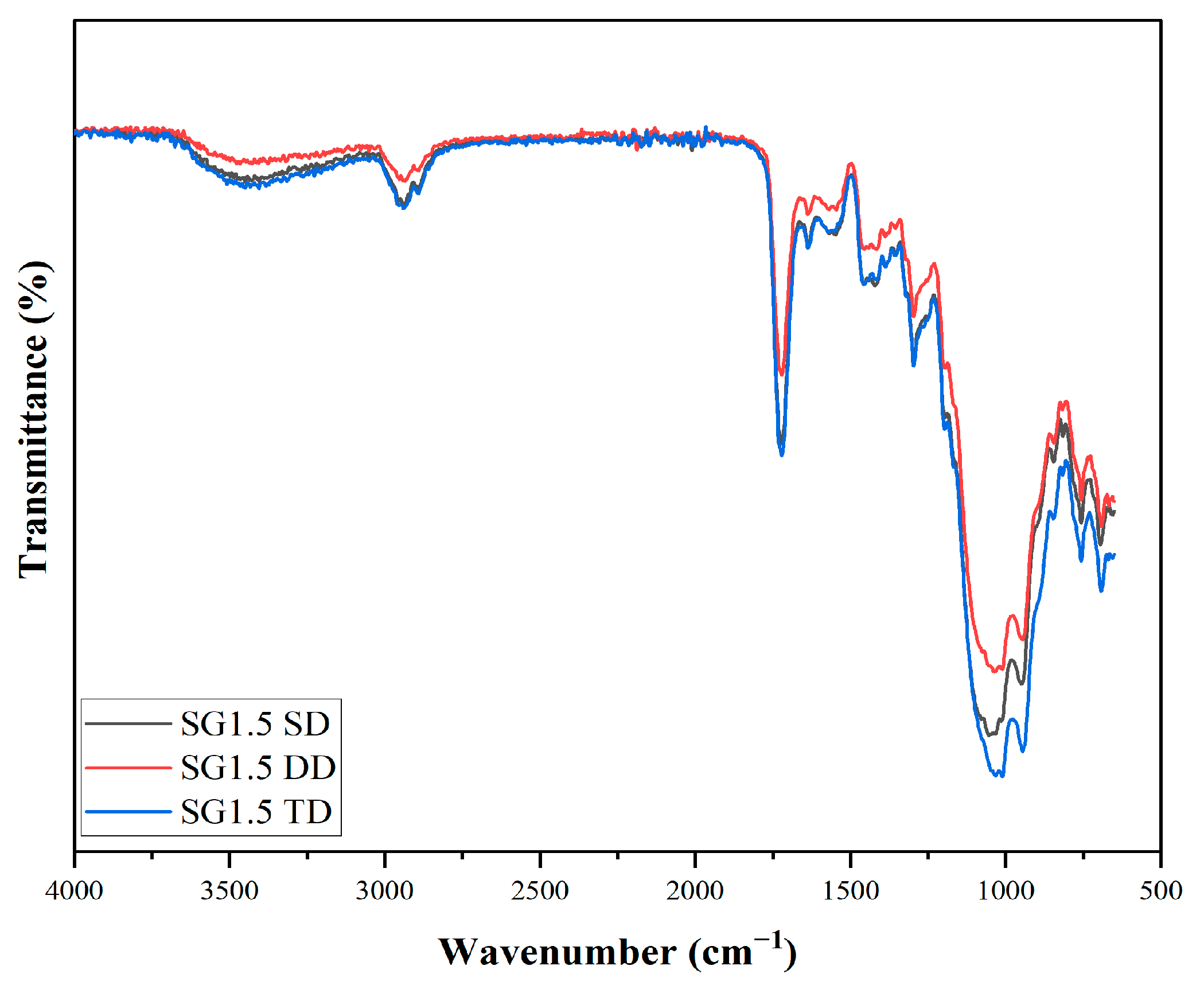
4.2. Attenuated Total Reflection-Fourier Transform Infrared Spectroscopy (ATR-FTIR)

The ATR-FTIR spectroscopy technique was utilized to analyse the chemical composition of sol–gel coatings applied to an aluminium substrate. The focus was on the development of the silicate network and the vibrational modes of various chemical species present in the coatings. The spectra of the coatings were collected in the ATR mode, covering a spectral range of 650–4000 cm−1. The hydrolysis process was indicated by the presence of Si-OH and Si-OCH3 bands at 3400 cm−1 and 2840 cm−1, respectively. The wide band in the 800–1200 cm−1 range indicated the formation of a silicate network resulting from the vibration strains of Si-OH, Si-O-Si, and Si-O-Zr in silanol. The band observed at 1170 cm−1 represented the Si-O-Si bond present in the methoxy-silane groups of MAPTMS. The Si-O-Si bond reflects the condensation process and the formation of a silicon dioxide network. The bands observed in the 1300–1650 cm−1 range corresponded to the Zr-OH and Zr-O-C bonds present in the zirconium complex (Figure 2).

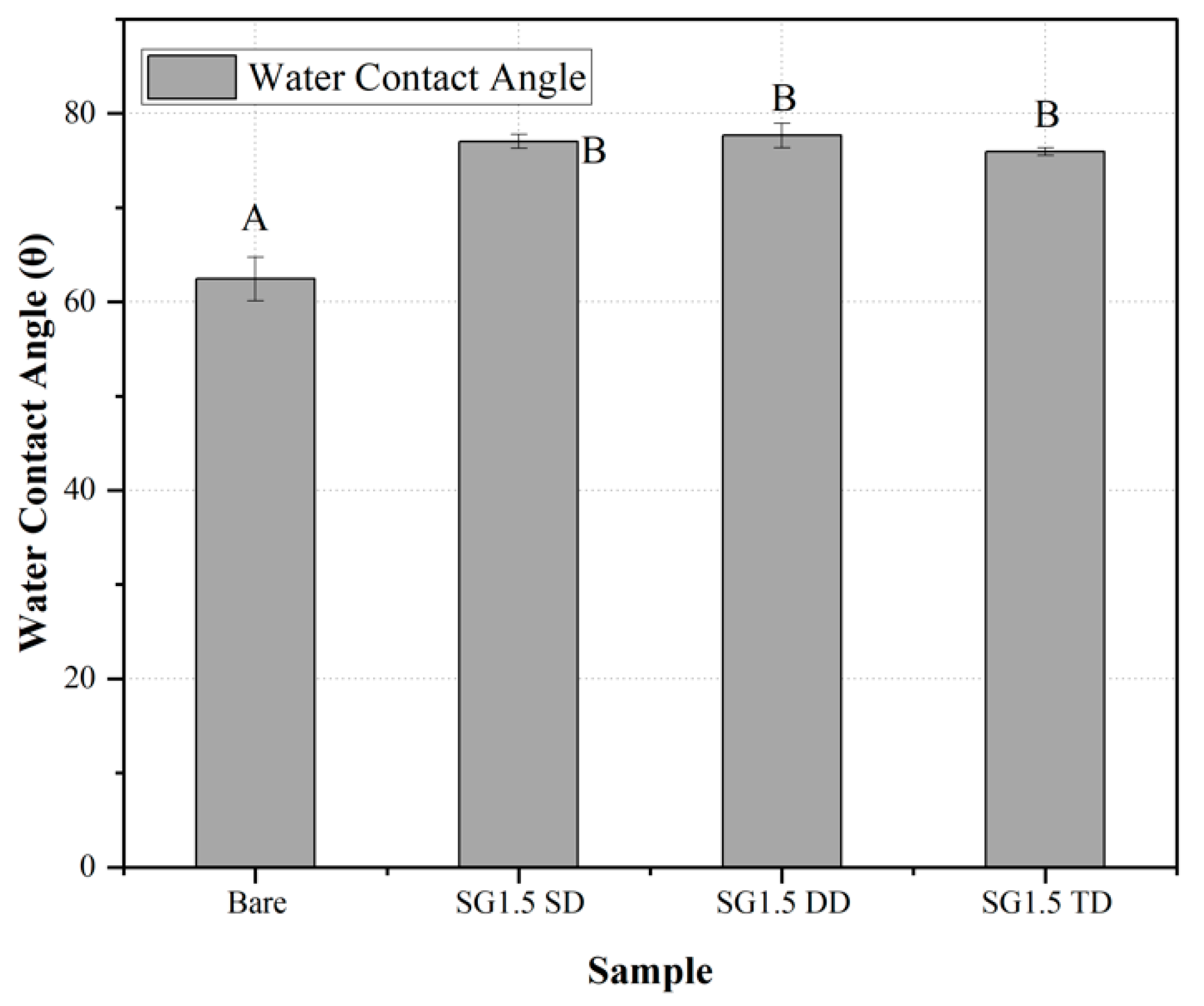
4.3. Contact Angle Measurements

Contact angles were measured at five distinct locations for each coated sample, and the average value was selected as the contact angle. The wetting behaviour of the hydrophobic surfaces is affected by their chemical composition and geometric microstructure. The hydrolytic stability of Si-C bonds causes the film’s surface to become hydrophobic, and the inclusion of methyl groups in MAPTMS improves water repellence. The contact angle of water on the surface is an indicator of the surface’s hydrophobicity. As expected, the thickness of the coatings increased as the withdrawal speed increased. Contact angles are a surface property, so they should be assumed to be roughly the same for all thicknesses and not vary much with thickness. There was no visible water residue on the film surface, and water droplets rolled off at all points on the film surface. The water contact angles of the single-, double-, and triple-coated samples were found to be in the range of 75–77° (Figure 3). However, compared to the single- and triple-coated samples, the water contact angle of the double-coated sample was higher but generally within one standard deviation of the other coatings.

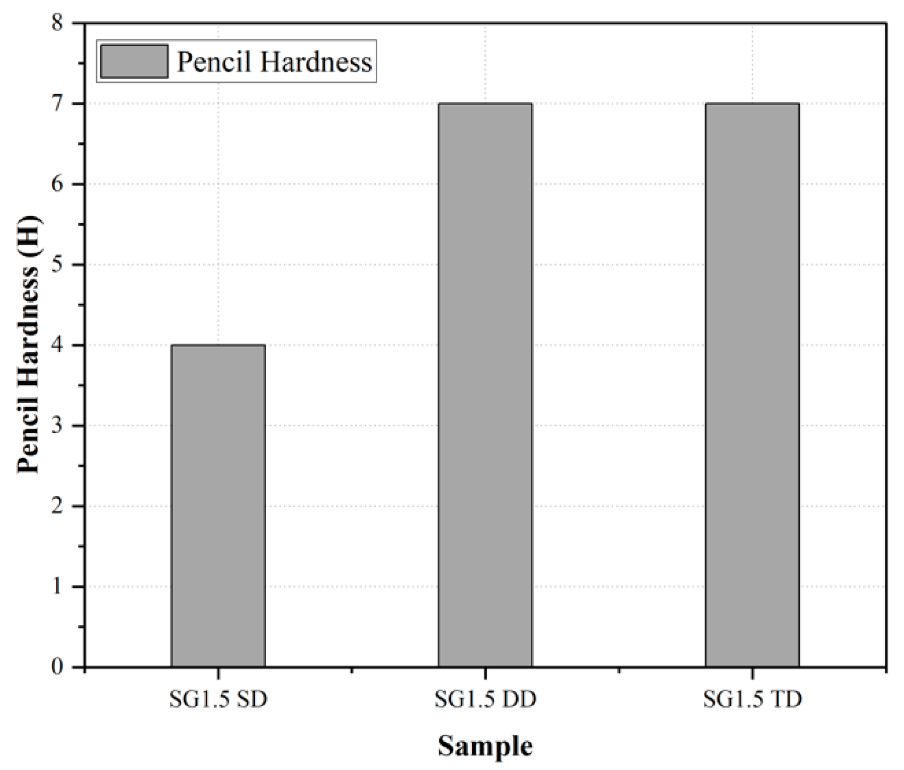
4.4. Pencil Hardness Test

The pencil hardness of the coating was evaluated using the degree of hardness of the pencil that did not leave a scratch on the coated surface, following the standard [58] ISO 15184:2012 standard. Based on the results presented in Figure 4, it can be concluded that the scratch resistance of the coatings increased with an increase in the number of layers and the thickness of the coating. Multi-layered coatings were found to have a smoother surface and stronger cross-linking between the inorganic and organic components, resulting in higher scratch resistance. Specifically, the single-coated sample achieved a pencil hardness of 4H, while the second and third layers of dip-coating showed a significant improvement, achieving a pencil hardness of 7H.

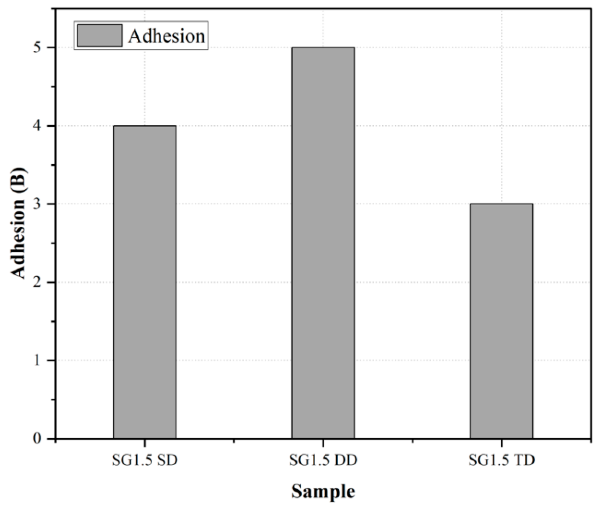
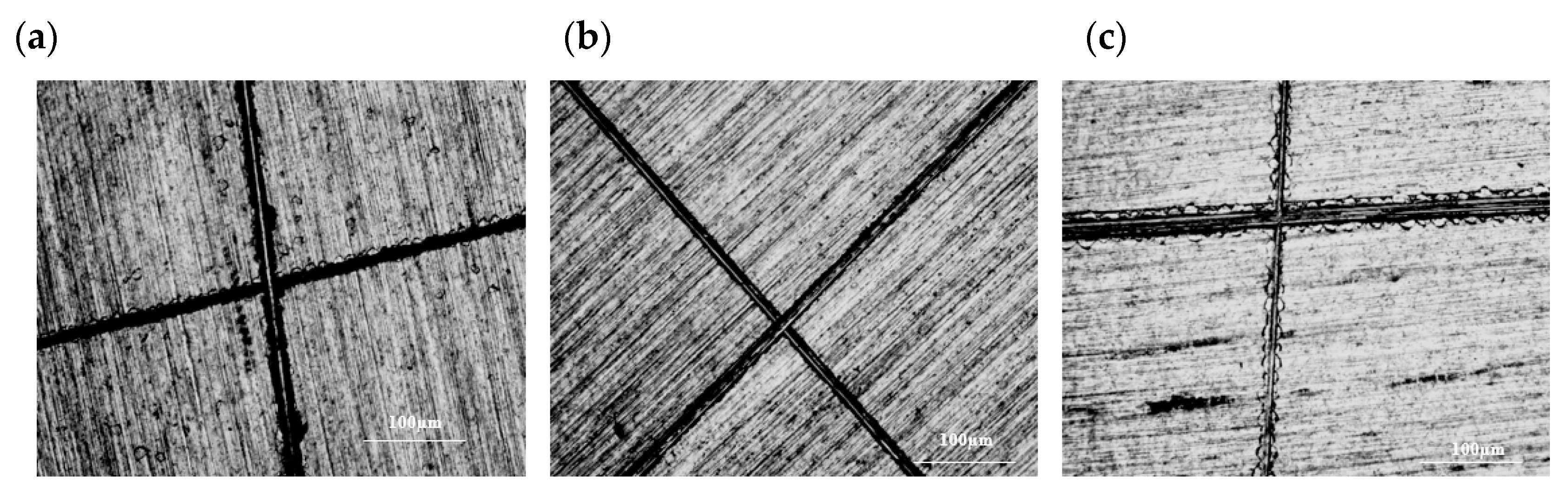
4.5. Cross-Cut Adhesion Test

To determine the degree of adhesion of the coating to the surface, a cross-cut adhesion test was conducted. The adhesion was rated on a scale of 0B to 5B, with 5B representing excellent adhesion and 0B indicating weak adhesion. According to the standard [59], SG1.5 SD received a grade of 3B, indicating that the coating had peeled off at the edges and intersections, but only 5% of the area was affected. SG1.5 TD received a rating of 4B, indicating that less than 5% of the area was affected. SG1.5 DD received a grade of 5B, indicating that the cut edges were smooth, and the coatings did not delaminate from the substrate. SG1.5 DD was found to have better adhesion to the substrate than the other samples, as shown in Figure 5. The resistance of the coating to its separation from the substrate was examined using a microscope in Figure 6.

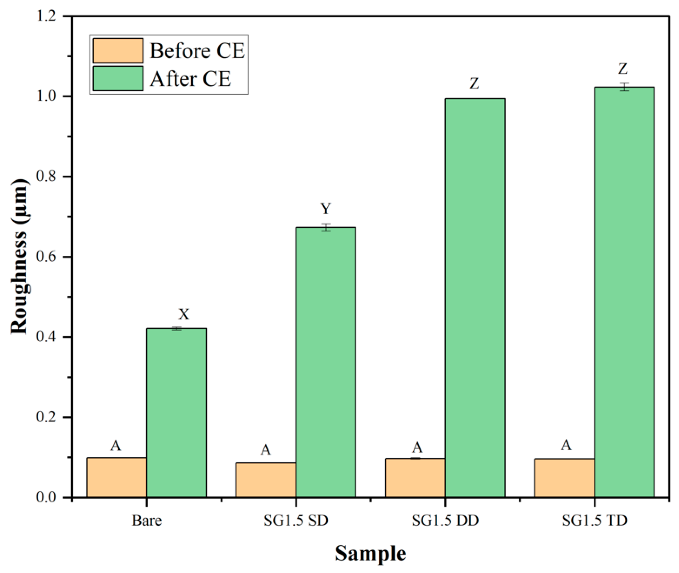
4.6. Surface Roughness Measurements

Surface observations show that the location of roughness measurements has a substantial impact on the acquired results and their interpretation. For this reason, the surface roughness was assessed for the coatings, which covers the whole degraded region (for cavitation eroded samples). The roughness values of the coated samples were found to be lower than those of the uncoated samples before the cavitation test. Following the cavitation process, the roughness values increased in both coated and bare samples (Figure 7). An increase in surface roughness after cavitation erosion is expected as the process can cause microcracks and material removal on the surface. The higher surface roughness of the SG1.5 TD sample after cavitation erosion is likely due to its thicker coating, which may have been able to absorb more of the energy from the cavitation bubbles; thus, it experienced more material loss and surface damage. The correlation between surface roughness and mass/volume loss further supports the idea that surface roughness is an important factor in the erosion resistance of coatings [59].

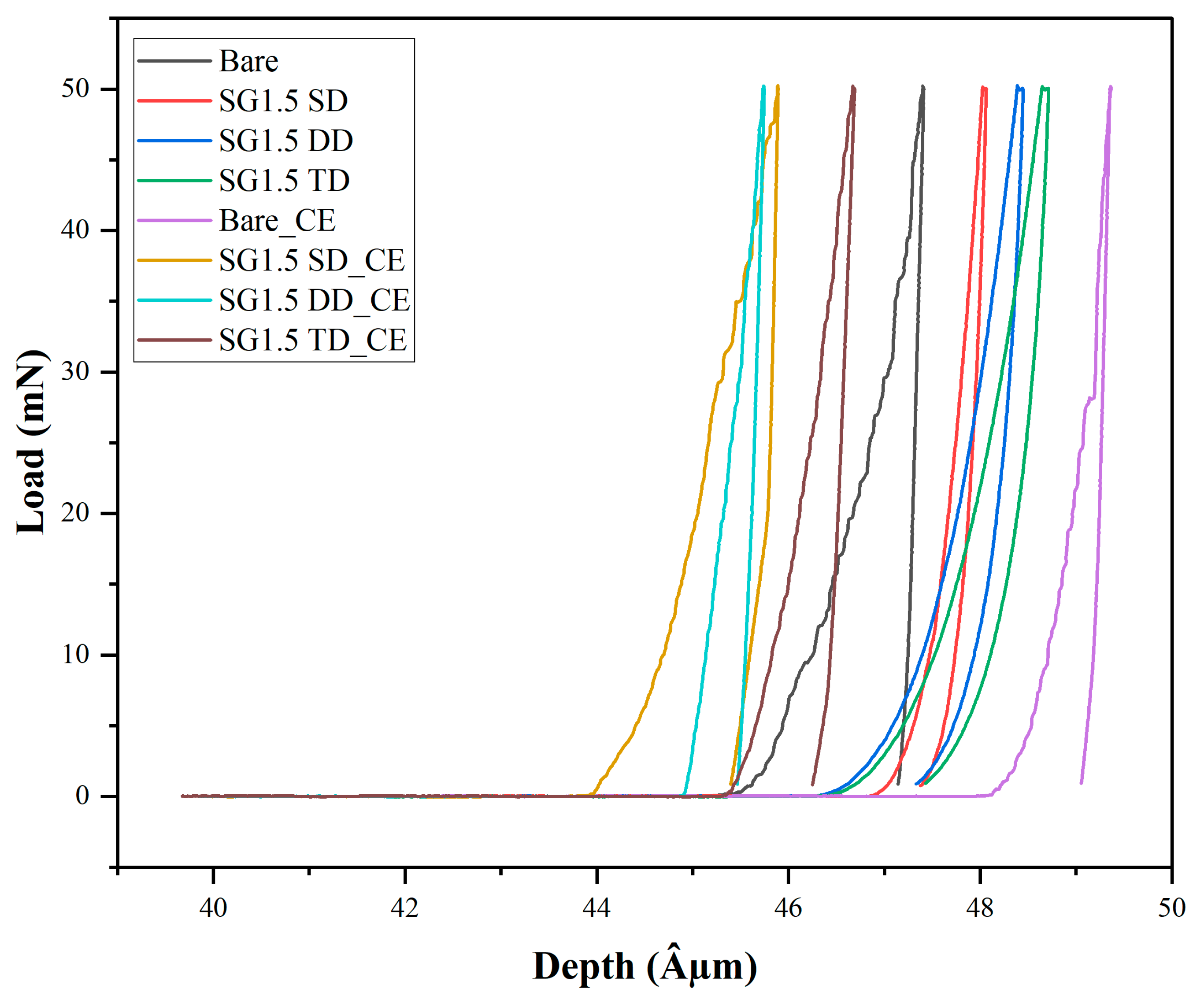
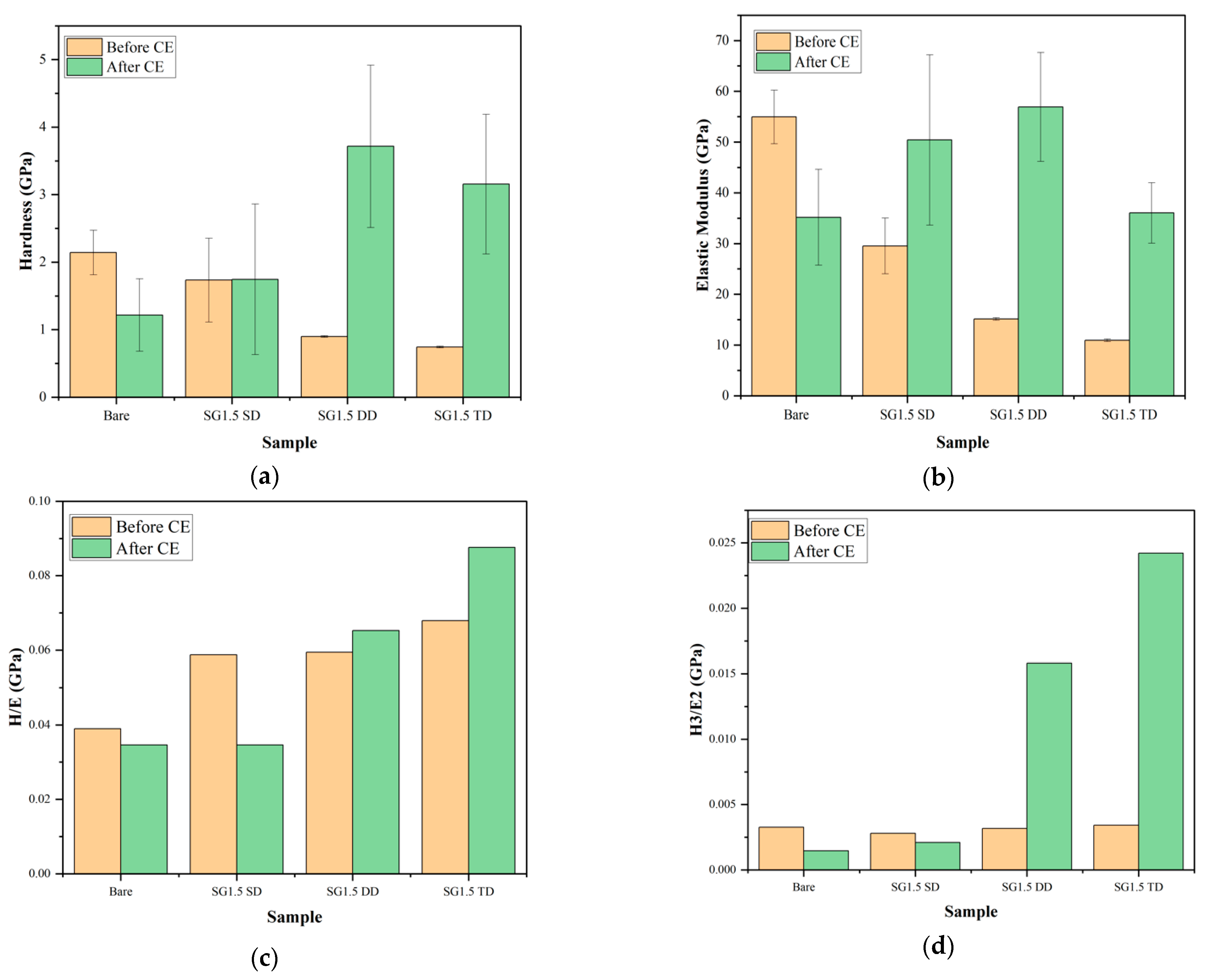
4.7. Nanoindentation Measurements

Effect of Cavitation Erosion on Nanoindentation Results

Nanoindentation measurements have shown promise as a technique for evaluating CER. Table 4 displays the ranking of the materials being studied in terms of their cavitation erosion resistance (CER), as determined from our earlier investigation into cavitation erosion [57].
Figure 8 and Table 5 reveal the findings of nanoindentation measurements taken before and after cavitation tests, which is a new technique for the cavitation erosion testing of thin films.
The results indicate that. following the cavitation tests, there was an increase in hardness for the coatings of varying thickness, whereas for the bare samples, there was a decrease in hardness. This could be attributed to the higher load-bearing capacity of the thicker coatings, resulting in an increase in their hardness. Moreover, the coatings may have acted as a barrier, hindering the penetration of the corrosive medium, thereby reducing material loss and increasing hardness. Additionally, the dynamic impact of the cavitation bubbles may have led to strain hardening in the coating. In contrast, the decrease in hardness for the bare samples may be due to the material loss and pitting induced by the cavitation process.
The H/E and H3/E2 ratios, which are indicators of a material’s sensitivity to elastic strain failure and resistance to plastic deformation, respectively, can potentially be used to determine a film’s CER (Figure 9c,d; Table 5). High H/E and H3/E2 ratios suggest that a material exhibits highly elastic behaviour and strong resistance to plastic deformation, resulting in greater CER. The high value of the H3/E2 coefficient is mainly responsible for the fracture toughness of thin films. The SG1.5 (SD, DD, TD) coatings had a higher H3/E2 ratio than bare AA2024-T3, indicating that they are more resistant to cavitation erosion than AA2024-T3 alone. Lower H/E values may lead to the formation of large pits more easily and quickly due to work hardening and the formation of microcracks in the hardened surface layer, resulting in greater cavitation erosion resistance. These observations are supported by the results of the normalized CER analysis [57].

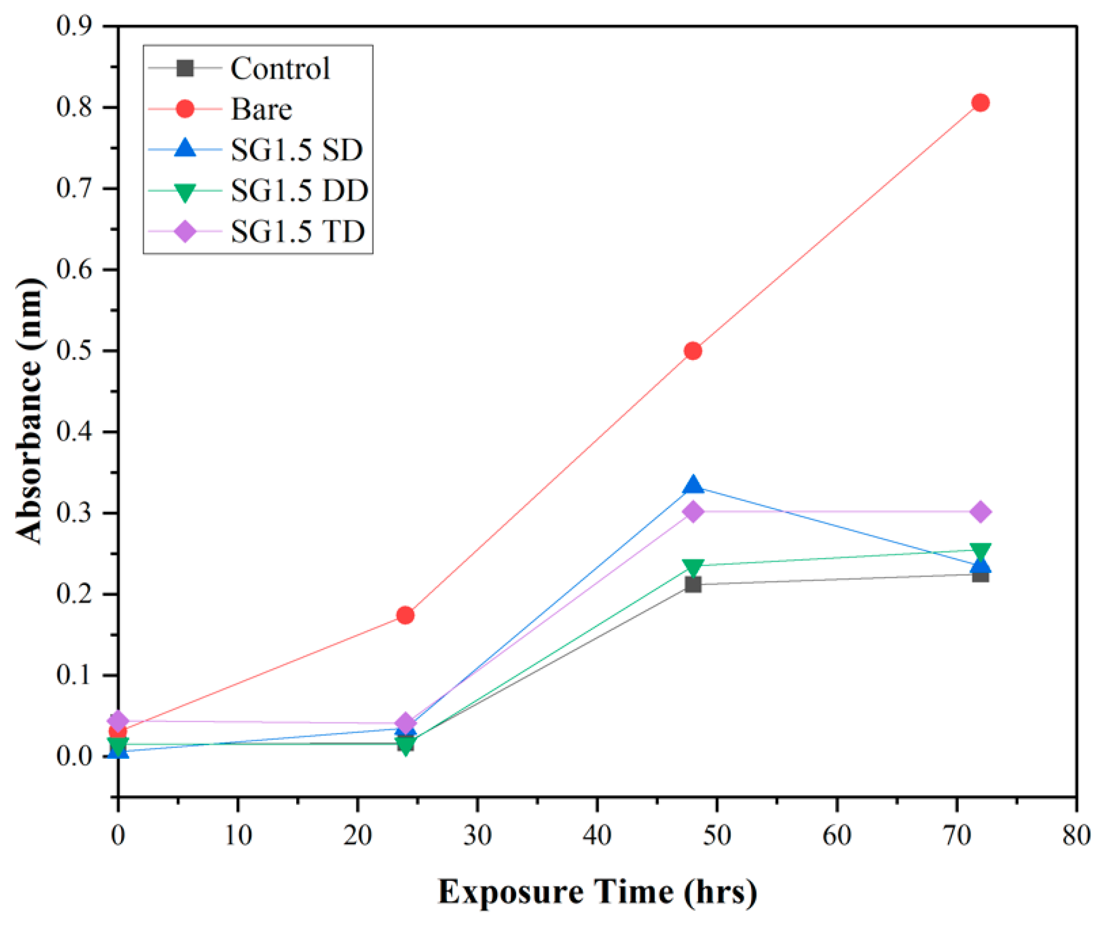
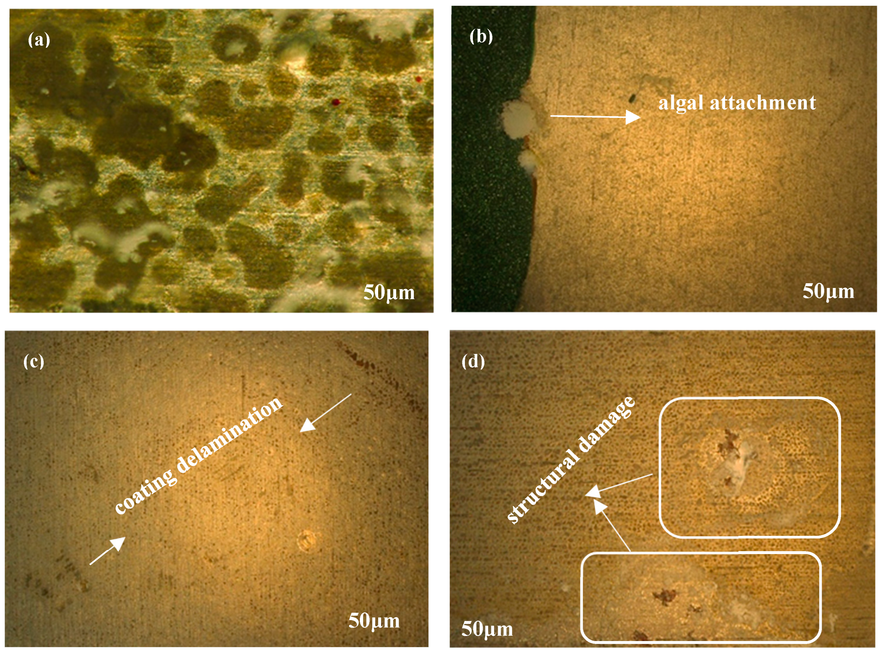
4.8. Antifouling Activity

Based on the results of the experiment (as shown in Figure 10), it was found that bare metal surfaces had much higher levels of adherence and growth of microalgae (Phaeodactylum tricornutum) compared to sol–gel coated substrates. The OD (absorbance as mentioned in Figure 10) measurements of the uncoated metal substrate increased from 0.031 at 0 h to 0.8 after 72 h of incubation, indicating the ability of microalgae to attach and develop on the surface over time. In contrast, the sol–gel coated substrates had lower OD values, with SG1.5 DD showing the lowest OD value over three days. This demonstrates that the sol–gel coating was effective in preventing the attachment and growth of microalgae, unlike the uncoated substrate.
The microscopic examination results support the OD measurements as they indicate that the coated substrates had a lower rate of bacterial adhesion and biofilm formation than the uncoated surfaces, which showed the highest rate of marine bacteria adherence and subsequent biofilm development. As shown in Figure 11, almost all of the microalgae adhered to the uncoated samples (control), while the percentage decreased to around 70% on the coated substrates. This suggests that the sol–gel coatings effectively prevented microalgae from attaching to and adhering to the surface. Furthermore, while microalgae were observed on the single-coated sample (SG1.5 SD), fewer microalgae were found compared to the uncoated sample. Interestingly, no microalgae were detected on the double-coated substrate (SG1.5 DD), indicating that the double coating was more effective in preventing microalgae attachment and growth on the surface. However, some structural damage and a small amount of coating delamination were observed in SG1.5 TD.

5. Conclusions

Aluminium alloys are commonly used to make various components and are considered a structural metal with moderate resistance to cavitation erosion. To prevent wear and erosion, the use of organically modified sol–gel coatings is being proposed as a promising solution that is easy to apply in industrial settings. The aims of this study were to investigate the antifouling properties of the developed sol–gel coatings and analyse the effects of coating thickness on properties linked to cavitation erosion resistance.
In this study, a sol–gel coating called MAPTMS-ZPO was applied to the surface of the alloy using a dip-coating technique with three different thicknesses of 2, 4, and 6 μm. The adhesion of the coating to the substrate was assessed using cross-cut adhesion and scratch tests, which revealed the strong adhesion of the coating to the AA2024-T3 substrate. This is important for long-term durability as the coating is less likely to peel off or delaminate from the substrate. Additionally, the roughness values of the coated samples were lower than those of the uncoated samples before the cavitation test, which is significant as surface roughness plays a crucial role in erosion resistance.
Furthermore, the sol–gel coating demonstrated highly elastic behaviour and resistance to plastic deformation due to its chemical composition, which provides a protective barrier to the metal substrate. The efficiency of the coatings in preventing biofouling was evaluated using a type of marine microorganism called Phaeodactylum tricornutum, and the sol–gel coating was found to be most effective in preventing the attachment and growth of microalgae.
The microscopic examination supported the OD measurements, showing that the uncoated surfaces had the highest rate of marine bacteria adhesion and subsequent biofilm development, while the coated substrates showed a decrease in bacterial adhesion and biofilm formation. These findings suggest that sol–gel coatings could be an effective means of preventing biofouling on marine surfaces.

Author Contributions

Conceptualization, M.H. and E.F.T.; Methodology, M.H.; Validation, M.H. and A.C.N.; Formal analysis, M.H. and J.M.; Investigation, M.H., M.M., J.M. and A.C.N.; Resources, B.D.; Writing—original draft, M.H.; Writing—review & editing, M.M., J.M., A.C.N., Y.K., B.D. and E.F.T.; Supervision, Y.K., B.D. and E.F.T.; Funding acquisition, M.H. All authors have read and agreed to the published version of the manuscript.

Funding

The research is funded by the Irish Research Council Government of Ireland Postgraduate Scholarship under Project ID GOIPG/2021/24.

Informed Consent Statement

Not applicable.

Data Availability Statement

The data presented in this study are available on request from the corresponding author.

Conflicts of Interest

The authors declare no conflict of interest.

References

  1. Yang, H.; Guo, X.; Chen, R.; Liu, Q.; Liu, J.; Yu, J.; Lin, C.; Wang, J.; Zhang, M. Enhanced anti-biofouling ability of polyurethane anti-cavitation coating with ZIF-8: A comparative study of various sizes of ZIF-8 on coating. Eur. Polym. J. 2021, 144, 110212. [Google Scholar] [CrossRef]
  2. Liang, L.; Pang, Y.; Tang, Y.; Zhang, H.; Liu, H.; Liu, Y. Combined wear of slurry erosion, cavitation erosion, and corrosion on the simulated ship surface. Adv. Mech. Eng. 2019, 11, 1687814019834450. [Google Scholar] [CrossRef]
  3. Shchukin, D.G.; Skorb, E.; Belova, V.; Möhwald, H. Ultrasonic cavitation at solid surfaces. Adv. Mater. 2011, 23, 1922–1934. [Google Scholar] [CrossRef] [PubMed]
  4. Plesset, M.S.; Chapman, R.B. Collapse of an initially spherical vapour cavity in the neighbourhood of a solid boundary. J. Fluid Mech. 1971, 47, 283–290. [Google Scholar] [CrossRef]
  5. Krefting, D.; Mettin, R.; Lauterborn, W. High-speed observation of acoustic cavitation erosion in multibubble systems. Ultrason. Sonochemistry 2004, 11, 119–123. [Google Scholar] [CrossRef] [PubMed]
  6. Dang, H.; Lovell, C.R. Microbial surface colonization and biofilm development in marine environments. Microbiol. Mol. Biol. Rev. 2016, 80, 91–138. [Google Scholar] [CrossRef]
  7. Francolini, I.; Vuotto, C.; Piozzi, A.; Donelli, G. Antifouling and antimicrobial biomaterials: An overview. Apmis 2017, 125, 392–417. [Google Scholar] [CrossRef]
  8. Mooss, V.A.; Hamza, F.; Zinjarde, S.S.; Athawale, A.A. Polyurethane films modified with polyaniline-zinc oxide nanocomposites for biofouling mitigation. Chem. Eng. 2019, 359, 1400–1410. [Google Scholar] [CrossRef]
  9. Banerjee, I.; Pangule, R.C.; Kane, R.S. Antifouling coatings: Recent developments in the design of surfaces that prevent fouling by proteins, bacteria, and marine organisms. Adv. Mater. 2011, 23, 690–718. [Google Scholar] [CrossRef]
  10. Xie, Q.; Pan, J.; Ma, C.; Zhang, G. Dynamic surface antifouling: Mechanism and systems. Soft Matter 2019, 15, 1087–1107. [Google Scholar] [CrossRef]
  11. Magin, C.M.; Cooper, S.P.; Brennan, A.B. Non-toxic antifouling strategies. Mater. Today 2010, 13, 36–44. [Google Scholar] [CrossRef]
  12. Lu, Y.; Yin, Y.; Mayers, B.T.; Xia, Y. Modifying the surface properties of superparamagnetic iron oxide nanoparticles through a sol−gel approach. Nano Lett. 2002, 2, 183–186. [Google Scholar] [CrossRef]
  13. Ni, M.; Leung, M.K.; Leung, D.Y.; Sumathy, K.J.R. A review and recent developments in photocatalytic water-splitting using TiO2 for hydrogen production. Renew. Sustain. Energy Rev. 2007, 11, 401–425. [Google Scholar] [CrossRef]
  14. Voulvoulis, N.; Scrimshaw, M.D.; Lester, J.N. Comparative environmental assessment of biocides used in antifouling paints. Chemosphere 2002, 47, 789–795. [Google Scholar] [CrossRef] [PubMed]
  15. Zheludkevich, M.; Serra, R.; Montemor, M.; Salvado, I.M.; Ferreira, M.J.S. Corrosion protective properties of nanostructured sol–gel hybrid coatings to AA2024-T3. Surf. Coat. 2006, 200, 3084–3094. [Google Scholar] [CrossRef]
  16. ANNEX. TO REACH—Conditions of Restriction. 1907. 2006. Available online: https://osha.europa.eu/en/legislation/directives/regulation-ec-no-1907-2006-of-the-european-parliament-and-of-the-council (accessed on 26 March 2023).
  17. Chambers, L.D.; Stokes, K.R.; Walsh, F.C.; Wood, R. Modern approaches to marine antifouling coatings. Surf. Coat. 2006, 201, 3642–3652. [Google Scholar] [CrossRef]
  18. Fahim, J.; Hadavi, S.; Ghayour, H.; Tabrizi, S.H. Cavitation erosion behavior of super-hydrophobic coatings on Al5083 marine aluminum alloy. Wear 2019, 424, 122–132. [Google Scholar] [CrossRef]
  19. Fang, Z.; Cao, J.; Guan, Y. Corrosion Control Technologies for Aluminum Alloy Vessel; Springer: Singapore, 2020. [Google Scholar]
  20. Osborne, J. Observations on chromate conversion coatings from a sol–gel perspective. Prog. Org. Coat. 2001, 41, 280–286. [Google Scholar] [CrossRef]
  21. Wang, H.; Akid, R. A room temperature cured sol–gel anticorrosion pre-treatment for Al 2024-T3 alloys. Corros. Sci. 2007, 49, 4491–4503. [Google Scholar] [CrossRef]
  22. Sanchez, C.; Ribot, F.; Lebeau, B. Molecular design of hybrid organic-inorganic nanocomposites synthesized via sol-gel chemistry. J. Mater. Chem. 1999, 9, 35–44. [Google Scholar] [CrossRef]
  23. Sharp, K. Inorganic/organic hybrid materials. Adv. Mater. 1998, 10, 1243–1248. [Google Scholar] [CrossRef]
  24. Ashrafi-Shahri, S.; Ravari, F.; Seifzadeh, D. Smart organic/inorganic sol-gel nanocomposite containing functionalized mesoporous silica for corrosion protection. Prog. Org. Coat. 2019, 133, 44–54. [Google Scholar] [CrossRef]
  25. Chou, T.; Chandrasekaran, C.; Cao, G. Sol-gel-derived hybrid coatings for corrosion protection. J. Sol-Gel Sci. Technol. 2003, 26, 321–327. [Google Scholar] [CrossRef]
  26. Mackenzie, J.; Bescher, E. Some factors governing the coating of organic polymers by sol-gel derived hybrid materials. J. Sol-Gel Sci. Technol. 2003, 27, 7–14. [Google Scholar] [CrossRef]
  27. Hwang, J.M.; Yeo, C.S.; Kim, Y. Preparation and Characterization of Sol-Gel Derived SiO2-TiO2-PDMS Composite Films. Bull. Korean Chem. Soc. 2001, 22, 1366–1370. [Google Scholar]
  28. Du, Y.J.; Damron, M.; Tang, G.; Zheng, H.; Chu, C.-J.; Osborne, J.H. Inorganic/organic hybrid coatings for aircraft aluminum alloy substrates. Prog. Org. Coat. 2001, 41, 226–232. [Google Scholar]
  29. Hofacker, S.; Mechtel, M.; Mager, M.; Kraus, H. Sol–gel: A new tool for coatings chemistry. Prog. Org. Coat. 2002, 45, 159–164. [Google Scholar] [CrossRef]
  30. Suárez-Vega, A.; Agustín-Sáenz, C.; O’Dell, L.A.; Brusciotti, F.; Somers, A.; Forsyth, M. Properties of hybrid sol-gel coatings with the incorporation of lanthanum 4-hydroxy cinnamate as corrosion inhibitor on carbon steel with different surface finishes. Appl. Surf. Sci. 2021, 561, 149881. [Google Scholar] [CrossRef]
  31. Mozammel, M.; Khajeh, M.; Ilkhechi, N.N. Effect of surface roughness of 316 L stainless steel substrate on the morphological and super-hydrophobic property of TiO2 thin films coatings. Silicon 2018, 10, 2603–2607. [Google Scholar] [CrossRef]
  32. Cullen, M.; O’Sullivan, M.; Kumar, A.M.; Sorour, A.A.; Duffy, B.; Oubaha, M. The role of the hydrolysis and zirconium concentration on the structure and anticorrosion performances of a hybrid silicate sol-gel coating. J. Sol-Gel Sci. Technol. 2018, 86, 553–567. [Google Scholar] [CrossRef]
  33. MacHugh, E.; Cullen, M.; Kaworek, A.; Duffy, B.; Oubaha, M. The effect of curing and zirconium content on the wettability and structure of a silicate hybrid sol-gel material. J. Non-Cryst. Solids 2019, 525, 119658. [Google Scholar] [CrossRef]
  34. Schubert, U. Organofunctional metal oxide clusters as building blocks for inorganic-organic hybrid materials. J. Sol-Gel Sci. Technol. 2004, 31, 19–24. [Google Scholar] [CrossRef]
  35. Wang, T.; Wang, X.; Zhang, Y.; Liu, L.; Xu, L.; Liu, Y.; Zhang, L.; Luo, Z.; Cen, K. Effect of zirconium (IV) propoxide concentration on the thermophysical properties of hybrid organic-inorganic films. J. Appl. Phys. 2008, 104, 013528. [Google Scholar] [CrossRef]
  36. Del Monte, F.; Cheben, P.; Grover, C.; Mackenzie, J. Preparation and optical characterization of thick-film zirconia and titania ormosils. J. Sol-Gel Sci. Technol. 1999, 15, 73–85. [Google Scholar] [CrossRef]
  37. Fedel, M.; Deflorian, F. Influence of a boiling water treatment on the electrochemical properties of a sol–gel film on AA1050. Trans. IMF 2015, 93, 313–320. [Google Scholar] [CrossRef]
  38. Fedel, M. Effect of sol–gel layers obtained from GLYMO/MTES mixtures on the delamination of a cataphoretic paint on AA1050. J. Coat. Technol. Res. 2017, 14, 425–435. [Google Scholar] [CrossRef]
  39. Naderi, R.; Fedel, M.; Urios, T.; Poelman, M.; Olivier, M.G.; Deflorian, F. Optimization of silane sol–gel coatings for the protection of aluminium components of heat exchangers. Surf. Interface Anal. 2013, 45, 1457–1466. [Google Scholar] [CrossRef]
  40. Tiringer, U.; Van Dam, J.; Abrahami, S.; Terryn, H.; Kovač, J.; Milošev, I.; Mol, J. Scrutinizing the importance of surface chemistry versus surface roughness for aluminium/sol-gel film adhesion. Surf. Interfaces 2021, 26, 101417. [Google Scholar] [CrossRef]
  41. Lebeau, B.; Innocenzi, P. Hybrid materials for optics and photonics. Chem. Soc. Rev. 2011, 40, 886–906. [Google Scholar] [CrossRef]
  42. Ferreira, R.; André, P.; Carlos, L. Organic–inorganic hybrid materials towards passive and active architectures for the next generation of optical networks. Opt. Mater. 2010, 32, 1397–1409. [Google Scholar] [CrossRef]
  43. Elmaghrum, S.; Gorin, A.; Kribich, R.K.; Corcoran, B.; Copperwhite, R.; McDonagh, C.; Oubaha, M. Development of a sol–gel photonic sensor platform for the detection of biofilm formation. Sens. Actuators B 2013, 177, 357–363. [Google Scholar] [CrossRef]
  44. Oubaha, M.; Kavanagh, A.; Gorin, A.; Bickauskaite, G.; Byrne, R.; Farsari, M.; Winfield, R.; Diamond, D.; McDonagh, C.; Copperwhite, R. Graphene-doped photo-patternable ionogels: Tuning of conductivity and mechanical stability of 3D microstructures. J. Mater. Chem. 2012, 22, 10552–10559. [Google Scholar] [CrossRef]
  45. Ghosh, G.; Sidpara, A.; Bandyopadhyay, P. Understanding the role of surface roughness on the tribological performance and corrosion resistance of WC-Co coating. Surf. Coat. 2019, 378, 125080. [Google Scholar] [CrossRef]
  46. Wang, A.; Rack, H. Dry sliding wear in 2124 Al-SiCw/17-4 PH stainless steel systems. Wear 1991, 147, 355–374. [Google Scholar] [CrossRef]
  47. Bayer, R.; Sirico, J. The influence of surface roughness on wear. Wear 1975, 35, 251–260. [Google Scholar] [CrossRef]
  48. Walter, R.; Kannan, M. Influence of surface roughness on the corrosion behaviour of magnesium alloy. Mater. Des. 2011, 32, 2350–2354. [Google Scholar] [CrossRef]
  49. Hong, T.; Nagumo, M. Effect of surface roughness on early stages of pitting corrosion of type 301 stainless steel. Corros. Sci. 1997, 39, 1665–1672. [Google Scholar] [CrossRef]
  50. Cabrini, M.; Cigada, A.; Rondell, G.; Vicentini, B. Effect of different surface finishing and of hydroxyapatite coatings on passive and corrosion current of Ti6Al4V alloy in simulated physiological solution. Biomaterials 1997, 18, 783–787. [Google Scholar] [CrossRef]
  51. Li, W.; Li, D. Influence of surface morphology on corrosion and electronic behavior. Acta Mater. 2006, 54, 445–452. [Google Scholar] [CrossRef]
  52. Krzak-Roś, J.; Filipiak, J.; Pezowicz, C.; Baszczuk, A.; Miller, M.; Kowalski, M.; Będziński, R. The effect of substrate roughness on the surface structure of TiO2, SiO2, and doped thin films prepared by the sol-gel method. Acta Bioeng. Biomech. 2009, 11, 21–29. [Google Scholar]
  53. Zhao, H.; Yu, M.; Liu, J.; Li, S.; Xue, B.; Liang, M. Effect of surface roughness on corrosion resistance of sol-gel coatings on AA2024-T3 alloy. J. Electrochem. Soc. 2015, 162, C718. [Google Scholar] [CrossRef]
  54. Fernández-Hernán, J.; López, A.; Torres, B.; Rams, J. Influence of roughness and grinding direction on the thickness and adhesion of sol-gel coatings deposited by dip-coating on AZ31 magnesium substrates. A Landau–Levich equation revision. Surf. Coat. 2021, 408, 126798. [Google Scholar] [CrossRef]
  55. Wang, Y.; Zhu, X.; Lao, Y.; Lv, X.; Tao, Y.; Huang, B.; Wang, J.; Zhou, J.; Cai, Z. TiO2 nanoparticles in the marine environment: Physical effects responsible for the toxicity on algae Phaeodactylum tricornutum. Sci. Total Environ. 2016, 565, 818–826. [Google Scholar] [CrossRef]
  56. Liu, Z.; Tian, S.; Li, Q.; Wang, J.; Pu, J.; Wang, G.; Zhao, W.; Feng, F.; Qin, J.; Ren, L. Integrated dual-functional ORMOSIL coatings with AgNPs@ rGO nanocomposite for corrosion resistance and antifouling applications. ACS Sustain. Chem. Eng. 2020, 8, 6786–6797. [Google Scholar] [CrossRef]
  57. Hegde, M.; Kavanagh, Y.; Duffy, B.; Tobin, E.F. Abrasion and Cavitation Erosion Resistance of Multi-Layer Dip Coated Sol-Gel Coatings on AA2024-T3. Corros. Mater. Degrad. 2022, 3, 661–671. [Google Scholar] [CrossRef]
  58. ISO 15184:2020; Paints and Varnishes—Determination Of Film Hardness by Pencil Test. ISO: Geneva, Switzerland, 2020.
  59. ASTM D3359-09; Standard Test Methods for Measuring Adhesion by Tape Test. ASTM: West Conshohocken, PA, USA, 2023.
Figure 1. Graph showing thickness of single-, double-, and triple-coated samples. Values represent average of n = 3 ± SD.
Eng 04 00081 g001
Figure 2. ATR-FTIR spectra of SG1.5 single-, double-, and triple-coated samples.
Eng 04 00081 g002
Figure 3. Hydrophobicity of single-, double-, and triple-coated samples. Values represent average of n = 3 ± SD with different subscript letter representing significant difference (p < 0.05).
Eng 04 00081 g003
Figure 4. Hardness of the thickness of coatings.
Eng 04 00081 g004
Figure 5. Adhesion of the different coating thicknesses.
Eng 04 00081 g005
Figure 6. Microscopic images of cross-cut test: (a) SG1.5 SD; (b) SG1.5 DD; (c) SG1.5 TD.
Eng 04 00081 g006
Figure 7. Graph showing surface roughness of the coatings before and after cavitation erosion test. Values represent average of n = 3 ± SD. In each group (before and after CE), different subscript letters represent significant difference (p < 0.05).
Eng 04 00081 g007
Figure 8. Loading–unloading nanoindentation curves estimated on the films and reference AA2024-T3 surface before and after cavitation erosion tests (marked as “CE”).
Eng 04 00081 g008
Figure 9. (a) Hardness, (b) Young’s modulus values, (c) H/E ratio, and (d) H3/E2 ratio for the uncoated substrate and the SG1.5 coating. Values represent average of n = 5 ± SD.
Eng 04 00081 g009
Figure 10. Optical density vs. exposure time of coated and uncoated substrates (n = 1).
Eng 04 00081 g010
Figure 11. Microscopic images of Phaeodactylum tricornutum growth on (a) bare sample, (b) SG1.5 SD, (c) SG1.5 DD, and (d) SG1.5 TD.
Eng 04 00081 g011
Table 1. Sample name for material formulation.
SubstrateCoating Reference
MAPTMS + ZPO + 1.5% HMDI single dipSG1.5 SD
MAPTMS + ZPO + 1.5% HMDI double dipSG 1.5 DD
MAPTMS + ZPO + 1.5% HMDI triple dipSG 1.5 TD
Table 2. Composition of concentrated solutions to prepare synthetic sea water.
SaltsConcentration (Dissolved in 2 L of Deionized Water)
NaCl52.8 g
KCl1680 mg
CaCl2·2H2O3340 mg
MgCl2·6H2O9200 mg
MgSO4·7H2O11,160 mg
NaHCO3340 mg
H3BO360 mg
Table 3. Mass loss results obtained for bare and SG1.5 samples after cavitation erosion test [57].
Sample Bare SG1.5 SD SG1.5 DD SG1.5 TD
Time (min) Average Cumulative Mass Loss (mg)
Start0000
10.5000
31.00.20.60.3
51.80.50.80.6
72.40.631.10.8
92.80.81.231.22
113.51.01.41.38
Table 4. Investigated materials in increasing order of cavitation erosion resistance [57].
RankMaterials
1SG1.5 DD
2SG1.5 TD
3SG1.5 SD
4Bare
Table 5. Results of hardness (H), elastic modulus (E), elastic strain failure (H/E), and resistance to plastic deformation H3/E2 measured on the surface of samples before and after (marked as “CE”) cavitation tests.
ParameterBefore Cavitation TestAfter Cavitation Test
BareSG1.5 SDSG1.5 DDSG1.5 TDBareSG1.5 SDSG1.5 DDSG1.5 TD
H2.141.730.890.741.211.743.713.15
E54.9529.5315.1210.9437.1750.4156.9336.03
H/E0.0380.0590.0590.0670.030.0350.0650.08
H3/E23.2 × 10−35.9 × 10−33.1 × 10−33.4 × 10−31.3 × 10−32.0 × 10−39.8 × 10−30.024
Disclaimer/Publisher’s Note: The statements, opinions and data contained in all publications are solely those of the individual author(s) and contributor(s) and not of MDPI and/or the editor(s). MDPI and/or the editor(s) disclaim responsibility for any injury to people or property resulting from any ideas, methods, instructions or products referred to in the content.

