1. Introduction
The global request for electrical energy in the world is growing daily as the standard of living improves, while the stock of fossil fuels is decreasing. It is one of the many problems caused by fossil energies that have prompted the world to seek and invest in alternative energy sources [
1]. Solar, wind and hydraulic energy are the most common inexhaustible and dependable energy sources. Solar energy has several applications, including heat supply via thermodynamic solar systems [
2], hot water production via solar water heaters [
3] and electricity generation via PV systems [
4].
The function of PV systems is to absorb sunlight and convert it into electricity through the PV cells [
5]. It is the most practical clean technology due to its operational nature and simplicity. However, there are some problems associated with these systems in terms of their efficiency: the operating point of the PV panel shifts from open to short-circuit conditions. Thus, in order to operate at the MPP, an MPPT controller is usually required. Different algorithms have been developed and implemented by researchers in this context. Among these algorithms, we note Perturb and Observe (P&O) [
6,
7]. Its principle consists in disturbing the voltage of the PV array and comparing the instantaneous power with that of the previous disturbance. Then, the direction of the disturbance depends on the increase or decrease in power. Incremental conductance (INC) [
8,
9] utilizes the slope of the P˗V curve of the PV array characteristics to determine the MPP. This slope is equal to zero at the MPP, positive to its left and negative to its right. The process of Fuzzy Logic (FL) control [
10] consists in taking an input value and making it undergo a fuzzification (first step); then, it is treated by an inference engine (second step), and lastly, it undergoes a defuzzification stage.
In PV systems, the presence of an inverter is also mandatory to switch the DC voltage at the exit of the converter into an AC voltage to supply the alternating load or grid. Multilevel inverters have many advantages compared to two-level inverters. They produce a reduced total harmonic distortion (THD) with a low switching frequency and an optimized output voltage. Over the years, a variety of multilevel inverter topologies have been developed. Citing the classical ones, such as Neutral Point Clamped (NPC) [
11,
12], Flying Capacitor (FC) [
13,
14] and Cascaded H-bridge (CHB) [
15], these inverters use a large number of components and even more than one DC source. For those reasons, researchers have developed new topologies of multilevel inverters such as Packed U-Cells (PUC) [
16,
17,
18], which needs a low number of passive and active switches and provides a high number of levels without using filters or sensors, and Split Packed U-Cells (SPUC) [
19], which is able to combine capacitors together, and also uses a small number of components with an uncomplicated PWM control technique. The SPUC inverter is very competitive in PV systems in standalone mode [
20,
21], as well as in grid-connected mode as published in [
22,
23].
In this work, a new MPPT controller based on the Hysteresis technique has been proposed to control the boost converter DC/DC in order to achieve the MPP of the PV array. The five-level SPUC inverter DC/AC has been chosen in this paper with a PWM controller to supply the load with a high-quality AC voltage. The presented standalone PV system has been tested and simulated under Standard Test Conditions (STC) and under different irradiation conditions to evaluate the performance of the proposed technique.
The rest of the document is organized as follows:
Section 2 explains the proposed MPPT algorithm,
Section 3 is dedicated to the description of the components of the proposed PV system,
Section 4 discusses simulation results, and
Section 5 is dedicated to the conclusion.
2. The Proposed MPPT Technique Based on the Hysteresis Control
The INC algorithm is among the most popular techniques used for MPPT of PV systems. It has a simple process of tracking and does not require a large amount of memory space for implementation. The MPP is tracked by detecting the slope of the P-V curve of the PV panel and then searching for the peak of this curve. The MPP is only reached when its value is equal to zero, as shown in Equation (1):
where dP is the variation of the output power of the PV panel and dV is the variation of the output voltage of the PV panel.
The INC algorithm calculates the instantaneous conductance I/V and the incremental conductance dI/dV to determine the MPP. By deriving Equation (1), the following equations are obtained:
The previous equations provide the three cases of the P-V curve: Equation (2) means that the PV panel is running at MPP, Equation (3) means that the PV panel is running to the left of MPP, and Equation (4) means that the PV panel is running to the right of the MPP.
However, this method has some drawbacks; it makes oscillations around MPP and has no regular adaptation. Therefore, it requires an auxiliary controller to enhance its efficiency. PWM controller is added to the INC by authors in [
20], which quickly tracks the MPP in a standalone PV system even under the change of irradiation, but the oscillations still appear. A Proportional Integral (PI) controller is adopted for the variable step INC algorithm in [
24]; it can track the MPP faster and more precisely.
This work proposes to associate a Hysteresis Band controller to the INC. This combination ensures improved tracking performances either at the level of speed and accuracy or at the level of oscillation reduction.
In effect, as previously explained, the INC allows for the identification the MPP, after which the hysteresis improves the tracking accuracy and reduces oscillations around it.
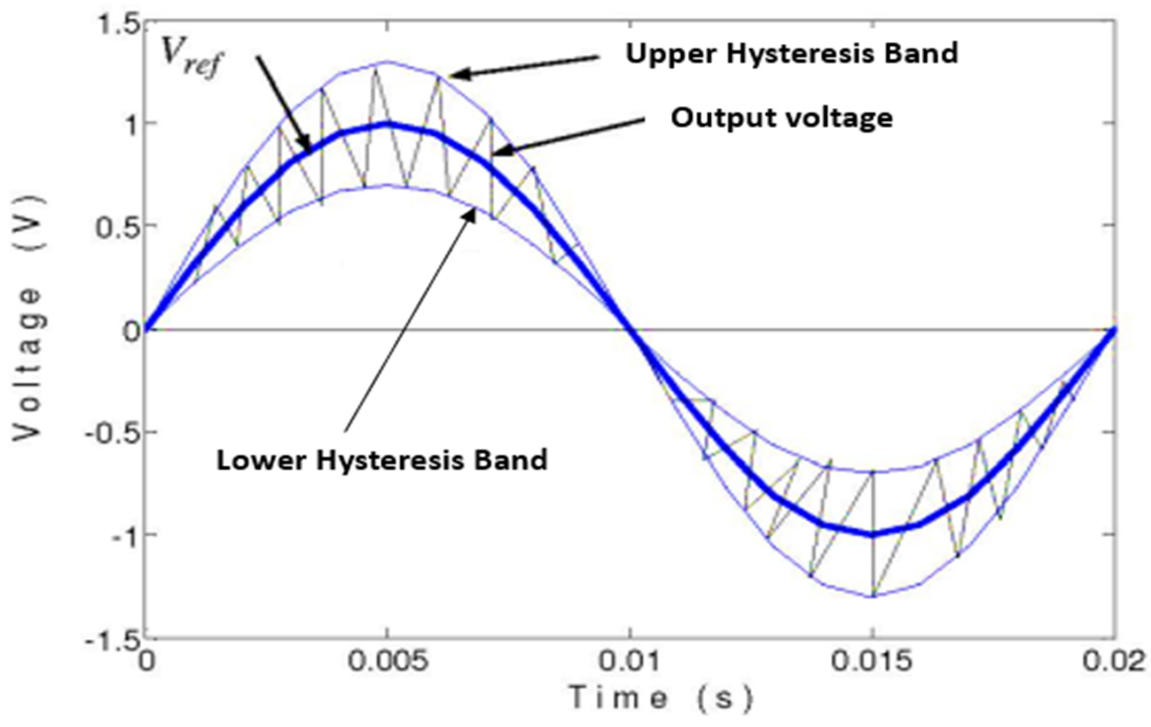
The hysteresis has the advantage of controlling the voltage delivered by the INC block and not the duty cycle. The value of the measured voltage is directly compared to the reference voltage. The voltage error is then immediately compared to the hysteresis band to provide switching pulses for the boost converter.
This method is designed to control the switch of the boost converter to ramp the voltage up and down in order to follow the reference voltage signal.
The error is the difference between the generated voltage and the desired voltage. It is used for controlling the boost converter switch. The maximum and minimum values of the error signal form the Upper and Lower Hysteresis band, respectively, are shown in
Figure 1.
where V
ref is the reference voltage, e
max presents the maximum value of the error, and e
min is the minimum value of the error signal.
The voltage must remain between the Upper and Lower Hysteresis Band. For this reason, when the real value of the voltage attains the Upper Hysteresis Band, the switch turns ON to enforce the voltage to decrease, and when it attains the Lower Hysteresis Band, the switch turns ON to enforce the voltage to increase.
3. The Studied Photovoltaic System
The components of the proposed PV system are presented and modeled in this section; the power is produced by a PV panel, connected to the boost converter in order to track the MPP and regulate the DC voltage. This component is connected to the SPUC5 inverter, which converts DC voltage into AC voltage in order to supply the load.
3.1. The PV Array
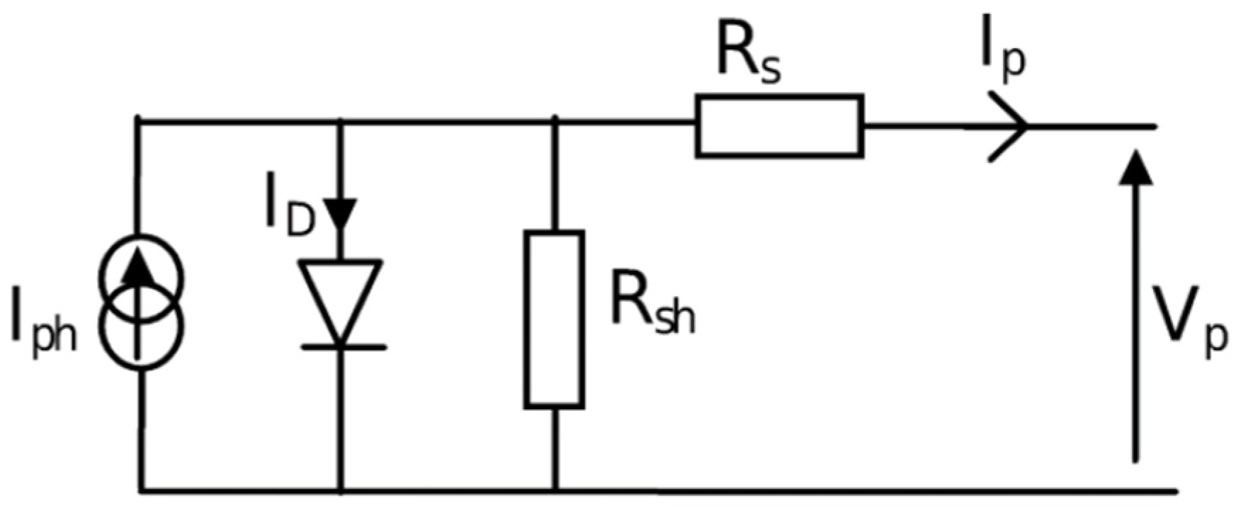
The PV panel is the source of the energy in every PV system. It is composed of several cells connected to each other. The general circuit of a PV cell is presented in
Figure 2 [
25].
The mathematical equation of the current generated by a PV panel constituted of N number of cells is described as follows:
where
with I
PV as the current generated by the PV panel, I
ph presenting the photo-current, I
S as the diode saturation current, q as the electron charge (q = 1.60217646 × 10
−19 C), V
P presenting the PV panel voltage, I
P as the PV panel current, R
s as the series resistance, γ as the ideality factor of the diode, K presenting the Boltzmann constant and its value as 1.3806503 × 10
−23 J/K, T as the temperature cell, R
sh presenting the parallel resistance, I
ph0 presenting the photo current measured under STC (G
STC = 1000 W/m
2 and T
STC = 25 °C are, respectively, the irradiation and the temperature at STC), K
i as the temperature coefficient of short circuit current, G as the irradiation, I
S0 as the saturation current under STC, T
STC and E
G presenting the band gap energy.
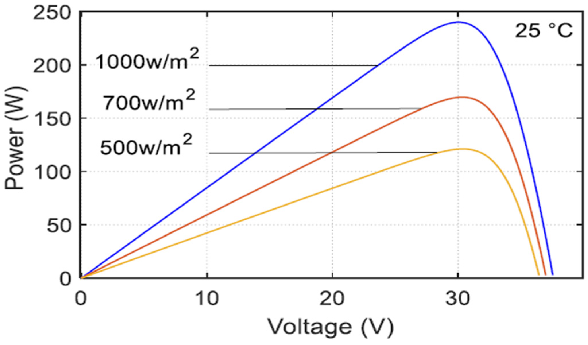
In this study, the authors chose SOLARIA S6M2G240 for reference of the PV module. The P-V curve of the latter under different irradiations is presented in
Figure 3.
Table 1 lists the parameters of the chosen PV panel at the STC.
3.2. DC/DC Boost Converter
A DC/DC conversion stage is needed in PV systems, after the PV array and before the inverter, in order to increase or decrease the DC voltage introduced by PV panels and to reach their maximum power point by controlling this converter with an MPPT controller [
26].
In our system, the DC/DC converter is a boost converter, which allows increasing the input voltage Vi according to the following equation:
where V
o presents the output voltage, and α is the duty cycle.
The used boost converter consists of a switch S, a diode D, an inductor L, and three Capacitors C1, C2 and C3 as shown in
Figure 4.
3.3. SPUC5 Inverter
In order to supply the load with AC voltage, we need to use an inverter; the SPUC5 is the topology chosen due to its efficiency. It is based on the combination of the PUC and the NPC technologies, which permits it to benefit from the advantages of both. On the one hand, it generates five voltage levels with only five switches (T1, T2, T3, T4 and T5), one DC source (E) and two capacitors (C1 and C2). On the other hand, it provides the possibility to join capacitors together.
The capacitor voltages are properly balanced using the PWM technique without the need for any PI regulators or filters.
Figure 5 shows the SPUC5 inverter scheme.
Before applying it to the proposed PV system, the SPUC5 inverter is verified with a constant 300 V DC source.
Table 2 shows the switching sequence of the SPUC5 inverter with the redundant state and the output voltage in each state. V
C1 and V
C2 are, respectively, the voltages of Capacitor 1 and Capacitor 2.
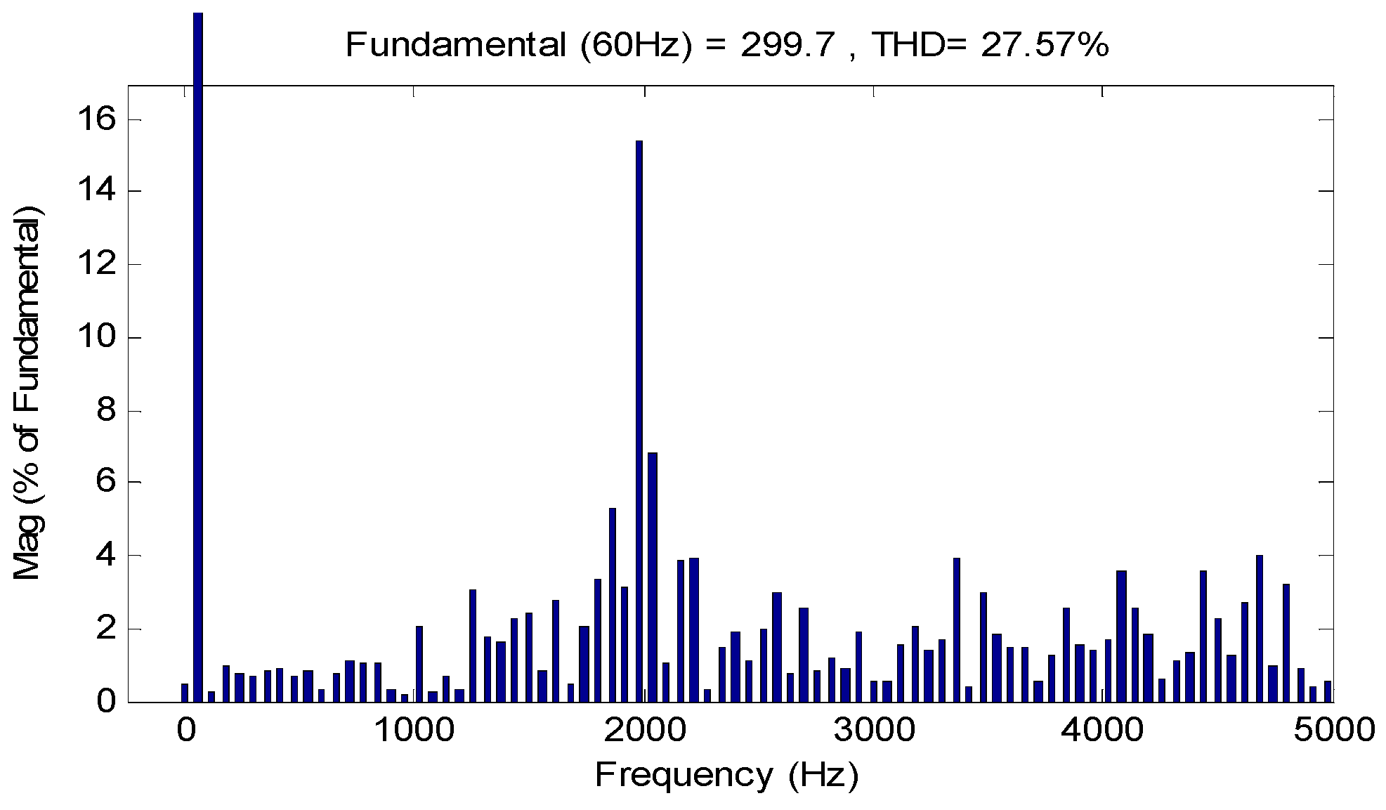
The output voltage is constituted of five levels: 300 V, 150 V, 0 V, −150 V and −300 V as shown in
Figure 6. The THD of the load voltage is presented in
Figure 7 (around 27.57%).
4. Simulation Results
The offered PV system has been modeled and simulated in the MATLAB/Simulink software under severe temperature and irradiation conditions, as shown in
Figure 8 and
Figure 9, in order to demonstrate the efficiency of the proposed MPPT technique, in particular, and the entire studied PV system in general.
At first [0,2 s], the PV panel is exposed to STC (1000 W/m2 of irradiation and 25 °C of temperature), then the temperature was increased to attain 39 °C with the same irradiation until 2.5 s; thereafter, the irradiation underwent an orthogonal decrease to reach 320 W/m2 at 3 s and remain stable until 5 s; after that, the irradiation suddenly changed to 660 W/m2 from 5 s to 7 s; beyond this period, the simulation continued with a temperature of 32 °C and an irradiation of 935 W/m2.
The parameters of the PV system during the simulation are listed in
Table 3.
4.1. Simulation Results of the Proposed PV System
Figure 10 shows the output power of the PV panel using the INC-HYS algorithm; the MPP is reached after a short simulation time; it is approximately 240 W for 1000 W/m
2 and 25 °C of temperature, which is in accordance with the characteristics of the PV module presented in the datasheet
Figure 3. As the temperature rises, the power decreases proportionally to the irradiation to reach approximately 70 W for 320 W/m
2 and 39 °C. In the irradiation of 660 W/m
2, the power decreases to quickly attain 150 W; after, in the last change in irradiations and temperature (respectively, 935 W/m
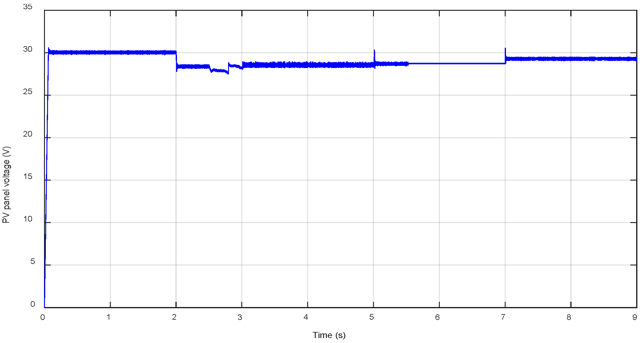
2 and 32 °C), the PV panel power increases to 220 W. These remarks validate the effectiveness of the proposed INC-HYS technique to reach the MPP rapidly and accurately even under difficult changing weather conditions. The same occurs for the PV panel voltage, as illustrated in
Figure 11, in the time interval of [0,2 s] under STC; the voltage value reaches 30 V after a short time, which is the value corresponding to the maximum power as shown in
Figure 3, then the voltage changes and takes the optimal value for each weather condition.
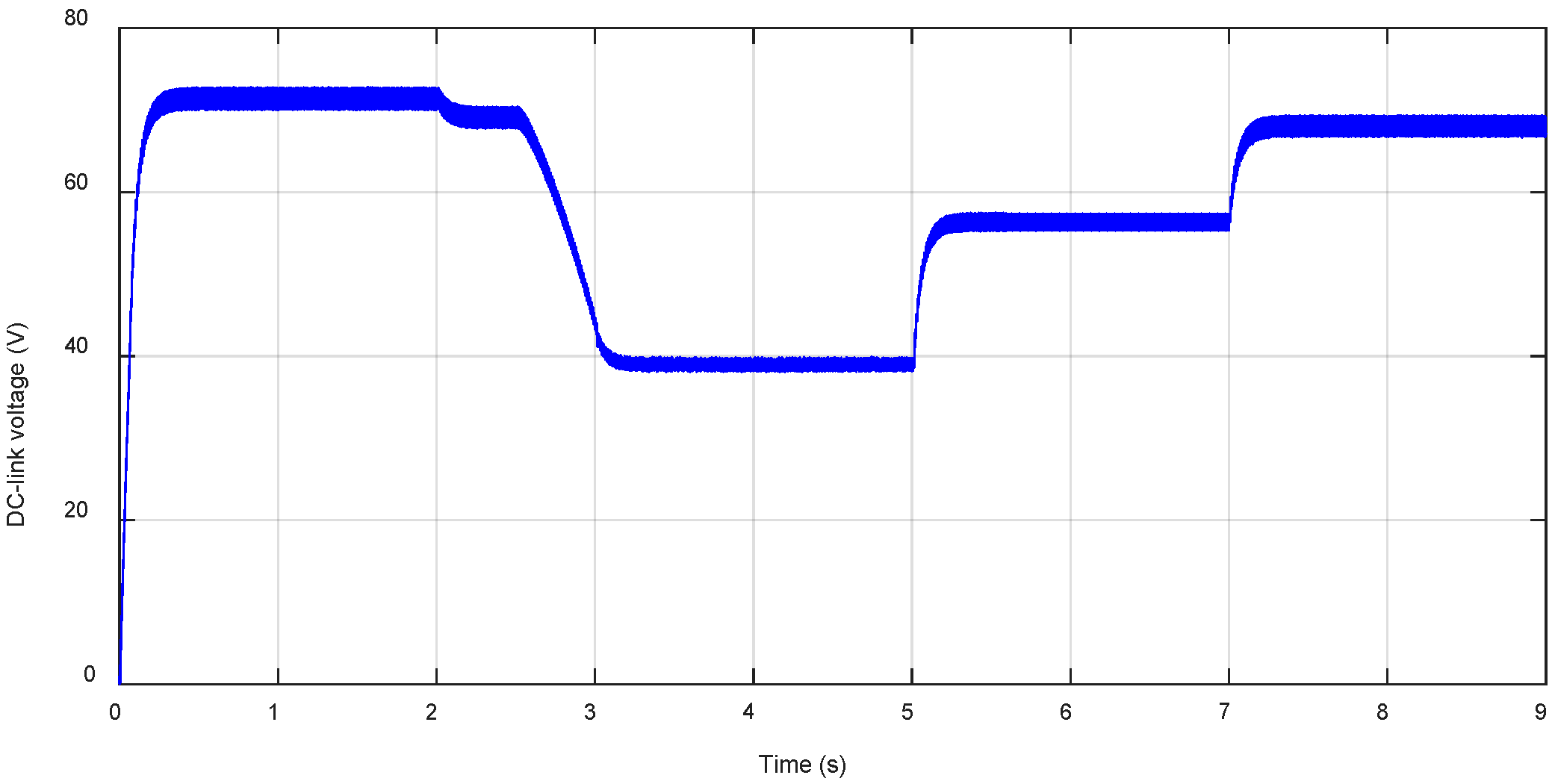
The DC-link voltage is shown in
Figure 12. It is well regulated and its values change according to the weather conditions.
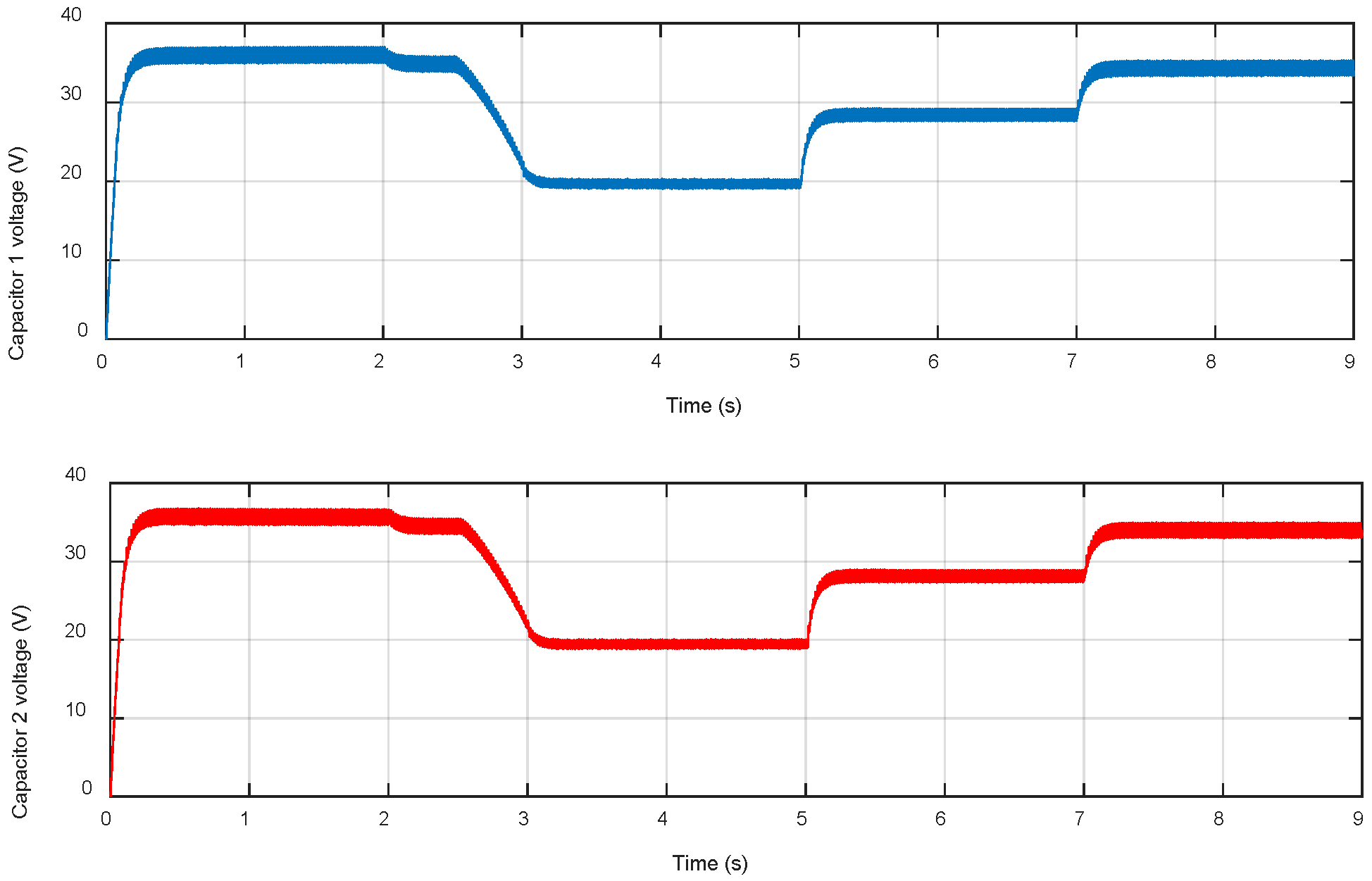
Figure 13 presents the SPUC5 capacitor voltages. They are properly controlled and maintained at half of the DC-link voltage.
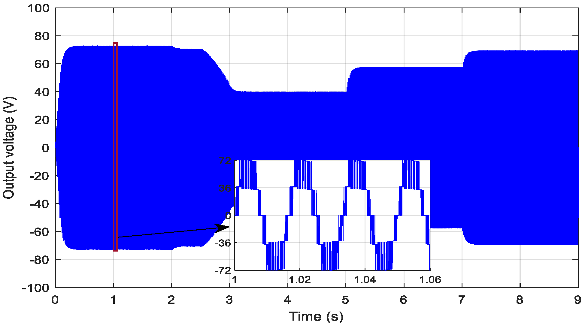
The load voltage is illustrated in
Figure 14. The voltage is comprised of five levels.
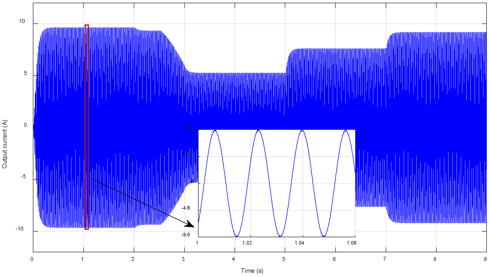
Figure 15 shows the load current; the waveform is quasi-sinusoidal and its THD is approximately 1.05%, as shown in
Figure 16, without using any filters, which ensures the efficiency of the used inverter and its controller.
4.2. Comparative Study
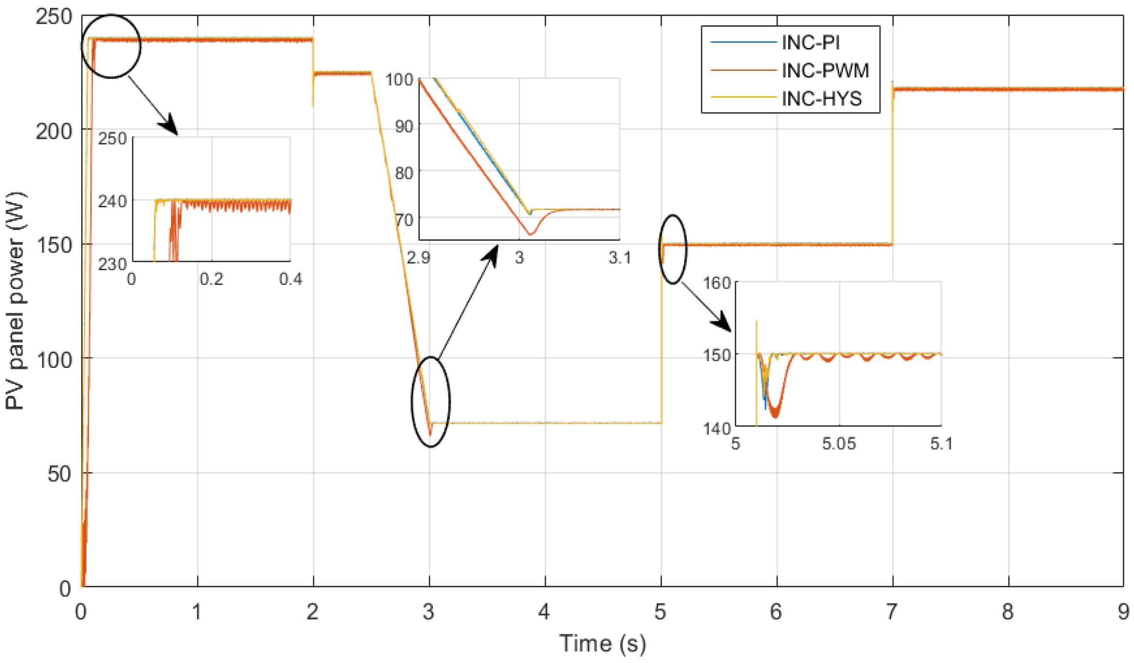
A comparative study was conducted with the INC-PWM and INC-PI algorithms to better verify the performance of the proposed MPPT algorithm (INC-HYS).
Figure 17 shows the output power of the PV panel for the three commonly used methods. As can be seen, the proposed method is faster than the INC-PI and INC-PWM to detect the MPP even after any irradiation or temperature changes. In addition, the INC-HYS technique is more accurate and has fewer oscillations compared to other methods as it is easy to implement. As a result, the proposed INC-HYS method to control the PV panel power ensures quicker and more efficient responses.
5. Conclusions
Simulations and comparison results have shown that the proposed combination of the Incremental Conductance and the Hysteresis provides high performance and good efficiency in terms of MPP tracking under static and dynamic weather conditions. The INC control is used to detect the MPP, whereas the Hysteresis control is proposed to minimize the oscillations around the MPP and improve the speed of detecting it. A boost DC/DC converter is also used to regulate and amplify the PV panel voltage.
The use of the new topology SPUC5 inverter, with PWM control technique to regulate the capacitor voltages, ensures a high signal quality to the load. The output voltage is composed of five levels and the current has a quasi-sinusoidal waveform with a 1.05% of THD without the need for any filters.
Thus, the proposed standalone PV system has provided good efficiency of all its components, from the panel to the load, whatever the external conditions.
Author Contributions
Conceptualization, H.E.O.; methodology, H.E.O. and M.M.; software, H.E.O.; validation, H.E.O. and Y.O.; formal analysis, H.E.O., M.M. and A.E.G.; writing—original draft preparation, H.E.O.; writing—review and editing, M.M. and Y.O.; visualization, H.E.O. and Y.O.; supervision, Y.O., K.A.-H. and L.B. All authors have read and agreed to the published version of the manuscript.
Funding
This research was funded by l’école de technology supérieure (ETS), Montréal, Quebec, Canada.
Conflicts of Interest
The authors declare no conflict of interest.
References
- Żywiołek, J.; Rosak-Szyrocka, J.; Khan, M.A.; Sharif, A. Trust in Renewable Energy as Part of Energy-Saving Knowledge. Energies 2022, 15, 1566. [Google Scholar] [CrossRef]
- Shoeibi, S.; Kargarsharifabad, H.; Sadi, M.; Arabkoohsar, A.; Mirjalily, S.A.A. A review on using thermoelectric cooling, heating, and electricity generators in solar energy applications. Sustain. Energy Technol. Assess. 2022, 52, 102105. [Google Scholar] [CrossRef]
- Barone, G.; Buonomano, A.; Palmieri, V.; Palombo, A. A prototypal high-vacuum integrated collector storage solar water heater: Experimentation, design, and optimization through a new in-house 3D dynamic simulation model. Energy 2022, 238, 122065. [Google Scholar] [CrossRef]
- Abid, H.; Thakur, J.; Khatiwada, D.; Bauner, D. Energy storage integration with solar PV for increased electricity access: A case study of Burkina Faso. Energy 2021, 230, 120656. [Google Scholar] [CrossRef]
- Verma, R.; Chauhan, A.; Kalia, R.; Jasrotia, R.; Sharma, M.; Kumar, R. A comprehensive study on piezo-phototronic effect for increasing efficiency of solar cells: A review. Opt. Laser Technol. 2022, 149, 107779. [Google Scholar] [CrossRef]
- Khalf, D.; Hassan, K.; Shary, D. A PV generation system based on P&O MPPT algorithm and SVPWM inverter for standalone applications. In Proceedings of the 2nd International Multi-Disciplinary Conference Theme: Integrated Sciences and Technologies, IMDC-IST 2021, Sakarya, Turkey, 7–9 September 2021. [Google Scholar]
- Rajamand, S. A novel sliding mode control and modified PSO-modified P&O algorithms for peak power control of PV. ISA Trans. 2022, 130, 533–552. [Google Scholar] [PubMed]
- Pathak, P.K.; Padmanaban, S.; Yadav, A.K.; Alvi, P.A.; Khan, B. Modified incremental conductance MPPT algorithm for SPV-based grid-tied and stand-alone systems. IET Gener. Transm. Distrib. 2022, 16, 776–791. [Google Scholar] [CrossRef]
- Mishra, J.; Das, S.; Kumar, D.; Pattnaik, M. A novel auto-tuned adaptive frequency and adaptive step-size incremental conductance MPPT algorithm for photovoltaic system. Int. Trans. Electr. Energy Syst. 2021, 31, e12813. [Google Scholar] [CrossRef]
- Nasser, K.W.; Yaqoob, S.J.; Hassoun, Z.A. Improved dynamic performance of photovoltaic panel using fuzzy logic-MPPT algorithm. Indones. J. Electr. Eng. Comput. Sci. 2021, 21, 617–624. [Google Scholar] [CrossRef]
- Jayakumar, V.; Chokkalingam, B.; Munda, J.L. A Comprehensive Review on Space Vector Modulation Techniques for Neutral Point Clamped Multi-Level Inverters. IEEE Access 2021, 9, 112104–112144. [Google Scholar] [CrossRef]
- Beniwal, N.; Tafti, H.D.; Farivar, G.G.; Ceballos, S.; Pou, J.; Blaabjerg, F. A control strategy for dual-input neutral-point-clamped inverter-based grid-connected photovoltaic system. IEEE Trans. Power Electron. 2021, 36, 9743–9757. [Google Scholar] [CrossRef]
- Sreejyothi, K.R.; Chenchireddy, K.; Lavanya, N.; Reddy, R.M.; Prasad, K.G.; Revanth, R. Level-Shifted PWM Techniques Applied to Flying Capacitor Multilevel Inverter. In Proceedings of the 2022 International Conference on Electronics and Renewable Systems (ICEARS), Tuticorin, India, 16–18 March 2022. [Google Scholar]
- Hamida, M.L.; Fekik, A.; Denoun, H.; Ardjal, A.; Bokhtache, A.A. Flying Capacitor Inverter Integration in a Renewable Energy System. In Modeling and Control of Static Converters for Hybrid Storage Systems; IGI Global: Hershey, PA, USA, 2022; pp. 287–306. [Google Scholar]
- Jayaprakash, S.; Balamurugan, R.; Gopinath, S.; Kokilavani, T.; Maheswaran, S. 3-Phase multi-inverter with cascaded H-bridge inverter designing and implementation for renewable system. Sustain. Energy Technol. Assess. 2022, 52, 102088. [Google Scholar] [CrossRef]
- Abari, I.; Hamouda, M.; Sleiman, M.; Slama, J.B.H.; Kanaan, H.Y.; Al-Haddad, K. Open-Circuit Fault Detection and Isolation Method for Five-Level PUC Inverter Based on the Wavelet Packet Transform of the Radiated Magnetic Field. IEEE Trans. Instrum. Meas. 2022, 71, 1–11. [Google Scholar] [CrossRef]
- Babaie, M.; Sharifzadeh, M.; Al-Haddad, K. Adaptive ANN based single PI controller for nine-level PUC inverter. In Proceedings of the 2019 IEEE Electrical Power and Energy Conference (EPEC), Montreal, QC, Canada, 16–18 October 2019. [Google Scholar]
- Vahedi, H.; Sharifzadeh, M.; Al-Haddad, K. Modified seven-level pack U-cell inverter for photovoltaic applications. IEEE J. Emerg. Sel. Top. Power Electron. 2018, 6, 1508–1516. [Google Scholar] [CrossRef]
- El Gadari, A.; El Ouardi, H.; Alibou, S.; Ounejjar, Y.; Bejjit, L.; Sharifzadeh, M.; Al-Haddad, K. New nine-level SPUC inverter using single DC source. In Proceedings of the IECON 2019—45th Annual Conference of the IEEE Industrial Electronics Society, Lisbon, Portugal, 14–17 October 2019; Volume 1. [Google Scholar]
- El Ouardi, H.; El Gadari, A.; Ounejjar, Y.; Kamal, A.H.; Alibou, S. A standalone photovoltaic system based on the SPUC5 inverter. In Proceedings of the 2020 IEEE 29th International Symposium on Industrial Electronics (ISIE), Delft, The Netherlands, 17–19 June 2020. [Google Scholar]
- El Ouardi, H.; El Gadari, A.; Ounejjar, Y.; Al-Haddad, K. Conception and experimental validation of a standalone photovoltaic system using the SUPC5 multilevel inverter. Electronics 2022, 11, 2779. [Google Scholar] [CrossRef]
- El Ouardi, H.; Alaoui ME, K.; Nabaoui, M.; Habib, M.; El Gadari, A.; Ounejjar, Y.; Kamal, A.H. Grid connected photovoltaic system based on SPUC5 inverter. In Proceedings of the 2021 22nd IEEE International Conference on Industrial Technology (ICIT), Valencia, Spain, 10–12 March 2021; Volume 1. [Google Scholar]
- El Ouardi, H.; El Gadari, A.; Ounejjar, Y.; Al-Haddad, K.; Alibou, S. Grid connected Photovoltaic System Based on SPUC9 Inverter. In Proceedings of the 2020 5th International Conference on Renewable Energies for Developing Countries (REDEC), Marrakech, Morocco, 29–30 June 2020. [Google Scholar]
- Siddique MA, B.; Khan, M.A.; Asad, A.; Rehman, A.U.; Asif, R.M.; Rehman, S.U. Maximum power point tracking with modified incremental conductance technique in grid-connected PV array. In Proceedings of the 2020 5th International Conference on Innovative Technologies in Intelligent Systems and Industrial Applications (CITISIA), Sydney, Australia, 25–27 November 2020; pp. 1–6. [Google Scholar]
- Abou Jieb, Y.; Hossain, E.; Hossain, E. Solar Cell Properties and Design. In Photovoltaic Systems; Springer: Cham, Switzerland, 2022; pp. 57–71. [Google Scholar]
- Ahmed, H.Y.; Abdel-Rahim, O.; Ali, Z.M. New High-Gain Transformerless DC/DC Boost Converter System. Electronics 2022, 11, 734. [Google Scholar] [CrossRef]
| Disclaimer/Publisher’s Note: The statements, opinions and data contained in all publications are solely those of the individual author(s) and contributor(s) and not of MDPI and/or the editor(s). MDPI and/or the editor(s) disclaim responsibility for any injury to people or property resulting from any ideas, methods, instructions or products referred to in the content. |
© 2023 by the authors. Licensee MDPI, Basel, Switzerland. This article is an open access article distributed under the terms and conditions of the Creative Commons Attribution (CC BY) license (https://creativecommons.org/licenses/by/4.0/).

 ,
, 


