
Thermal Insulation of Hybrid GFRP-Lightweight Concrete Structures

Civil Engineering Research and Innovation for Sustainability (CERIS), IST-ID—Associação do Instituto Superior Técnico para a Investigação e Desenvolvimento, Av. Rovisco Pais, 1049-001 Lisbon, Portugal
*
Author to whom correspondence should be addressed.
CivilEng 2023, 4(2), 584-595; https://doi.org/10.3390/civileng4020034
Submission received: 10 March 2023
/
Revised: 1 May 2023
/
Accepted: 22 May 2023
/
Published: 25 May 2023
(This article belongs to the Special Issue Feature Papers in CivilEng)
Abstract
:This paper presents a numerical study on the thermal effect of the insulation of lightweight concrete in hybrid GFRP-concrete structures. In these hybrid structures, the GFRP profiles are totally covered by normal and lightweight concrete and subjected to thermal loads. The problem with GFRP structures is their weak thermal resistance, even at moderately high temperatures. To promote some thermal insulation, it is recommended to cover the GFRP profile with concrete, but this increases its weight. Therefore, lightweight concrete may be a good solution due to its insulation capabilities. For this study, the thermal loads used in the numerical campaign are based on a nominal fire-curved ISO-834, and the temperature is measured at several points. Using these temperatures, it is possible to conclude that the effect of lightweight concrete may provide structural benefits when compared with classical standard structural concrete for covering GFRP profiles using different cover values (from 5.0 cm to 2.5 cm). For this work, commercial finite element software was used for the thermal nonlinear analysis. It was possible to conclude that with lightweight concrete, it is likely to have half of the cover and still maintain the same level of insulation as regular concrete.
1. Introduction
The recent use of FRP structures is growing in the civil engineering industries [1], and its application in the scientific community is highly regarded, with a new Eurocode for FRP structures on the horizon [2]. It allowed for future predesign guidelines to be applied to FRP structures in real-life load scenarios [3].
FRP materials (FRPs) have enormous potential as construction materials, presenting several advantages when compared with traditional materials: high mechanical performance, lightness, low maintenance, improved durability, and increasingly competitive costs [4,5]. These characteristics are particularly relevant for building rehabilitation or pedestrian bridges [6,7], since the use of FRPs often does not need elevation devices and introduces much lower loads over existing construction elements.
With regard to its lightness, this material is economically competitive for the construction of temporary structures in emergency situations and in the rehabilitation of old structures [8]. The lightness and ease of assembly are important additional advantages, reducing the costs and duration of the work, which is also vital in new construction [9].
Recently, with the study of new orthotropic damage models applied to glass fiber reinforced polymer (GFRP) structures [10,11], it has been possible to fully understand their postpeak behaviour in real column-beam connections in GFRP structures [12].
The use of FRPs with RC offers several advantages (despite their higher initial costs), relative to their increased strength and anticorrosion properties [13,14,15]. However, several concerns exist relative to the fire behaviour performance of GFRPs due to their mechanical and adhesion properties being drastically reduced after (70–150 °C), which is why the main design codes/guidelines discourage the use of FRP in building structures until a consistent fire insulation is achieved.
For this reason, the use of hybrid GFRP-concrete structure requires a thick cover to consider the need of fire insulation with concrete. However, thick cover is a noneconomic solution, and increases the total weight, just to gain fire resistance. A solution is to use lightweight concrete (LC) instead of normal concrete (NC), due to its higher insulation properties for ambient and high temperatures. In addition, contrary to steel reinforced LC, in hybrid GFRP-LC structures there is no fasten corrosion problem in the long term, which is a known disadvantage in the scientific community when using LC with steel (contrary to NC). Furthermore, the use of normal concrete takes advantage of the lightness of GFRP, which makes the use of lightweight concrete an attractive alternative. This last statement is even more important, especially in zones prone to earthquakes, in which this hybrid GFRP-LC presents less self-weight, and therefore, fewer structural responses to seismic activity.
1.1. Objectives
The main objective of this work is to study the thermal insulation efficiency of the use of LC in hybrid GFRP-concrete structures. This is performed using a thermal numerical analysis with the aid of the commercial finite element software ABAQUS. A numerical non-linear thermal analysis is performed in a 2D hybrid GFRP-concrete section with normal and lightweight concrete, in which all the thermal properties are temperature-dependent. To assess the efficiency of the insulation, internal temperatures are compared at different heights, with different covers and different types of concretes.
1.2. Research Significance
According to the authors’ best knowledge, research regarding the thermal performance of hybrid GFRP-LC beams when subjected to a nominal ISO-834 interior fire [16] is almost null in the scientific community. Although it is known in the scientific community that LC presents lower conductivity than NC, there is no reference in Eurocode 2: Design of concrete structures—Part 1–2: General rules—Structural fire design regarding the minimum needed cover for LC to present the same insulation as NC. This study plans to fill this gap in knowledge.
2. Applications of Hybrid GFRP Concrete Structures
2.1. The Known Fire Problem in GFRP Structures
The application of FRP materials has been focused on bridges since fire resistance is not a design requisite. Its application in buildings has been postponed due to its performance in the presence of fire [17], in which its mechanical and resistance properties are severely reduced at 70–150 °C, values close to the glass transition temperature (Tg) [18]. Moreover, even at temperatures lower than standard building fires 350–500 °C, their organic matrix decomposes, causing further deterioration [19].
Fire resistance tests on RC beams strengthened with conventional FRP bonded with epoxy-based adhesives [20] have confirmed the reductions in mechanical and bond properties at elevated temperatures. Recent research conducted at the research centre CERIS [21] has shown that large thicknesses of thermal insulation are generally only needed in the FRPs’ anchorage zones.
In terms of GFRP rebars, some authors [22] have reported that when the Tg is exceeded, a loss of bond between the GFRP and concrete occurs. This leads to premature structural collapse due to bar debonding in lap-splices [23]. Therefore, the use of normal RC takes advantage of the lightness of GFRP, which makes the use of lightweight concrete (LC) an attractive alternative.
During the last 10 years, investigations in CERIS research centre have developed extensive know-how on the fire performance and behaviour of civil engineering materials and concrete structures [24,25]. In these works, it was concluded that FRP, and more precisely, GFRP structures, can indeed compute with classical steel reinforced concrete structures for ambient temperatures. However, for higher temperatures, due to low glass temperature transition in GFRP, the structural robustness is dependent on an efficient thermal insulation. Therefore, extra studies were promoted; these included: extensive experimental and numerical campaigns in bond at elevated temperatures of FRP-RC beams [26,27]; fire behaviour of GFRP profiles [28]; strengthened FRP-RC beams [21]; and lately, fire behaviour of GFRP rebars in RC beams [29].
2.2. Motivation for the Use of Lightweight Concrete
Recent studies [30,31] indicate that it is possible to take advantage of a simple GFRP-RC connection with a significant increase in resistance. Therefore, by using LC, which has only 1/4 of the conductibility of RC, it is expected to fully cover a GFRP profile with a minimum covering while maintaining some lightness in order to have an increase in resistance to ambient temperature and improved fire behaviour.
Another advantage of using a combination of GFRP and LC is that steel rebars tend to initiate corrosion more quickly due to the high level of carbonation in LC when compared with normal RC. In this case, the carbonation does not affect the GFRP since no corrosion exists.
Finally, a hybrid GFRP-LC design is feasible, confirming the building’s fire safety code. This research, like earlier fire research (1970s) in composite steel-concrete structures, in which the concrete protected the steel from high temperatures, aims to fill this gap in knowledge.
2.3. Recent Developments in Hybrid GFRP Concrete Structures
Although some research exists concerning hybrid GFRP-RC beams [30,32,33], due to the idea that the interface behaviour of GFRP-RC is almost nonexistent, this research path has been forgotten. Recently, several authors have confirmed through experimental results [30,31,34] that this may not be true, and that further investigations are necessary in order to achieve the correct bond-slip in GFRP-RC. Moreover, some authors have encouraged results regarding hybrid GFRP-RC beams if proper connections or adhesives are used [35]. In the last work of Ines Rosa [29], GFRP rebars without ribs were proven to have an efficient adhesion/connection to normal concrete, confirming that the interface between GFRP-RC is not negligible.
3. Thermal Properties
For the thermal properties and their temperature variation, it was chosen to use values and variations from known structural Eurocodes for concrete and GFRP structures. Therefore, the volumetric mass density, conductivity, and specific heat for concrete are obtained from Eurocode 2: Design of concrete structures—Part 1–2: General rules—Structural fire design [36] for elevated temperatures (1). For the flux boundary prescribed parameters concerning convection and radiation, the values proposed in [37] were adopted. A summary of all thermal material properties at ambient temperature is in Table 1.
3.1. Concrete
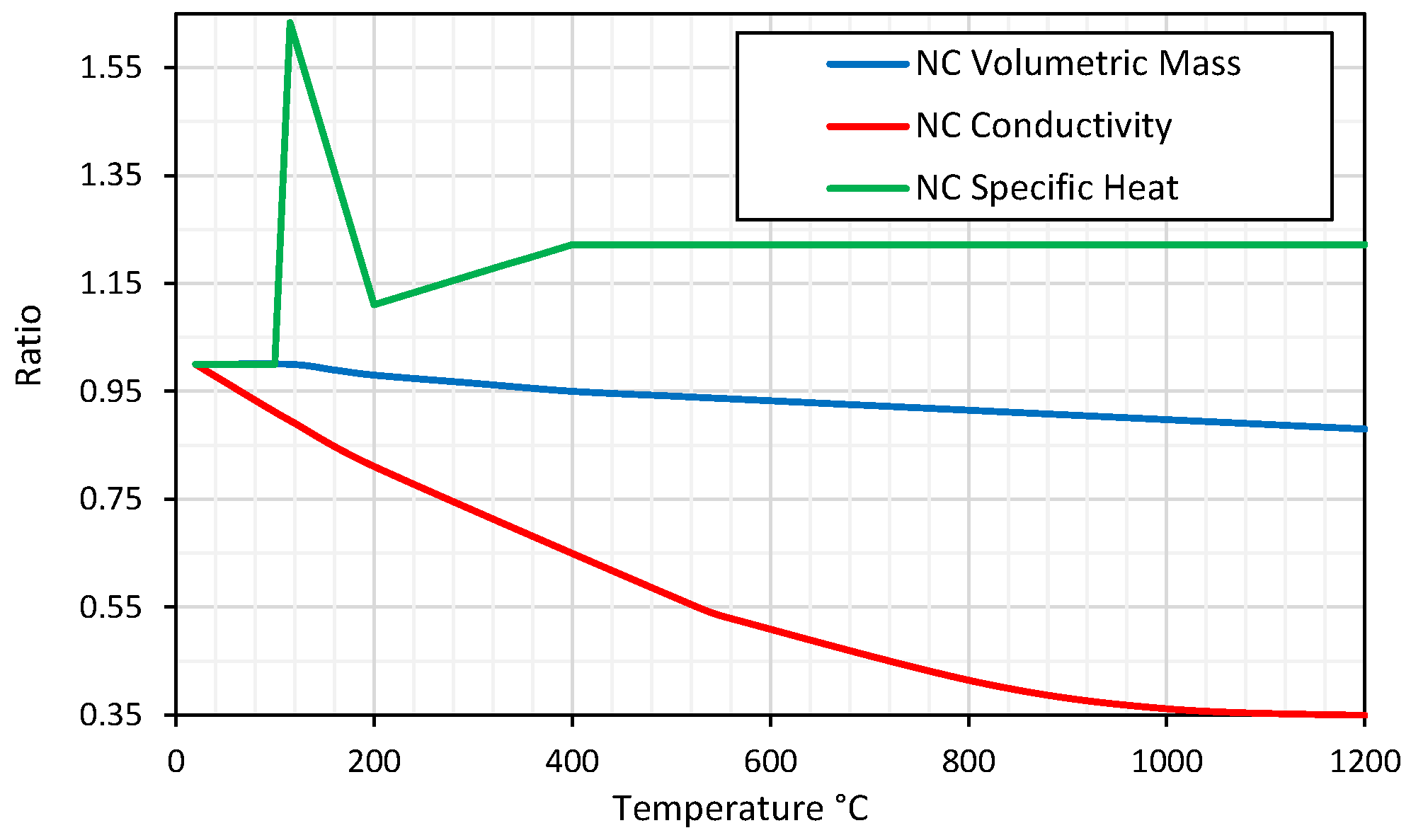
For the normal concrete, the thermal property values for an ambient temperature of 20 °C were used, which include volumetric mass , conductivity and specific heat . Its ratio variations (1) with temperature are depicted in Figure 1, and are according to [36] for elevated temperatures.
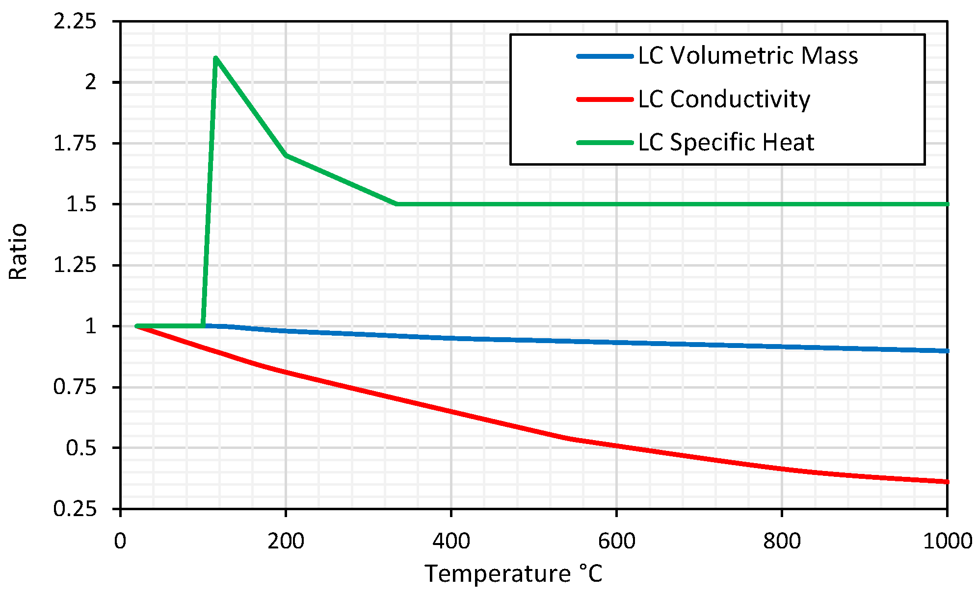
For LC, the values of thermal properties at ambient temperature are, according to recent studies [38], , conductivity and specific heat . For the LC, the ratio variation for high temperatures was the same as normal concrete for volumetric mass and conductivity Figure 2. However, for the specific heat, the ratio variation from the work of [39] was used, since the one adopted from NC is not applicable, according to these authors.
3.2. GFRP
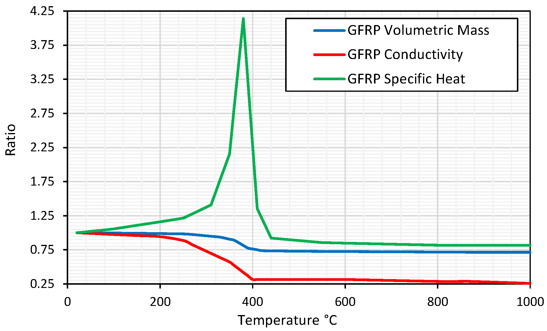
Thermal property data for an ambient temperature of 20 °C were used for the GFRP [2,40], concerning volumetric mass , conductivity , and specific heat . Although, as referred to in Table 1 that GFRP does not possess a reliable structural performance for temperatures above 200 °C, in any case, it was admitted that it had thermal properties above this value for the thermal heat transfer analysis. In Figure 3, the ratio variations (1) of the thermal properties are presented for the GFRP, and these are according to the results from the work of [40].
3.3. Convection and Radiation
According to [37], when using nominal fire curves such as ISO-834, it is recommended to use a convection coefficient of , a Stefan–Boltzmann constant of , and an emissivity of 0.7 for the radiation flux for all materials, as recommended for concrete in Eurocode 2: Design of concrete structures—Part 1–2: General rules—Structural fire design [36]. Different values can be adopted, but these were chosen for this numerical study since they are related to the thermal parameters used for ultimate limit state verification.
4. Numerical Model
In this section, the numerical model used to assess the efficiency of the concrete thermal cover is fully described. It presents the geometry and mesh only for the 5.0 cm. For the 2.5 cm cover, half of the cover is suppressed, but the proceedings are similar. For the finite element analysis, the commercial software ABAQUS standard is used, with a nonlinear thermal analysis, in which all the material properties are temperature-dependent.
4.1. Geometry and Boundaries
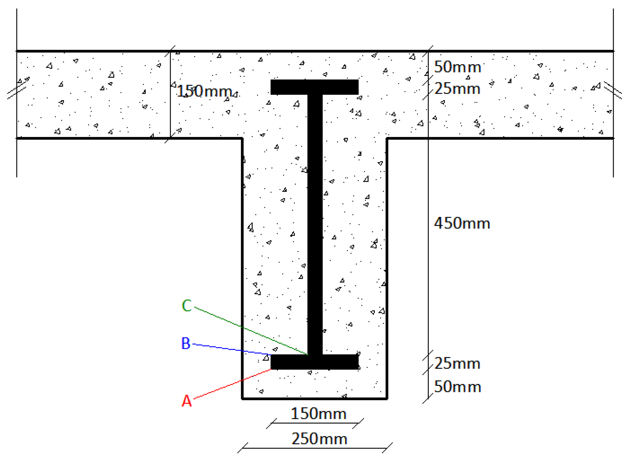
A standard section involving a beam and concrete slab was used to simulate real structural geometry, for a 5 m span in a residential building. For this reason, a beam with dimensions 600 mm × 250 mm was used (Figure 4), connected to a slab of 150 mm thickness. For the GFRP a classical I profile is used with a total height of 500 mm, therefore a cover of 50 mm was adopted. It is important to note that for steel rebars, the cover is around 30 mm to 40 mm; in any case, more thick cover was chosen to provide some insulation for the GFRP profile, when the bottom surface to the beam is subjected to a fire.
The slab has a total width of 600 mm, and its left and right boundaries are considered thermally adiabatic. For a classical concrete slab, supported by beams, a thickness of 150 mm is standard for spans from 3.0 m to 4.0 m. To reduce the computational cost, symmetry theory was applied in the vertical axis, and in this boundary, the thermal adiabatic condition is also attributed.
4.2. Type of Analysis
A 2D thermal nonlinear analysis, with Newton-Raphson predictor corrector, is used, and necessary, due to the thermal properties of the materials being temperature-dependent. Nonlinear heat transfer difficulties can occur when the material properties are temperature-dependent or when the boundary conditions are nonlinear. Temperature-dependent material properties often have minor nonlinearity since the properties do not change quickly with temperature. To address nonlinear heat transfer issues, Abaqus/Standard employs an iterative approach. The approach employs the Newton-Raphson method, with some modifications, to increase the iteration process’s stability in the presence of highly nonlinear latent heat effects. To control the flux transfer between nodes, the maximum allowed temperature change per increment was 20K. This is necessary according to [41], in which the time step increment will decrease, but will produce a more stable numerical nonlinear thermal solution.
4.3. Thermal Loads
Different thermal loads were applied to the bottom and latter surfaces of the beam cross-section, which is according to the design requirements of Eurocode 2: Design of concrete structures—Part 1–2: General rules—Structural fire design. For the bottom and lateral surfaces of the beam and slab, a prescribed boundary flux with convection and radiation was applied (2). For the bottom and lateral surfaces of the beam and slab (Figure 5b,c), the sink temperature is equal to the ISO-834 [16] fire nominal curve (3). However, for the top surface of the slab and beam, ambient constant temperature was adopted for the sink temperature . Nonlinear boundary conditions are common but modest and provide minimal difficulties. Heat transfer problems are always nonlinear due to radiation effects, and as temperatures rise, nonlinearities in radiation increase.
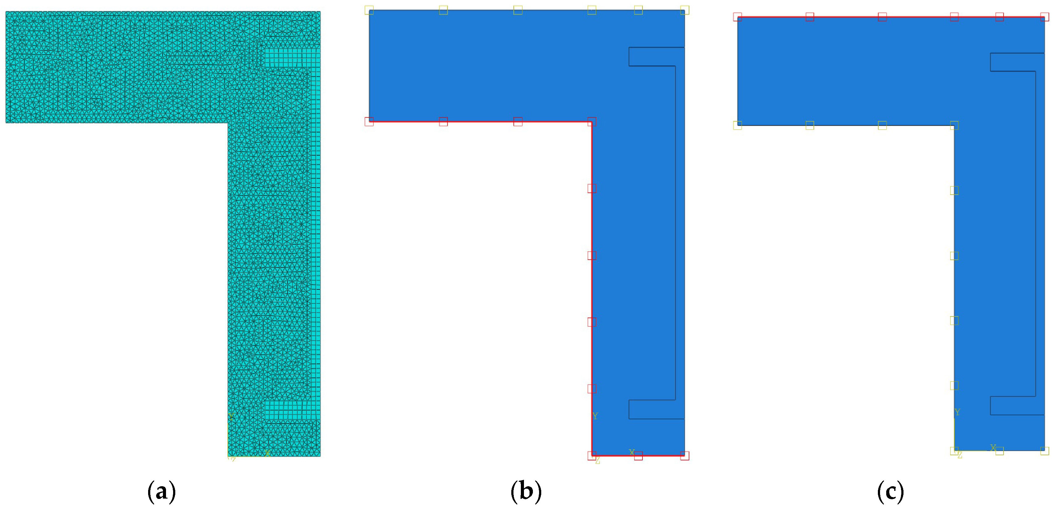
4.4. Adopted Mesh
For the adopted mesh, two different types of elements were used for the GFRP and concrete. For the GFRP, a structured mesh using eight-quad node element DC2D8 with full integration was used, but for the concrete, a triangular six-node element DC2D6 with full integration was adopted, using an advancing front mesh. Different elements were used in the concrete and GFRP, due to the difficulty of presenting a correct, nondistorted mesh only with quad elements. When generating the mesh, it was admitted a maximum size of 7.0 mm for the quad elements in the GFRP, and a maximum size of 6.0 mm for the triangular elements in the concrete. These maximum sizes are more than enough due to the use of quadratic approximation functions.
5. Analysis of the Results
In this section, the results from the thermal nonlinear analysis of a hybrid GFRP-concrete 2D section with normal and LC and different concrete cover thicknesses are presented. According to [2], the average stiffness and strength of GFRP are severely reduced at high temperatures, and the reduction ratios are presented in Table 2. It is important to point out that for temperatures near 200 °C, both stiffness and strength present a severe reduction, and it can be admitted that the GFRP structural performance is compromised, and collapse is imminent. Therefore, for the analysis of the results, it will be considered that temperature values above 200 °C are unacceptable to be used as a structural solution.
The temperatures are measured at three points, which are represented in Figure 4: Point A is on the lower surface of the bottom flange of the GFRP profile; point B is on the upper surface of the bottom flange of the GFRP profile; and point C is on the bottom connection between the flange and the web. These three chosen points are related to the upper and lower temperature distribution in the flange, and the maximum temperature in the connection between the flange and the web. When all these three points reach values above 300 °C, there is no guarantee of structural safety.
For the first example, it is considered to have the same geometry as in Figure 4, with a concrete cover of 5.0 cm. However, for the second example, the cover thickness is reduced by 12 by adopting a value of 2.5 cm. In any case, the points are analogous to the initial geometry but with different heights.
5.1. Geometry with 5.0 cm of Concrete Cover
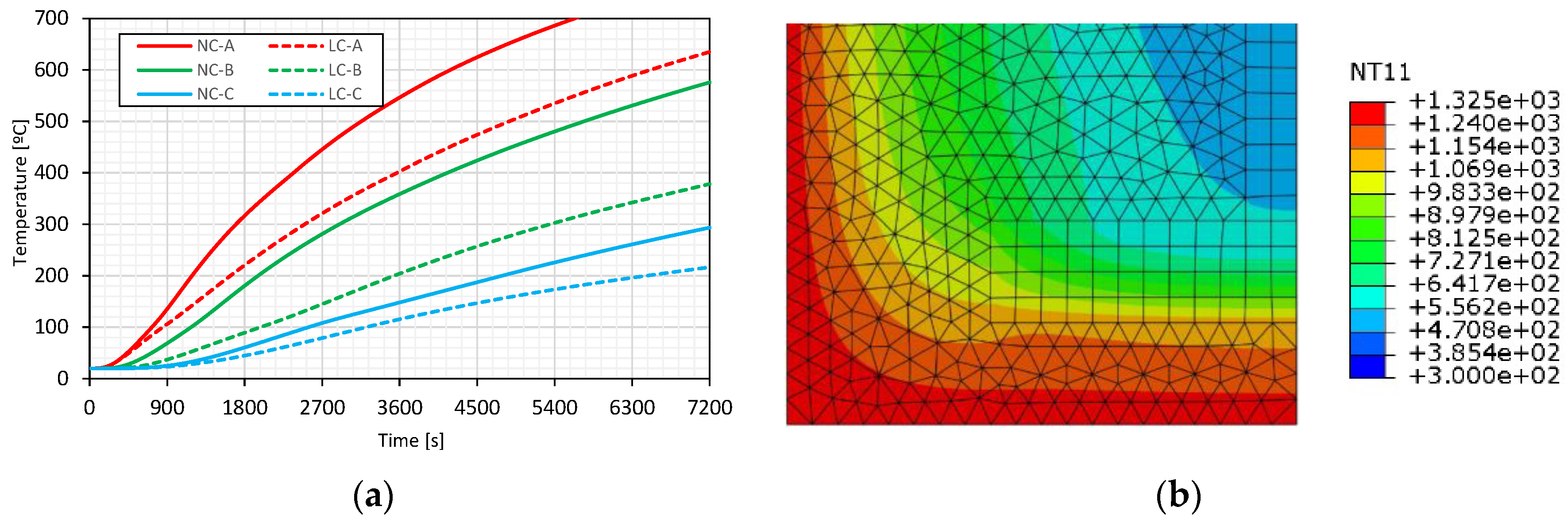
In Figure 6a, it is possible to observe that for NC, both points A and B reach values of temperature above 200 °C just after 45 min, and in particular, point A after only 25 min, not even reaching the 12 h mark. Contrary to LC, both points A and B took more than 75 min to reach the temperature of 200 °C. For point C, it took NC more than 90 min to reach temperatures above 200 °C, but this temperature value was never reached for 2 h in point C for LC. From Figure 6a, it is possible to conclude that the top surface of the bottom GFRP flange surface presents temperatures between 100 °C and 300 °C after 2 h of fire exposure with LC, compared with a range of temperatures between 300 °C and 500 °C with NC.
Although this is only a thermal analysis, it can be approximately stated that the solution with LC presented an extra thermal safety around 30 min. This is related to the temperature in the flange being lower in the LC than NC, and that the temperature in the connection between the web and the flange not passing 200 °C even after 2 h. For the bottom surface, its maximum temperature is around 1040 °C, a value close to 1049 °C reached by the ISO-834 after 2 h of fire exposure, therefore validating the numerical model, when the boundary temperatures are directly compared. Moreover, the temperature field distribution is also very similar to the one present in Annex A of Eurocode 2: Design of concrete structures—Part 1–2: General rules—Structural fire design, for two hours of fire exposure to the nominal ISO-834 curve.
5.2. Geometry with 2.5 cm of Concrete Cover
For the 2.5 cm cover, the temperature variation in time at the same points A, B, and C marked in Figure 4 are depicted in Figure 7. Although points B and C present similar temperature variations for covers of 5.0 cm and 2.5 cm, respectively, there is a clear difference in point A. For point A, the temperatures are 697 °C and 785 °C for 5.0 cm and 2.5 cm of cover, respectively. In Figure 6b) with a 5.0 cm cover, even for NC, the temperature in the GFRP web is clearly below 250 °C, but for a 2.5 cm cover in Figure 7b), this value raises almost to 300 °C. For this reason, the reduction of the NC cover cannot properly insulate the GFRP web from elevated temperatures, and the use of LC is fundamental.
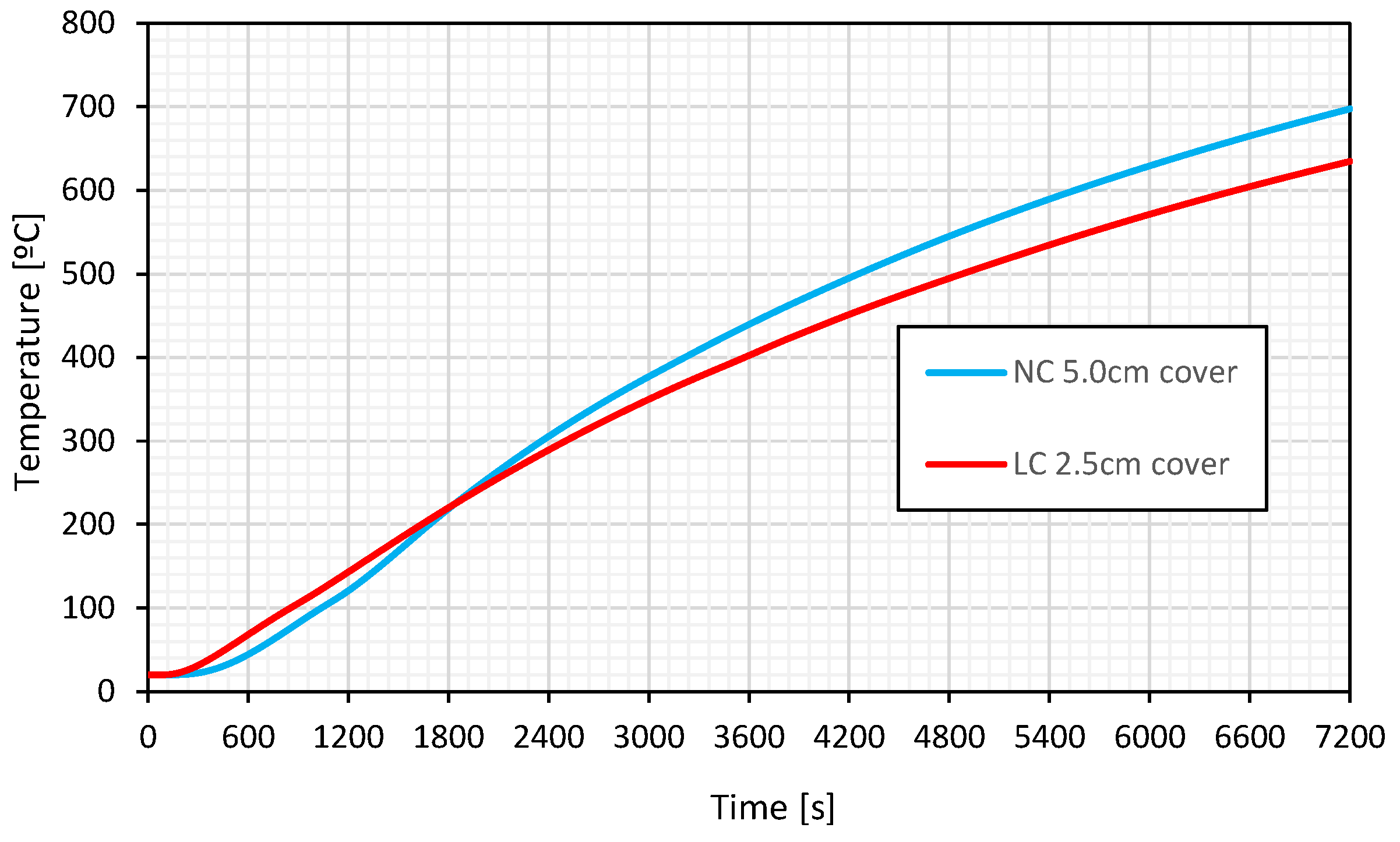
Another important fact can be observed in Figure 8 for point A, in which the NC with 5.0 cm reaches 200 °C after 30 min, but the same LC with 2.5 cm also reaches this temperature value after 30 min. This leads to the conclusion that LC with half the cover of NC may present the same fire resistance time in hybrid GFRP-concrete structures.
6. Conclusions
In this study, the efficiency of thermal isolation with LC in hybrid GFRP-concrete structures was numerically assessed, using thermal nonlinear analysis with classical finite element models, in which all thermal properties were temperature dependent. Four numerical models were assembled, with different concrete types from normal to light weight, and with different covers from 2.5 cm to 5.0 cm, in order to understand the need for a lower cover thickness with LC. Several conclusions and assumptions can be derived from this numerical campaign:
- It was concluded that for the same level of concrete cover over the GFRP, LC can achieve an extra fire resistance exposure time of around 30 min when compared with NC for hybrid GFRP-concrete structures. This condition is comparable with the ones provided by adding a small thickness of silicate of calcium (SC), normally used in fireproof solutions.
- In addition, the temperature distribution with NC and LC was compared with different concrete covers over the GFRP, and it was possible to conclude that LC needs less cover to present the same fire resistance exposure time. Since only half of the cover is needed for the LC solution, and the self-weight is smaller, the total structural dead load is smaller, reducing future structural responses due to earthquakes.
- Even for NC, the temperature in the GFRP web is clearly below 250 °C with a 5.0 cm cover, but with a 2.5 cm cover, this value rises almost to 300 °C after two hours. For LC with 2.5 cm, in the GFRP web this value is around 200 °C after two hours, which is enough to maintain some residual strength and stiffness in the GFRP.
- As a result, reducing the NC cover cannot adequately insulate the GFRP web from elevated temperatures, and the use of LC is critical to achieve an economical and efficient structure.
6.1. Limitations of the Study
This study is only comprised of a thermal analysis, in which the maximum allowed temperature in the GFRP is compared, meaning the results extrapolated for the mechanical analysis are only an approximation. Moreover, the efficiency of the interface between the GFRP and the concrete was not taken into account, and some recent studies [29,42] have suggested that the connection between GFRP and concrete is almost neglected above 150 °C. For this reason, the idea of using LC can promote a more robust solution in hybrid GFRP-concrete structures when subjected to the action of a nominal interior fire. In addition, these cover geometries are only valid for fire in the interior of the building; for external fires or wildfires, extra research may be needed.
6.2. Further Developments
To better understand the difference in the structural response of hybrid GFRP-concrete structures, when subjected to the action of a nominal fire curve with NC and LC, a sequentially coupled thermal-mechanical analysis is necessary. It is expected to embark on a future 3D numerical campaign to access the previous conclusions more correctly. The problem is that the bond-slip interface between GFRP profiles and LC is not known at the moment; therefore, the bond-slip used in GFRP rebars from the work [29] will be used. Another important aspect ot study at ambient and high temperatures in the near future is the beam-column and slab-beam of hybrid GFRP-LC structures, in which some know-how is already present in the previous work of [12].
Author Contributions
Conceptualization, M.R.T.A., P.C. and R.B.; methodology, M.R.T.A.; validation, M.R.T.A., P.C. and R.B.; formal analysis, M.R.T.A.; investigation, M.R.T.A., P.C. and R.B.; resources, P.C. and R.B.; data curation, P.C. and R.B.; writing—original draft preparation, M.R.T.A., P.C. and R.B.; writing—review and editing, P.C. and R.B.; visualization, M.R.T.A., P.C. and R.B.; supervision, M.R.T.A., P.C. and R.B.; project administration, M.R.T.A. All authors have read and agreed to the published version of the manuscript.
Funding
This project is funded by FCT, Fundação para Ciência e Tecnologia em Portugal (Research Project “New Fireproof Dwellings for WildFire” PTDC/ECI-CON/2240/2020).
Data Availability Statement
Not applicable.
Acknowledgments
The authors would like to acknowledge FCT, National Funding Agency for Science, Research and Technology, Portugal (Research Project “New Fireproof Dwellings for WildFire” PTDC/ECI-CON/2240/2020) and CERIS for the financial support. This work has been partly supported by Fundação para a Ciência e Tecnologia (FCT), under the Transitional Standard—DL57/2016/N3/UI/CERIS/CT/165/2018.
Conflicts of Interest
The authors declare no conflict of interest.
References
- FIB. Fib Bulletin No. 40—FRP Reinforcement in RC Structures; FIB: Lausanne, Switzerland, 2007. [Google Scholar]
- CEN/TC250; Introductory Element—Design of Fibre Reinforced Polymer Structures—Complementary Element. CEN/TC250 Working Group (WG) 4: Brussels, Belgium, 2020.
- Arruda, M.R.T.; Lopes, B. Pre-design guidelines for GFRP composite sandwich panels. Eng. Solid Mech. 2020, 8, 169–186. [Google Scholar] [CrossRef]
- Bakis, C.E.; Bank, L.C.; Brown, V.L.; Cosenza, E.; Davalos, J.F.; Lesko, J.J.; Machida, A.; Rizkalla, S.H.; Triantafillou, T.H. Fibre Reinforced Polymer Composites for Construction—State-of-the-Art Review. J. Compos. Constr. 2002, 6, 73–87. [Google Scholar] [CrossRef]
- Correia, J.R.; Cabral-Fonseca, S.; Branco, F.A.; Ferreira, J.G.; Eusébio, M.I.; Rodrigues, M.P. Durability of pultruded glass-fiber-reinforced polyester profiles for structural applications. Mech. Compos. Mater. 2006, 42, 325–338. [Google Scholar] [CrossRef]
- Correia, J.R.; Branco, F.A.; Ferreira, J. GFRP–concrete hybrid cross-sections for floors of buildings. Eng. Struct. 2009, 31, 1331–1343. [Google Scholar] [CrossRef]
- Correia, J.R.; Branco, F.A.; Ferreira, J.G. Flexural behaviour of GFRP–concrete hybrid beams with interconnection slip. Compos. Struct. 2007, 77, 66–78. [Google Scholar] [CrossRef]
- Ramôa Correia, J. 9—Pultrusion of advanced fibre-reinforced polymer (FRP) composites A2—Bai, Jiping. In Advanced Fibre-Reinforced Polymer (FRP) Composites for Structural Applications; Woodhead Publishing: Sawston, UK, 2013. [Google Scholar]
- Correia, J.R. Glass Fibre Reinforced Polymer (GFRP) Pultruded Profiles. Use of GFRP-Concrete Hybrid Beams in Construction. Master’s Thesis, Instituto Superior Técnico, Lisboa, Portugal, 2004. [Google Scholar]
- Arruda, M.R.T.; Almeida-Fernandes, L.; Castro, L.; Correia, J.R. Tsai–Wu based orthotropic damage model. Compos. Part C Open Access 2021, 4, 100122. [Google Scholar] [CrossRef]
- Arruda, M.R.T.; Trombini, M.; Pagani, A. Implicit to Explicit Algorithm for ABAQUS Standard User-Subroutine UMAT for a 3D Hashin-Based Orthotropic Damage Model. Appl. Sci. 2023, 13, 1155. [Google Scholar] [CrossRef]
- Martins, D.; Proença, M.; Correia, J.R.; Gonilha, J.; Arruda, M.; Silvestre, N. Development of a novel beam-to-column connection system for pultruded GFRP tubular profiles. Compos. Struct. 2017, 171, 263–276. [Google Scholar] [CrossRef]
- Garnevičius, M.; Gribniak, V. Developing a hybrid FRP-concrete composite beam. Sci. Rep. 2022, 12, 16237. [Google Scholar] [CrossRef]
- Shoeib, A.E.-K.; Arafa, A.N.; Sedawy, A.E.-S.; EL-Hashmy, A.M. The shear strength of concrete beams hybrid-reinforced with GFRP bars and steel bars in main reinforcement without shear reinforcement. Curved Layer. Struct. 2022, 9, 146–162. [Google Scholar] [CrossRef]
- Zhao, J.; Pan, H.; Wang, Z.; Li, G. Experimental and Theoretical Study on Flexural Behavior of GFRP- and CFRP-Reinforced Concrete Beams after High-Temperature Exposure. Polymers 2022, 14, 4002. [Google Scholar] [CrossRef]
- ISO-834-1; Fire-Resistance Tests—Elements of Building Construction—Part 1: General Requirements. International Organization for Standardization: Geneve, Switzerland, 1999.
- Karbhari, V.M.; Chin, J.W.; Hunston, D.; Benmokrane, B.; Juska, T.; Morgan, R.; Lesko, J.J.; Sorathia, U.; Reynaud, D. Durability Gap Analysis for Fiber-Reinforced Polymer Composites in Civil Infrastructure. J. Compos. Constr. 2003, 7, 238–247. [Google Scholar] [CrossRef]
- Dodds, N.; Gibson, A.G.; Dewhurst, D.; Davies, J.M. Fire behaviour of composite laminates. Compos. Part A Appl. Sci. Manuf. 2000, 31, 689–702. [Google Scholar] [CrossRef]
- Mouritz, A.P.; Mathys, Z.; Gibson, A.G. Heat release of polymer composites in fire. Compos. Part A Appl. Sci. Manuf. 2006, 37, 1040–1054. [Google Scholar] [CrossRef]
- Williams, B.; Bisby, L.; Kodur, V.; Green, M.; Chowdhury, E. Fire insulation schemes for FRP-strengthened concrete slabs. Compos. Part A Appl. Sci. Manuf. 2006, 37, 1151–1160. [Google Scholar] [CrossRef]
- Firmo, J.P.; Arruda, M.R.T.; Correia, J.R.; Tiago, C. Flexural behaviour of partially bonded carbon fibre reinforced polymers strengthened concrete beams: Application to fire protection systems design. Mater. Des. 2015, 65, 1064–1074. [Google Scholar] [CrossRef]
- Webber, A. Fire-resistance tests on composites rebars. In Proceedings of the Fourth International Conference on FRP Composites in Civil Engineering (CICE2008), Zurich, Switzerland, 22–24 July 2008. [Google Scholar]
- Nigro, E.; Cefarelli, G.; Bilotta, A.; Manfredi, G.; Cosenza, E. Fire resistance of concrete slabs reinforced with FRP bars. Part I: Experimental investigations on the mechanical behavior. Compos. Part B Eng. 2011, 42, 1739–1750. [Google Scholar] [CrossRef]
- Marques, A.M.; Correia, J.R.; de Brito, J. Post-fire residual mechanical properties of concrete made with recycled rubber aggregate. Fire Saf. J. 2013, 58, 49–57. [Google Scholar] [CrossRef]
- Santos, J.; Brito, J.; Branco, F.A. Assessment of Concrete Structures Subjected to Fire—The FBTest. Mag. Concr. Res. 2002, 54, 203–208. [Google Scholar] [CrossRef]
- Arruda, M.R.T.; Firmo, J.P.; Correia, J.R.; Tiago, C. Numerical modelling of the bond between concrete and CFRP laminates at elevated temperatures. Eng. Struct. 2016, 110, 233–243. [Google Scholar] [CrossRef]
- Firmo, J.P.; Pitta, D.; Correia, J.R.; Tiago, C.; Arruda, M.R.T. Experimental characterization of the bond between externally bonded reinforcement (EBR) CFRP strips and concrete at elevated temperatures. Cem. Concr. Compos. 2014, 60, 44–54. [Google Scholar] [CrossRef]
- Correia, J.R.; Gomes, M.M.; Pires, J.M.; Branco, F.A. Mechanical behaviour of pultruded glass fibre reinforced polymer composites at elevated temperature: Experiments and model assessment. Compos. Struct. 2013, 98, 303–313. [Google Scholar] [CrossRef]
- Rosa, I.C.; Firmo, J.P.; Correia, J.R.; Barros, J.A.O. Bond behaviour of sand coated GFRP bars to concrete at elevated temperature—Definition of bond vs. slip relations. Compos. Part B Eng. 2019, 160, 329–340. [Google Scholar] [CrossRef]
- Aydın, F.; Sarıbıyık, M. Investigation of flexural behaviors of hybrid beams formed with GFRP box section and concrete. Constr. Build. Mater. 2013, 41, 563–569. [Google Scholar] [CrossRef]
- Aydın, F.; Sarıbıyık, M. Compressive and Flexural Behavior of Hybrid Use of GFRP Profile with Concrete; Sakarya University: Sakarya, Turkey, 2016. [Google Scholar]
- Correia, J.R.; Branco, F.A.; Ferreira, J.G. Flexural behaviour of multi-span GFRP-concrete hybrid beams. Eng. Struct. 2009, 31, 1369–1381. [Google Scholar] [CrossRef]
- Gonilha, J.A.; Correia, J.R.; Branco, F.A. Dynamic response under pedestrian load of a GFRP–SFRSCC hybrid footbridge prototype: Experimental tests and numerical simulation. Compos. Struct. 2013, 95, 453–463. [Google Scholar] [CrossRef]
- Ribeiro, M.C.S.; Tavares, C.M.L.; Ferreira, A.J.M.; Marques, A.T. Static Flexural Performance of GFRP-Polymer Concrete Hybrid Beams. Key Eng. Mater. 2002, 230–232, 148–151. [Google Scholar] [CrossRef]
- Zou, X.; Feng, P.; Wang, J. Perforated FRP ribs for shear connecting of FRP-concrete hybrid beams/decks. Compos. Struct. 2016, 152, 267–276. [Google Scholar] [CrossRef]
- EC2-1-2; Eurocode 2 Design of concrete structures—Part 1-2: General rules—Structural fire design. Part 1-2, EN1992-1-22010. European Union: Brussels, Belgium, 2004.
- EC1-1-2; Eurocode 1: Actions on Structures—Part 1-2: General actions—Actions of structures exposed to fire. Part 1-2, EN1991-1-2-2:19952002. European Union: Brussels, Belgium, 2002.
- Elango, K.S.; Sanfeer, J.; Gopi, R.; Shalini, A.; Saravanakumar, R.; Prabhu, L. Properties of light weight concrete—A state of the art review. Mater. Today Proc. 2021, 46, 4059–4062. [Google Scholar] [CrossRef]
- Martínez-Martínez, J.E.; Álvarez Rabanal, F.P.; Lázaro, M.; Alonso-Martínez, M.; Alvear, D.; del Coz-Díaz, J.J. Assessment of Lightweight Concrete Thermal Properties at Elevated Temperatures. Appl. Sci. 2021, 11, 10023. [Google Scholar] [CrossRef]
- Morgado, T. Thermal and Structural Response of Pultruded GFRP Profiles under Fire Exposure. Ph.D. Thesis, Instituto Superior Técnico da Universidade de Lisboa, Lisbon, Portugal, 2018. [Google Scholar]
- Thomas, H.R.; Zhou, Z. Minimum time-step size for diffusion problem in FEM analysis. Int. J. Numer. Methods Eng. 1997, 40, 3865–3880. [Google Scholar] [CrossRef]
- Duarte, A.P.C.; Rosa, I.C.; Arruda, M.R.T.; Firmo, J.P.; Correia, J.R. Fire Behaviour of GFRP-Reinforced Concrete Slab Strips: Fire Resistance Tests and Numerical Simulation; Springer International Publishing: Cham, Switzerland, 2022. [Google Scholar]
Figure 1.
Ratio variation of thermal properties vs. temperature for NC according to [36].
Figure 1.
Ratio variation of thermal properties vs. temperature for NC according to [36].


Figure 4.
Adopter geometry of the hybrid concrete-GFRP beams for normal and lightweight concrete. Point A bottom flange lower surface; Point B bottom flange upper surface; Point C connection of web to flange.
Figure 4.
Adopter geometry of the hybrid concrete-GFRP beams for normal and lightweight concrete. Point A bottom flange lower surface; Point B bottom flange upper surface; Point C connection of web to flange.

Figure 5.
Mesh and model geometry; (a) adopted geometry of the hybrid concrete-GFRP beams; (b) prescribed boundary flux using ISO-834; (c) prescribed boundary flux using an ambient temperature of 20 °C.
Figure 5.
Mesh and model geometry; (a) adopted geometry of the hybrid concrete-GFRP beams; (b) prescribed boundary flux using ISO-834; (c) prescribed boundary flux using an ambient temperature of 20 °C.

Figure 6.
(a) Temperature variation in time for the beam with 5.0 cm of cover in degrees Celsius; (b) temperature distribution in degrees Kelvin for 2 h of fire exposure for NC with 5.0 cm of cover.
Figure 6.
(a) Temperature variation in time for the beam with 5.0 cm of cover in degrees Celsius; (b) temperature distribution in degrees Kelvin for 2 h of fire exposure for NC with 5.0 cm of cover.

Figure 7.
(a) Temperature variation in time for the beam with 2.5 cm of cover in degrees Celsius; (b) temperature distribution in degrees Kelvin for 2 h of fire exposure for NC with 2.5 cm of cover.
Figure 7.
(a) Temperature variation in time for the beam with 2.5 cm of cover in degrees Celsius; (b) temperature distribution in degrees Kelvin for 2 h of fire exposure for NC with 2.5 cm of cover.

Figure 8.
Temperature at point A for normal concrete with 5.0 cm cover and lightweight concrete with 2.5 cm cover.
Figure 8.
Temperature at point A for normal concrete with 5.0 cm cover and lightweight concrete with 2.5 cm cover.


Table 1.
Material thermal properties used in the non-linear analysis for ambient temperatures.
| Material | Conductivity | Specific Heat | Density |
|---|---|---|---|
| NC | |||
| LC | |||
| GFRP |
Table 2.
Material properties reduction for high temperatures. It uses the symbol “-“ when the residual properties are near 0%.
Table 2.
Material properties reduction for high temperatures. It uses the symbol “-“ when the residual properties are near 0%.
| Temperature | Tensile Strength | Compressive Strength | Shear Strength | Longitudinal Tensile Modulus | Shear Modulus |
|---|---|---|---|---|---|
| 200 °C | <60% | <8% | <10% | <95% | - |
| 300 °C | - | - | - | <80% | - |
Disclaimer/Publisher’s Note: The statements, opinions and data contained in all publications are solely those of the individual author(s) and contributor(s) and not of MDPI and/or the editor(s). MDPI and/or the editor(s) disclaim responsibility for any injury to people or property resulting from any ideas, methods, instructions or products referred to in the content. |
© 2023 by the authors. Licensee MDPI, Basel, Switzerland. This article is an open access article distributed under the terms and conditions of the Creative Commons Attribution (CC BY) license (https://creativecommons.org/licenses/by/4.0/).
Share and Cite
MDPI and ACS Style
Arruda, M.R.T.; Cantor, P.; Bicelli, R. Thermal Insulation of Hybrid GFRP-Lightweight Concrete Structures. CivilEng 2023, 4, 584-595. https://doi.org/10.3390/civileng4020034
AMA Style
Arruda MRT, Cantor P, Bicelli R. Thermal Insulation of Hybrid GFRP-Lightweight Concrete Structures. CivilEng. 2023; 4(2):584-595. https://doi.org/10.3390/civileng4020034
Chicago/Turabian StyleArruda, Mário R. T., Pedro Cantor, and Renato Bicelli. 2023. "Thermal Insulation of Hybrid GFRP-Lightweight Concrete Structures" CivilEng 4, no. 2: 584-595. https://doi.org/10.3390/civileng4020034