Article

Feasibility Study on the Effect of FRP Shear Reinforcements on the Behaviour of FRP-Reinforced Concrete Deep Beams

1
Department of Building, Civil, and Environmental Engineering, Concordia University, Montréal, QC H3G 1M8, Canada
2
Department of Architecture & Environmental Planning, College of Engineering & Petroleum, Hadhramout University, Mukalla 50512, Yemen
*
Author to whom correspondence should be addressed.
CivilEng 2023, 4(2), 522-537; https://doi.org/10.3390/civileng4020030
Submission received: 3 March 2023 / Revised: 22 April 2023 / Accepted: 28 April 2023 / Published: 5 May 2023
(This article belongs to the Special Issue Feature Papers in CivilEng)

Abstract

:
Unlike steel reinforcements in concrete, Fiber Reinforced Polymer (FRP) materials are light and free from corrosion. Therefore, FRP materials are increasingly being used in structural engineering as a replacement for steel reinforcements. While the use of FRP bars as longitudinal reinforcements in concrete deep beams has been studied somewhat widely, their use and effectiveness as web reinforcements are not well studied. In this study, the effect of the FRP web reinforcements on the behaviour and strength of FRP-reinforced concrete deep beams were investigated in an experimental study. Four glass fiber-reinforced concrete (RC) simply supported deep beam specimens were tested under a concentrated load with different shear span-to-depth ratios and web reinforcement ratios. The behaviour of the deep beams was described in terms of load–deflection behaviour, crack developments, strain in FRP reinforcements, and failure modes. The experimental investigation emphasized the significance of web reinforcements in determining the reinforced concrete deep beam behaviour, such as mid-span deflection, crack breadth, failure modes, and ultimate strengths. Furthermore, to predict the behavior of deep beams, numerical Finite Element models using Abaqus software were created. The present test results were compared to those predicted using the Finite Element models. This investigation shows that web reinforcement is quite important for FRP-RC deep beams to achieve a robust behaviour by enhancing its capacity and deformability.

1. Introduction

A deep beam is a structural element determined according to the proportion of its dimensions. The structural behaviour of a deep beam is quite different from the behaviour of a conventional shallow beam. The hypotheses of the plane section theory may not be applicable for deep beams due to the nonlinearity of their behaviour [1].
Due to their widespread use in many structural applications where, due to reinforced concrete deep beams being subjected to intense conditions, they have often experienced degradation because of their exposure to such challenging environments, which in turn can lead to the corrosion of reinforcement bars. Corrosion in reinforcing bars in concrete can significantly shorten the lifespan of a building’s structure. Fiber-Reinforced Polymers (FRPs) have proven to be effective in concrete structures as an alternative to steel reinforcements for their strength and non-corrosive properties. Compared to conventional steel reinforcements, Fiber-Reinforced Polymers (FRPs) generally have a higher capacity, and they are lighter and are not susceptible to corrosion. In recent years, Fiber Reinforced Polymers (FRPs) have gained acceptance as a substitute for steel reinforcement in structural applications, such as deep beams.
The rising of this material’s usage in construction prompted the development of standards for the design and construction of building components with Fiber-Reinforced Polymers. The CAN/CSA-S806-02 [2], the ACI 440.1 R-15 [3], and the CAN/CSA-S806-12 [4] outline specifications and guidelines aimed to ease the design process and assessment of FRP-reinforced concrete (FRP-RC) components in structural systems of buildings. The ISIS Canada Research Network [4] has developed guidelines and equations that can be utilized in the design of concrete structures reinforced with FRP. Both CAN/CSA-S806-02 [2] and ACI 440.1 R-06 [5] do not include standards for designing deep beams reinforced with FRP bars. Moreover, according to clause 8.6.6.4 of the CAN/CSA-S806-02 [2], the Strut-and-Tie model (STM) is not permitted in the design of such beams. In the newer edition of the Canadian standard, CAN/CSA-S806-12 [5] does adopt the STM approach for concrete deep beams, with some adjustments that account for the properties of FRPs. The design and construction of FRP-RC deep beams are impeded by the lack of relevant standards or code provisions, primarily due to a lack of available experimental studies on the behaviour of such beams. The ACI 440.1 R-15 [6] has not adopted this particular approach for deep beams. Most of the codes, for example the ACI 318-14 [7], the Euro code [8] and the CSA [9], individualize the STM model with special clauses or chapters (chapter 23, clause 6.5, and clause 11.4, respectively) to clarify the STM model design procedure for concrete deep beams. Equivalent STM-based approaches that can be applied for conventional deep beams is still in the process of being developed for FRP-reinforced concrete deep beams.
Numerous experimental studies are available on steel-reinforced concrete deep beams about the effect of different variables on their behaviour. Variables such the span/depth ratio, the type of loading, the reinforcement ratio (vertical and horizontal), the concrete strength, and the type of cross section have been evaluated to assess their effect on the structural behaviour of deep beams [8]. Additionally, many studies have demonstrated the effectiveness of FRP bars in concrete structural elements; however, there are not many published works on the use and effectiveness of FRP bars in concrete deep beams. There are only a few experimental studies available on FRP-reinforced concrete deep beams, for example, Nehdi et al. [10]; El-Sayed et al. [11]; Andermatt and Lubell [12]; Fargally and Benmokrane [13]; Kim et al. [14]; and Mohamed et al. [15]. The shear strength of sixty-three deep beams was evaluated in the available experimental research, in which the beams were reinforced with longitudinal fiber-reinforced polymers (FRPs). These beams were not reinforced with stirrups or web reinforcement.
Only a few of the specimens that were tested by Mohamed et al. [15] and Latosh [16] had web reinforcements. Experimental investigations on FRP-reinforced concrete deep beams and especially the effect of the FRP web reinforcement is still very limited. The purpose of this experimental study is to evaluate the effect of web reinforcement on the structural behaviour of FRP-RC deep beams including the capacity and failure modes. To achieve this objective, four specimens with a span-to-depth ratio (a/d) equal to one strengthened with different quantities of FRP web shear reinforcements were tested. All four beams were reinforced by GFRPs (glass fiber-reinforced polymers) in their longitudinal main bars and web reinforcements. In addition, the aim of this investigation was to evaluate the suitability of the Finite Element models of FRP-reinforced concrete deep beams. The beams were also designed with and without FRP web shear reinforcements for a constant a/d ratio to determine their impact on the FRP-reinforced concrete deep beam behaviour and on their failure.
Earlier works by Smith and Vantsiotis [17], Tan et al. [18], Shin et al. [19], Mihaylov et al. [20] and Rogowsky et al. [21] on the effect of web reinforcements on the various aspects of deep-beam behaviour showed that web reinforcements have a considerable influence on the behavior of the deep beam such as deflection, crack size, failure styles, and ultimate load. Many studies have found that web reinforcements increase beam stiffness, and that this influence becomes significant according to the arrangement and the amount of web reinforcements, and on the span-to-depth (L/d) and shear span-to-depth (a/d) ratios. Despite the divergent views on the effect of web reinforcements on crack control, there is a consensus that the influence of web reinforcements on crack width and control is similar to their effect on beam stiffness. Based on the findings of most researchers, beams with web reinforcements exhibit the same modes of failure compared to beams without web reinforcements. For beams with web reinforcements, the ultimate shear strength of a deep beam is slightly increased compared to a corresponding beam without the web reinforcements. The contribution of the web reinforcements to the shear capacity requires further investigation for FRP-RC deep beams. There are very limited studies on the influence of FRP web reinforcements in the literature. One such study reported by Muhammad et al. [14] showed that web reinforcements could play an important role in controlling crack width in GFRP-reinforced concrete deep beams.
Many of the codes providing strut-and-tie models for the design of concrete deep beams [7,8,9] recommend the application of specific amounts of web reinforcements to improve beam stiffness and sustain the serviceability requirements. Recently, the CAN/CSA-S806-12 [5] adopted the STM approach for FRP-RC deep beams, with some adjustments to take into consideration the characteristics of FRPs. CAN/CSA-S806-12 [5] specifies that orthogonal grids of reinforcing bars near each face are required if the structure’s members have been designed according to the STM method. The ratio of the web reinforcements can be determined according to the concrete’s total surface area and the type of FRP.

2. Literature Review

FRP-RC deep beams without stirrups were modelled and interpreted using Artificial Intelligence (AI) algorithms by Al Hamaydeh et al. [22]. In order to do this, first an extensive nonlinear finite element analysis (NLFEA) was run, spanning the application range of the different input parameters. An extensive verification process was applied to FEA models and compared the results to published experimental results. The study examined 93 different models of the possible designs for FRP-reinforced deep beams. In order to describe the shear capacity of FRP-reinforced deep beams, the results were incorporated into an AI model. Several factors affected the shear capacity in the study and the key parameters which need to be incorporated into further development of the model were identified. As well as benchmarking the AI model against several standards, including the EC, ACI 440.1R-15 and the modified ACI 440.1R-15 (for size effect), the established AI model was also assessed against several other design standards on their ability to make blind predictions on previously unseen data. When compared with the design codes, the AI model had superior generalization on the blind prediction dataset.
Golafshani and Ashraf [23] mentioned that the shear failure of FRP-RC elements is normally brittle, and accurate prediction of their behaviour is important to avoid it. In recent years, artificial intelligence (AI)-based techniques were successfully developed and applied to predict the shear capacity of FRP-RC deep beams. In that paper, a new AI-based method was developed for predicting the shear capacity of FRP-RC beams with the literature being utilized to gather test data.
Dhahir [24] pointed out that in past two decades, the behaviour of slender beams shear strengthened with FRP laminates were considered thoroughly, and many design formulas have been propositioned and implemented in accordance with the various codes of conduct. In contrast, little attention has been paid to deep beams that are usually designed using Strut and Tie Models (STMs). A number of studies have addressed this issue in recent years; however, most do not provide design instructions but rather describe the behaviour of FRP-reinforced deep beams. It was proposed to use Strut and Tie Models (STMs) for assessing the shear strength of FRP-reinforced deep beams. A database of 46 deep beams strengthened with different amounts of FRPs was used to assess and compare the accuracy of the proposed STM. As a result of the proposed STM, accurate and consistent results were obtained. The proposed STM was also parametrically studied to determine its ability to demonstrate the influence of changing various parameters controlling shear strength.
Using basalt fiber-reinforced polymer bars in concrete deep beams, Jin et al. [25] examined the effect of bar size on shear failure. In order to fully model the shear failure of the concrete deep beam with BFRP bars, a mesoscale numerical model was built, which incorporated concrete heterogeneity as well as concrete/bar interactions. In order to test the mesoscale simulation approach, test observations were first obtained. Following this, BFRP and steel bars of various sizes were used to investigate the shear failure of geometrically similar concrete deep beams. An investigation was conducted into the shear failure and consistent size effect of concrete deep beams based on their depth, stirrup ratio, and reinforcement type (e.g., steel bars or BFRP bars).
In addition, using simulations, the following conclusions are drawn: (1) concrete deep beams with BFRP bars and steel bars exhibited similar failure modes, and all showed a noticeable size effect; (2) stirrup bars (i.e., steel bars and BFRP bars) can interfere with diagonal crack development, minimizing size effects; (3) BFRP bars produced more extensive size effects than steel bars in shear failure; (4) BFRP bars in concrete deep beams do not comply with the calculation models of shear capacity in international codes. Furthermore, the size effect law previously developed for concrete deep beams can be used for the shear failure of BFRP bars as well.
The use of fiber-reinforced polymer (FRP) rebars instead of steel rebars by Alam et al. [26] resulted in some deviations in the concrete members’ shear behavior. In order to forecast the shear capacity of these members, several methods have been proposed. Nevertheless, different approaches are taken to consider the various parameters upsetting the shear capacity, and some provide results that are widely scattered and conservative. The goal of the present study is to develop a new modeling tool for predicting the shear capacity of FRP-reinforced members without stirrups using a hybrid Bayesian optimization algorithm and support vector regression algorithm. This was achieved by analyzing large datasets of simply supported beams and unidirectional slabs reinforced with FRPs. A number of statistical performance indicators were used to evaluate the model’s performance, and it was compared to the design codes and guidelines by the Japan Society of Civil Engineers (JSCE), Canadian Standard Association (CSA), British Institution of Structural Engineers (BISE), and American Concrete Institute (ACI), as well as some other models based on artificial intelligence (AI). The Bayesian Optimization Algorithm (BOA) was used to optimize all hyperparameters of the model, namely kernel function type, epsilon, box constraint, and kernel scale. It was determined that the proposed model would not be overfit by applying k-fold cross validation.
The results of the developed hybrid model predictions were found to be very close to experimental results in terms of mean, median, standard deviation, minimum, maximum, and interquartile range. With a coefficient of determination of 95.5%, the model was reliable and valid since it has a good overlap between expected and experimental results. With a low deviation around the zero reference line, the plot of relative deviations and residual plots were scattered around the zero reference line with a low deviation, meaning that it was reliable and valid. A very low value of 4.85 and 11.03 was found for the mean absolute error and the root mean square error, respectively, for all specimens. FB and R were very close to 1 and 0, respectively, indicating a reliable prediction based on their correlation coefficients (R) and fractional bias (FB). According to the comparative investigations with other codes and guidelines, using BOA and SVR together produced more accurate and robust results than any other method.
Albidab et al. [27] conducted an experimental and systematic investigation of shear-strengthening schemes for reinforced concrete (RC) and fiber-reinforced concrete (FRC) deep beams. Each group of three beams consisted of six specimens. In the first group, the concrete was cast without fibers, while in the second, concrete with steel fibers was used for half of the length of the structure. Almost half of all beams had steel web reinforcements, while the other half had different reinforcement schemes. The first group used shear strengthening schemes consisting of (i) near-surface mounted (NSM) CFRP U-wraps and horizontal CFRP strips bonded outwardly, and (ii) welded wire meshes. Using externally bonded CFRP U-wraps and horizontal CFRP strips, the FRC of the second group was strengthened in shear. Compared to steel web reinforcements, the deep beams had a greater shear strength owing to the strengthening schemes. However, the beam deformation capacity was reduced because of the FRC’s excellent shear resistance. The shear strength of concrete (without fibers) and FRC deep beams was evaluated using a novel approach. According to the test results, the shear strength prediction of the examined deep concrete beams was accurate.
According to Zinkaah et al. [28], the flexural performance of polymer bar-reinforced geopolymer concrete (FRP-GPC) beams can be mathematically assessed through numerical and hypothetical methods. Based on literature data, the numerical study developed nonlinear Finite Element models using ABAQUS software. Using the developed model, parametric studies were conducted on compression strength, FRP reinforcement type, shear reinforcement ratio, and shear span-to-depth ratio (a/d) of FRP-GPC beams. In terms of failure mode, failure load, and load–deflection response, the FE results and experiments from the literature were in good agreement. Based on statistical calculations, the measured and FE failure loads had a mean, standard deviation, and coefficient of variation of 1.03, 5.4%, and 5.3%. In contrast to specimens reinforced with webs, specimens without web reinforcements demonstrated a significant difference in load capacity based on compressive strength. Additionally, low a/h ratios and the absence of web reinforcement led to shear behaviour that depended more on compressive strength than on other parameters. According to the FE results, the web reinforcement ratio of 0.7% was sufficient to prevent shear failure. The load capacity was not significantly affected by increasing the shear reinforcement beyond this level. Furthermore, the theoretical study assessed the Canadian (CSA S806–12) and American (ACI-440–1R-15) codes to predict the loading capacity of the FRP-GPC beams under investigation. In both cases, the calculated and FE results used both codes to produce conservative predictions, with a mean value of 0.66. To improve the accuracy of applying these codes to FRP-GPC beams, existing design standards such as ACI-440–1R-15 and Canadian CSA S806–12 need to be improved.
While structural engineering has made improvements in the area of-reinforced concrete deep beams, Zhang et al. [29] report that design and sustainability are still the biggest challenges. In order to provide safer designs and prevent failures related to deep beams, a proper understanding of their shear stress characteristics is necessary. To predict the shear strength of reinforced concrete (RC) deep beams based on the properties of dimensions, mechanical properties, and material parameters, a new intelligent model that hybridizes support vector regression with a bio-inspired optimization approach called a genetic algorithm (SVR-GA) was employed in this study. Several well-established artificial intelligence (AI) models were validated against the adopted SVR-GA model, including classical SVR, ANNs, and GBDTs. Based on the comparison assessments, it was evident that the proposed SVR-GA model is superior in predicting the shear strength of simply supported deep beams. Based on the SVR-GA model, the simulated results were very close to the experimental ones. A coefficient of determination (R2) of 0.95 was obtained during the testing phase, compared with values ranging from 0.884 to 0.941 for comparable models. Overall, the anticipated SVR-GA model was demonstrated to be an effective and robust tool for predicting RC deep beam shear strength that contributes to our material and structural engineering knowledge.
Latosh [16] studied the structural behaviour of conventional and FRP-reinforced concrete deep beams. A comprehensive literature review of conventional (steel-reinforced) concrete deep beams was presented and an experimental program for FRP-reinforced concrete deep beams was developed in that study. A preliminary set of guidelines for the design of such beams was also developed.
The literature review revealed that while there are limited studies of FRP-RC deep beams, their general behaviour follows that of conventional steel-reinforced concrete deep beams. The present study explores it further to study the effect of web reinforcements in FRP-RC beams and the Finite Element modelling aspects of such beams.

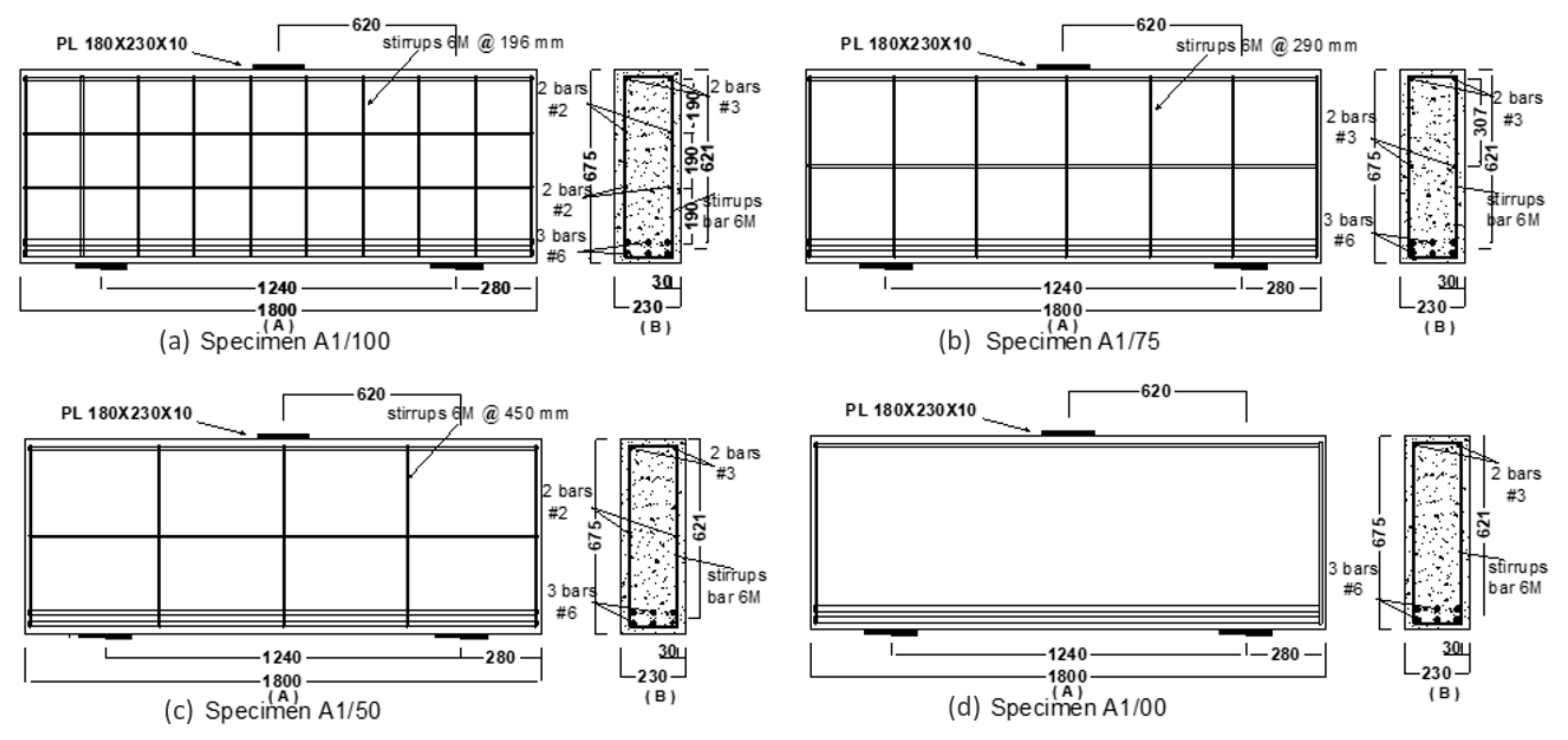
3. Experimental Program

Studies on the influence of web reinforcement on FRP-reinforced concrete deep beam behaviour are very limited compared to work that has been done on steel-reinforced concrete deep beams. The experiments were conducted at Concordia University’s Structures Laboratory [30]. We investigated the effects of two parameters (the shear span depth ratio (a/d) and the amount of the FRP web reinforcements) on the structural behavior of concrete deep beams. This study also investigated the efficiency of the proposed strut and tie model in designing FRP-reinforced concrete deep beams and compares it to the design method for regular FRP-reinforced beams. The proposed strut and tie model is a modification of the STM model provided in ACI 318-14 2104 [9] and CAN/CSA-S806-12 [5]. Test beams were designed with a sufficient width (230 mm) for all beams to avoid the effect of lateral buckling and were thicker than the recommended minimum thickness specified by code. All the beams had a total span of 1800 mm. However, the depths were altered to obtain shear span-to-depth ratios (a/d) of 1. The depth d was 621 mm to achieve a a/d ratio equal to one. The beams had a longitudinal main GFRP reinforcement ratio of ρ = 1.2 percent. Figure 1 shows the specimen A1 in its position ready for testing.
Three of the beams had web reinforcements. The results of steel-reinforced deep beams and earlier studies have indicated the importance of web reinforcement in predicting the behavior of-reinforced concrete deep beams such as the deflection at midspan size, failure styles, and ultimate load. The stirrups were all GFRP and size No 2# [6 mm in diameter]. The amount of web reinforcements was varied from zero in Specimen A1/00 to 6 M stirrups @ 196 mm and 3 layers of horizontal bars in A1/100. In the other two specimens, intermediate levels of web reinforcements were used. The top reinforcements consisted of two size No 3# [10 mm in diameter] GFRP bars. The details of the specimens are given in Table 1, and the full details of the specimen dimensions and the reinforcement are illustrated in Figure 2.

3.1. Material Properties

The longitudinal and web reinforcements in this research were all made of sand-coated GFRP. The GFRP longitudinal rebars at the top and bottom of the four deep beams were assembled from three sizes: No. 3, No. 4, and No. 6. The stirrups were fabricated from GFRP bars of size No. 2. The characteristics of the GFRP used in this study, according to the properties given by the supplier, are summarized in Table 2.
All four specimens were cast using a ready-mix concrete with a target of compressive strength about 35 MPa and was supplied by a local company. All the beams were constructed using the same concrete. The actual compressive strength was obtained by testing the cylinders on the first and last day of the beam experimental test.

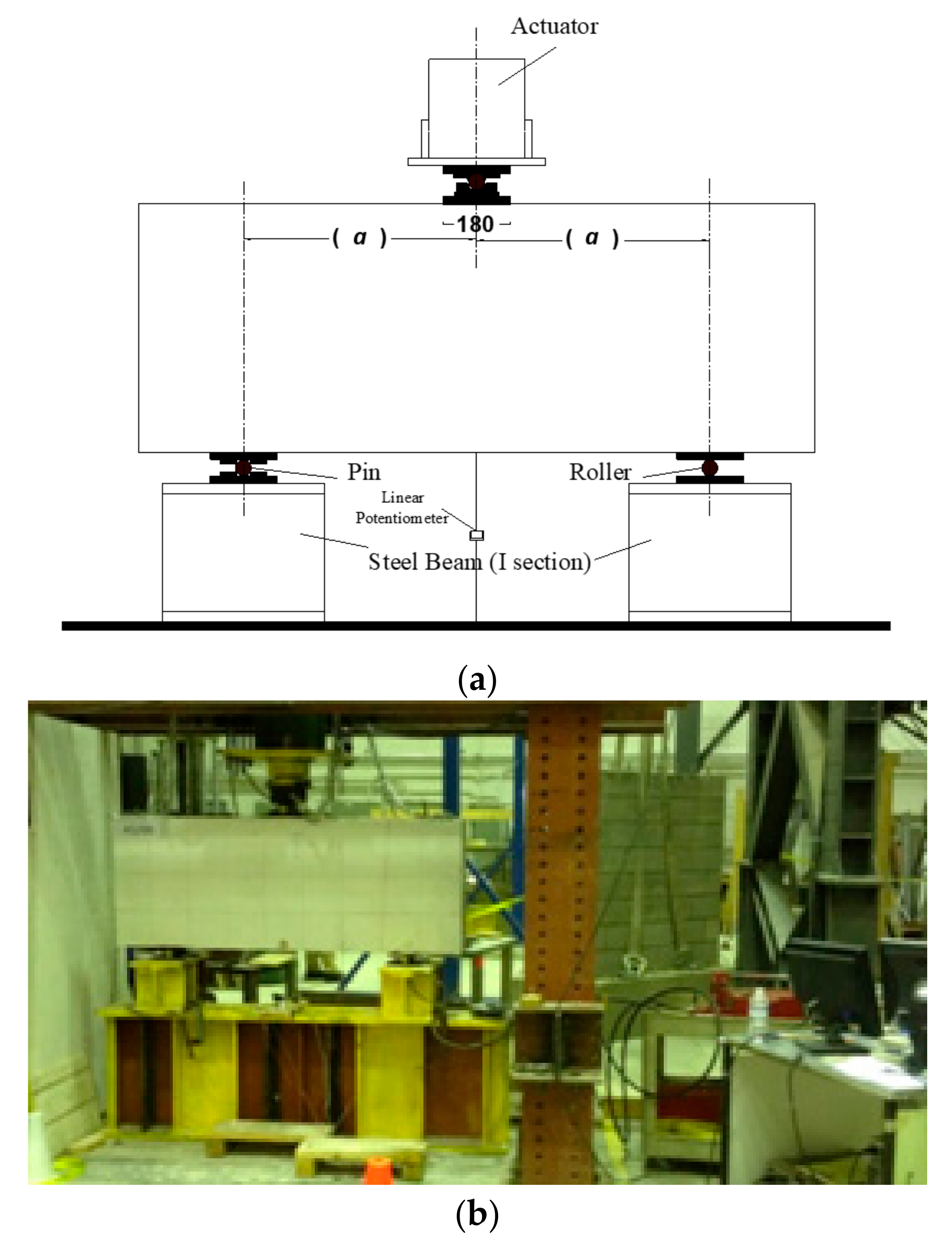
3.2. Testing Procedure

Figure 1 illustrates that each specimen was prepared for testing according to a standardized procedure in which they were supported by a pin and roller support at opposite ends. To induce failure, a concentrated vertical load was applied at the midpoint of the top the beams using a three-point loading configuration. To guarantee accurate application of the load at the loading point, a roller steel restraint was utilized in the horizontal direction. The use of this restraint eliminated the possibility of lateral forces or bending moments being introduced, thereby producing consistent and reliable results. For the concentrated load, a compression testing machine with a 2000 kN capacity was used in this experiment. Steel plates were placed at the point load and the support location. Using the three-point loading (loading point and at the supports) method, steel plates were attached by plaster paste to obtain uniform contact and to prevent the specimens from slipping. The steel plates had dimensions of 180 mm length, 230 mm width, and 30 mm height. To lower the chances of a stability failure, a centralization of the beam position and its vertical alignment were verified during the erecting process. Both surfaces of the beam were painted white, then with stripes to record the development of cracks throughout the testing process.

4. Results and Discussion

The outcomes of the FRP-reinforced concrete deep beam experiments are summarized in Table 3. Table 3 contains the material properties, the modes of failure, the initial cracking (flexural and diagonal) shear strength Vcr, and the ultimate shear strength Vn of the nine specimens. The shear capacity of each beam was measured at the middle of the distance between the support and the load. The support reaction was calculated from the load-cell reading together with the portion of the beam weight that represents the shear capacity at any stage of loading.

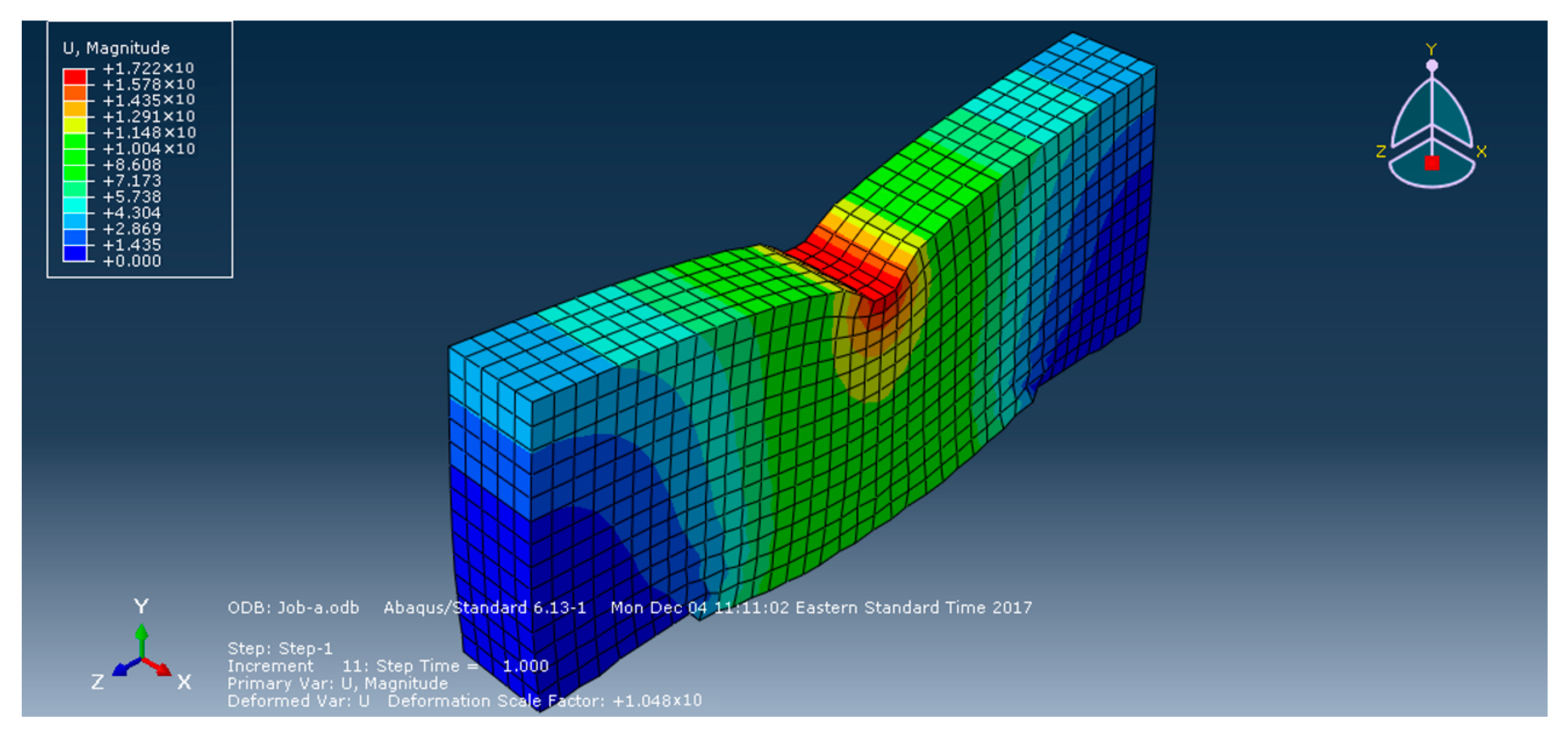
4.1. Finite Element Modelling

The specimens were modeled using the nonlinear Finite Element (FE) analysis system (ABAQUS software) to estimate their capacities which were compared to the experimental results. Continuum (solid) element C3D8I, available in ABAQUS software, was used to model the concrete. To simulate the concrete behavior, a Concrete Damaged Plasticity Model was used. The FE model had the capability to account for crushing in compression and cracking in tension. Additionally, the inelastic behavior of concrete was simulated using the model of isotropic damaged elasticity combined with isotropic tensile and compressive plasticity. The truss element, T3D2, available in ABAQUS was used to define the reinforcement bars in concrete. It was assumed that the bond between the reinforcing bars and concrete was perfect and there was no debonding or slip between concrete and the rebars. This assumption is consistent with what was observed in the tests. The behavior of the reinforcing bar material can be described as elastic for FRP bars as they did not yield. To simulate the bond between the rebars and concrete, ABAQUS software provides the ability to embed rebar-reinforced elements into the concrete solid element with ease and convenience. Figure 3 shows a sample Finite Element model created for Specimen A1/00. Other specimens had a similar configuration with different arrangements of the web reinforcement.
The ultimate loads and deflections acquired from the FE model and the ratio of the experimental results and the FE model for each of the test specimens. There was a good convergence between the maximum loads and deflections predicted by the model and those obtained from the tests.
The findings of the analytical results converged to all specimens’ results, where the mean ratio of experimental and predicted ultimate load capacity (by ABAQUS) Pu was 1.01 at a standard deviation of 0.04.

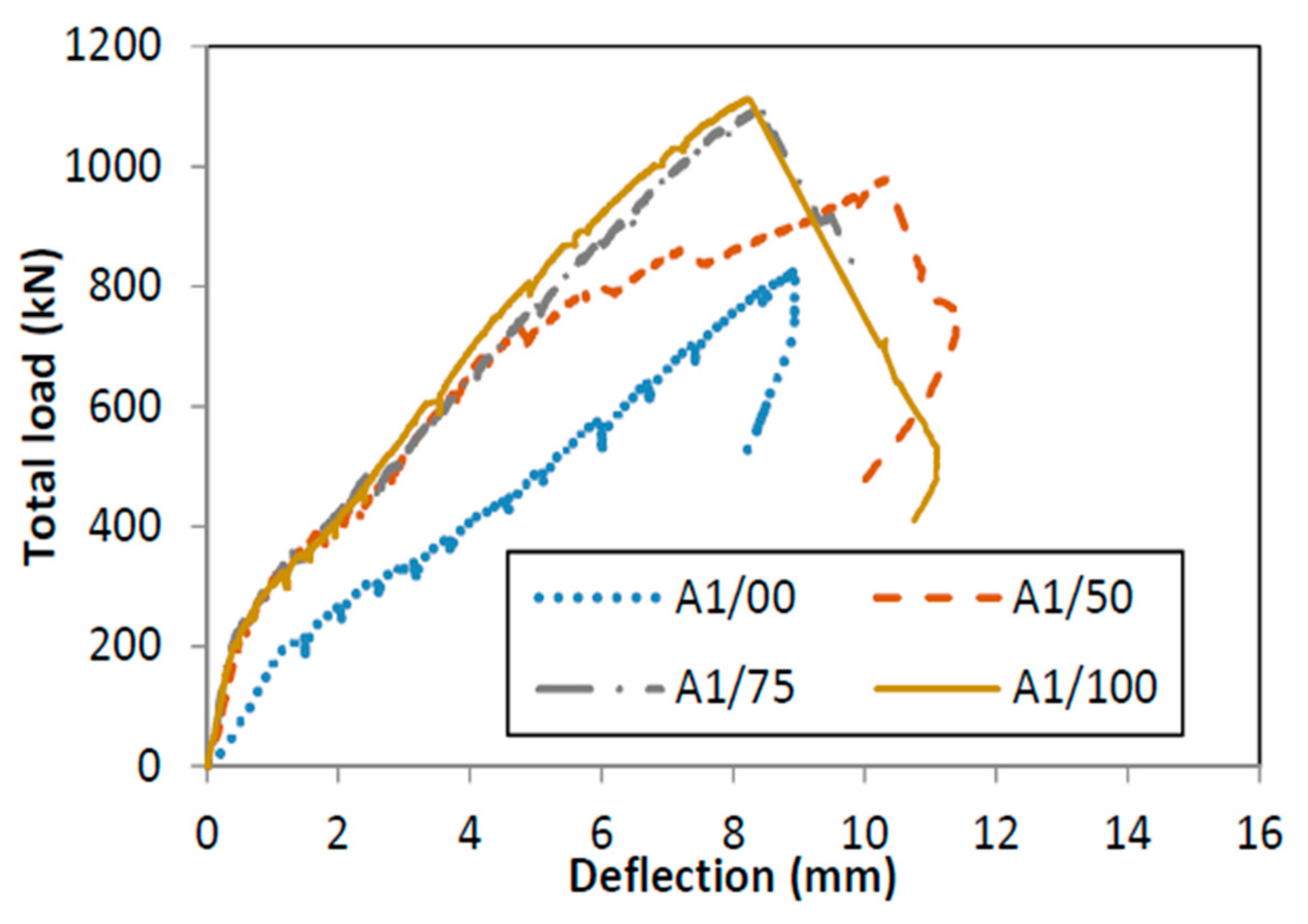
4.2. Experimental Results

Each beam was equipped with external instrumentation comprising two Linear Variable Differential Transformers (LVDTs) positioned at mid-span to measure the beam deflection. The two LVDTs were connected on either side of the beam to record the differential displacement of both sides during the test. The full stroke range (F.S) of the potentiometers was 635 mm with an accuracy of 0.25% of F.S. The load versus the mid-span deflection curves of all beams are shown in Figure 4 and the details of the experimental results are shown in Table 3.
After reaching Pu and failure, the load started to drop, with a simultaneous increase in the deflection in all samples. As can be seen from Figure 4, the beams exhibited a steep load–deflection curve. Figure 4 shows that the ultimate deflection for beams with web reinforcement steadily increased. It was mainly due to the increased capacity of the beams with a higher amount of web reinforcement. These results show that the web reinforcement played a significant role in affecting the beam stiffness. This behavior reflects what was previously observed by Mohamed et al. [15] in which the specimens without web reinforcement showed a lower stiffness than the specimens with horizontal web reinforcements. Additionally, this behavior is akin to that observed for steel-reinforced deep beams where Smith and Vantsiotis [17] and Tan et al. [18] have noticed that the beam stiffness increases for beams with web reinforcements. They also have recommended that a sufficient amount of vertical and horizontal web reinforcement is needed to enhance beam stiffness and to control cracks.

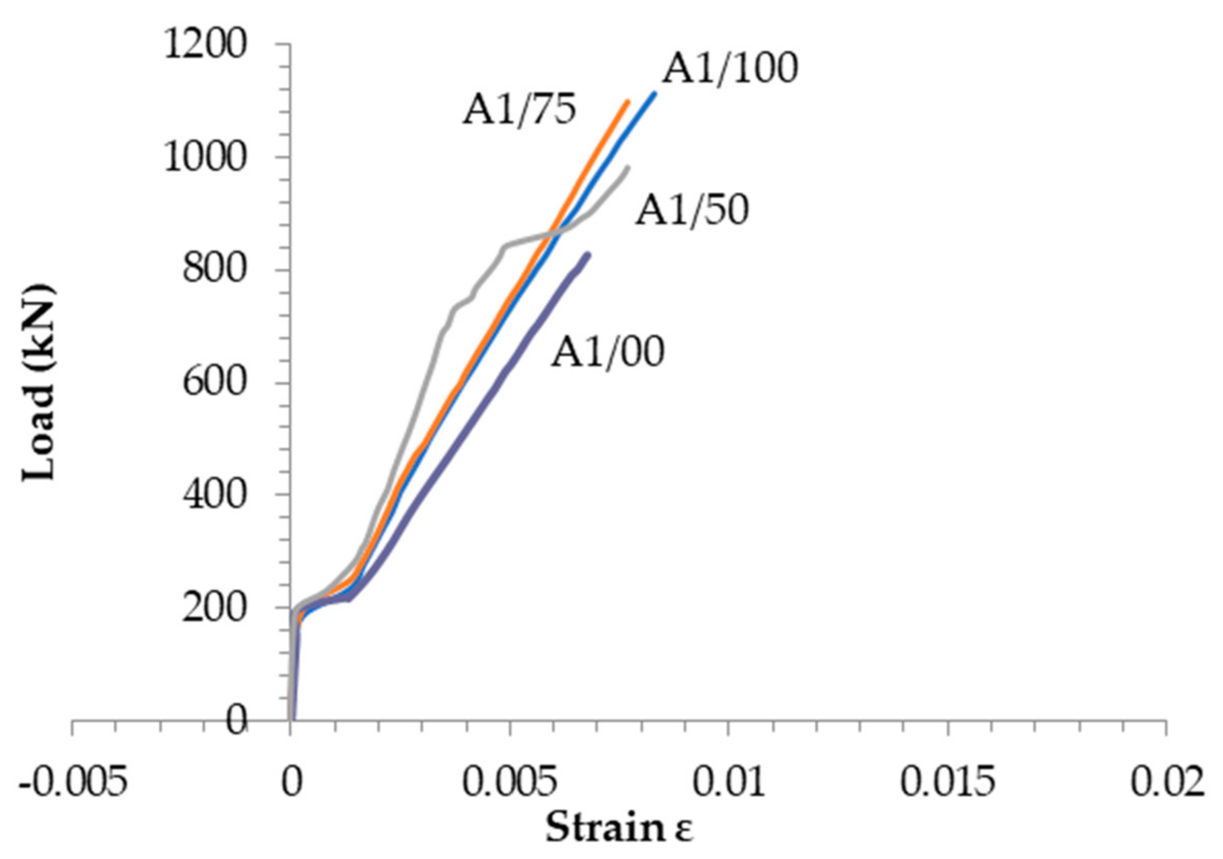
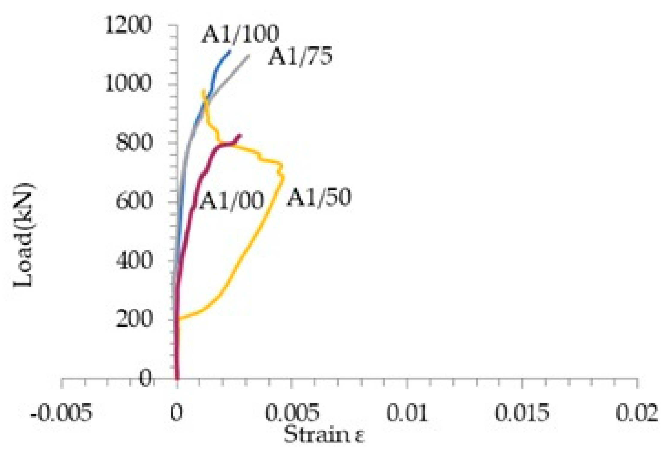
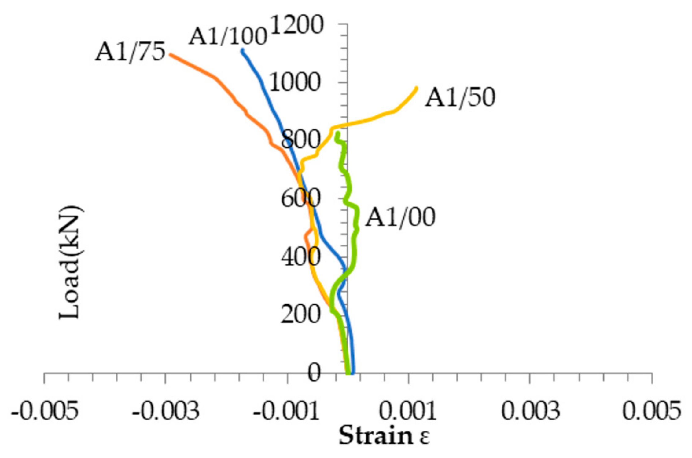
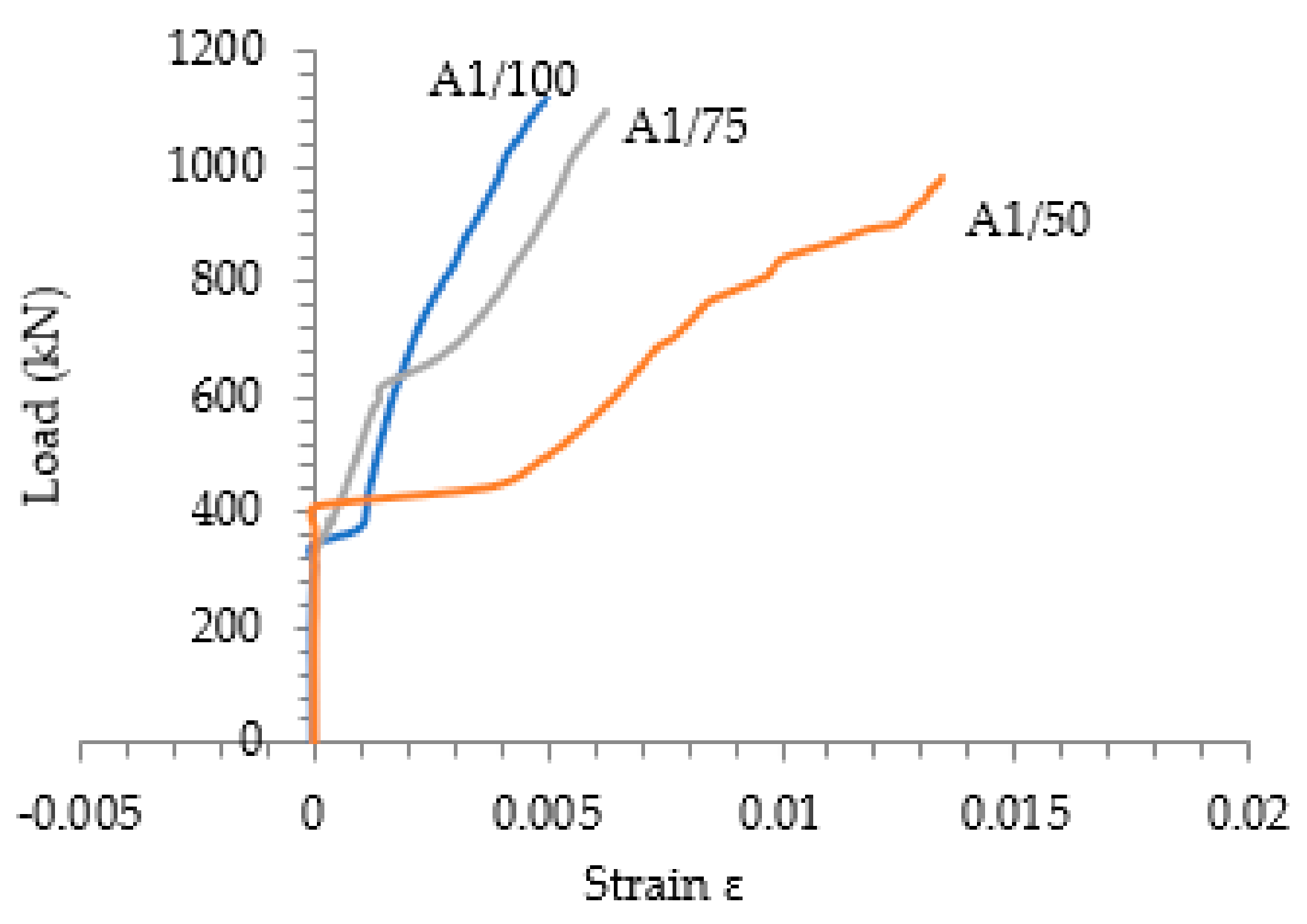
4.3. Load-Strain in FRP Response

The strain response of the longitudinal reinforcements, measured at the mid-span at different loading stages is shown in Figure 5, for all four specimens. When the flexural crack occurred, the tensile strain in the rebar at mid-span increased suddenly and then followed a linear pattern of increase as loading increased. The sudden shift or increase in the strain in the beams without or with less web reinforcements corresponded well with the initial flexural cracks observed from the experiment. The strain shift was observed to be less than that of beams with more web reinforcements. The beams that had additional web reinforcements exhibited longer initial flexural cracks in comparison to the ones with no or limited reinforcements. In addition, a higher quantity of web reinforcements increased the beam stiffness.
The results demonstrated that only 54.19% of the ultimate manufactured strength of the GFRP bar had been achieved in beams A1/100, 50.29% in A1/75, 50.36% in A1/50 and 44.38% in A1/00. Compared to the experimental results, the reduction, which is about 65% of the manufactured ultimate tensile strength Fu according to clause 8.5.3.1 of the Canadian code CSA-S806-12 [5], was consistent.
Figure 6 illustrates the response of the strain gauges at the development length of the reinforcement bar beyond the supporting plate (the nodal zone) for four specimens. Figure 4 indicates that strain in the reinforcement bars in the end node region did not exceed 30% of the ultimate strain for the four specimens. These results indicate that the bar anchorage was adequate. The bars were exposed to lateral pressure resulting in a higher bond strength due to the compression zone (node) that formed at the supporting plate.
Figure 7 shows the strain–load relationship of the top longitudinal GFRP reinforcement rebars for the four beams. The negative strains observed in the bar near the loading plate in the nodal zone provide evidence that this area was under lateral pressure caused by the loading plate and two compression struts that originated from the loading points. Even though the failure of Specimens A1/100, A1/75 occurred in this zone, the longitudinal reinforcement bars at the top were not significantly deformed.
The strains in the GFRP web reinforcements in four specimens are shown in Figure 8. Only the FRP web reinforcement on the left half of two beams will be discussed here, as the strain in the web reinforcements in this part is higher than that in the right half because the left end was more restrained due to the hinge support while the right end was on rollers. The tensile strains detected in the web reinforcements on the left-hand side of the specimens, in the assumed direction of the main struts, were quite low until a particular level of load was applied, and then they began to increase with the increasing load levels. These levels of loads coincided approximately with those corresponding to the initiation of the diagonal cracks that was revealed from the beam results.
From Figure 8, the strain in the vertical web reinforcement in specimen A1/50 reached 70.43% of εfu (i.e., the ultimate strain of the GFRP bars as specified by the manufacturer), while in the A1/75 and A1/100 specimens, the stain in the stirrups reached only 32.79% and 26.14% of εfu, respectively. Before failure occurred, some of the strain gauges indicated that they were out of scale because the wires that intersecting the cracks were damaged.

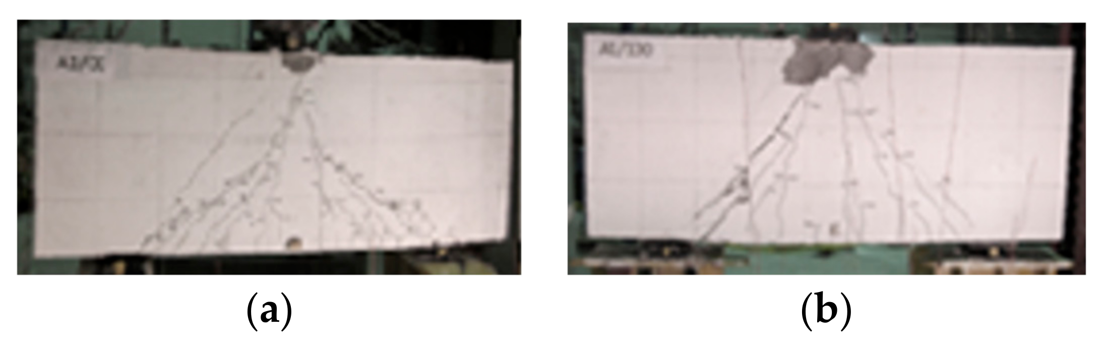
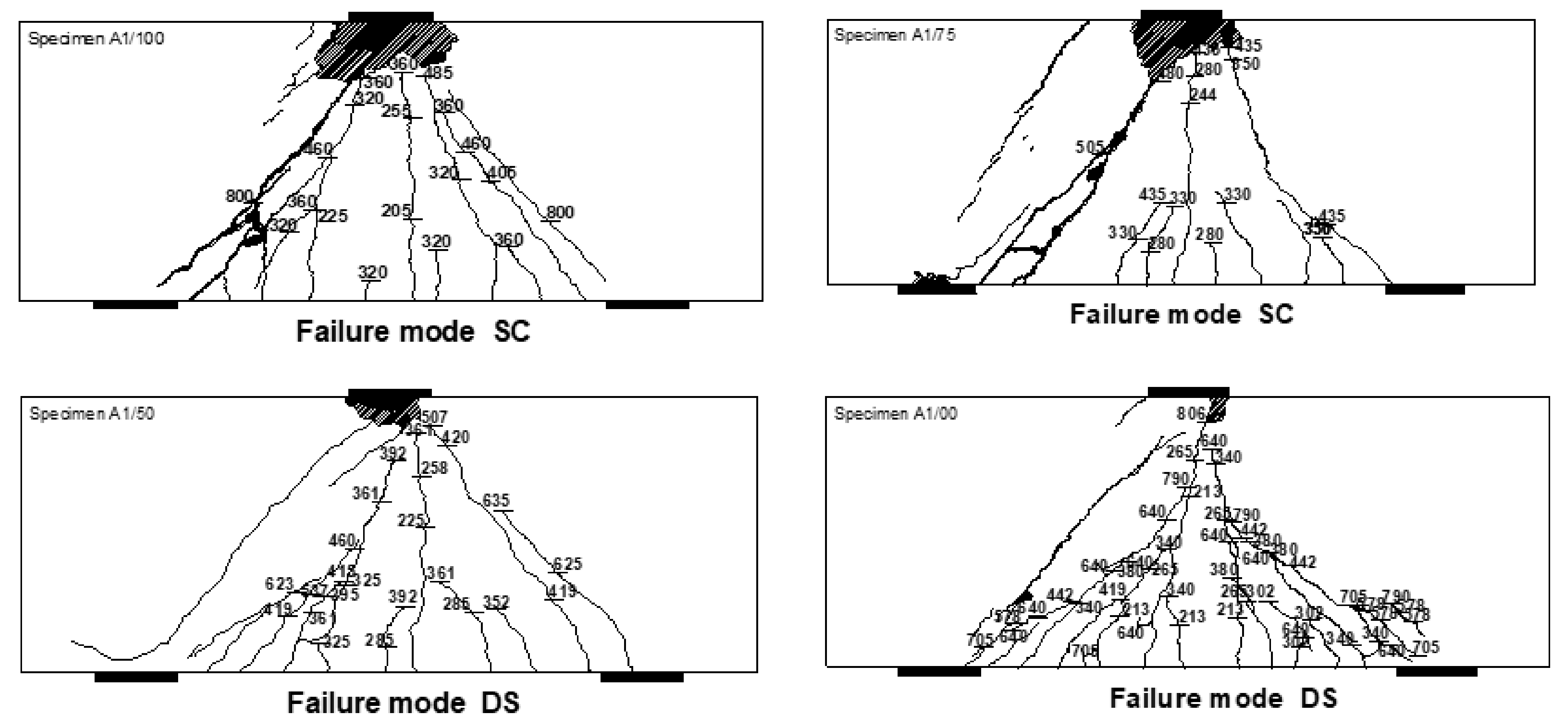
4.4. Crack Developments

Earlier works, Refs. [16,17,18,19,20], have indicated that web reinforcement has some influence on controlling the crack and the crack width of steel-reinforced deep beams. Although opinions differ on the impact of web reinforcements in controlling cracks, a prevailing view among experts is that their impact on crack width and control is comparable to their effect on beam stiffness. Regarding FRP-RC deep beams, Mohamed et al. [5] have noted that web reinforcement had a noteworthy impact on controlling the crack width in concrete deep beams-reinforced with GFRP. The comparison of the crack patterns among the beams studied in [5] has indicated that in the GFRP-reinforced deep beams, the web reinforcements are essential in governing the crack width.
Figure 9 and Figure 10 illustrate the observed crack patterns in the tested specimens. While Figure 9 shows some sample images of the crack patterns mapped on some of the specimens, the details of the crack patterns at various load levels observed throughout the experiments are shown in Figure 10. At about 20% of the ultimate load (Pmax) was when the first flexural crack at the mid-span of beams started to propagate. As the load progressively increased on all specimens, fresh flexural cracks began to develop and lengthened towards the loading plate as the load increased. As loading progressed in each specimen, a diagonal crack started to emerge around the internal boundary of the support plate and progressed in the direction of the loading plate.
With increasing levels of the applied load, there was an increase in the number of flexural and diagonal cracks, and the pre-existing cracks expanded or became longer in the direction of the compression face of the beams. After reaching approximately 65% of Pmax, the formation of new cracks and the propagation of the existing ones eventually stopped, and the pre-existing ones continued to expand until the point of failure.
In general, the crack patterns at failure were found to be similar in all specimens, while differing in their spread based on the levels of web reinforcements. The specimen without web reinforcements was more extensively cracked than those with web reinforcements. This confirmed the effect of the web reinforcement on controlling the cracks by resisting the transverse tensile stresses developed in the web reinforcements across the cracks.

4.5. Failure Modes

All the specimens’ failure modes are listed in the last column of Table 3. The beams exhibited two types of shear failure modes: shear compression failure, and diagonal splitting failure. These failure modes are brittle in nature. Specimens A1/00 and A1/50 failed via the diagonal splitting mode of failure. The failure occurred at the middle of the beam, parallel to the strut. The observed failure mode exhibits the same splitting failure that occurs in concrete cylinders subjected to tensile splitting tests. The failure occurred suddenly but was not as explosive as the shear compression failure or the crushing strut failure. This mode of failure occurred due to insufficient web reinforcement which could not resist the tensile stresses in cracked concrete.
The specimen A1/75 failed by crushing of the nodes and occurred in the concrete at the end of the strut. The crushing of the strut was accompanied by a loud sound. The shear compression failure (node failure) occurred close to the loading or bearing plate, which has been designated by hatch marks in Figure 7. The results demonstrate that Specimen A1/100, which has the highest amount of web reinforcements, experienced a relatively similar failure mode as that observed from beam A1/75. However, it sustained greater loads than beam A1/75.

5. Conclusions

The present article reports the findings of an experimental investigation conducted on deep beams-reinforced with fiber-reinforced polymer. The main objective of the present work was to study the effect of FRP web reinforcements, ρw, on the behavior of FRP-RC deep beams. The numerical models of the specimens tested here were also modelled using the Finite Element method. The conclusions drawn from the comparison of the test results with the Finite Element model results are as follows:
  • The experimental results indicated that the FRP web reinforcement had a noticeable yet minor influence on the beam stiffness. Specifically, the deflection of the beams with web reinforcement exhibited a gradual increase.
  • In comparison to the experimental investigations, the Finite Element model produces comparable, but slightly conservative, estimates of the ultimate shear strength.
  • The strain in the FRP web reinforcements were found to be lower than the percentage of the manufacturer-specified ultimate tensile strength Fu as recommended in Clause 8.5.3.1 of the CAN/CSA-S806-12 code and was adequate in accordance with the results.
  • The increase in the tensile strains in the region of the assumed direction of the main struts and in the main longitudinal FRP rebars located in two different layers exhibited mostly the same stress.
  • Web reinforcement has a significant effect on crack control, propagation, and distribution. The deep beams without or with less web reinforcement exhibited more damaging failure modes (e.g., diagonal splitting) compared to those with adequate web reinforcements.
  • The presence of web reinforcement resulted in an increase in the ultimate shear strength of the tested beams.
  • The failure modes were found to be affected by the amount of web reinforcements. An increased amount of web reinforcements helps prevent diagonal splitting failures.

Author Contributions

F.L. and A.A.-S. developed the methodology, concept, and experimental and numerical work. A.A.-S. and A.B. aided in developing the methodology, concept, and analysis of the results. A.B supervised this study. All authors have read and agreed to the published version of the manuscript.

Funding

This research received no external funding.

Data Availability Statement

The data presented in this study are available on request from the corresponding author.

Conflicts of Interest

The authors declare no conflict of interest.

References

  1. Nawy, E.G. Reinforced Concrete: A Fundamental Approach, 5th ed.; Prentice Hall: Hoboken, NJ, USA, 2005; 824p. [Google Scholar]
  2. CAN/CSA S806-02; Design and Construction of Building Components with Fiber-Reinforced Polymers. Canadian Standards Association: Mississauga, ON, Canada, 2002; 218p.
  3. ACI Committee 440. Guide for the Design and Construction of Concrete Reinforced with FRP Bars; American Concrete Institute: Farmington Hills, MI, USA, 2015; 206p. [Google Scholar]
  4. ISIS Canada Research Network. Design Manual No. 3: Reinforcing Concrete Structures with Fibre-Reinforced Polymers; University of Manitoba: Winnipeg, MB, Canada, 2007; Volume 2, 151p. [Google Scholar]
  5. CAN/CSA S806-12; Design and Construction of Building Components with Fiber-Reinforced Polymers. Canadian Standards Association: Mississauga, ON, Canada, 2012; 206p.
  6. ACI Committee 440. Guide for the Design and Construction of Concrete Reinforced with FRP Bars; American Concrete Institute: Farmington Hills, MI, USA, 2006; 88p. [Google Scholar]
  7. ACI Committee 318. Building Code Requirements for Structural Concrete (ACI 318-14) and Commentary (318R-14); American Concrete Institute: Farmington Hills, MI, USA, 2014; 524p. [Google Scholar]
  8. European Standard EN1992-1-1; Euro Code 2: Design of Concrete Structures—Part 1-1: General Rules and Rules for Buildings. European Committee for Standardization: Luxembourg, 2004.
  9. CAN/CSA CAN3-A23.3-04; Design of Concrete Structures for Buildings with Explanatory Notes. Canadian Standards Association: Rexdale, ON, Canada, 2004.
  10. Nehdi, M.; Omeman, Z.; El-Chabib, H. Optimal efficiency factor in strut-and-tie model for FRP-reinforced concrete short beams with (1.5\a/d\2.5). Mater. Struct. 2008, 41, 1713–1727. [Google Scholar] [CrossRef]
  11. El-Sayed, A.K.; El-Salakawy, E.F.; Benmokrane, B. Shear strength of fibre-reinforced polymer reinforced concrete deep beams without web reinforcement. Civ. Eng. Can. J. 2012, 39, 546–555. [Google Scholar] [CrossRef]
  12. Andermatt, M.; Lubell, A. Behavior of concrete deep beams reinforced with internal fiber-reinforced polymer—Experimental study. ACI Struct. J. 2013, 110, 585–594. [Google Scholar]
  13. Farghaly, S.A.; Benmokrane, B. Shear Behavior of FRP-Reinforced Concrete Deep Beams without Web Reinforcement. J. Compos. Constr. 2013, 17, 04013015. [Google Scholar] [CrossRef]
  14. Kim, D.J.; Lee, J.; Lee, Y.H. Effectiveness factor of strut-and-tie model for concrete deep beams reinforced with FRP bars. Compos. Part B 2014, 56, 117–125. [Google Scholar] [CrossRef]
  15. Mohamed, K.; Farghaly, S.A.; Benmokrane, B. Effect of Vertical and Horizontal Web Reinforcement on the Strength and Deformation of Concrete Deep Beams Reinforced with GFRP Bars. J. Struct. Eng. 2017, 143, 04017079, Erratum in Struct. J. 2017, 41, 1713–1727. [Google Scholar] [CrossRef]
  16. Latosh, F. Structural Behaviour of Conventional and FRP- Reinforced Concrete Deep Beams. Ph.D. Thesis, Concordia University, Montreal, QC, Canada, 2014. [Google Scholar]
  17. Smith, K.N.; Vantsiotis, A.S. Shear strength of deep beams. ACI Struct. J. 1983, 79, 201–213. [Google Scholar]
  18. Tan, K.H.; Kong, F.K.; Teng, S.; Weng, L.W. Effect of Web Reinforcement on High Strength Concrete Deep Beams. ACI Struct. J. 1997, 94, 572–581. [Google Scholar]
  19. Shin, S.W.; Lee, K.S.; Moon, J.; Ghosh, S.K. Shear strength of reinforced high-strength concrete beams with shear span-to-depth ratios between 1.5 and 2.5. ACI Struct. J. 1999, 96, 549–556. [Google Scholar]
  20. Kong, F.K.; Robins, P.J.; Cole, D.F. Web Reinforcement Effects on Deep Beams. ACI Struct. J. 1970, 67, 1010–1018. [Google Scholar]
  21. Rogowsky, D.M.; MacGregor, J.G.; Ong, S.Y. Tests of Reinforced Concrete Deep Beams. ACI Struct. J. 1986, 83, 614–623. [Google Scholar]
  22. AlHamaydeh, M.; Markou, G.; Bakas, N.; Papadrakakis, M. AI-based shear capacity of FRP-reinforced concrete deep beams without stirrups. Eng. Struct. 2022, 264, 114441. [Google Scholar] [CrossRef]
  23. Golafshani, E.M.; Ashour, A. A feasibility study of BBP for predicting shear capacity of FRP reinforced concrete beams without stirrups. Adv. Eng. Softw. 2016, 97, 29–39. [Google Scholar] [CrossRef]
  24. Dhahir, M.K. Strut and tie modeling of deep beams shear strengthened with FRP laminates. Compos. Struct. 2018, 193, 247–259. [Google Scholar] [CrossRef]
  25. Jin, L.; Lei, Y.; Song, B.; Jiang, X.A.; Xiuli, D.U. Meso-scale modelling of size effect on shear behavior of basalt fiber reinforced concrete deep beams. Compos. Struct. 2022, 304, 116440. [Google Scholar] [CrossRef]
  26. Alam, M.S.; Sultana, N.; Hossain, S.Z. Bayesian optimization algorithm based support vector regression analysis for estimation of shear capacity of FRP reinforced concrete members. Appl. Soft Comput. 2021, 105, 107281. [Google Scholar] [CrossRef]
  27. Albidah, A.; Abadel, A.; Abbas, H.; Almusallam, T.; Al-Salloum, Y. Experimental and analytical study of strengthening schemes for shear deficient RC deep beams. Constr. Build. Mater. 2019, 216, 673–686. [Google Scholar] [CrossRef]
  28. Zinkaah, O.H.; Alridha, Z.; Alhawat, M. Numerical and theoretical analysis of FRP reinforced geopolymer concrete beams. Case Stud. Constr. Mater. 2022, 16, e01052. [Google Scholar] [CrossRef]
  29. Zhang, G.; Ali, Z.H.; Aldlemy, M.S.; Mussa, M.H.; Salih, S.Q.; Hameed, M.M.; Al-Khafaji, Z.S.; Yaseen, Z.M. Reinforced concrete deep beam shear strength capacity modelling using an integrative bio-inspired algorithm with an artificial intelligence model. Eng. Comput. 2020, 38, 15–28. [Google Scholar] [CrossRef]
  30. Algamati, M.; Al-Sakkaf, A.; Mohammed Abdelkader, E.; Bagchi, A. Studying and Analyzing the Seismic Performance of Concrete Moment-Resisting Frame Buildings. CivilEng 2023, 4, 34–54. [Google Scholar] [CrossRef]
Figure 1. Typical test setup for beams: (a) schematic elevation view, (b) photo.
Civileng 04 00030 g001
Figure 2. Reinforcement details and specimens’ geometry of four beams: (a) Specimen A1/100, (b) Specimen A1/75, (c) Specimen A1/50 and (d) Specimen A1/00; meanwhile (A) showed the cross section and (B) showed the elevation in each subfigure.
Civileng 04 00030 g002
Figure 3. A sample Finite Element model used in modelling Sample A1/00 U. Magnitude.
Civileng 04 00030 g003
Figure 4. Total Load vs. Deflection Diagrams for Four Beams.
Civileng 04 00030 g004
Figure 5. Load vs. Strain gage at the middle of the bottom GFRP Rebars.
Civileng 04 00030 g005
Figure 6. Load–Strain response at the end of the main tension GFRP reinforcement of specimens.
Civileng 04 00030 g006
Figure 7. Load–Strain response of the top longitudinal GFRP reinforcement of specimens.
Civileng 04 00030 g007
Figure 8. Load–Strain response in the vertical GFRP web reinforcement on left half of the specimens.
Civileng 04 00030 g008
Figure 9. Sample images of the crack patterns at failure: (a) Specimen A1/00 and (b) Specimen A1/100.
Civileng 04 00030 g009
Figure 10. Crack patterns observed in the tested specimens (CS = crushing of strut failure. DS = diagonal splitting failure).
Civileng 04 00030 g010
Table 1. Reinforcements, Concrete, and Geometry Details.
Specimen Nofc
(MPa)
b
(mm)
d
(mm)
Le
(mm)
a/dMain
Reinforcement
ffu
(MPa)
εfuVertical &
Horizontal
Reinforcement
Ρ
(%)
Ρw
(%)
A1/10049.8230621124013 # 6(19 mm)
3# 6 (19 mm)
6560.01536 M@196 mm
6 M@190 mm
1.1970.131
A1/7552.2230621124013 # 6(19 mm)
3# 6 (19 mm)
6560.01536 M@290 mm
10 M@300 mm
1.1970.095
A1/5052.5230621124013 # 6(19 mm)
3# 6 (19 mm)
6560.01536 M@450 mm
6 M@300 mm
1.1970.061
A1/0052.7230621124013 # 6(19 mm)
3# 6 (19 mm)
6560.0153N/A1.197N/A
Table 2. Manufactured properties of GFRP bars.
Soft Metric SizeDiameter
(mm)
Area
(mm2)
Tensile Modulus
of Elasticity Et
(GPa)
Ultimate Tensile
Strength Fu
(MPa)
Ultimate Strain in
Tension εFu
(%)
Poisson’s
Ratio μ
#66.3531.746.18741.900.25
#109.5271.345.48561.890.21
#1312.70126.746.37081.700.26
#1919.0528547.66561.530.25
Table 3. Summary of all Experimental (EXP) and Numerical (FEM) Results.
Specimen No.PuEXP
(kN)
Δ
(mm)
VuEXP
(kN)
PuFEM
(kN)
PuEXP/PuFEMMode of Failure
A1/1001113.808.22560.251118.780.99Shear Compression
A1/751098.078.43552.391120.630.98Shear Compression
A1/50980.6810.33493.691040.490.94Diagonal Splitting
A1/00827.078.91416.89800.561.03Diagonal Splitting
Disclaimer/Publisher’s Note: The statements, opinions and data contained in all publications are solely those of the individual author(s) and contributor(s) and not of MDPI and/or the editor(s). MDPI and/or the editor(s) disclaim responsibility for any injury to people or property resulting from any ideas, methods, instructions or products referred to in the content.

