
Experimental Evaluation of Post-Earthquake Fire on Reinforced Concrete Structures—A Review


RISCO, Civil Engineering Department, University of Aveiro, 3810-193 Aveiro, Portugal
*
Author to whom correspondence should be addressed.
CivilEng 2023, 4(2), 469-482; https://doi.org/10.3390/civileng4020027
Submission received: 17 February 2023
/
Revised: 12 April 2023
/
Accepted: 19 April 2023
/
Published: 26 April 2023
(This article belongs to the Special Issue Connections in Concrete Volume 2)
Abstract
:This review aims to investigate the recent advancements in the performance of earthquake-damaged reinforced concrete structures subjected to fire loading and the damages that are induced by fire to reinforced concrete structural elements with damage due to seismic loads. The first part of the paper provides a general understanding of the Post-Earthquake Fire (PEF) effect on reinforced concrete structures, and some statistics regarding the previous earthquake casualties and amounts of destruction in different regions of the world are addressed. In the second part of the investigation, an in-depth review of the experimental and numerical procedures of PEF analysis in concrete columns, beams, slabs, and full-scale RC frames and the types of damages in RC members due to PEF have been presented, giving a general review of the results and conclusions in previous research in PEF in different reinforced concrete structures. In the end is discussed the concept of hybrid fire simulation, its applications in engineering problems, the methodologies that consider full interaction effects as well as recent breakthroughs in studying PEF using Real-Time Hybrid Simulation.
1. Introduction
Post-Earthquake Fire (PEF) may cause severe damage in reinforced concrete (RC) structures in terms of cracks and spalling, and such damages may lead to the total collapse of the RC structure. Previous research works have mainly emphasised the analysis of the behaviour of steel structures concerning the PEF effects, but in RC structures, several open questions still need to be deeply investigated and answered [1]. To better understand the fire effects on earthquake-induced damages on RC structural elements, the concrete and rebar material behaviour and thermal properties concerning heating must be considered. Due to the high thermal inertia of concrete, the fire resistance of concrete members is often considered to be satisfactory in an ordinary fire hazard. However, the thermal properties of concrete are generally independent of its mechanical properties and the effects introduced by the seismic damage on an RC member, such as cracking and loss of reinforcement cover, may contribute to rapid heat penetration into the damaged member. The PEF effects have also been significant in some famous earthquakes, namely in 1906 in San Francisco, in 1923 in Tokyo, in 1971 in San Fernando, and in 1994 in Northbridge [2]. A disastrous fire emerged due to the San Francisco earthquake which destroyed 80% of the city and took more than 3000 lives and continued for several days, and the property damage was estimated at US $500,000,000 in 1906. In another similar case, also the fire following the devastating earthquake of Kanto earthquake in Tokyo that occurred in 1923 took more than 140,000 lives. The most famous earthquakes in California experienced a tremendous number of fire incidents, including the San Fernando 1971 and Northridge 1994 earthquakes. Recent earthquakes in Loma Prieta (California 1989), Hanshin/Kobe (Japan 1995), Marmara (Turkey 1999), and Christchurch (New Zealand 2011) earthquakes were all followed by significant fires. The reported duration changes from a few hours up to even three days. Studies of the future large-scale earthquakes in San Francisco and Tokyo illustrate that the fire after an earthquake will act as a pivotal factor in the casualties and property damages [3]. In another disaster, the Kobe earthquake (17 January 1995), more than 500 people were killed by PEF [4]. Considering the casualties of previous earthquakes and the damages observed, it is of utmost importance to further investigate fire behaviour on damaged RC elements after seismic loads and provide solutions to mitigate the fire effects on RC structures after the earthquake. Another relatively recent earthquake affected by FFE took place in Eastern Japan in 2011 with a Mw 9 magnitude which was followed by a tsunami that caused several accidents, especially in industrial areas. The Fukushima Daiichi nuclear power plant suffered severe damages, and at least three nuclear reactors exploded due to the emission of hydrogen gas and several oil refineries were damaged due to PEF effects induced by the tsunami.
2. Background
The concrete behaviour at high temperatures is very complex, affecting the structure’s overall behaviour during the heating process. The fire behaviour of an earthquake-damaged structure is related to the residual bearing capacity. The behaviour of concrete subjected to elevated temperature is also considered a very sophisticated issue because it not only responds to physical changes such as expansion but also experiences a series of chemical changes, and in PEF experimental investigations of RC structures, it is crucial to determine the temperature conditions and define whether it changes with time. Each component of concrete, i.e., the cement, aggregate, and moisture, share their reactions differently. Thus, in the analysis of PEF in RC structures, the thermal properties of concrete and rebar also are of great importance to pay into account. During the PEF testing, the performance of the damaged structure concerning the imposed heating is evaluated.
Testing RC structures at high temperatures can be accomplished in several scenarios that rely on the factors related to the test. Tests can be implemented on different structural elements such as beams, columns, slabs, cylinders, and full-scale models. For example, the main expected damage to RC beams due to earthquakes may include cracks and concrete spalling in the plastic hinge zones. The crack and spalling dimensions and location in terms of depth and width can be obtained and included as a part of the damaged beam under PEF [5].
In the numerical investigations of RC elements, several commercial codes can be used to simulate the fire performance of beams according to ISO 834 [6] heating curves, or in some cases, the ASTM E119 [7] standard is also considered in investigations. The concrete and steel bars can be modelled, and their interactions can also be simulated in finite element analysis [8] and in some finite elements, the thermal element must be created by the user to be able to evaluate heating effects in structural members after the seismic analysis.
For the columns, the same damages such as cracks and spalling can also be noticed, plus the buckling phenomena and the corresponding parameters, size of cracks, and spalling location can also be defined. ISO 834 [6] heating curves are also used to simulate the behaviour of columns under PEF. For analysing temperature curves in columns and beams, several typical points can be selected as reference test points, and the corresponding time–temperature curves of these points can also be attained as test results. Another critical issue in the analysis of column behaviour under PEF is the effect of spalling type and length on the axial deformation of the columns, which needs to be studied in detail. The numerical results of axial deformations of RC columns can also be obtained by finite element simulation. Other factors such as the compressive bearing capacity of columns are essential to consider when analysing PEF in columns.
Several researchers have also studied full-scale fire tests of RC frames to investigate the global behaviour of concrete structures. The procedure of the laboratory fire test for RC test frame, which includes the beam, column, and slab, is that it is first subjected to the simulated seismic loading and then followed by fire testing in the laboratory furnace. The test frame can be either a fixed base or base isolation in the lab. In some studies, a third stage is also carried out, which focuses on the residual capacity investigation by subjecting the damaged structure once again to cyclic loading.
Most of the existing studies are focused on the post-fire performance of materials and structural elements rather than the global structural behaviour due to the complexity of the tests. Concerning the RC structures, several works were conducted to study the residual mechanical properties of concrete and steel and the steel–concrete bond-slip after fire exposure. The compressive strength, Young’s modulus for concrete and the yield and ultimate strength of reinforcing steel are the parameters most affected as well as the steel–concrete bond strength. A consequence of the reduction in the mechanical material properties is the reduction in bearing capacity and an increase in deformation due to the stiffness reduction in RC elements due to the exposure to elevated temperatures [9]. Evaluation of changes in the physical condition of the structure (e.g., inter-storey drift, cracks, decrease in cross-section area due to spalling, bucking of reinforcement) following an earthquake is one of the remarkable obstacles. The damage to structural elements can be represented by the geometric and mechanical properties. Geometric damages include the residual or permanent plastic deformations that the structure has at the end of the earthquake and changes to the cross-section dimensions mainly linked with the loss of concrete in RC structures, for example, and the mechanical damage is considered the ones that affect the main mechanical properties such as stiffness and strength [10].
Another critical aspect in the PEF investigation of RC structures is to analyse RC elements with different levels of performance (such as Operational (O), Immediate Occupancy (IO), Life Safety (LS), and Collapse Prevention (CP)) that are associated to the performance-based seismic design of structures of FEMA 356 [11] Pre-standard and Commentary for the Seismic Rehabilitation of Buildings that was published by the Federal Emergency Management Agency. Previous studies regarding the performance of building subjected to fire after an earthquake have been investigated by researchers in the past but received more attention after the 9/11 attacks, which drew the attention of structural engineers to the impact of fire on the collapse of high-rise buildings.
To perform the computational procedure of PEF analysis in RC structures, nonlinear sequential analysis can be adopted, which is a helpful method for considering the effect of both earthquake and fire on the structure. The sequential analysis consists of three stages: The first stage of loading deals with the application of gravity loads, which are assumed to be static and uniform. The second stage is the seismic pushover analysis [12]. The structure is subjected to monotonically increasing lateral load in the seismic analysis to meet the defined performance levels. At the final stage of the sequential analysis, the PEF load is applied to the concrete structure to evaluate the structural behaviour further to fire loading after seismic damage. If the long-term effects such as creep and shrinkage need to be considered in PEF studies, then it is important to consider load duration in the first and second stages of gravity and seismic loading. Otherwise, any arbitrary load duration could be chosen for such loads.
There are also other complexities associated with FFE which include the fire severity that greatly depends on plenty of factors, namely: type of occupancy, the behaviour of the residents, the weather conditions, timing, and the availability of firefighting facilities, and all these factors make it more difficult to quantify a fire load [13].
Structural seismic analysis can be performed through static or dynamic methods, which can be linear or nonlinear. Earthquake-induced forces have a dynamic nature, and therefore, only a dynamic analysis can fulfil a realistic and accurate assessment of the structural behaviour; consequently, more and more people in the research sphere are inclined to contain such analysis in their research methodologies.
3. Experimental Assessment
In the last years, a great number of research work in the experimental and numerical investigation of PEF effects in RC structures has been carried out, and many insightful results have been presented regarding the behaviour of beams, columns, slabs, and the full-frame specimens under PEF loading [14,15,16]. Currently, the research has been mostly carried out to reduce the damage caused by fire. According to Eurocode2, British Standards institutions (1990), and Lie [17], formulae have been derived determining the concrete and steel thermal properties at high temperatures. Moreover, the Structural Fire Resistance and Protection Committee of the American Concrete Institute has investigated the constitutive relation between steel and concrete. Wu et al. [18] focused the study on the strength, the elastic modulus, the constitutive relation, and the bond strength of concrete and steel after the fire. Zhu et al. [19] also conducted experimental and theoretical studies on the mechanical properties of steel and concrete at high temperatures. The work studied the constitutive relation of concrete and steel under fires and underlines the significance of studying the stress redistribution of RC structures in fire [20].
Shi et al. [21] and Sun et al. [22] have also worked on the fire resistance of RC elements. The strength and deformations of a concrete and steel reinforcement at high temperatures and a coupling temperature–stress constitutive law of concrete have been investigated. It includes the failure characteristics and modes, the ultimate load capacity and the fire endurance, the deformation, and the influence of the different loading–temperature paths. Their results provided insight into the behaviour of RC members subjected to fire after the earthquake.
Until now, fewer papers consider the coupling of earthquake and fire, which elaborates on the effects of a fire after an earthquake. Chen et al. [23] addressed some research conclusions about the frame structures exposed to fire: the structural damage induced by fire is generally a localised failure. It has been observed that the collapse mode may change for the seismic damaged structures with the increasing seismic damage degree. Miao and Chen [24] experimented on how some concrete beams, columns, and RC frames with different crack widths react under fire. The results illustrated that when cracks existed in RC beams, the larger the crack width was, the shorter the ultimate fire resistance time was.
Moreover, Wu et al. [25] and Xiao et al. [26] conducted an experimental and theoretical analysis of the seismic performances of concrete columns and high-performance RC frames after fire: The results suggested that a concrete frame structure after a fire is easily changed into a strong-beam and weak-column structure, and the bearing capacity, stiffness, and energy dissipation decrease greatly except for ductility.
An experimental investigation was conducted to evaluate the structural performance of earthquake-damaged beams fire by subjecting the frame structure to the shake table facility [4]. The results show that the crack and spalling chosen as geometric damage parameters of the RC beam are rational. Furthermore, the flexural capacity of the damaged concrete member decreases with increased crack depth. It was also concluded that the decline rate of the bearing capacity of spalling at the bottom of the beam was larger than the beams with spalling on the top. It was also realised that the beam flexural capacity with both cracking and spalling is weaker than with cracking damage or spalling damage alone.
Kodur et al. [27,28,29,30] made several contributions to the structural fire community. An important finding was observed in the structural health monitoring tracing fire-induced spalling in concrete structures that is caused by the development of pore pressure in heated concrete, and spalling reduces the sectional area of structural members. As a result, the heating can penetrate the inner concrete layer as well as the rebars. In addition, pore pressure leads to the augmentation of tensile stresses in concrete. In this study, we performed experimental testing in which three batches of concrete which included (NSC) normal strength concrete, (UHPC-ST) reinforced with steel fibres, and (UHPC-ST-PP) reinforced with both steel and polypropylene were considered, and all three of them comprised carbonate coarse aggregates [31]. The testing procedure included the positioning of instrumentations in terms of sensors of sintered metal heads of 5 mm in length that were installed in the centre of the moulds before concrete casting. Moreover, thermocouples were inserted inside the test furnace to record and measure the temperature during the fire test. The specimens were of eight cylindrical and one cubic type, and they were subjected to fire loading at three different heating rates. The cubic model was the only specimen that was insulated from the sides and was loaded from the top and bottom. The set of tests was repeated three times, and the initial results indicated that a lower amount of pore pressure was recorded in UHPC with PP fibres concerning UHPC without PP fibres. In addition, it was also learned that with an increase in the heating duration, an increase in the drying of concrete and mitigation of pore pressure occurred after reaching the peak.
In another study by Wu et al. [5], two types of specimens, including nine pre-cracked and one un-cracked concrete specimen, with dimensions of 200 mm × 300 mm × 800 mm were prepared under the assumption that temperature distribution of the specimen in fire is independent from the loading pattern applied. The specimens were made from one batch of ready-mixed concrete. All the samples were cured in the air for more than half a year at room temperature, and the crack widths of the specimens were measured before conducting the fire tests. The specimens were tested for PEF assessment to understand the effect of cracks on the temperature distribution of the concrete members subjected to PEF. This lab test was also followed by a simplified numerical simulation, which aimed to determine the cracked specimens’ thermal fields. The thermocouples have also been tied to the steel bars, which record and monitor the heating profile in the test. The test results included the time–temperature curves of the chosen points of the cracked and non-cracked and their comparison. The results showed that cracks were often observed in seismic damaged structural members, but it must be mentioned that limited knowledge about the influence of the cracks on the thermal fields of the damaged members in PEF is available at the moment. Moreover, it was noticed that with the increase in the crack’s projected length, higher temperatures are generally obtained on the left surface of the pre-made crack.
A full-scale 3D RC frame was subjected to biaxial lateral loads representing earthquake actions followed by a pool fire in a single compartment, and several sensors were also used to monitor the kinematic and thermal fields during the test [32]. The case study included a column with 300 mm × 300 mm dimensions with three-legged and two-legged stirrups. The floor beam and roof beam have 230 mm × 230 mm dimensions. The diameter of steel rebars was 8 mm for slab and beam ties, 10 mm for column ties, 16 mm for beam main reinforcement, and 20 mm for column main reinforcement. The equivalent mean cube compressive strength of concrete was 33.6 MPa on the experimental test day. The test also investigated the residual capacity of the damaged RC frame by implementing the third stage, which was subjecting the damaged frame again to lateral loads. The results of the research suggested that the overall damage of the test frame was not critical, and it agreed with the damage specified in table C1-3 of FEMA 356 [11]. In addition, in the beam–column joints, spalling and buckling of reinforcements have been observed. The results also revealed a permanent displacement of 1.09% at the lateral drift of 4%. The roof slab also experienced extensive spalling on its soffit with spall-depth ratios ranging from 0.075 to 0.375 mm. The slabs also had a maximum deflection/span ratio of 0.7% in the fire. After the cooling process, the residual sag was 0.37%. It was also concluded that the cracks that appeared on different members of the test structure suggest that the reinforcement details may imply the structure’s global behaviour when subjected to fire. This study’s result suggests a 4% lateral drift value at the “collapse prevention” level of structural performance under seismic vulnerability assessment. Furthermore, the overall damage to the RC frame was not severe, no significant degradation in the overall strength and stiffness was noticed, and the frame also did not show any sign of collapse. Regarding the damages, no extensive spalling was observed in the columns and beams, and no buckling of reinforcement was observed. However, the roof slab experienced the greatest fire damage concerning other concrete frame members.
Several research works have been conducted on other structural members, namely concrete-filled double-skin tube columns. A study by Imani et al. [33] investigated the PEF behaviour of such columns. The test involved exposing the three columns to the quasi-static cyclic loads, which was followed by fire tests based on the ASTM E119 time–temperature curve. The investigation was implemented for different levels of simulated seismic damage (no damage, moderate and high), and the results showed that the differences in the initial conditions based on the simulated seismic damage level had an insignificant impact on the total fire resistance time of specimens of the experimental test.
In a study on the PEF performance of large-scale reinforced concrete structures, a full-scale five-storey RC building was erected on a high-performance shake table [34]. The specimen’s floor-to-floor height was 4.27 m at each level, resulting in a total height of 21.35 m, and it also included two bays in the longitudinal direction and one in the transverse direction. The structural system was designed to according to a performance target of about 2.5% maximum inter-storey drift ratio with a maximum peak floor acceleration of about 0.7 to 0.8 g. The specimen was exposed to a series of thirteen earthquake motions (seven with base isolation and six with fixed base), which was followed by a fire test. The project results illustrated that earthquake motions could compromise numerous fire safety systems and features. Damage to the structural system included densely concentrated cracking in the slabs around columns resulting in punching shear failure, concrete spalling at the base of columns and the end of beams where the large rotations occurred, as well as fractured and yielded longitudinal rebar in the floor two and floor three frame beams, which required several floors to be shored up before fire testing. The façade system also experienced different damage levels, significantly to the balloon framed exterior system, and minor cracking was also noticed in the pre-cast concrete exterior system. In addition, it was also realised that the damage to compartmentation and egress systems resulting from the ground motions allowed for the spread of fire, smoke, and toxic products.
Chinthapalli et al. studied RC columns in PEF conditions to control the loading and boundary conditions individually, facilitate the testing, and allow the structure to be tested until failure [12]. Six RC 230 mm × 230 mm columns with 1800 mm length, reinforced with four longitudinal bars of 12 mm were cast. Four of these columns were designed as a part of the Ordinary Moment Resisting Frame (OMRF). The columns were divided into two categories of non-ductile and ductile detailed columns. The parameters such as earthquake intensity, axial load, and the ductile detailing of the column on the earthquake damage and fire resistance of the structure are studied in the research. In the first stage of the test, six RC column specimens are tested under a sequence of quasi-static earthquake loading, fire loading, and axial compression loading conditions. The test results consist of plots of time–temperature measured from thermocouples in the damaged specimens and the load–deformation curves of the PEF tests. Moreover, it was noticed that axial load acting on the column during the cyclic loading remarkably controls the ductility and damage of the column. As the axial load on the column increases, the failure mode changes from tension controlled to compression controlled. It was also observed that cracks alone during the cyclic earthquake loading did not significantly reduce the load capacity of the column in the sequent fire conditions. Volume loss had a significant impact on the load capacity in fire conditions. In addition to the above results, under a small axial load, the column behaviour was governed by the yielding of the reinforcement marked by tension cracks in the concrete. Under a large axial load, the column behaviour was governed by crushing concrete in compression marked by spalling concrete. In addition, columns with ductile detailing behaved much better than those not detailed for ductile behaviour, and the ductile detailed columns underwent less damage concerning the specimens that were not considered to fulfil the ductility requirements.
Shah et al. [35] conducted an experimental test on the reinforced concrete frame. The columns were of 300 mm × 300 mm dimensions with two-legged and three-legged stirrups. The slab system reinforcement consisted of rebars of 8 mm at 250 mm spacing. The RC frame was subjected to predetermined earthquake damage before being exposed to fire. Two different levels of cyclic lateral loads were applied on the test frames corresponding to 2% and 4% of the storey drift as per FEMA 356. The residual test was also carried out after the damaged structure was subject to fire loading. The test results reveal the vulnerability of thin elements such as slabs and shells of non-ductile RC frames to spalling in PEF events. It is also recommended that the melting of reinforcement after spalling thin elements such as slabs and shells needs to be considered in design codes. Moreover, it was concluded that the higher levels of initial damage cause a larger number of wide cracks, leading to higher temperatures. It is also addressed that while the normal strength concrete does not spall, the damaged concrete members are susceptible to spalling. The test results show that the location of maximum temperatures is very much localised. The test also revealed a disadvantage of using a standard fire curve, as different elements revealed different temperature profiles. The other important result achieved in this study stated that despite the test frame losing two-thirds of its lateral load-carrying capacity, the test frames showed no signs of collapse.
Some experimental studies also elaborated on the effect of high temperatures on forming plastic hinges in RC frames. Li et al. [10] developed four specimens, including a strong-beam weak-column frame and a strong-column weak-beam frame either under room temperature or after being exposed to fire. The size of the columns was 250 mm × 250 mm, and the beams were also 150 mm × 350 mm and 120 mm × 250 mm dimensions. The furnace chamber for the fire test has a floor area of 4000 mm × 3000 mm and a height of 1800 mm. In this project, for simplifying the calculation of stress analysis, the analysis of the standard planar frame was typically used to replace that of a spatial frame; thus, the planar frames in this research were isolated from the 3D frame to conduct the cyclic loading test. The location of the formation of plastic hinges was the beam-column joint sections. The study also revealed that deep cracks appeared on the concrete surface of all components of RC frames. Concrete spalling from the slab bottom surface caused the exposure of steel reinforcement. In addition, three different failure modes include shear failure in the column, ductile beam-end plastic hinging failure, and brittle column shear-bond failure. It was also learned that the post-fire specimens dissipated less energy than their corresponding unfired specimens. Moreover, the reduction factor of the yield strength of the longitudinal rebars near the heated surface was around 0.88.
In an investigation by Behnam et al. [36], they worked on the PEF effect on the two-storey RC frame and reviewed previous works related to the topic as well. In this study, the calculation of fire resistance of the models was carried out using a finite element code called SAFIR, and both geometrical and material nonlinearities were considered in the analysis. In the fire analysis, the beams and columns were separately exposed to fire loading, and the associated results of the frame resistance concerning PEF have also been illustrated. The locations of the plastic hinges were identified, and CFRP material has been used to relocate and ultimately strengthen the structural members of the RC frame. The study also aimed to use FRPs to enhance the PEF resistance of earthquake-damaged reinforced concrete structures. The PEF resistance of the retrofitted frame subsequently showed about 1 h improvement in the PEF resistance, which is a considerable improvement in the performance of the RC frame in high temperatures, and the new PEF resistance of the retrofitted frame is about 3 h, which demonstrates the improvement in the structural response to fire loading.
In terms of studying PEF effects in an RC beam–column joint, a numerical investigation was carried out by Behnam et al. [37] to evaluate the PEF capacity of CFRP strengthened RC joints based on the experimental observations. In this study, both the original and CFRP-strengthened specimens were tested. The original specimens represent a three-story RC frame with 300 × 300 columns section and 350 × 300 beam sections. The cyclic loads, representing the seismic loads, were imposed on the beam. The state of the damage resulted in drift values of around 1%, 2%, and 4%, and the damage state of the specimen in different performance levels was observed. Once the cyclic testing of the non-strengthened specimen was completed, it was followed by the thermal analysis. The concrete spalling due to fire has also been addressed as one of the sudden and immediate events which need to be taken care of seriously, and it might affect the load bearing of the structure to decrease significantly. SAFIR was used to assess the fire resistance of the non-strengthened model for LS and CP performance levels. The fire loading was imposed on three sides of the column, and it was also assumed that the beam’s top side is not affected by the fire. The results showed that fire penetrated more seriously through the damaged specimen with respect to the undamaged section, as expected. The temperature distribution of the column for both CP and LS performance levels were also presented as a thermal analysis result, and structural fire analysis for the full-scale model was carried out afterward. The test results delivered the damaged and undamaged specimen fire resistance at LS and CP levels of performance. From the results of the fire tests, it was observed that the fire resistance of the damaged specimen reduced remarkably compared to the undamaged specimen, and these damages were also localised and mainly within the plastic hinge length region. The FRP is a common choice for RC strengthening; however, they may be weak mainly at high temperatures, and therefore, CFRP strengthening has been selected for this study. The damaged specimen was strengthened with CFRP in joint areas and was subjected to the same cyclic loading. The results of the cyclic loading at different levels were attained, and it was realised that the lengths of the highly damaged zones were almost similar to that of the original specimen. In addition, it was concluded that the fire resistance of the CFRP-strengthened specimen at LS and CP performance levels illustrated that the fire resistance of the CFRP-strengthened frame recorded 43 min duration at LS level is considerably higher than the non-strengthened one, which was 32 min at the LS level, which is about 25% increase in the fire resistance. In a similar result, the fire resistance of the CFRP-strengthened specimen at the CP level showed a 35% increase in fire resistance in the strengthened specimen with respect to the original specimen.
More recent studies have also elaborated on the impact of spalling caused by thermal loading on the fire resistance of seismically damaged RC structures. In an investigation conducted by Behnam [38], a three-step procedure has been implemented including seismic analysis, the fire curve, and heat transfer mechanism for three RC structures. The achieved results of the seismic test are used as an input for PEF analysis, and they indicated that the earthquake damages that are left at the LS performance level could cause some structural elements to spill off. To perform PEF analysis, SAFIR software is used to generate the heat transfer analysis to obtain time–temperature curves. The cross-sectional thermal analysis is carried out in two ways, which include and exclude the thermal spalling. In the first case, concrete spalling was removed, considering that the spalling has taken place, and it results in thermal analysis with a reduced cross-section. It is also worth mentioning that the beam-to-column connections are assumed to be rigid. As the temperature increases, the compressive strength of rebar and concrete decreases.
The beam longitudinal reinforcements were considered in terms of two different configurations, where they are laid in one layer and two layers in the bottom rebar section of the beam. The Eurocode 1 parametric fire curve was considered in order to model the time–temperature curve. In the PEF analysis, it was learned that over the length of the plastic hinge, the rebars are directly impacted by the fire. Hence, it is safe to say that in the case of considering no thermal spalling, only the rebars within the plastic hinge length are exposed to fire in a direct way. In another PEF scenario where it was considering the thermal spalling, the rebars are impacted by fire throughout the length, and it was also realised that the rebar inside the plastic hinge length is directly exposed to fire while the rebar outside the plastic hinge region is only exposed to fire when spalling occurs. To model thermal spalling, the concrete cover was removed from the analysis once the temperature of the fibres near the longitudinal reinforcement reaches 400°C, resulting in sudden spalling. The conclusion’s remarks of this research argued that under fire-alone situations, the rebars are protected by the concrete cover, but in the case where the structure is seismically damaged, the concrete cover may spall off and the rebar may be exposed to fire, consequently making them vulnerable to thermal effects. It was also expressed that the concrete cover may spall off across the full length of the member when subjected to elevated temperature, and this occurs due to water pressure inside the concrete core. In addition to the above findings, the results indicated that the three case studies remained structurally stable under the first assumption. However, under the second assumption, all three case studies collapsed after 39, 103, and 166 min, respectively. The study also suggests that some changes in the reinforcement layers of beams can contribute to the improvement of the seismically damaged RC structures when spalling is proven to be a concern.
4. Real-Time Hybrid Simulation
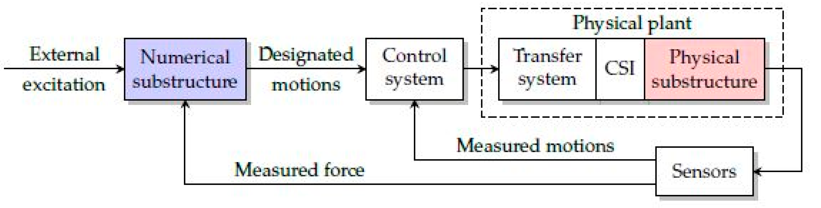
Real-Time Hybrid Simulation (RTHS) is an experimental testing method in which a structure is divided or substructured into a physical model of a part of the global structure and a numerical global structural model which are then connected in real time. Typically, the numerical substructure consists of components of the structure that can be modelled analytically with great confidence, whereas the physical substructures are those that have strong nonlinearities, uncertainties, or properties that cannot be modelled in closed form. The first RTHS test was carried out by Hakuno et al. [39] in which a cantilevered structure was excited by base excitations. As the real-time hybrid simulation considers both the physical and numerical model and exchanges their results accordingly, it provides more accurate results concerning the previously mentioned studies that did not apply RTHS in the methodology. Hybrid Simulation (HS) was initially presented in mechanical and aerospace engineering disciplines and is regarded as HIL or hardware-in-the-loop, which was used for decades for the purpose of designing machine components or control systems. However, with the advancement in science, the HS led to the introduction of pseudo-dynamic testing, which is also known as RTHS nowadays. There are various applications of real-time hybrid simulation in different fields of civil and structural engineering which include but are not limited to geotechnical Real-Time Hybrid Simulations (gRTHS), Real-Time Hybrid Simulation of Ocean Structures (RTHSO) and Real-Time Hybrid Optimisation (RTHO) [40]. The numerical substructure is modelled and the calculations from the physical substructure are fed back to the numerical model to calculate the associated motions which form the inner loop. On the other hand, the control system provides the command signals based on the calculated motions that are received and sends the command signal to the transfer system, which is followed by applying dynamic load to the physical model to make the physical substructure move along the desired motions, and this also forms the outer loop of the RTHS block diagram [41]. The below figure shows the flowchart of the conventional RTHS block diagram (see Figure 1).
4.1. Hybrid Fire Simulation
Hybrid Fire Simulation (HFS) attracted tremendous attention in recent decades, and there has only been limited research on combining physical testing and numerical modelling in fire engineering topics [33,34,35,36]. In the case of fire loads, the material’s characteristics at a high temperature could have a time-dependent behaviour.
The hybrid fire simulation was primarily addressed by Korzen et al. [42], in which an eight-storey steel frame building was considered as the case study. A column was tested with the gas furnace, and the rest of the structure was defined by a predefined idealised model as a constant axial stiffness. Through a six-channel control system in the laboratory, axial displacements and forces at the interface were exchanged.
By considering the necessity for improving the design of structures against fire or FFE discussed above, it is therefore, crucial to establish a more cost-conscious and efficient testing technique alternative to full-scale fire trials for a more thorough realisation of the performance of the complete structural systems exposed to fire.
Robert et al. [43,44] carried out an HFS on a single-storey concrete frame, in which the physical domain was a concrete slab that had degrees of freedom, whereas an elastic stiffness matrix addressed the numerical domain.
Mostafaei et al. in Ottawa, through hybrid fire simulation, experimented with a concrete column in a six-storey reinforced concrete structure in a gas furnace [45,46,47]. The study simulated the numerical domain as a 2D/3D finite element model in terms of a special purpose finite element software SAFIR. The attained axial deformations and forces at the interface of the numerical domain were exchanged with the physical time domain in each of the time steps.
The typical stages of hybrid fire simulation consist of the design of fire representation (fire simulation, parametric curve, and standard curve), and a second task, heat transfer analysis. The next stage of HFS is a nonlinear structural analysis.
4.2. Methodology
In the context of the hybrid fire simulation method, an essential requirement in capturing the structural behaviour is achieved by taking into account full interaction effects; that is to say the effects between the two subdomains, numerical and physical, including the heat transferred from the fire to the structures, heat conditions as well as the forces, displacements, and rotations induced by the elevated temperature. Moreover, it is also crucial to update the boundary conditions in the physical and numerical domains in real time during the HFS to fulfil full compatibility at the interface. The full interaction impacts can be realised by coupling the thermal analysis, mechanical analysis and thermal loading, and high-performance testing facilities. The details of the above-mentioned hybrid fire simulation are proposed to bring more insight into each of the analysis steps of the HFS.
The thermal analysis attempts to solve the temperature profile in the sections and structures subjected to fire, which consists of (1) the conductive heat transfer within and between the structural elements using finite element analysis; and (2) the convective and radiative heat transfer analysis from the fire to the surface of the structures by CFD commercial software.
During mechanical analysis coupled with thermal loading, normally by using specialised finite element software packages specially built for fire engineering, the structural response under the static and thermally induced mechanical loading is calculated. The mechanical analysis is carried out sequentially after the thermal analysis based on the previously generated temperature profile in the structure. In the mechanical structural analysis within the proposed framework, the building is exposed to the constant gravity load, the time-variant forces, the moments, and the temperature gradient defined by the physical domain at the interface node. The responses of the structure are computed in the thermal–mechanical analysis and are fed back to the physical specimen for the next cycle of HFS of the structure.
In order to take into account the full interactions for performance-based design, it is essential to have the possibility of sufficient data exchange and communication between the numerical and physical domains during the hybrid fire simulation. The implementation in the proposed framework is using the UT-SIM and OpenFresco interface platforms, which bring standard data exchange protocols. Nevertheless, both middleware platforms were originally developed for conducting seismic hybrid simulation for earthquakes, which only needs force and displacement information exchange between the numerical and physical domains. For implementing hybrid fire simulation, new thermal objects with the capacity to exchange temperature gradient information are being discussed at present.
Yu et al. [43] introduced a procedure of conducting hybrid fire simulation addressed in eight consecutive steps, in which the first step was to determine the fire scenario for the structure by implementing fire simulation in CFD code. Steps 2 and 3 will attain the initial and boundary conditions (structural deformations and forces) for the numerical and physical domain at the interface, considering the ambient temperature and gravity loads. Steps 4 to 8 elaborate on the hybrid fire simulation. Step 4 imposes the fire loading to the test specimen in the furnace, and afterwards, Step 5 controls the thermal and mechanical response in the interface node between the numerical and physical segments of the structure. The temperature gradient and the mechanical loads’ area are imposed in the numerical model in terms of an interface platform, and the thermomechanical analysis is performed afterwards to attain the global structural response. The local response is taken from the global one to be imposed on the physical specimen (step 7). The procedure from Steps 5 to 7 is then repeated until the end of the temperature–time history or the cooling process. The study further developed a methodology for RTHS for fire following earthquake scenarios. It takes into account the full interaction impact between the thermal and mechanical behaviour of the model. The numerical operations of this research work were carried out by OpenSEES as the finite element code to build the numerical model and OpenFRESCO as the middleware. The three main stages of the HFS (Hybrid Fire Simulation) include design fire curve definition, heat transfer analysis, and nonlinear structural analysis. The full interaction impacts are achieved by combining the thermal and mechanical analysis with thermal loading, testing equipment, and data exchange in the interface platform.
Considering the hybrid fire simulation method previously defined, Yu et al. [48] also introduced a developed version of the technique for fire following earthquake hybrid simulation. This update provides the evaluation of the effect of earthquake damage on active and passive fire protection systems or understanding of the impact of seismic damage on the fire resistance of the structure. Considering the cumulative damage concerning the earthquake in the structure is critical for applying the fire loading sequence.
In the physical test domain, the seismic damage in the test specimen can be attained using an experimental procedure. The main point is the test equipment could be combined to carry out the earthquake hybrid test first, and then, it is possible to impose the fire hybrid test; if two different facilities are used, besides the damage observed at the end of the earthquake tests, the boundary conditions (residual deformations and forces applied) require to be re-established. In terms of the numerical domain, the software for the thermomechanical analysis of the structure in fire requires taking into account the strain–stress and damage state and the damage to the structure after earthquake analysis.
5. FFE Probabilistic Fragility Analysis
The analysis of the buildings under fire loading is traditionally carried out by with standard fire curves (e.g., ISO 834), which may not represent a realistic fire effect on the structures. Such standard fire testing is limited to the single fire element, and consequently, it will not provide an understanding of the global behaviour of a structure towards fire loading. Therefore, in the context of FFE risk and cost analysis and assessment, fragility curves in fact describe the probability of a building damage associated with a specific damage state for a desired fire intensity measure. One of the essential features in fragility curve development is the quantified damage scale. In this regard, in a study conducted by Rush and Lange [49], a damage analysis was implemented where a column was exposed to a real travelling fire from the large scale on a full-scale four-story building. With regards to the fragility curves, four response measures (damage states) were considered which include: spalling, residual capacity, deflection, and peak rebar temperature. The fragility curves connected the intensity of fire to the probability within a certain damage state. The selected column from the full-scale model was equipped with 12 thermocouples, and the fire ignition was successfully implemented. The preliminary visual inspections of the columns indicated that the column did not suffer from substantial damages during the fire test. However, by using the fragility curves, it was possible to quantify the damage state and intensity of the column, and for this purpose, three different heights of the columns were selected to be investigated. It was noticed that the probability that the column was in damage state 4 (spalling) was about 40% in a 60 min duration. Moreover, for damage state 3 (residual capacity), the probability was defined as around 80%, and it was also 97% and 100% for the other two damage states, respectively.
6. Conclusion Remarks
The proposed review paper provides detailed insight into the recent breakthroughs in the post-earthquake fire impact on the damaged RC structures. A variety of research work has been conducted in terms of both numerical and experimental investigations, and their results have also been compared with each other for verification purposes. The results demonstrated that the loss of concrete cover is a very severe phenomenon in the PEF state, and it highly reduces the structural performance of the damaged member when it is exposed to heating.
Moreover, it was also observed that the residual capacity of the members is of utmost importance to analyse the behaviour of RC members: therefore, some of the proposed papers also conducted a third stage, in which the damaged structure was subjected again to simulated earthquake loading after the fire loading, and the results provide valuable information about the residual capacity of RC structures.
The experimental studies also suggest that the formation of plastic hinges in the damaged structures by PEF, which normally occurs in the beam–column joint area, can severely impact the performance of the RC structural members. In this regard, researchers recommended the relocation methods of plastic hinges by means of structural retrofitting by CFRP materials.
Despite the above-mentioned advancements in PEF, there are still research gaps in defining different aspects of fire effects on RC structures. There have been lesser studies of full-scale structures subjected to PEF concerning structural elements or materials, and as a result of this, limited information is available for full-scale multi-storey models. The complex nature of the concrete–rebar interface is also one of the other aspects that need to be taken into consideration in more detail. One other issue that is worthy of mentioning is that only limited studies have considered the long-term effects of concrete (i.e., creep and shrinkage) in their evaluations of PEF effects on RC structures.
This study suggests that a more detailed investigation of long-term effects should be considered in the process of sequential analysis stages. This will provide more realistic results and insights into the behaviour of damaged concrete structures that are exposed to fire loading. Moreover, one of the current research gaps is related to further understanding the mechanical and thermal effects on reinforced concrete elements which could potentially pave the way to gaining a better insight into the interactions between them under PEF scenarios, and it is strongly suggested that in such investigations, a sufficient number of mechanical and thermal degrees of freedom be considered in the physical and numerical domains of the structure. Additional research also needs to be carried out in hybrid fire simulation for PEF effects, as there is currently a limited number of research work in this area of study.
Author Contributions
Conceptualisatio, H.R.; methodology, H.R.; formal analysis, V.K.; investigation, V.K. and H.R.; writing—original draft preparation, V.K.; writing—review and editing, H.R.; supervision, H.R.; project administration, H.R. All authors have read and agreed to the published version of the manuscript.
Funding
This work was supported by the Foundation for Science and Technology (FCT)—Aveiro Research Centre for Risks and Sustainability in Construction (RISCO), University of Aveiro, Portugal (FCT/UIDB/ECI/04450/2020). This work was also supported by the Portuguese Foundation for Science and Technology (FCT) in the framework of project PTDC/ECI-EST/6534/2020 (HybridNET—Hybrid Simulation Integrated Facility for Real-Time, Multi-Hazard and Geographically-Distributed Testing).
Data Availability Statement
Data sharing not applicable.
Conflicts of Interest
The authors declare no conflict of interest.
References
- Vitorino, H.; Rodrigues, H.; Couto, C. Evaluation of post-earthquake fire capacity of reinforced concrete elements. Soil Dyn. Earthq. Eng. 2019, 128, 105900. [Google Scholar] [CrossRef]
- Juliá, P.B.; Ferreira, T.M.; Rodrigues, H. Post-earthquake fire risk assessment of historic urban areas: A scenario-based analysis applied to the Historic City Centre of Leiria, Portugal. Int. J. Disaster Risk Reduct. 2021, 60, 102287. [Google Scholar] [CrossRef]
- Shah, A.H.; Sharma, U.K.; Kamath, P.; Bhargava, P.; Reddy, G.R.; Singh, T. Fire performance of earthquake-damaged reinforced-concrete structures. Mater. Struct. 2015, 49, 2971–2989. [Google Scholar] [CrossRef]
- Wen, B.; Zhang, L.; Wu, B.; Niu, D. Structural Performance of Earthquake-damaged Beams in Fire. KSCE J. Civ. Eng. 2018, 22, 5009–5025. [Google Scholar] [CrossRef]
- Wu, B.; Xiong, W.; Wen, B. Thermal fields of cracked concrete members in fire. Fire Saf. J. 2014, 66, 15–24. [Google Scholar] [CrossRef]
- ISO 834-1; Fire Resistance Test—Elements of Building Construction, Part 1: General Requirements. International Organization for Standardization: Geneva, Switzerland, 1999.
- ASTM E119; Standard Methods of Fire Tests of Building Construction and Materials. ASTM International: Philadelphia, PA, USA, 1983.
- Vitorino, H.; Rodrigues, H.; Couto, C. Evaluation of post-earthquake fire capacity of a reinforced concrete one bay plane frame under ISO fire exposure. Structures 2020, 23, 602–611. [Google Scholar] [CrossRef]
- Wen, B.; Wu, B.; Niu, D. Post-earthquake fire performance of reinforced concrete columns. Struct. Infrastruct. Eng. 2015, 12, 1106–1126. [Google Scholar] [CrossRef]
- Li, L.-Z.; Liu, X.; Yu, J.-T.; Lu, Z.-D.; Su, M.-N.; Liao, J.-H.; Xia, M. Experimental study on seismic performance of post-fire reinforced concrete frames. Eng. Struct. 2019, 179, 161–173. [Google Scholar] [CrossRef]
- FEMA356; Prestandard and Commentary for the Seismic Rehabilitation of Buildings. Federal Emergency Management Agency: Washington, DC, USA, 2000.
- Chinthapalli, H.K.; Agarwal, A. Post-earthquake fire assessment of reinforced concrete columns. In Proceedings of the 11th International Conference on Structures in Fire, Risbane, Australia, 30 November–2 December 2020; pp. 230–241. [Google Scholar] [CrossRef]
- Behnam, B. Post-Earthquake Fire Analysis in Urban Structures: Risk Management Strategies; CRC Press: Boca Raton, FL, USA; Taylor & Francis Group: Abingdon, UK, 2017. [Google Scholar]
- Wen, B.; Zhang, L.; Wu, B.; Niu, D.; Wang, L.; Zhang, Y. Fire resistance of earthquake damaged reinforced concrete columns. Struct. Infrastruct. Eng. 2022, 18, 1–23. [Google Scholar] [CrossRef]
- Behnam, B.; Ronagh, H. Performance of reinforced concrete structures subjected to fire following earthquake. Eur. J. Environ. Civ. Eng. 2013, 17, 270–292. [Google Scholar] [CrossRef]
- Memari, M.; Mahmoud, H.; Ellingwood, B. Post-earthquake fire performance of moment resisting frames with reduced beam section connections. J. Constr. Steel Res. 2014, 103, 215–229. [Google Scholar] [CrossRef]
- Lie, T.T.; Celikkol, B. Method to Calculate the Fire Resistance of Circular Reinforced Concrete Columns. ACI Mater. J. 1991, 88, 84–91. [Google Scholar] [CrossRef]
- Wu, B.; Ma, Z.C. Damage analysis of R.C. structure under fires and low-cycle reciprocal load. J. Harbin Univ. Civ. Eng. Archit. 1997, 29, 7–12. [Google Scholar]
- Zhu, B.L.; Lu, Z.D.; Hu, K.X. The constitutive relation of concrete and steel under fires. Sichuan Build. Sci. 1990, 1, 37–43. [Google Scholar]
- Shah, A.H.; Sharma, U.K.; Kamath, P.; Bhargava, P.; Reddy, G.R.; Singh, T. Effect of Ductile Detailing on the Performance of a Reinforced Concrete Building Frame Subjected to Earthquake and Fire. J. Perform. Constr. Facil. 2016, 30, 04016035. [Google Scholar] [CrossRef]
- Shi, X.; Tan, T.-H.; Tan, K.-H.; Guo, Z. Effect of Force-Temperature Paths on Behaviors of Reinforced Concrete Flexural Members. J. Struct. Eng. 2002, 128, 365–373. [Google Scholar] [CrossRef]
- Sun, J.F.; Shi, X.D.; Guo, Z.H. The behaviors at elevating temperature and after cooling are investigated and compared for reinforced concrete beams. Archit. Struct. 2002, 32, 34–36. [Google Scholar]
- Chen, S.C.; Tian, X.M.; Yan, W.M. A preliminary survey on analysis method of building structures under post-earthquake fire. J. Civ. Archit. Environ. Eng. 2011, 33, 90–119. [Google Scholar]
- Miao, J.J.; Chen, N. Experimental research and numerical simulation on fire resistance performance of RC beams with damages caused by service loading. J. Build. Struct. 2013, 34, 1–11. [Google Scholar]
- Wu, B.; Ma, Z.C.; Ou, J.P. Study on the aseismic characteristics of RC compression-flexure members after fire. Earthq. Eng. Eng. Vib. 1994, 14, 24–34. [Google Scholar]
- Xiao, J.Z.; Xie, M. An experimental study on the seismic behavior of RC frame after fire. China Civ. Eng. J. 2005, 38, 36–44. [Google Scholar]
- Kodur, V.; Wang, T.; Cheng, F. Predicting the fire resistance behaviour of high strength concrete columns. Cem. Concr. Compos. 2004, 26, 141–153. [Google Scholar] [CrossRef]
- Kodur, V.K.R.; Cheng, F.-P.; Wang, T.-C.; Sultan, M.A. Effect of Strength and Fiber Reinforcement on Fire Resistance of High-Strength Concrete Columns. J. Struct. Eng. 2003, 129, 253–259. [Google Scholar] [CrossRef]
- Kodur, V.K.R. Spalling in High Strength Concrete Exposed to Fire: Concerns, Causes, Critical Parameters and Cures. In Advanced Technology in Structural Engineering; American Society of Civil Engineers: Reston, VA, USA, 2000; pp. 1–9. [Google Scholar] [CrossRef]
- Kodur, V.K.; Banerji, S.; Solhmirzaei, R. Test methods for characterizing concrete properties at elevated temperature. Fire Mater. 2019, 44, 381–395. [Google Scholar] [CrossRef]
- Banerji, S.; Gil, A.M.; Kodur, V. Application of structural health monitoring techniques for tracing fire-induced spalling in concrete structures. In Proceedings of the 11th International Conference on Structural Health Monitoring of Intelligent Infrastructure, Montreal, QC, Canada, 8–12 August 2022. [Google Scholar]
- Kamath, P.; Sharma, U.K.; Kumar, V.; Bhargava, P.; Usmani, A.; Singh, B.; Singh, Y.; Torero, J.; Gillie, M.; Pankaj, P. Full-scale fire test on an earthquake-damaged reinforced concrete frame. Fire Saf. J. 2015, 73, 1–19. [Google Scholar] [CrossRef]
- Imani, R.; Mosqueda, G.; Bruneau, M. Post-Earthquake Fire Resistance of Ductile Concrete Filled Double-Skin Tube Columns. In Proceedings of the NCEE 2014–10th U.S. National Conference on Earthquake Engineering: Frontiers of Earthquake Engineering, Anchorage, AK, USA, 21–25 July 2014. [Google Scholar] [CrossRef]
- Meacham, B.J. Post-Earthquake Fire Performance of Buildings: Summary of a Large-Scale Experiment and Conceptual Framework for Integrated Performance-Based Seismic and Fire Design. Fire Technol. 2015, 52, 1133–1157. [Google Scholar] [CrossRef]
- Shah, A.H.; Sharma, U.; Bhargava, P. Outcomes of a major research on full scale testing of RC frames in post earthquake fire. Constr. Build. Mater. 2017, 155, 1224–1241. [Google Scholar] [CrossRef]
- Behnam, B.; Lim, P.J.; Ronagh, H.R. Plastic Hinge Relocation in Reinforced Concrete Frames as a Method of Improving Post-earthquake Fire Resistance. Structures 2015, 2, 21–31. [Google Scholar] [CrossRef]
- Behnam, B.; Ronagh, H.R.; Lim, P.J. Numerical evaluation of the post-earthquake fire resistance of CFRP-strengthened reinforced concrete joints based on experimental observations. Eur. J. Environ. Civ. Eng. 2015, 20, 142–160. [Google Scholar] [CrossRef]
- Behnam, B. Effects of thermal spalling on the fire resistance of earthquake-damaged reinforced concrete structures. Eur. J. Environ. Civ. Eng. 2019, 26, 761–778. [Google Scholar] [CrossRef]
- Hakuno, M.; Shidawara, M.; Hara, T. Dynamic destructive test of a cantilever beam, controlled by an analog-computer. Proc. Jpn. Soc. Civ. Eng. 1969, 1969, 1–9. [Google Scholar] [CrossRef] [PubMed]
- Palacio-Betancur, A.; Soto, M.G. Recent Advances in Computational Methodologies for Real-Time Hybrid Simulation of Engineering Structures. Arch. Comput. Methods Eng. 2022, 30, 1637–1662. [Google Scholar] [CrossRef]
- Li, H.-W.; Wang, F.; Ni, Y.-Q.; Wang, Y.-W.; Xu, Z.-D. An Adaptive and Robust Control Strategy for Real-Time Hybrid Simulation. Sensors 2022, 22, 6569. [Google Scholar] [CrossRef] [PubMed]
- Korzen, M.; Magonette, G.; Buchet, P. Mechanical Loading of Columns in Fire Tests by Means of the Substructuring Method. In Annual Meeting, Gesellschaft fur Angewandte Mathematik und Mechanik: GAMM 98; Wiley: Weinheim, Germany, 1999. [Google Scholar]
- Robert, F.; Rimlinger, S.; Collignon, C. Promethee, Fire Resistance Facility Taking into Account the Surrounding Structure. In Proceedings of the 1st International Workshop on Concrete Spalling Due to Fire Exposure, Leipzig, Germany; 2009. [Google Scholar]
- Robert, F.; Rimlinger, S.; Collignon, C. Structure fire resistance: A joint approach between modelling and full scale testing (substructuring system). In Proceedings of the 3rd International fib Congress incorporating the PCI Annual Convention and Bridge Conference 2010, Washington, DC, USA, 29 May–2 June 2010. [Google Scholar]
- Mostafaei, H. Hybrid fire testing for assessing performance of structures in fire—Methodology. Fire Saf. J. 2013, 58, 170–179. [Google Scholar] [CrossRef]
- Mostafaei, H. Hybrid fire testing for assessing performance of structures in fire—Application. Fire Saf. J. 2013, 56, 30–38. [Google Scholar] [CrossRef]
- Mostafaei, H.; Kabeyasawam, T. Performance of a six-story reinforced concrete structure in post-earthquake fire. In Proceedings of the 9th U.S. National and 10th Canadian Conference on Earthquake Engineering, Toronto, ON, Canada, 25–29 July 2010. [Google Scholar]
- Yu, Z.; Lau, D.; Erochko, J.; Kwon, O.-S.; Kashef, A. Methodology for Fire Following Earthquake Hybrid Simulation. In Proceedings of the 12th Canadian Conference on Earthquake Engineering, Quebec, QC, Canada, 17 June 2019; pp. 1–8. [Google Scholar]
- Rush, D.; Lange, D. Towards a fragility assessment of a concrete column exposed to a real fire–Tisova Fire Test. Eng. Struct. 2017, 150, 537–549. [Google Scholar] [CrossRef]
Figure 1.
RTHS block diagram [41].
Figure 1.
RTHS block diagram [41].

Disclaimer/Publisher’s Note: The statements, opinions and data contained in all publications are solely those of the individual author(s) and contributor(s) and not of MDPI and/or the editor(s). MDPI and/or the editor(s) disclaim responsibility for any injury to people or property resulting from any ideas, methods, instructions or products referred to in the content. |
© 2023 by the authors. Licensee MDPI, Basel, Switzerland. This article is an open access article distributed under the terms and conditions of the Creative Commons Attribution (CC BY) license (https://creativecommons.org/licenses/by/4.0/).
Share and Cite
MDPI and ACS Style
Khiali, V.; Rodrigues, H. Experimental Evaluation of Post-Earthquake Fire on Reinforced Concrete Structures—A Review. CivilEng 2023, 4, 469-482. https://doi.org/10.3390/civileng4020027
AMA Style
Khiali V, Rodrigues H. Experimental Evaluation of Post-Earthquake Fire on Reinforced Concrete Structures—A Review. CivilEng. 2023; 4(2):469-482. https://doi.org/10.3390/civileng4020027
Chicago/Turabian StyleKhiali, Vahid, and Hugo Rodrigues. 2023. "Experimental Evaluation of Post-Earthquake Fire on Reinforced Concrete Structures—A Review" CivilEng 4, no. 2: 469-482. https://doi.org/10.3390/civileng4020027