
Review of Accelerated Bridge Construction Systems for Bridge Superstructures and Their Adaptability for Cold Weather


Abstract
:1. Introduction
2. General Synopsis of Elements and Systems Used for ABC Projects around the World
2.1. Accelerated Bridge Construction (ABC)
2.1.1. What Is ABC?
2.1.2. Why ABC?
2.2. Prefabricated/Precast Bridge Elements and Systems (PBES)
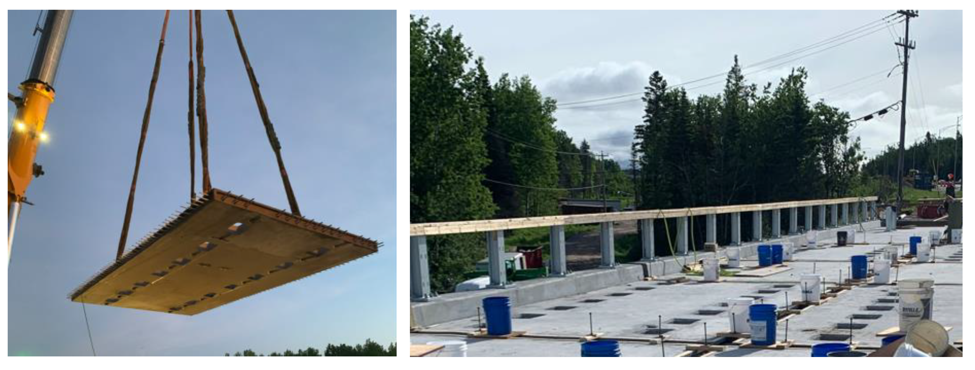
2.2.1. Deck Elements
- Stay-in-place deck forming
- Steel Form
- Prestressed/reinforced concrete form
- 2.
- Full-depth deck panels
- Prestressed/Reinforced Concrete Panel
- Metallic materials (steel and aluminum)
- Timber
- Fiber-reinforced polymer
2.2.2. Girders
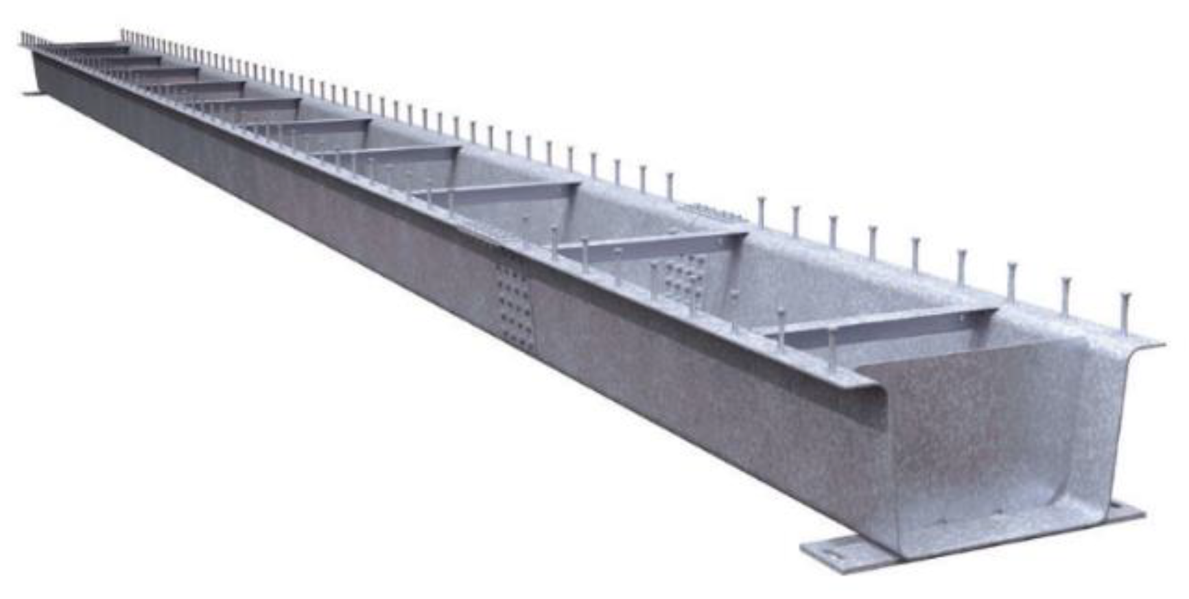
- Steel girders
- 2.
- Prestressed/Reinforced Concrete Girders
- Precast concrete (PC) I-girders
- Precast spread box girders
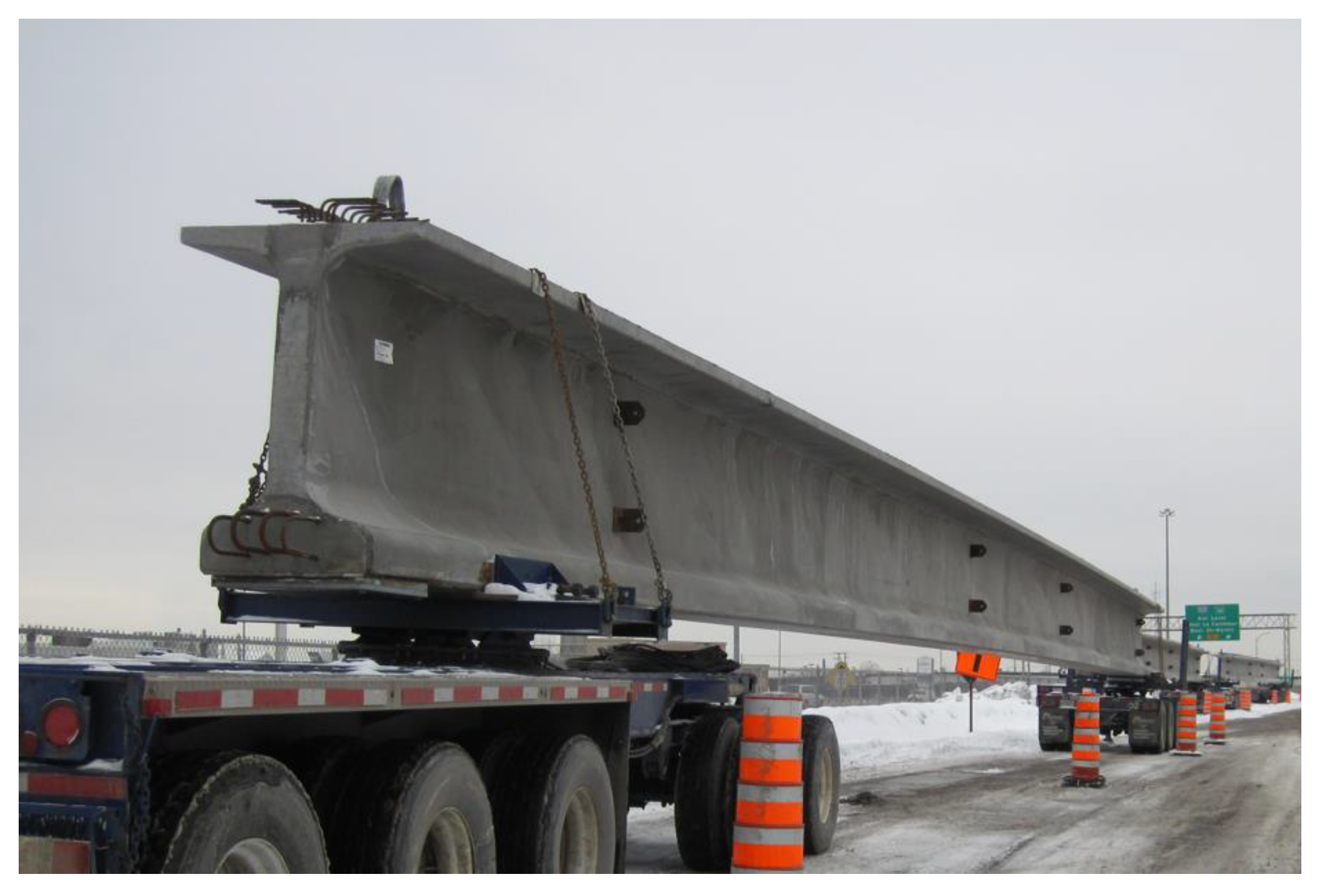
- Precast bulb-tee girders (or New England Bulb Tee girders, NEBT)
- Precast NU-I girders (University of Nebraska girders)
2.2.3. Modular Systems
- Metallic systems
- Topped multi-beam unit
- Orthotropic systems
- Modular folded plate girder system
- 2.
- Modular precast concrete systems
- Inverted-T precast slab
- Precast Adjacent Box Girders
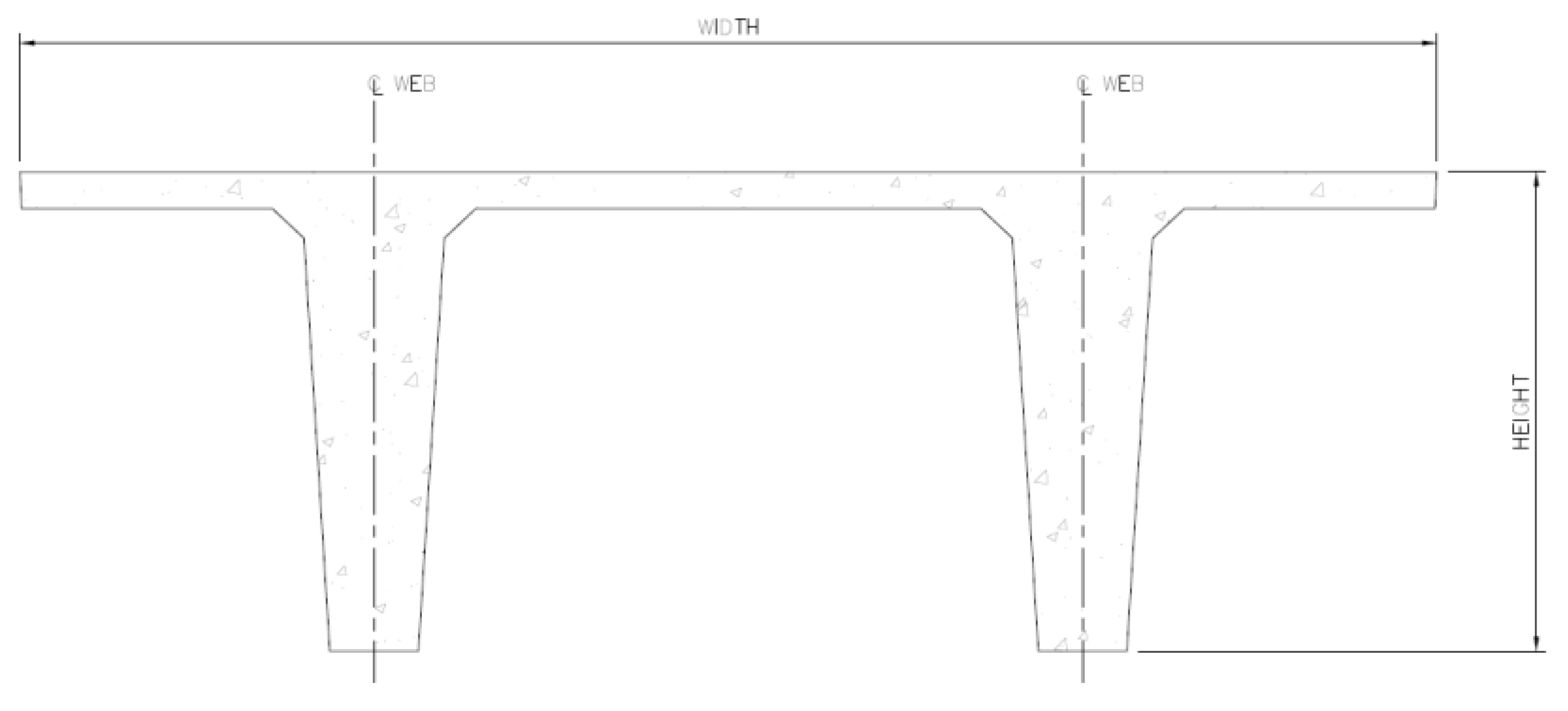
- Double-Tee Girder
- Northeast Extreme Tee (NEXT) Beam
- Decked Bulb-Tee Girder
- Precast Segmental Box Girder
- Pi-Girder
- 3.
- Mixed steel–concrete systems
- Precast modified beam-in-slab
- INVERSET™ system
- Decked Steel Girder System
- 4.
- FRP girder system
- 5.
- Timber systems
- Laminated deck span system
- Laminated girder deck system
2.2.4. Barriers
2.3. Most Commonly Used PBES in Short- and Medium-Span Bridges
3. General Synopsis of Connection Joints
3.1. Closure Joints
- Post-tensioned connections
- 2.
- Mechanical Connections
- 3.
- Ultra-High-Performance Concrete Connections
- 4.
- Connections using normal-strength concrete
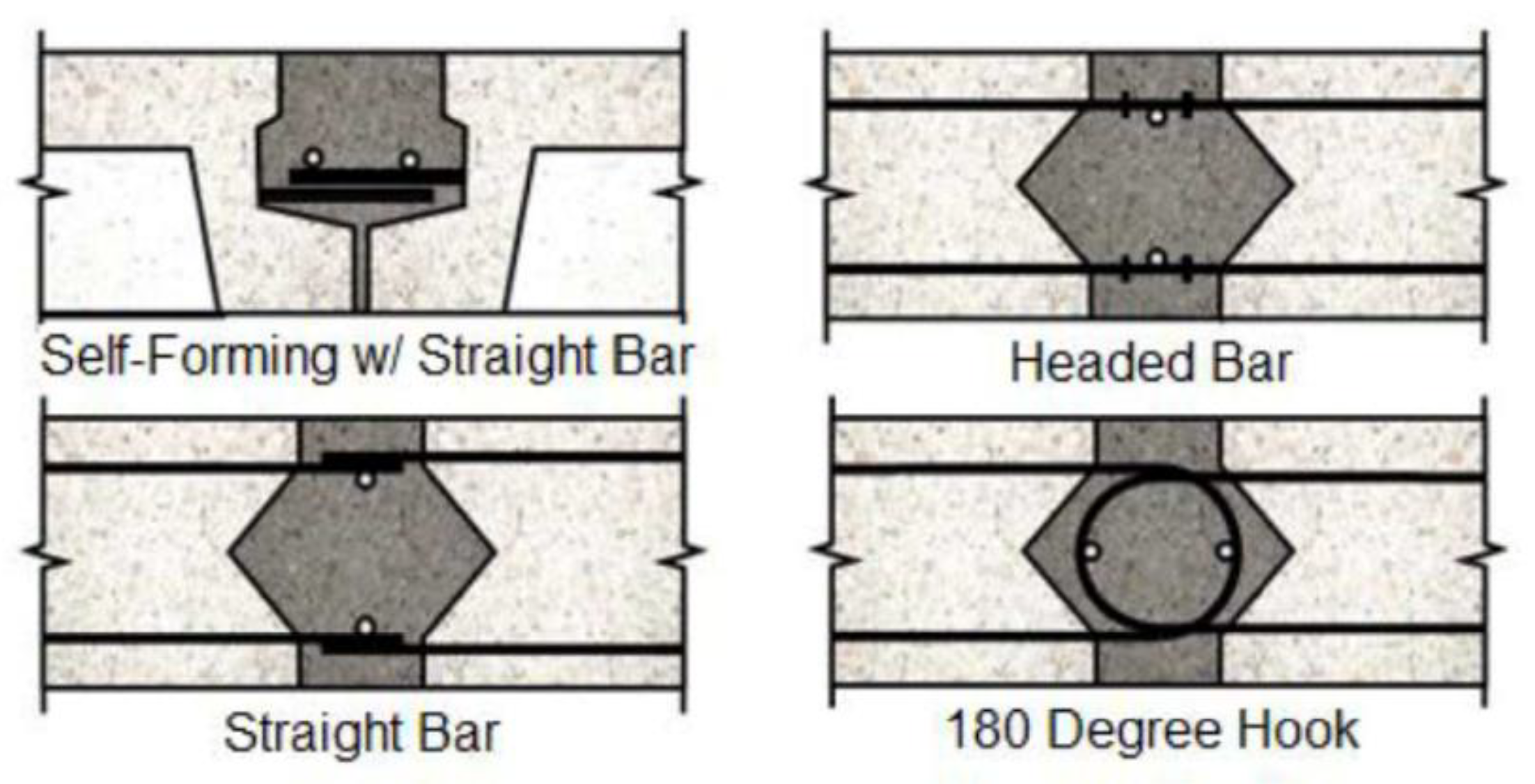
- The headed bar is used to connect precast deck modules. The use of 15 M headed rebar bases provides a satisfactory structural performance for narrow closure joints. The main issue of this type of connection is the enlarged size of the head at the end, which reduces the concrete cover at that location [43];
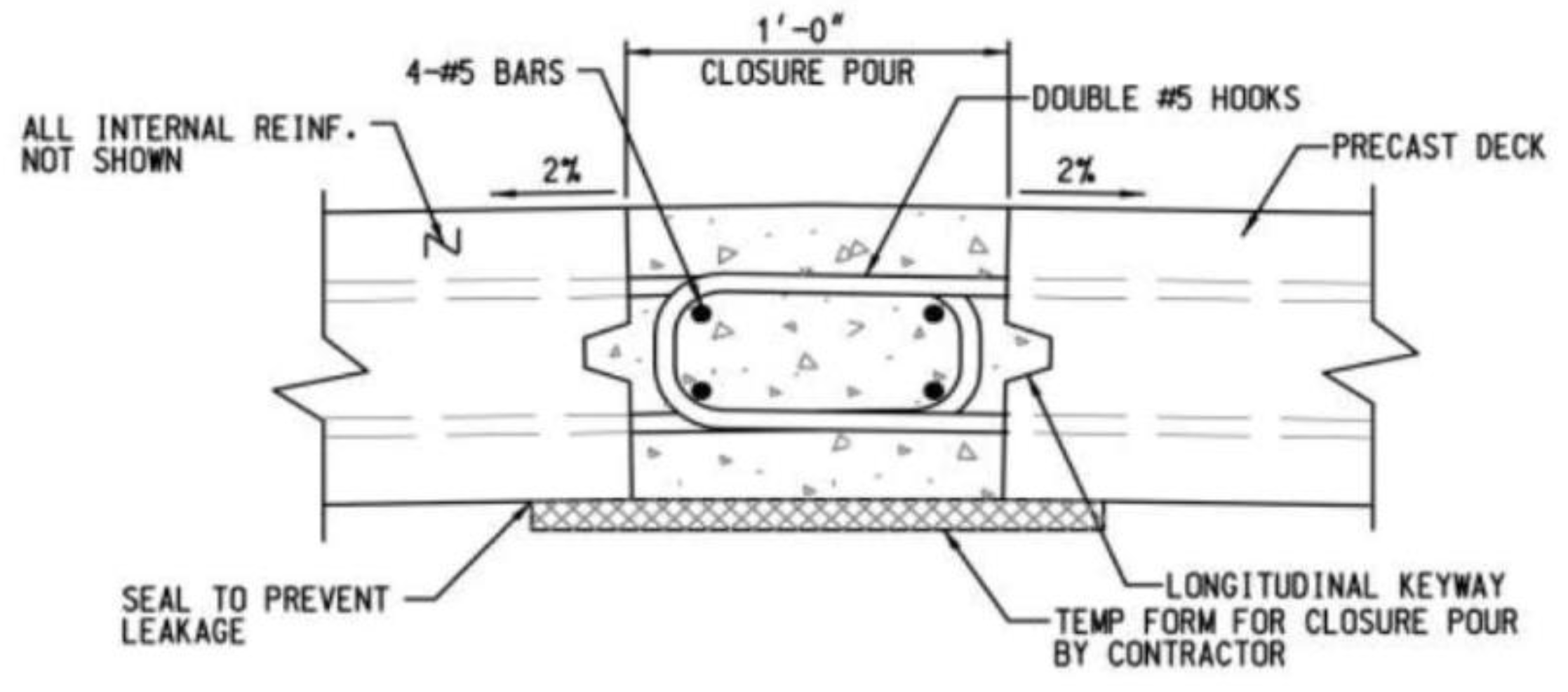
- The 180-degree hooked bar (or full hook), as shown in Figure 12, is employed to offer a remedy for the issue that headed bars present [43]. Generally, it makes sense to use this type of joint in the longitudinal direction [7]. For the United States, the AASHTO LRFD Specifications indicate a bend diameter that results in a deck thickness greater than 240 mm, yet the deck thickness is typically less than 215 mm, and, therefore, the use of full hooked bars will result in an increase in the deck thickness [43]. The hooked bar detail has a very good construction speed and durability and is easily accessible for inspection [34];
- A straight bar (or straight reinforcement) is one of the most common methods of joining precast decks, despite the fact that straight bars require wider closure joints for the development of bar tension [43]. Thus, it is best used in the longitudinal direction, where the joint between panels follows the line of the beam [7]. The straight bar detail has very good durability and is easily accessible for inspection [34];
- Spiral reinforcement consists of winding the straight bars of adjacent slabs with spiral reinforcement in the closure joint. This method of reinforcement is rarely used because its construction is difficult [43].
- 5.
- Performance
3.2. Shear Keys
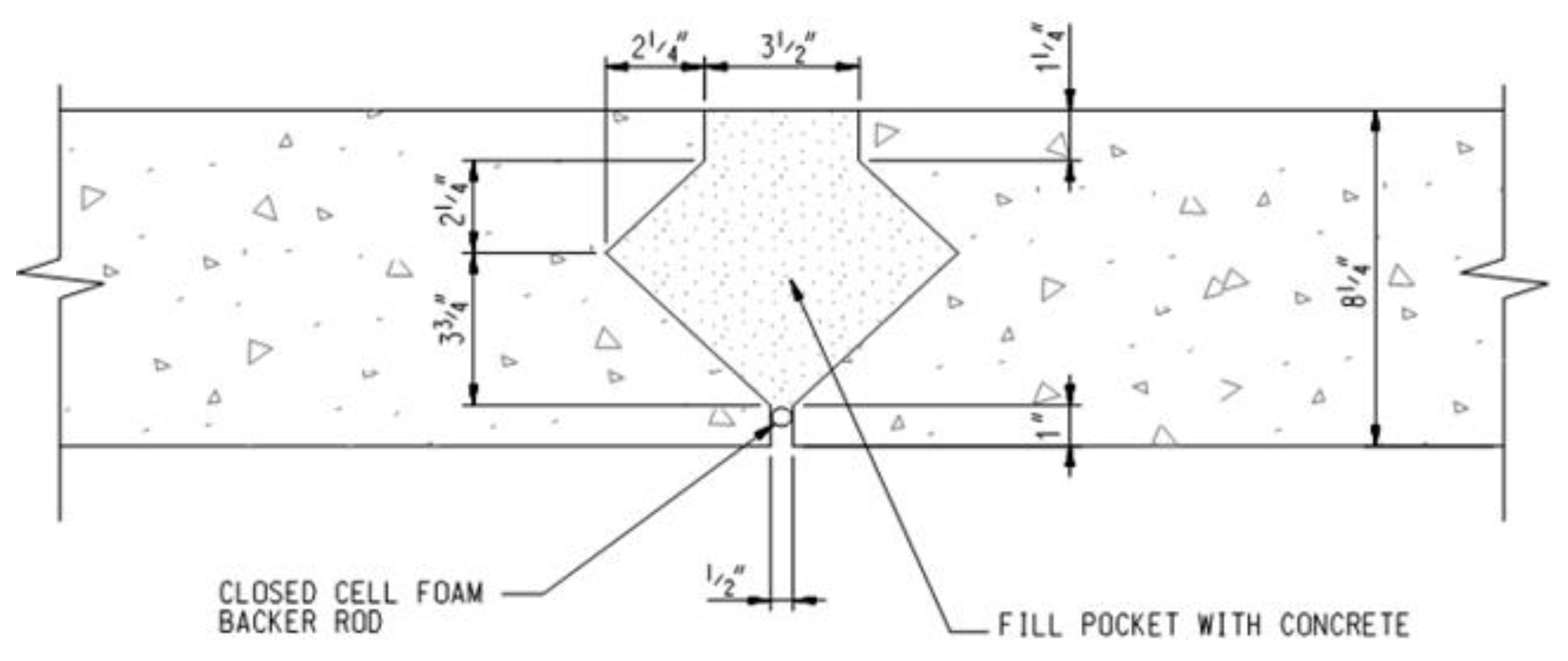
- Diamond or rectangular shear key
- 2.
- Straight Shear Key
- 3.
- U-Shaped Shear Key
- 4.
- V-Shaped Shear Key
3.3. PBES Connections
- Full-depth deck panels
- 2.
- Girders with an integral deck
3.4. Materials Used in Conjunction with PBESs
3.4.1. Ultra-High-Performance Concrete
3.4.2. Cementitious Grouts
3.5. Adaptability of ABC to Cold Weather
4. Canadian Experience in PBESs, Materials and Products
4.1. PBESs Already Used in Canada
4.2. Materials and Products Suitable for Use in Cold Weather Regions
- Hardening accelerator
- 2.
- Flowable cementitious grout
- 3.
- Grout/Mortar/Anchoring System
- A mortar can be used as a low-temperature, rapid curing, vinyl ester grout/mortar and injection resin for repairing concrete or for grouting base plates and various types of anchoring. Its application temperature can be down to −40 °C, and it cures down to −20 °C [64].
- A convenient, low-temperature modified-methacrylate structural repair mortar/grouting system can be used for repairing concrete, grouting base plates and patching roadways, bridge decks and floors. Its application temperature can be down to −10 °C or −25 °C with an additive [64].
- 4.
- Anchoring Gel
- 5.
- Structural Adhesive
5. Performance and Sustainability of the PBESs
- i.
- The average deterioration rate for bridges with FDPC deck panels was found to be slightly higher than that for bridges with CIP decks (−0.12 compared to −0.09). This leads to a slightly longer estimated service life for bridges with CIP decks, which was found to be 35 years compared to 33 years for bridges with FDPC deck panels.
- ii.
- The deterioration rates for bridges with different types of transverse and longitudinal joints are presented. Although these values are highly scattered, we can observe that transverse mechanical welded joints, the UHPC with 180 °C hooks and the conventional concrete joints with 180 °C hooks perform the worst. They have a deterioration rate of −0.13, −0.40 and −0.17, respectively, with an estimated service life of less than 30 years. The small number of bridges per type of joint and the relatively recent construction for most of them do not allow to draw recommendations from this study about which joints have the best performance.
- iii.
- The deterioration rate for bridges with FDPC deck panels in very cold weather regions was found to be higher than that for bridges with CIP decks in the same regions (−0.08 compared to −0.05). This leads to a shorter estimated service life for bridges with FDPC deck panels, which was found to be 35 years compared to 38 years for bridges with CIP decks. Both FDPC and CIP decks showed the same deterioration rate in the cold weather regions, which was −0.09 along the period of inspections; however, the estimated service life for FDPC decks was found to be 33 years compared to 35 years for CIP decks in cold regions.
- iv.
- The deterioration rate is increasing for FDPC deck panels with a high volume of traffic compared to CIP decks. For an Average Debit Truck Traffic (ADTT) of more than 6000, the deterioration rate of FDPC deck panels is −0.16 compared to −0.09 for CIP decks. This leads to an estimated service life of 28 years for FDPC deck panels compared to one of 34 years for CIP decks.
- v.
- Other factors, such as the type of wearing surface and the main span material, are also found to influence the performance of FDPC deck panels. However, there is no influence found for the construction type regarding the performance of FDPC deck panels; new construction and rehabilitation projects showed the same deterioration rate and the same estimated service life.
6. Conclusions
Author Contributions
Funding
Data Availability Statement
Conflicts of Interest
References
- Éditions Eyrolles. Available online: https://www.editions-eyrolles.com/Dico-BTP/definition.html?id=7196 (accessed on 4 October 2022).
- Hassan, M.; École de Technologie Supérieure, Montréal, Québec, Canada. Personal communication, 2021.
- U.S. Department of Transportation Federal Highway Administration. Available online: https://www.fhwa.dot.gov/bridge/abc/ (accessed on 4 October 2022).
- Hällmark, R.; White, H.; Collin, P. Prefabricated bridge construction across Europe and America. Pract. Period. Struct. Des. Constr. 2012, 17, 82–92. [Google Scholar] [CrossRef]
- Culmo, M.P.; Lord, B.; Huie, M.; Beerman, B. Accelerated Bridge Construction: Experience in Design, Fabrication and Erection of Prefabricated Bridge Elements and Systems: Final Manual; United States, Federal Highway Administration, Office of Bridge Technology: Washington, DC, USA, 2011.
- Culmo, M.P.; Marsh, L.; Stanton, J. Recommended AASHTO Guide Specifications for ABC Design and Construction, 1st ed.; The National Academies Press: Washington, DC, USA, 2018. [Google Scholar]
- Shahrokhinasab, E.; Garber, D. ABC-UTC Guide for: Full-Depth Precast Concrete (FDPC) Deck Panels (May 2019), ABC-UTC. Available online: https://abc-utc.fiu.edu/wp-content/uploads/sites/52/2019/05/ABC-UTC-Guide-to-FDPC-Deck-Panels.pdf (accessed on 16 January 2023).
- Ghasemi, S.; Mirmiran, A.; Xiao, Y.; Mackie, K. Novel UHPC-CFRP waffle deck panel system for accelerated bridge construction. J. Compos. Constr. 2016, 20, 04015042. [Google Scholar] [CrossRef]
- Chung, P.; Wolfe, R.; Ostrom, T.; Hida, S. Accelerated Bridge construction applications in California—A lessons learned report (August 2008). Caltrans CADOT. Available online: https://dokumen.tips/documents/accelerated-bridge-construction-applications-in-i-caltrans-engineering-services.html?page=1 (accessed on 16 January 2023).
- Richardson, M.W.; Scott, D.L.; Tremblay, J.A. Concrete Bridges in New Hampshire. ASPIRE 2009, 9, 48–50. [Google Scholar]
- Bardow, A.K.; Seraderian, R.L.; Culmo, M.P. Design, fabrication and construction of the New England Bulb-Tee girder. PCI J. 1997, 42, 30–40. [Google Scholar] [CrossRef]
- Optimized Sections for High-Strength Concrete Bridge Girders–Effect of Deck Concrete Strength. (October 2006), U.S. Department of Transportation Federal Highway Administration. Available online: https://www.fhwa.dot.gov/publications/research/infrastructure/structures/05058/05058.pdf (accessed on 16 January 2023).
- Abudayyeh, O. A Sensor Network System for the Health Monitoring of the Parkview Bridge Deck; Michigan, Dept. of Transportation: Lansing, MI, USA, 2010.
- MDOT-BDM. Michigan Bridge Design Manual (BDM), 5th ed.; Michigan Department of Transportation (MDOT): Lansing, MI, USA, 2011.
- Attanayake, U.; Abudayyeh, O.; Cooper, J.; Mohammed, A.W.; Aktan, H. First full-depth deck-panel accelerated bridge construction project in Michigan: Constructability challenges and lessons learned. J. Perform. Constr. Facil. 2014, 28, 128–135. [Google Scholar] [CrossRef]
- Lavallee, R.; Cadman, K. New England Bulb Tee girder brings strength, elegance and economy to Jetport Interchange Bridge. PCI J. 2001, 46, 68–75. [Google Scholar] [CrossRef]
- Fouad, F.H.; Rizk, T.; Stafford, E.L.; Hamby, D. A Prefabricated Precast Concrete Bridge System for the State of Alabama; University Transportation Center for Alabama: Tuscaloosa, AL, USA, 2006. [Google Scholar]
- Geren, K.L.; Tadros, M.K. The NU precast/prestressed concrete bridge I-girder series. PCI J. 1994, 39, 26–39. [Google Scholar] [CrossRef]
- Beacham, M.; Derrick, D. Longer Bridge spans with Nebraska’s NU I-girders. TR News 1999, 203, 42–43. [Google Scholar]
- Hanna, K.; Morcous, G.; Tadros, M.K. Design Aids of NU I-Grinder Bridges. Neb. Dep. Transp. Res. Rep. 2010, 64, 1–439. [Google Scholar]
- Morcous, G.; Hanna, K.; Tadros, M.K. Impact of 0.7-inch diameter strands on NU I-girders. Neb. Dep. Transp. Res. Rep. 2011, 88, 1–204. [Google Scholar]
- Valmont Structures. Available online: https://az276020.vo.msecnd.net/valmontproduction/docs/librariesprovider97/bridge---technical-docs/valmont-bridge-u-beam-specification-guide-and-catalog-_-valmont-bridge-systems.pdf?sfvrsn=c49eaa39_2 (accessed on 3 December 2022).
- Bell, C.M.; French, C.E.; Shield, C.K. Application of precast decks and other elements to bridge structures. Minn. Dep. Transp. Res. Rep. 2006, 37, 1–271. [Google Scholar]
- French, C.; Shield, C.; Klaseus, D.; Smith, M.; Eriksson, W.; Ma, Z.; Zhu, P.; Lewis, S.; Chapman, C.E. Cast-in-Place Concrete Connections for Precast Deck Systems; NCHRP Project 10-71; Transportation Research Board: Washington, WA, USA, 2011. [Google Scholar]
- Culmo, M.P.; Seraderian, R.L. Development of the northeast extreme tee (NEXT) beam for accelerated bridge construction. PCI J. 2010, 55, 86–101. [Google Scholar] [CrossRef]
- Badie, S.S.; Kamel, M.R.; Tadros, M.K. Precast pretensioned trapezoidal box beam for short span bridges. PCI J. 1999, 44, 48–59. [Google Scholar] [CrossRef]
- PCI Committee. Fabrication and shipment cracks in prestressed hollow-core slabs and double-tees. PCI J. 1983, 28, 1–24. [Google Scholar]
- Li, L.; Ma, Z.; Griffey, M.E.; Oesterle, R.G. Improved longitudinal joint details in decked bulb tees for accelerated bridge construction: Concept development. J. Bridge Eng. 2010, 15, 327–336. [Google Scholar] [CrossRef]
- Culmo, M.P.; Seraderian, R. Guidelines for Accelerated Bridge Construction Using Precast/Prestressed Concrete Elements Including Guideline Details, 2nd ed.; Precast/Prestressed Concrete Institute Northeast (PCINE): Chicago, IL, USA, 2014. [Google Scholar]
- Freyermuth, C.L. AASHTO-PCI-ASBI Segmental Box Girder Standards: A new product for grade separations and interchange bridges. PCI J. 1997, 42, 32–42. [Google Scholar] [CrossRef] [Green Version]
- Graybeal, B.A. Structural Behaviour of a 2nd Generation Ultra-High Performance Concrete Pi-Girder; United States, Federal Highway Administration, Office of Infrastructure Research and Development: Washington, DC, USA, 2009.
- Rouse, J.; Wipf, T.J.; Phares, B.; Fanous, F.; Berg, O. Design, Construction, and Field-Testing of an Ultra High Performance Concrete Pi-Girder Bridge; Iowa State University, Institute for Transportation: Ames, IA, USA, 2011. [Google Scholar]
- Klaiber, W.; Wipf, T.; Wineland, V. Precast Concrete Elements for Accelerated Bridge Construction: Laboratory Testing, Field-Testing, and Evaluation of a Precast Concrete Bridge, Black Hawk County; Iowa State University, Center for Transportation Research and Education: Ames, IA, USA, 2009. [Google Scholar]
- Culmo, M.P. Connection Details for Prefabricated Bridge Elements and Systems; United States, Federal Highway Administration, Office of Bridge Technology: Washington, DC, USA, 2009.
- Versace, J.; Ramirez, J.A. Implementation of Full-Width Precast Bridge Deck Panels: A Synthesis Study. Purdue Univ. West Lafayette Indiana 2004. [Google Scholar] [CrossRef] [Green Version]
- LaViolette, M.D.; Evans, D.; Nelson, J.; Sivakumar, B. ABC Modular Bridge Demonstration Project Design and Construction. In Proceedings of the Precast/Prestressed Concrete Institute 57th Annual Convention and National Bridge Conference, Salt Lake City, UT, USA, 22–26 October 2011. [Google Scholar]
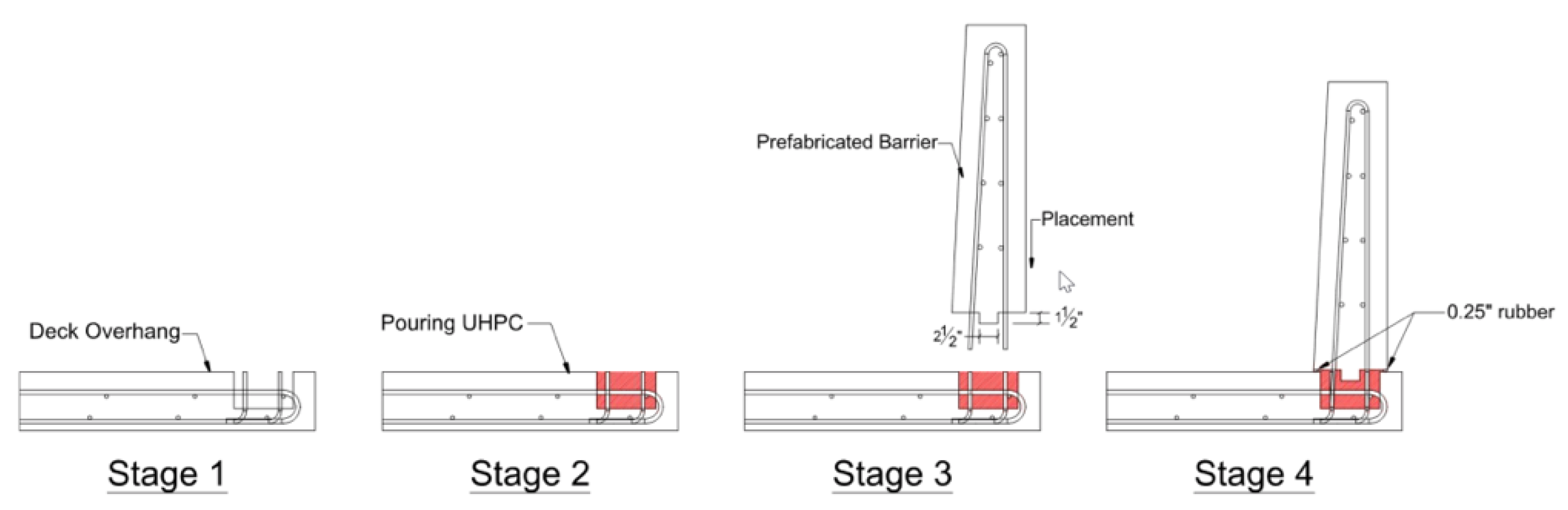
- Azizinamini, A.; Mantawy, I.M.; Anwer, M.A. Use of All Lightweight Concrete in Conjunction with UHPC Connection for Prefabricated Barrier System. In Proceedings of the 2022 ABC-UTC Research Day 1, Miami, FL, USA, 7 April 2022. [Google Scholar]
- Aktan, H.; Attanayake, U. Improving Bridges with Prefabricated Precast Concrete Systems; Michigan, Dept. of Transportation, Office of Research Administration: Lansing, MI, USA, 2013.
- Canadian Precast/Prestressed Concrete Institute. Available online: https://www.cpci.ca/en/about_us/project_month/march_2018/ (accessed on 4 October 2022).
- Moran, J. The Fast 14 project. Public Roads 2012, 75, 18–23. [Google Scholar]
- Culmo, M.P.; Halling, M.W.; Maguire, M.; Mertz, D. Recommended Guidelines for Prefabricated Bridge Elements and Systems Tolerances and Recommended Guidelines for Dynamic Effects for Bridge Systems; NCHRP Project 12-98; Transportation Research Board: Washington, WA, USA, 2017. [Google Scholar]
- American Association of State Highway and Transportation Officials (AASHTO). LRFD Guide Specifications for Accelerated Bridge Construction, 1st ed.; AASHTO: Washington, DC, USA, 2018. [Google Scholar]
- Jahromi, A.J.; Mantawy, I.M.; Azizinamini, A. ABC-UTC Guide for: Service Life Design of Longitudinal Deck Closure Joints (May 2019), ABC-UTC. Available online: https://abc-utc.fiu.edu/wp-content/uploads/sites/52/2019/06/Guide-for-Longitudinal-Closure-Joints-Full-V6-Final.pdf (accessed on 16 January 2023).
- Russell, H.G.; Graybeal, B.A.; Russell, H.G. Ultra-High Performance Concrete: A State-of-the-Art Report for the Bridge Community; United States, Federal Highway Administration, Office of Infrastructure Research and Development: McLean, VA, USA, 2013.
- Zhou, Z.; Qiao, P. Durability of ultra-high-performance concrete in tension under cold weather conditions. Cem. Concr. Compos. 2018, 94, 94–106. [Google Scholar] [CrossRef]
- Yuan, J.; Graybeal, B.A. Bond Behaviour of Reinforcing Steel in Ultra-High Performance Concrete; United States, Federal Highway Administration, Office of Infrastructure Research and Development: McLean, VA, USA, 2014.
- Laldji, S.; École de Technologie Supérieure, Montréal, Québec, Canada. Personal communication, 2022.
- Lamothe, S.; (École de Technologie Supérieure, Montréal, Québec, Canada). Personal communication, 2022.
- Pigeon, M. La durabilité au gel du béton. Mater. Struct. 1989, 22, 3–14. [Google Scholar] [CrossRef]
- ACI Committee 306. Guide to Cold Weather Concreting, 1st ed.; American Concrete Institute: Farmington Hills, MI, USA, 2016. [Google Scholar]
- Korhonen, C. New developments in cold-weather concreting. In Cold Regions Engineering: Cold Regions Impacts on Transportation and Infrastructure; American Society of Civil Engineers Library: Reston, VA, USA, 2002; pp. 531–537. [Google Scholar]
- Nmai, C.K. Cold weather concreting admixtures. Cem. Concr. Compos. 1998, 20, 121–128. [Google Scholar] [CrossRef]
- Mamillan, M. Une analyse des rapports généraux présentés au Colloque international de la RILEM, Moscou, 14–16 octobre 1975. Matériaux Et Constr. 1976, 9, 129–140. [Google Scholar] [CrossRef]
- Fowler, J.R.; Eng, P. Accelerated Bridge construction. In Proceedings of the Annual Conf. & Exhibition of the Transportation Association of Canada, Charlottetown, PE, Canada, 17–20 September 2006; pp. 1–21. [Google Scholar]
- The ACEC-BC Awards. Available online: https://acecbcawards.com/2022-awards/2022-transportation-bridges/mosquito-creek-bridge-replacement/ (accessed on 4 October 2022).
- Mills, D.; Chow, K.T.; Marshall, S.L. Design-Construction of Esker Overhead. PCI J. 1991, 36, 44–51. [Google Scholar] [CrossRef]
- Technical Services Branch Alberta Transportation. Alberta Transportation NU Girder Bridge Design and Detailing Manual, 1st ed.; Alberta Department of Transportation: Valleyview, AB, Canada, 2018. [Google Scholar]
- Canadian Precast/Prestressed Concrete Institute. Available online: https://www.cpci.ca/en/about_us/project_month/april_2002/ (accessed on 4 October 2022).
- Daviau-Desnoyers, D.; Hassan, M. Design and construction of Boychuk Interchange. In Proceedings of the 10th International Conference on Short and Medium Span Bridges, Québec, QC, Canada, 31 July–3 August 2018. [Google Scholar]
- Marosi, M.; Hassan, M. Design and Construction of the Boychuck and McOrmond Interchanges. In Proceedings of the Annual Conference of the Canadian Society for Civil Engineering, CSCE, Saskatoon, SK, Canada, 27–30 May 2020. [Google Scholar]
- Canadian Precast/Prestressed Concrete Institute. Available online: https://www.cpci.ca/en/about_us/project_month/april_2006/ (accessed on 4 October 2022).
- Nader, M. Accelerated Bridge construction of the new Samuel De Champlain Bridge. J. Bridge Eng. 2020, 25, 05019015. [Google Scholar] [CrossRef]
- Carlin, G.; Beaudoin, P.; Mailhot, G.; Cap, R. Jacques Cartier Bridge Re-Decking Project—An Owner’s Perspective. In Proceedings of the Transportation: From Vision to Reality. Annual Conference and Exhibition of the Transportation Association of Canada (TAC), Winnipeg, MB, Canada, 15–18 September 2002. [Google Scholar]
- Sika Canada—Cold Conditions Products Brochure. Available online: https://can.sika.com/content/dam/dms/ca01/c/Cold_condition-EN.pdf (accessed on 4 October 2022).
- Sika Canada—Anchoring & Injection Resins. Available online: https://can.sika.com/en/construction/anchoring-injectionresins/segmental-bridgeadhesives/sikadur-31-sba-normalset.html (accessed on 4 October 2022).
- Garber, D.; Shahrokhinasab, E. Performance Comparison of In-Service, Full-Depth Precast Concrete Deck Panels to Cast-in-Place Decks. Report No. ABC-UTC-2013-C3-FIU03-Final. Florida International University. March 2019. Available online: https://abc-utc.fiu.edu/wp-content/uploads/sites/52/2019/05/FDPC-Deck-Panel-Performance-Final-Report_v10-2.pdf (accessed on 14 January 2023).
- Merhabi, A.; Torrelba, A. Available ABC Bridge Systems-Quarterly Progress Report (November 30, 2019), ABC-UTC. Available online: https://abc-utc.fiu.edu/wp-content/uploads/sites/52/2019/12/ProgressReport-FIU-2016-2-4-November2019.pdf (accessed on 3 December 2022).


| PBES | Span |
|---|---|
| Inverted-T precast slab | 6 to 18 m |
| Double-tee girder | 9 to 18 m |
| Northeast Extreme Tee (NEXT) beam | 12 to 18 m |
| Precast modified beam-in-slab | 12 to 15 m |
| Modular folded plate girder bridge system | 18 m [39] |
| Press-brake-formed tub girders | 18 m [39] |
| Decked box-beam | 14 m |
| PBES | Span |
|---|---|
| Double-tee girder | 19 m |
| Inverted-T precast slab | 19 m |
| Pi-girder | 19 m and up to 26 m with prestressing [31] |
| Decked steel girder system | 22 m [40] |
| Northeast Extreme Tee (NEXT) beam | 27 m |
| INVERSET™ system | 30 m |
| I-girder | 35 m for PC-I type I to IV 36 m for PC-I type Wisconsin |
| Press-brake-formed tub girders | 27 m [22] |
| Precast NU-I girders (University of Nebraska) | 33 m for a girder height of 900 mm 36 m for a girder height of 1100 mm |
| PBES | Span |
|---|---|
| Precast NU-I girders (University of Nebraska) | 41 m for a girder height of 135 cm 47 m for a girder height of 160 cm 52 m for a girder height of 180 cm 55 m for a girder height of 200 cm 61 m for a girder height of 240 cm |
| Precast spread box girders | 42 m |
| I-girder | 44 m for PC-I type MI 1800 37 m with prestressing |
| Pi-girder | 19 m and up to 26 m with prestressing [31] |
| Decked bulb-tee girder | 55 m |
| Precast bulb-tee girders (or New England Bulb Tee girders, NEBT) | 56 m to 67 m with prestressing |
| Precast segmental box girder | 61 m |
| PBES | Span |
|---|---|
| Precast NU-I girders (University of Nebraska) | 61 m to 91 m with prestressing and post-tensioning |
| Steel girder | 91 m |
| Prestressed concrete bridge by the balanced cantilever construction method | 80 m to 125 m |
| Property | Typical Range of Values |
|---|---|
| Compression strength | 140 to 200 MPa |
| Cracking tensile strength | 6 to 10 MPa |
| Modulus of elasticity | 40 to 70 GPa |
| Poisson’s ratio | 0.2 |
| Coefficient of thermal expansion | 10 to 15 millionth/°C |
| Creep coefficient | 0.2 to 0.8 |
| Total shrinkage | Up to 900 millionth |
Disclaimer/Publisher’s Note: The statements, opinions and data contained in all publications are solely those of the individual author(s) and contributor(s) and not of MDPI and/or the editor(s). MDPI and/or the editor(s) disclaim responsibility for any injury to people or property resulting from any ideas, methods, instructions or products referred to in the content. |
© 2023 by the authors. Licensee MDPI, Basel, Switzerland. This article is an open access article distributed under the terms and conditions of the Creative Commons Attribution (CC BY) license (https://creativecommons.org/licenses/by/4.0/).
Share and Cite
Aurier, L.; Hassan, M.; Jaworski, J.; Guizani, L. Review of Accelerated Bridge Construction Systems for Bridge Superstructures and Their Adaptability for Cold Weather. CivilEng 2023, 4, 83-104. https://doi.org/10.3390/civileng4010007
Aurier L, Hassan M, Jaworski J, Guizani L. Review of Accelerated Bridge Construction Systems for Bridge Superstructures and Their Adaptability for Cold Weather. CivilEng. 2023; 4(1):83-104. https://doi.org/10.3390/civileng4010007
Chicago/Turabian StyleAurier, Louis, Munzer Hassan, Jan Jaworski, and Lotfi Guizani. 2023. "Review of Accelerated Bridge Construction Systems for Bridge Superstructures and Their Adaptability for Cold Weather" CivilEng 4, no. 1: 83-104. https://doi.org/10.3390/civileng4010007