1. Introduction
Concrete has a tensile strength which is considerably lower than its compressive strength [
1,
2,
3], and it is often not an easily direct measurable property of the material for old existing structures [
4]. For new concrete samples, it is possible to conduct direct tensile tests by casting test specimens in favorable shapes [
5] or simply incorporating some grip device, enabling the specimen to be exerted to a direct tensile load [
6], which is not feasible for concrete samples from existing structures. The tensile strength is typically much lower than the corresponding compressive strength, which is why reinforcing materials such as steel are often added to improve its overall strength [
7]. Directly measuring the tensile strength of concrete can be difficult, as concrete is prone to cracking under tension. Therefore, indirect measures such as tensile-splitting tests [
8,
9] or flexural tests [
10,
11] are often used to estimate the tensile strength of concrete. There are some indirect methods to estimate the tensile strength of concrete that are recommended in today’s design codes and guidelines. The most common methods are:
Splitting tests: The splitting tensile strength test involves a compressive force to a concrete cylinder or cube using a compressive testing machine. A force is applied perpendicular to the surface of the sample, causing it to split [
12]. The maximum force that the sample can withstand before splitting is measured and used to calculate the splitting tensile strength of the concrete,
ft,sp. The axial tensile strength is generally approximated as 90% of the splitting tensile strength [
13].
Flexural tests: The flexural strength test [
14,
15], also known as the modulus of rupture test, involves applying a bending force to a concrete beam until it breaks. The maximum force that the beam can withstand before breaking is measured and used to calculate the flexural strength of the concrete. This method indirectly measures the tensile strength of the concrete,
fct, as it is based on the assumption that the material fails in tension at the bottom surface of the beam.
Other indirect test methods: There are several indirect methods to estimate the tensile strength of concrete. These indirect methods are often using the results of other tests, such as compressive strength [
16,
17] or ultrasonic pulse velocity [
18], to predict the tensile strength based on established empirical relationships. For example, Model Code [
19] suggests the following analytical relation between the concrete’s characteristic compressive strength,
fck, and the mean tensile strength,
fctm:
The direct tensile strength test [
20] can be considered a better method for testing the strength of concrete compared to indirect test methods because it directly measures the strength of the concrete in tension, which is a crucial property for many structural applications. Other materials also benefit from direct tensile tests [
21,
22,
23]. Direct tensile strength tests typically measure the force required to pull apart a cylindrical or prismatic specimen of concrete along its longitudinal axis [
24], which is a direct measurement of the tensile strength of the concrete. In contrast, indirect test methods such as the flexural test or splitting test rely on assumptions about the relationship between the tensile strength and other properties of concrete, which may not always be accurate, especially for old concrete. Kadlecek and Spetla [
25] conducted experimental tensile tests on concrete cylinders in Prague 1967 and concluded that it was not possible to establish generally valid conversion factors for the relation between indirect testing methods and the true tensile strength of concrete. They also stated that “the true tensile strength of concrete can only be found by a direct method”.
The direct tensile strength test simulates the type of stress that concrete experiences in real-world applications such as bridge construction, where tension forces can be significant. In contrast, indirect test methods may not fully capture the tensile strength of the concrete in these types of situations. Indirect- and non-destructive test methods rely on multiple assumptions and variables such as the shape and size of the specimen, the loading rate and the test setup. These variables can lead to higher variability in the results. In contrast, the direct tensile strength test has fewer variables, making the results more reliable and repeatable.
Overall, the direct tensile strength test should be preferred over indirect test methods because it provides a direct and accurate measure of the tensile strength of concrete, which is one of the most crucial parts of a structural health monitoring assessment. The tensile strength of the concrete is used in all FEM calculations and wrong material input would lead to a high level of uncertainty in a FEM-assessment.
The aim of this paper is to propose, test and evaluate a general method for direct tensile strength tests of concrete cylinders from existing concrete structures. In a longer perspective, the method could improve the accuracy of current methods for the structural health monitoring of existing structures and increase the understanding of our buildings and infrastructure. Accurate assessments can also help society to better economize the existing materials and structures and thereby contribute to a more sustainable future.
2. Materials and Methods
An experimental study was carried out on 16 concrete cylinders to develop and assess a simple, accurate and well-structured method for direct uniaxial tensile tests of concrete from old existing structures. The method for direct tensile tests of concrete cylinders that was proposed and investigated within this study aimed at being useful within assessments of existing concrete structures, providing reliable information about the concrete’s actual tensile properties, which are essential for an accurate assessment of the structures current condition and capacity. The proposed method consists of the following seven steps:
Extracting a cylinder-shaped material sample from the existing concrete structure using a core drill. The laboratory study within this paper used cylinders with a diameter of 100 mm.
Cutting the core sample into a desired length. This study investigated 100 and 200 mm as two possible cylinder lengths.
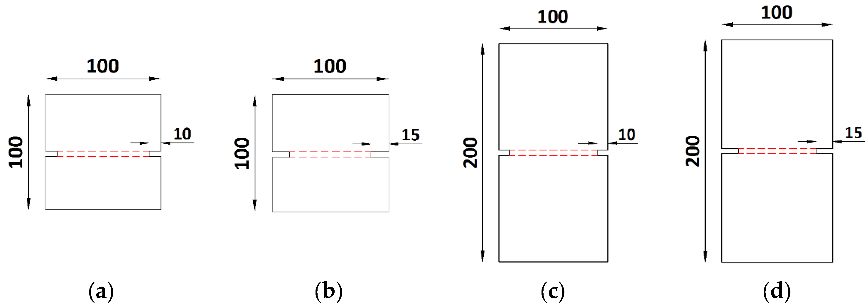
Creating a circumambient groove at mid-height of the cylinder specimen. Two groove depths were investigated in this study, 10 and 15 mm. The main purpose of the groove was to effectively direct the cracking to the groove region where the crack-opening sensors were placed. Lower groove depths than 10 mm were difficult to obtain with the available equipment and higher depths than 15 mm was not desirable due to reduced effective cross sections.
Leveling and cleaning the core-ends thoroughly to avoid skew loads and bond issues during the tensile loading.
Bonding steel plates to each core-end by an epoxy-adhesive to enable proper tensile loading and avoiding local stress concentrations that can occur if mechanical grips are used. It is important that the tensile strength of the epoxy exceeds the tensile strength of concrete to avoid undesired bond failures.
Fixing the cylinder sample to a hydraulic test rig by steel bolts through the steel plates. This setup ensures a reliable procedure for direct tensile testing of concrete cores extracted from existing structures.
Conducting direct tensile tests on the concrete samples in a deformation-controlled loading procedure while recording the maximum load and the corresponding deformations. The deformation-controlled loading scheme enables the detailed monitoring of the fracture process, which can be used to also obtain the material fracture energy.
To enable a fully controllable fracture process, the concrete cylinders needed to be provided with a circumambient groove. The idea of the groove was to control the location of the tensile crack and thereby be able to predict the fracture location and monitor the fracture process accordingly. This experimental study aimed to first develop and evaluate the test procedure, and to secondly investigate the effect of the cylinder height, as well as the groove depth. The test procedure enabled monitoring of the force, displacement and crack width, which can be used to determine the tensile strength as well as the fracture energy of concrete from old existing structures.
A total of 16 concrete cylinders, with a diameter of 100 mm, were cast in steel molds using a normal-weight concrete with a water/cement ratio of 0.55. A standard type of Portland Cement, Bascement Slite, CEM II/A-V 52.5 N, was used as the binder. The complete concrete mix is provided in
Table 1.
Six additional cubes (100 × 100 × 100 mm
3) were cast from the same concrete batch for additional evaluation of the compressive and tensile-splitting strength. The concrete material properties were tested and evaluated in accordance with the EN 12390-3 (2009) and EN 12390-6 (2013) standards. The tested concrete compressive strength and tensile-splitting strength are presented in
Table 2.
The influence of the concrete cylinder height and the groove depth was evaluated in four test setups, exposed to direct uniaxial tensile tests. In each setup, four identical samples were prepared and tested, thereby providing information about the methods’ repeatability, as well as the material deviations.
Table 3 and
Figure 1 present the dimensions of the prepared and tested concrete cylinders and the depth of the mechanically produced groove.
As shown in
Table 3, the height of the cylinders was 100 mm or 200 mm, whereas the depth of the concrete groove was 10 mm or 15 mm. As mentioned earlier, the outer diameter was 100 mm for all cylinder samples, and the corresponding length-to-diameter ratio was thereby 1:1 and 2:1 for the investigated samples.
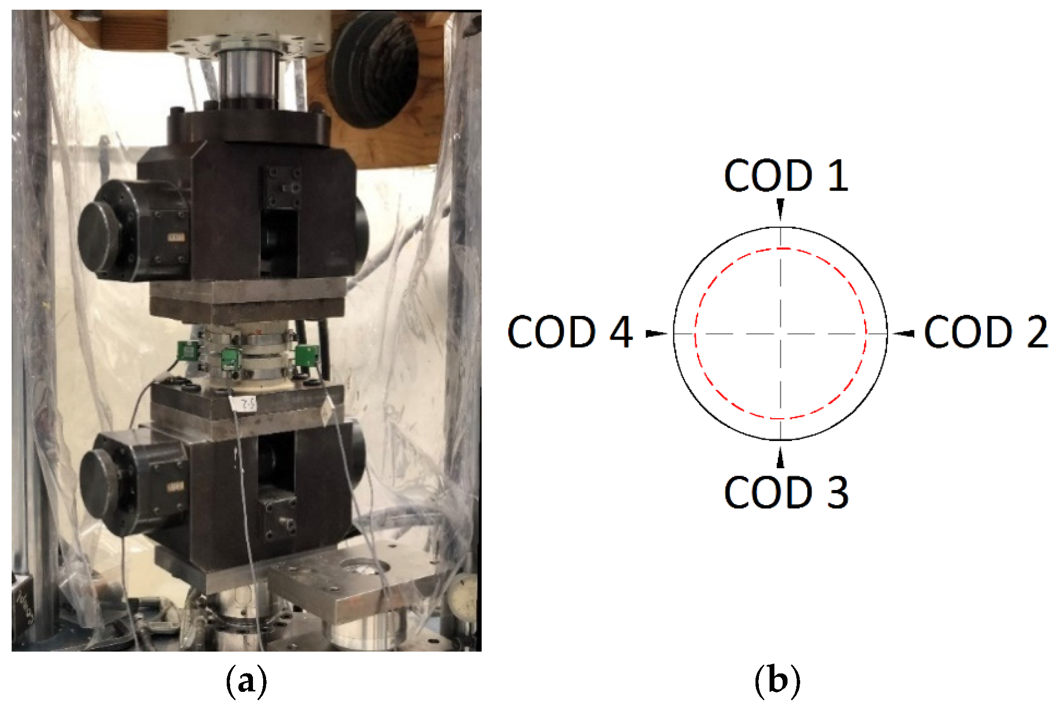
Before the testing started, a 3 mm-wide groove was mechanically lathed around the cylinder’s circumference at mid-height of the test specimen. All 16 cylinders were also completely leveled at both ends to ensure an even load distribution during testing. The direct uniaxial tensile loading was performed in a deformation-controlled servo-hydraulic test rig, with a maximum capacity of 50 kN.
Figure 2a shows an overview of the test setup and loading arrangement. During loading, the crack width was continuously monitored by crack-opening displacement (COD) sensors installed at four perpendicular sides of the cylinder (see the location of CODs in
Figure 2b) over the concrete grooves. To install the CODs properly, two circular steel belts were fixed at each side of the groove. The steel belts were equipped with four steel knives, at 90° from each other, so that the COD sensors could later be mounted on them. The steel belts were tightened parallelly on the perimeter of concrete cylinder so that the clear distance between the top and bottom steel knives was equal to 10 mm at all sides.
Two flat steel plates were attached to the top and bottom bases of the cylinders to fix the test specimen in the test rig and enable the uniaxial tensile load to be applied uniformly on the concrete cylinders. The cylinder-ends needed to be completely levelled to ensure an even stress distribution during the tests. Before applying the adhesive component, the top and bottom bases of the cylinders, as well as the surface of the steel plates, were cleaned thoroughly using isopropanol and acetone. The steel plates were bonded to the concrete cylinders using a two-component epoxy-adhesive, HBM X 60 Epoxy, which provided a sufficient adhesive capacity and tensile strength for the current test procedure. The epoxy-adhesive is characterized as a strain-free adhesive, providing sufficient strength and stiffness, exceeding the corresponding properties of concrete.
One steel plate was attached to the top base of the concrete cylinder while the specimen was still outside the test rig. After adhesive hardening, the steel plate with the test sample was attached to the load cylinder in the test rig through six steel bolts. The bottom steel plate was thereafter fastened to the bottom grip of the test rig with six steel bolts and sufficient epoxy adhesive was distributed evenly over the central part of the bottom steel plate. Finally, the concrete cylinder was attached to the bottom steel plate while the specimen was already inside the test rig. This was achieved by applying a small compressive load on the concrete cylinder to achieve a firm adhesion between the concrete and the steel.
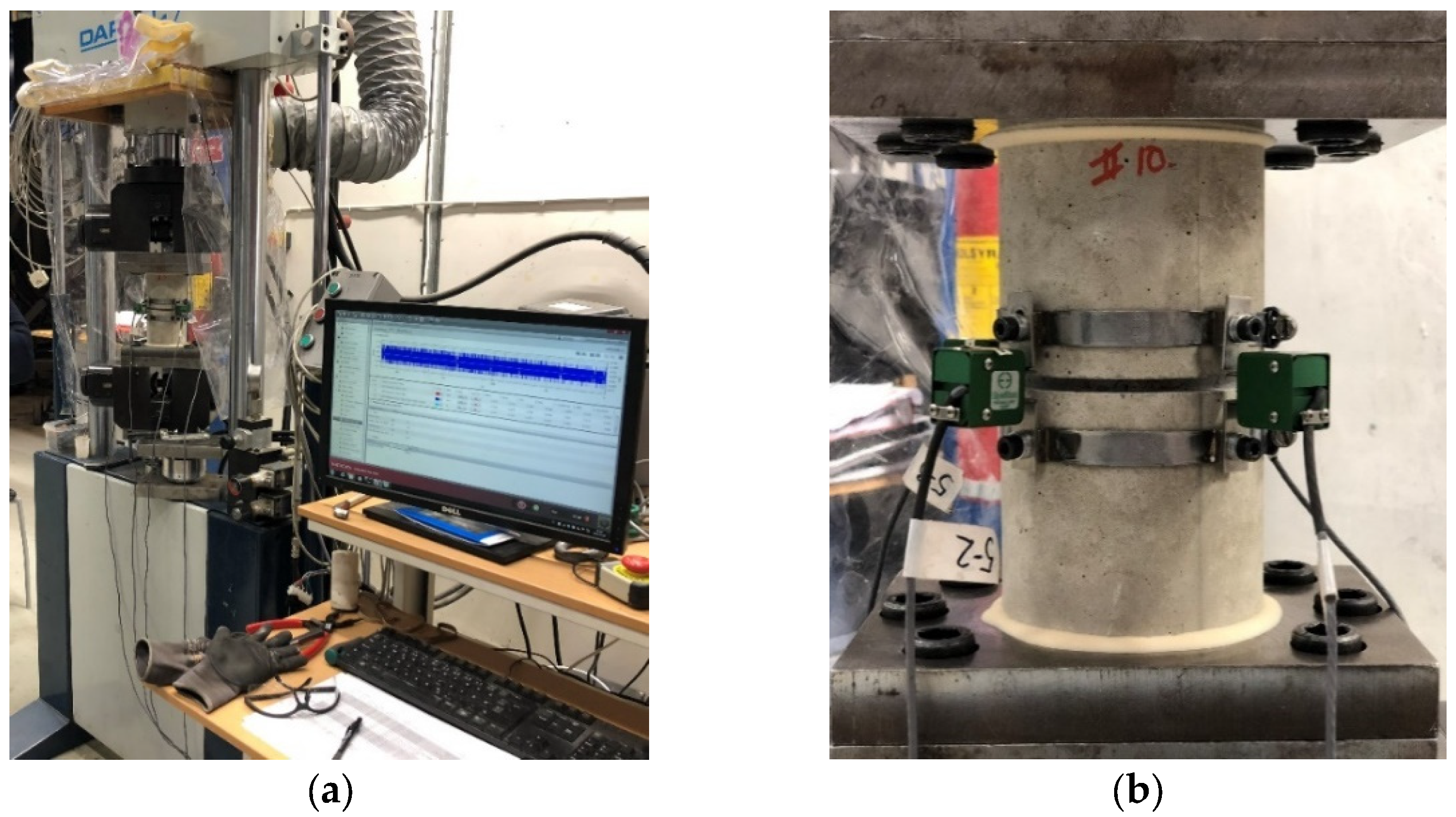
Figure 3 shows details of the loading arrangement and a view of the concrete cylinder mounted inside the test rig.
Figure 3b shows the details on how the concrete cylinder was attached to the steel plates in the top and bottom ends, with some excess epoxy flowing out around the concrete base. The steel plates were attached to the test rig and loading cylinder by six steel bolts in the bottom and top plates, respectively. At mid-height of the concrete cylinder, the mechanically lathed concrete groove can be seen, directing the tensile crack to the desired position, for a precise monitoring. Over the groove, there were four crack-opening displacement sensors monitoring the crack displacements as the concrete was exposed to the tensile load. The entire test procedure was digitally controlled and monitored by the computer seen in
Figure 3a.
To enable capturing the tension-softening branch of the material, all uniaxial tests were mainly performed under deformation-controlled loading conditions. This was achieved by incrementally increasing the average crack-opening value captured by the four COD sensors at a constant rate. The servo-hydraulic loading cylinder was prepared by setting accurate values of the deformation- and load-bias, the displacement limits of the test and the load stages (deformation interval, control mode and rate). In contrast, a load-controlled loading mode would only be able to capture the maximum load and not the tension-softening behavior that can be used to obtain the material fracture energy.
In the first load step, the load applied on the concrete specimen was manually increased from 0 to 0.5 kN, which was the load level where the mean signal of COD sensors started to capture any deformations. The loading was thereafter switched from the load-controlled mode to the deformation-controlled mode, which was guided by the mean deformation, captured by the COD sensors. The deformation rate was kept constant at a value of 0.001 mm/min until the average crack opening reached 0.05 mm. After reaching a crack opening of 0.05 mm, the deformation rate was increased to 0.01 mm/min until the load reached a value of zero. The loading procedure is summarized in
Table 4.
3. Results
Table 5 presents the results and main parameters of all direct uniaxial tensile load tests carried out on 16 cylindric concrete specimens within this study. The cylinder height,
H, was either 100 or 200 mm, with a diameter,
d0, of 100 mm for all cylinders. The diameter inside the grooves,
D, was either 70 or 80 mm, with some small variation according to
Table 5. The table also presents the monitored peak load,
Fmax, the calculated concrete uniaxial tensile strength,
fct, the fracture energy,
Gf, the maximum crack width,
ωmax, and the maximum deformation,
δmax, for each test. The deformation represents the total displacement of the concrete cylinder, including both the crack opening and the material deformation. The mean value (Mean), the standard deviation (SD) and the coefficient of variation (CoV) for each test series were also calculated and presented in
Table 5.
The uniaxial tensile strength of the concrete samples was calculated by dividing the maximum recorded tensile by the cross-sectional area inside the concrete groove. The fracture energy of the concrete samples was calculated as the total area under the stress–crack-width curves. The maximum crack width was obtained from the stress–crack-width curves at the point where the tensile stress in the softening branch reached zero.
The first test of Sample #1 was unfortunately aborted after reaching the maximum tensile load of 16.88 kN and the displacements at the softening branch were not recorded as the test rig was not set to perform a displacement-controlled loading.
During the testing of Sample #2, the top steel plate was detached from the concrete cylinder at an early stage, and thus, this test was also aborted. In a second attempt on the same cylinder sample, the top surface was ground, the steel plate was re-attached to the concrete cylinder and the direct tensile test was carried out again. However, Sample #2 reached a lower maximum tensile load at the second load attempt, compared to its companion samples. This was probably a result of loading the specimen up to approximately 80% of its ultimate tensile capacity during the first loading attempt, and thus, some micro-cracks had already emerged in the concrete. For this reason, the result of Sample #2 was excluded from the calculations of the mean value and the coefficient of variation for the first test series, H100D80.
The direct tensile loading of Sample #4 was unfortunately performed as a load-controlled test, since the COD sensors were not in their correct positions when the tensile loading was initiated. Therefore, the crack-opening displacement was not measured for this sample, and thus, the fracture energy could not be evaluated. However, Sample #4 failed at an ultimate tensile load very close to its companion sample (Sample #3), although the loading was performed in a load-controlled mode.
Sample #9 failed when the adhesive was being applied on the lower steel plate inside the test rig, as the sample was exposed to the compressive load during the adhesive hardening. As mentioned before, the test rig was programmed to apply a small compressive load for 15 min to facilitate the hardening process of the adhesive. No results were therefore recorded for Sample #9.
As seen in
Table 5, the coefficient of variation was relatively small, with values below 10% for the maximum tensile loads, as well as for the concrete tensile strengths. The tensile strength of the 200 mm-high cylinders was slightly lower than the corresponding 100 mm-high cylinder samples, although all samples were cast from the same concrete batch. For the cylinder samples of equal height, the mean tensile strength decreased slightly by increasing the groove depth. In fact, by increasing the groove depth from 10 to 15 mm, the tensile strength decreased by approximately 13% and 6% for the 100 and 200 mm-high samples, respectively.
The variations in fracture energy and maximum crack widths were higher than the corresponding variations in maximum tensile loads and tensile strengths. These properties recorded coefficients of variation larger than 20% within the different test series. This could perhaps be related to natural deviations in the distribution of aggregates, pores, cement paste at the notch cross-section for the tested specimens which could in turn affect the amount of energy dissipated in the fracture process zone and the softening branch of the load–crack-width curve.
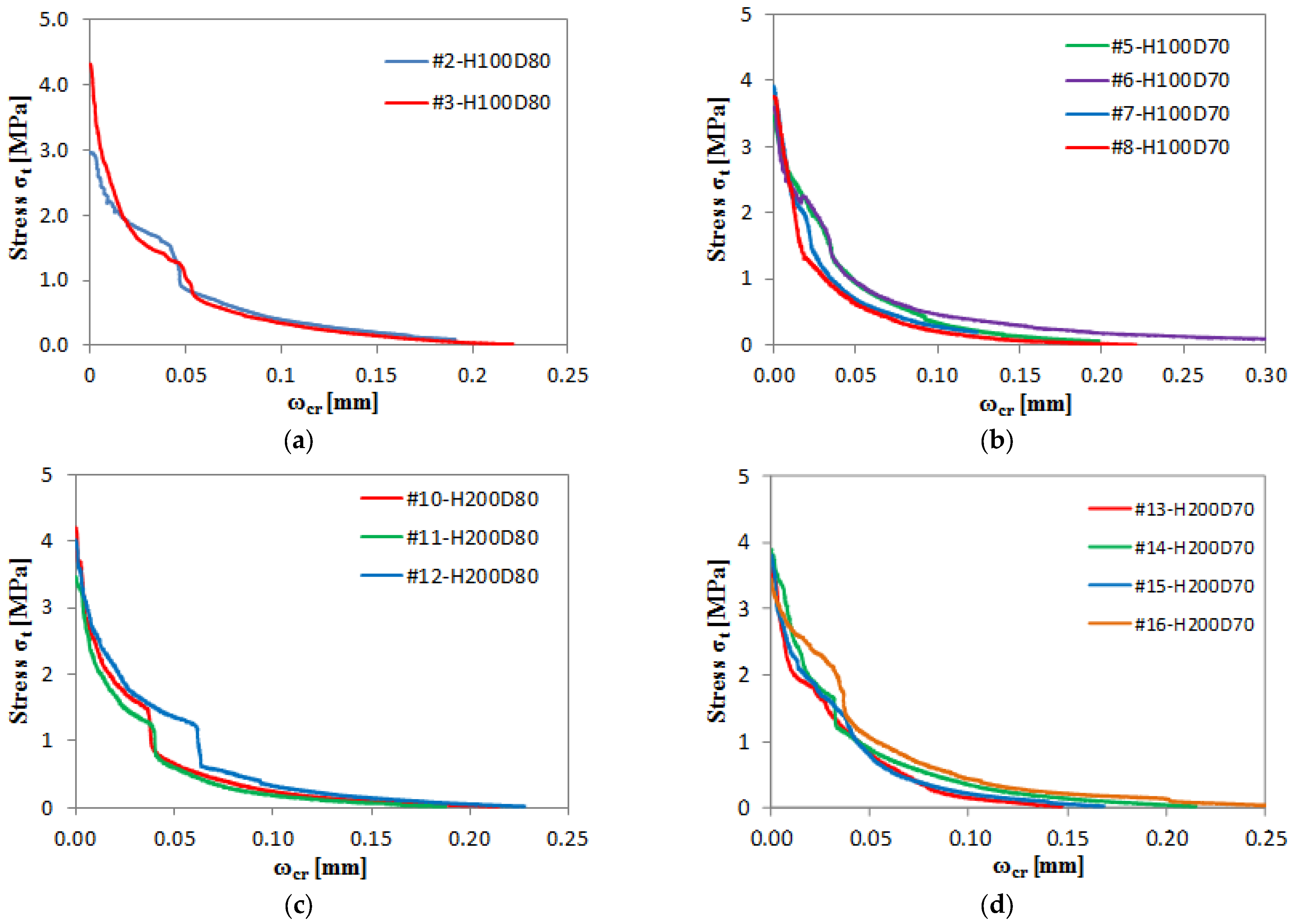
The stress–crack-width curves for all direct tensile tested samples are presented in
Figure 4.
Figure 4a shows the results for the samples with 100 mm height and 10 mm groove depth,
Figure 4b shows the results for the samples with 100 mm height and 15 mm groove depth,
Figure 4c shows the results for the samples with 200 mm height and 10 mm groove depth, and
Figure 4d shows the results for the samples with 200 mm height and 15 mm groove depth.
The tensile cracks formed inside the concrete groove for all samples, ensuring that the proposed test procedure is fully replicable and that the fracture process can be thoroughly monitored for the suggested test set-up. The bond failure that appeared between the concrete and steel plate for the first loading attempt of Sample #2 showed the importance of a thoroughly performed preparation, i.e., the levelling of cylinder edges, cleaning of all surfaces and establishing a good adhesive bond between the steel and the concrete.
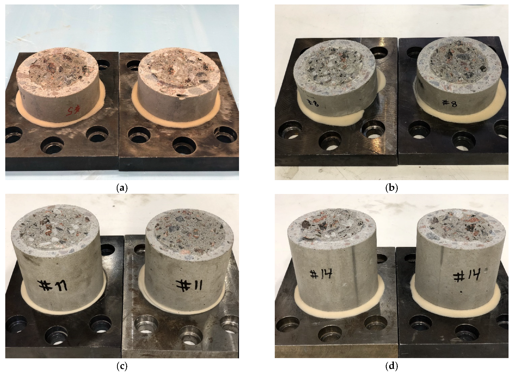
Figure 5 shows examples of failure patterns for sample #5, 8, 11 and 12, respectively, i.e., samples with a 100 mm height and 15 mm groove (#5 and #8), 200 mm height and 10 mm groove (#11), and 200 mm height and 15 mm groove (#14). As seen in
Figure 5, the cracks passed through the cement paste and the aggregates, but the cracks showed a little bit higher tendency for “rounding” some of the larger aggregates, rather than passing straight through them, in the taller cylinder samples, i.e., H200D80 and H200D70.
4. Discussion
This paper proposed a procedure for the direct tensile tests of concrete cylinder cores taken from existing structures to be used as part of a thorough structural health monitoring and assessment procedure. Most of the existing procedures to evaluate the tensile strength of concrete from old structures are based on indirect methods where the concrete is usually tested by flexural, compressive or splitting procedures. However, these test procedures do not measure the direct tensile strength, which has to be calculated by equations based on assumptions about the relationship between the tensile strength and other properties of concrete. Even if the relative assumptions are fairly precise for young concrete, external and internal processes may have changed the relations over time for the concrete in the ageing structure. Therefore, direct tensile tests are a better way to examine and understand the tensile properties of concrete in an old structure.
Another problem with the indirect methods for evaluating the tensile strength of concrete is that they are often recommended to be carried out on cubes, beams or other geometries that are not very easy to extract from an existing structure without severely damaging its condition and crucial properties. Cylinder-shaped concrete cores are both easier to extract and less harmful for the structure. Direct tensile strength tests may also harm the structure, but the impact is far less than corresponding destructive test procedures. The method investigated in this paper was an attempt to test the direct tensile properties of concrete from existing structures. According to previous research, the tensile properties of concrete do not develop in the same way as, for example, compressive strength. This means that, for example, non-destructive methods and other types of destructive methods that estimate tensile strength based on empirical relations may misjudge the actual capacity considerably. The equations are typically also based on tests on much younger concrete and may not be correct for older concrete.
The results of the direct tensile tests, presented in this paper, showed that the recorded differences in tensile strength between concrete cylinders of 100 and 200 mm in height are relatively small. The tests also showed a slightly lower coefficient of variation in the results for the shorter 100 mm sample. The effect of the groove depth was a bit unclear, but on average, the 15 mm grooves showed less variation when analyzing all samples regardless of the sample height. The extraction of smaller core samples will obviously result in less a less harmful impact on the structure, compared to larger samples. The recommendation based on the results from this study is therefore to perform direct tensile tests on cylindrical concrete cores with a height of 100 mm and a mechanically produced groove of 15 mm in depth at mid-height of the core.
Tensile-splitting tests were performed on 100 × 100 × 100 mm cubes from the same batch as the cylinder specimens, and these tests resulted in an average tensile-splitting strength of 5.55 MPa. According to the directions of Eurocode 2, the axial tensile strength should be approximated to 90% of the tensile-splitting strength, i.e., 0.9 × 5.55 = 5.00 MPa, which could be compared to an average tensile strength of 3.81 MPa for the direct tensile strength of the cylinder specimens of this study.
The aim of this paper was to propose, develop and evaluate a general method for direct tensile strength tests of concrete from existing concrete structures. The method proposed was based on direct tensile tests of concrete cylinders extracted from the structure. Direct tensile tests have been performed on new concrete samples before, but the method has not been generally accepted due to several difficulties regarding the procedure for coring, sample preparation, and loading. The novelty of the proposed method is to apply direct tensile testing on concrete from existing structures and the introduction of a groove to promote cracking in a specific region of the sample. The application of direct tensile tests was made possible for cores from existing structures by the method proposed in this paper, including the methodology for coring, sample preparation and loading.
The laboratory tests indicated the importance of preparing the samples thoroughly before testing, including the production of a crack-inducing groove at mid-height of the sample, levelling and cleaning the cylinder bases, and attaching steel plates to the cylinder bases by an epoxy adhesive. The steel plates were bonded to the concrete surface to enable tensile loading without increasing the risk of local cracking or damage from any type of mechanical anchor. The method proved to be successful in terms of feasibility and replicability. However, the bond failure of Sample #2 highlighted the importance of a thorough surface preparation to obtain a strong adhesive bond between the steel plates and the concrete cylinder.
This paper proposed and validated a method for the direct tensile tests of concrete from existing structures, but the tests were, however, conducted only on 16 newly cast concrete cylinder specimens. More tests in general and specifically on concrete cores from real structures are recommended to further validate the test method and to develop a better understanding of how the tensile properties of concrete develop over time. More tests are also needed to establish a sufficient base for statistical validation, and the results may be used to evaluate the current empirical relations for the tensile strength of old concrete. Overall, the study provides important insights regarding the assessment of the direct tensile strength of concrete; the results can be used to improve the structural health monitoring of existing structures and thereby ensure their safety and durability.
5. Conclusions
The aim of this paper was to propose, test and evaluate a general method for the direct tensile strength tests of concrete cylinders from existing concrete structures. A total of 16 concrete cylinders were tested in this study and the main conclusions were:
Direct tensile tests provide a better base for structural assessments than indirect or non-destructive methods. These methods are usually based on empirical relations that may not be valid for old concrete.
A groove can be used to direct the cracking to a desired region for effective monitoring of the load response.
The concrete samples should be firmly glued to steel plates at the cylinder ends to enable tensile loading without local stress concentrations. Epoxy adhesives provide excellent properties for this purpose.
Cylinders with a height of 100 mm and a 15 mm groove at mid-height provided a good setup for effective and reliable testing.
Further tests are recommended for further validation and to provide a better statistical base for the method.


