Article

Trajectory Control in Discrete-Time Nonlinear Coupling Dynamics of a Soft Exo-Digit and a Human Finger Using Input–Output Feedback Linearization

by
Umme Kawsar Alam
,
Kassidy Shedd
and
Mahdi Haghshenas-Jaryani
*
Department of Mechanical and Aerospace Engineering, New Mexico State University, Las Cruces, NM 88003, USA
*
Author to whom correspondence should be addressed.
Automation 2023, 4(2), 164-190; https://doi.org/10.3390/automation4020011
Submission received: 14 April 2023 / Revised: 17 May 2023 / Accepted: 26 May 2023 / Published: 31 May 2023
(This article belongs to the Collection Smart Robotics for Automation)

Abstract

:
This paper presents a quasi-static model-based control algorithm for controlling the motion of a soft robotic exo-digit with three independent actuation joints physically interacting with the human finger. A quasi-static analytical model of physical interaction between the soft exo-digit and a human finger model was developed. Then, the model was presented as a nonlinear discrete-time multiple-input multiple-output (MIMO) state-space representation for the control system design. Input–output feedback linearization was utilized and a control input was designed to linearize the input–output, where the input is the actuation pressure of an individual soft actuator, and the output is the pose of the human fingertip. The asymptotic stability of the nonlinear discrete-time system for trajectory tracking control is discussed. A soft robotic exoskeleton digit (exo-digit) and a 3D-printed human-finger model integrated with IMU sensors were used for the experimental test setup. An Arduino-based electro-pneumatic control hardware was developed to control the actuation pressure of the soft exo-digit. The effectiveness of the controller was examined through simulation studies and experimental testing for following different pose trajectories corresponding to the human finger pose during the activities of daily living. The model-based controller was able to follow the desired trajectories with a very low average root-mean-square error of 2.27 mm in the x-direction, 2.75 mm in the y-direction, and 3.90 degrees in the orientation of the human finger distal link about the z-axis.

1. Introduction

Every year, 800,000 people suffer a new stroke in the United States (this number globally is 13,000,000) [1]. Stroke remains the leading cause of long-term disability in the human upper extremities (more than 80%), and only 10% can regain partial mobility [2]. Clinical studies have shown that early access to physical and occupational therapy interventions with intensive/repetitive movements, such as continuous passive motion (CPM), help restore functionalities in the impaired hand of post-stroke individuals [3]. However, the lack of patient compliance and limited availability of resources and therapists hinders the efficacy and effectiveness of these approaches. On the other hand, robotic systems are very effective in performing repetitive and labor-intensive tasks. Several robotic devices have been developed and studied for upper limb rehabilitation [4]. Particularly, wearable robots for upper-body rehabilitation and physical assistance have benefited from intrinsic mechanical compliance inherited in soft robotic approaches. This feature makes them suitable for safe physical interaction with the human body [5,6]. Additionally, soft wearable robots for upper limb rehabilitation address the limitations of their rigid counterparts (i.e., conventional rigid robots), including complex mechanisms, heavy weight, lack of safety, and cost [7,8,9,10,11]. More than 50 soft exoskeletons have been developed over the past 15 years for hand rehabilitation [12,13]; these robots still provide limited capabilities for interacting with the human hand due to their simple control schemes, primarily based on the kinematics of robots [14,15].
There has been significant progress in designing and developing robotic hand exoskeletons for rehabilitation, and assistive tasks (more than fifty soft hand exoskeletons have been developed over the past 15 years [12,13,16]). Soft robotics provides potential solutions to address the complex mechanisms, heavy weight, bulky size, high cost, and safety issues involved in conventional (rigid) robots [4,9,13,17,18,19,20]. Three major groups of soft robotic hand exoskeletons have emerged: (1) fluid-actuated elastomeric/textile-fabric robots (e.g., the pneumatic artificial muscle-based gloves [15,21], Harvard’s soft robotic glove [9,22], fabric-based gloves [23,24,25], elastomeric gloves [26,27,28,29,30]); (2) cable/tendon-driven robots (e.g., GraspyGlove [31], and Exo-Glove Poly [32,33]); and (3) hybrid soft-and-rigid robots (e.g., REHAB Glove developed at UTARI [10,11,14,34], Exo-Glove PM [35] developed at SNU, and SeptaPose Assistive and Rehabilitation (SPAR) developed at Rice University [20]). Despite the simple mechanisms of the exoskeletons in group 1, their major drawbacks are the low generated force/torque and the lack of controllability over distinct human finger joints [6,11,20,36]. On the other hand, cable/tendon-driven mechanisms [31,32,33,37,38,39,40,41,42,43,44,45] generate higher force/torque; however, friction and backlash effects, as well as the need to maintain constant tension for the tendons, are some of the challenges for their control [46]. Hybrid designs, combining soft components with partially rigid structures, have recently emerged and been studied to address the shortcomings of other exoskeletons [11,20,35,36,47,48]. These designs have individual joint control to some extent, bidirectional motion, and can move freely in 3D space. However, their control functionality is rather limited for a wide array of real-world scenarios [19,20].
Well-known control techniques used in robotics have mainly been derived for rigid multibody systems with a limited number of degrees of freedom (DoF) in order to accomplish specific and repetitive tasks. However, these techniques are not directly applicable to control soft robots due to their continuously deforming nature, large deformation, and nonlinearity in both materials and geometries, leading to complex kinematics and dynamics [7,8,49,50]. Even with recent extensive studies and promising results in soft robots’ control, particularly bio-inspired soft robotic arms [51], the control of soft wearable robots (e.g., hand exoskeletons) is still limited to simple control schemes such as open-loop, model-free, and low-level sensor-enabled closed-loop control [8,9,36,52,53,54]. Current control algorithms are mainly designed from the perspective of robotic exoskeleton operation to apply the desired position/force to the human hand for gross motion and grasp. Low-level feedback control algorithms have been introduced by integrating internal/external sensors into soft robots, which helps to partially correct their dynamical responses in real time [7,9,10,11,13,55,56,57,58]. A proportional-integral position controller was used for the power-assisted glove to assist functional grasping activities for stroke survivors [15]. A model-free sliding-mode controller was used to regulate the pressure applied to the soft actuators [9] in Harvard’s robotic glove. Although these model-free techniques [59] eliminate the explicit need for the dynamic model of these highly compliant systems, their performance strongly depends on the consistency and robustness of the system, making their successful implementation limited to repetitive tasks. Tang et al. proposed a probabilistic model-based learning control approach to address the challenges with model-based control approaches while learning through the human-robot interaction to perform tasks [52]. Some exoskeletons used impedance/admittance of the tendon-driven mechanism as the basis of control. Jeong et al. [38] proposed a position-based impedance control (admittance control) for the Exo-Glove with soft tendons [32], which made the tendons act as a virtual compliant spring; however, it does not provide individual control for each joint. Studies have shown that abnormalities in impedance and motor control may vary from joint to joint such that independent control of each joint through the exoskeleton may be beneficial for an effective operation [60]. Human intents, as reference inputs, have been integrated to guide the operation of exoskeletons [9,15]. Biological sensors, such as surface electromyography (sEMG) [9,15,20,43,59,61,62] and electroencephalography (EEG); motion sensors, such as inertial measurement units (IMUs) [10,14], electromagnetic tracking [9], and infrared distance sensors [31]; internal pressure and tactile force sensors; or a combination of these sensors [15] have been used. Though these approaches provide intuitive gross hand and finger motion control, the aforementioned algorithms are mainly for a pure sensor-based position or grip force control, which lacks the required hybrid force-position-based dexterous manipulation to perform fine motor skills. Additionally, extensive reviews of literature on soft robotic hand exoskeletons [52,53,54,63] have shown that current control algorithms do not consider multi-joint control and the multi-contact-point interaction of the human fingers and the interaction of soft wearable robots, thereby impeding the achievement of complex fine motor functional tasks. Thus, a new control paradigm from a human-robot interaction perspective (i.e., a bilateral approach to facilitate performing collaborative tasks) is needed to take into account the physical interaction between the soft robot and the human hand.
The effective operation of soft robotic hand exoskeletons for physical therapy and assistive motion requires the utilization of a multi-joint control scheme that takes into account the physical interactions between the robot and the human hand [34,64,65]. The highly nonlinear nature of soft robots’ dynamics and control, along with the complexity of pHRI and users’ biomechanical variation, have impeded the research related to soft wearable robots’ control [8,64,65]. Some early works in this field have developed dynamic models and simple control algorithms for soft pneumatic actuators in the form of a continuous fluidic elastomer actuator (FSA) [66,67]. Physical interactions between an FSA and a human finger model were experimentally studied [66] using tactile sensors embedded between the human finger model and the soft robot. In another work, the interactions of a fabric-based pneumatic exoskeleton with a human finger were studied through modeling and experimental validation [35]. None of these works has considered multi-contact-point interaction between the soft robotic digit and the human finger. Our previous work includes extensive studies of design, modeling, and kinematic-based control algorithms on a hybrid soft-and-rigid actuator-based hand rehabilitation robot (REHAB Glove) [10,11,34]; modeling and characterization of physical human-robot interaction (pHRI) in wearable soft hand robots [68,69]; a kinematic-based adaptive control of a bilateral rehabilitation robot [14]; and simulation-based quasi-static force and position control [70]. In our recent work, single-input single-output (SISO) quasi-static model-based adaptive position control of soft exo-digit and the human finger physical interaction was developed and experimentally verified for a step input and trajectory tracking cases [63].
This work presents a multi-joint quasi-static model-based control algorithm for controlling the motion of a soft robotic exoskeleton digit (exo-digit) with three individually controlled joints while physically interacting with the human finger. The contributions of this work are listed as follows,
  • Analytical modeling formulation of quasi-static physical interaction between the human finger model and a soft robotic exo-digit with individually controlled joints was derived.
  • A feedback linearization control algorithm was derived for a nonlinear discrete-time multiple-input multiple-output (MIMO) state-space representation.
  • The feedback linearizability and stability conditions of the nonlinear discrete-time state-space model of soft exo-digit and human finger physical interaction were studied.
  • Experimental testing of the soft exo-digit interacting with a human finger model for tracking a desired trajectory was carried out.
The structure of this paper is set as follows: The quasi-static analytical model is derived in the Section 2 with the forward and inverse kinematics formulations of the human finger model and the Jacobian of each model. Section 3 presents the nonlinear discrete-time state-space model of a soft robot and the human finger physical interaction. Additionally, a model-based control law was derived based on the input-output feedback linearization for trajectory tracking of the human fingertip pose while assisted by the soft exo-digit. Section 4 describes the implementation of the electro-pneumatic control system hardware for testing the trajectory tracking cases, and finally, Section 5 discusses the results obtained from simulations and experimental testing, which validated the presented model-based controller.

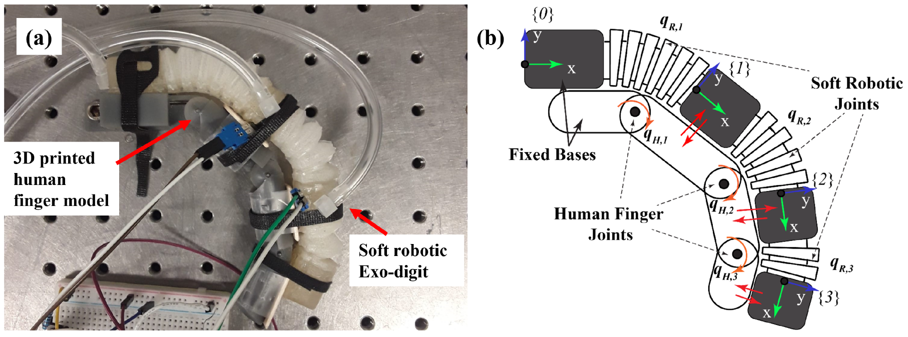
2. Quasi-Static Model of Physical Human-Soft Robot Interaction

The physical interaction between a human finger and a soft-wearable robot is studied using a model of soft robotic exo-digit and a corresponding human finger model, as shown in Figure 1a. Continuous passive motion (CPM) therapy is the main application of this human-robot interaction. In CPM, the robot actively applies slow, repetitive motions to the user’s hand while the user is passive. Thus, the physical interaction can be modeled as a quasi-static process. The soft robotic exo-digit consists of three soft continuous actuating sections (i.e., half-bellow shape hollow structures) representing the joints of the soft-bodied robot and four semi-rigid blocks linked through those pseudo joints. The human finger is modeled as an articulated rigid multi-body with three revolute joints representing the metacarpophalangeal (MCP), proximal interphalangeal (PIP), and distal interphalangeal (DIP) joints of the human finger. Rotational (torsional) springs are integrated at each joint of the human finger model to replicate the biomechanical stiffness of the human joints. The torsional springs are selected from the vendor with a stiffness of k 1 h = 5.9 × 10 4 N·m/deg, k 2 h = 3.83 × 10 4 N·m/deg, and k 3 h = 1.07 × 10 4 N·m/deg for MCP, PIP, and DIP joints, respectively. The semi-rigid links of the soft robotic exo-digit are attached to the links of the human finger model (as shown in Figure 1a), where the physical interaction occurs; see Figure 1b. Frames are attached to each soft-bodied link to describe the kinematic motion of each segment. The quasi-static interaction of the soft robotic digit and the human finger model were decoupled to derive the equations of motion (balance) for each body where the physical interaction (contact forces) is distributed along the length of the two bodies. It is assumed that the reaction force between the human finger and the soft robotic digit happens at the center of each link and is dominant in the direction normal to the soft-bodied links. Figure 2 shows the workspace of the human finger model and the soft exo-digit. In both cases, the joint angles range from 0–90° for MCP, 0–100° for PIP, and 0–70° for DIP, and the link length is measured by the distance from one joint to another. The biomechanical range of motion of a human finger served as the basis for setting these ranges.
From Figure 2 it can be seen that the shape of the workspace for both the human finger model and the soft exo-digit is the same.

2.1. Kinematics of the Human Finger Model

The human finger was modeled as a serial kinematic chain of three moving rigid links and a fixed-base link with a single-degree-of-freedom hinge joint connecting adjacent links as shown in Figure 1. The motion of the joints is described by q H = [ q H , 1 , q H , 2 , q H , 3 ] T . The forward kinematics of the human finger model, L ( q H ) , can be described similar to a classical planar three-link robotic arm where the pose of the tip of the human finger, ( x , y , θ ) , with respect to the reference frame is given as follows,
x = 2 l 1 c 1 + 2 l 2 c 12 + l 3 c 123
y = 2 l 1 s 1 + 2 l 2 s 12 + l 3 s 123
θ = q H , 1 + q H , 2 + q H , 3
where the following notations are used in the entire paper for sine and cosine functions, s i = sin ( q i ) , c i = cos ( q i ) , s i j = sin ( q i + q j ) , c i j = cos ( q i + q j ) , s i j k = sin ( q i + q j + q k ) , and c i j k = cos ( q i + q j + q k ) .
Additionally, the Jacobian matrices, J H , i , which map the joint velocities q ˙ H to the linear υ H , i and angular ω H , i velocities of each link can be obtained as
υ ^ H , i = [ v H y , i v H x , i ω H z , i ] T = J H , i q ˙ H
J H , 1 = l 1 s 1 0 0 l 1 c 1 0 0 1 0 0
J H , 2 = 2 l 1 s 1 l 2 s 12 l 2 s 12 0 2 l 1 c 1 + l 2 c 12 l 2 c 12 0 1 1 0
J H , 3 = 2 l 1 s 1 2 l 2 s 12 l 3 s 123 2 l 2 s 12 l 3 s 123 l 3 s 123 2 l 1 c 1 + 2 l 2 c 12 + l 3 c 123 2 l 2 c 12 + l 3 c 123 l 3 c 123 1 1 1
where υ ^ H , i is a vector that combines the planar linear and angular velocity components, l i is the length of ith link. Note these Jacobian matrices are derived for the center point of each link where the interaction force applies.

2.2. Coupled Human–Robot Interaction Quasi-Static Model

The multi-contact points quasi-static models of the human finger and the soft robotic exo-digit, developed separately, are presented here. For simplifying the form of equations, the contact forces, expressed in the reference frame, are written in terms of body-fixed frames as follows: f R H , i = i 0 R i f R H , i and f H R , i = i 0 R i f H R , i where i f R H , i = i f H R , i = [ 0 , f i , 0 ] T are the contact forces expressed in the body frame { i } . Introducing a special human–robot contact force vector of f R H * = f H R * = [ f 1 , f 2 , f 3 ] T , which combines the body-fixed frame forces, the quasi-static equations can be written in the following compact form, where the quasi-static equations for the human finger model are defined as follows:
K H q H ( J H * ) T f R H * = 0
where the special Jacobian matrix ( J H * ) T and the joint stiffness matrix K H are defined as follows:
( J H * ) T = l 1 l 2 + 2 l 1 c 2 l 3 + 2 l 2 c 3 + 2 l 1 c 23 0 l 2 l 3 + 2 l 2 c 3 0 0 l 3 ,
K H = k 1 h 0 0 0 k 2 h 0 0 0 k 3 h .
Similarly, the quasi-static equations for the soft robotic exo-digit are defined as
τ ( q R ) + B R p ( J R * ) T f H R * = 0
where
( J R * ) T = e 11 e 12 e 13 0 e 22 e 23 0 0 e 33
e 11 = l ^ 1 q 1 2 ( 1 c 1 ) + d 1 e 22 = l ^ 2 q 2 2 ( 1 c 2 ) + d 2 e 33 = l ^ 3 q 3 2 ( 1 c 3 ) + d 3 e 23 = d 3 q 2 2 q 3 + l ^ 2 q 3 c 3 + l ^ 3 q 2 2 s 3 l ^ 2 q 3 c 23 l ^ 2 q 2 q 3 s 3 + 2 d 2 q 2 2 q 3 c 3 q 2 2 q 3 e 12 = d 2 + 2 d 1 c 2 + c 12 ζ 1 + ζ 3 + s 12 ζ 1 ζ 3 e 13 = d 3 + 2 d 2 c 3 + 2 d 1 c 23 + c 123 ζ 4 + ζ 1 + ζ 3 + s 123 ζ 5 + ζ 2 ζ 3
ζ 1 = l ^ 1 ( c 1 + q 1 s 1 1 ) q 1 2 ζ 2 = l ^ 2 ( s 1 q 1 c 1 ) q 1 2 ζ 3 = l ^ 2 ( c 12 c 1 ) q 2
ζ 4 = l ^ 3 ( s 123 s 12 ) q 3 ζ 5 = l ^ 3 ( c 123 c 12 ) q 3
and p = [ p 1 , p 2 , p 3 ] T is the actuation pressure vector (control inputs), and B R is a diagonal matrix of the first moment of the cross-section area of each soft segment where the internal pressure actuation p i acts on them,
B R = r p 1 A p 1 0 0 0 r p 2 A p 2 0 0 0 r p 1 A p 3 .
It is obvious that both upper triangular special Jacobian matrices ( J H * ) T and ( J R * ) T are invertible by assuming q 0 . Now, Equations (8) and (9) are combined to derive a collective model for pHRI. The combined model will be used for the control algorithm development. Eliminating the force vectors, f R H * and f H R * between Equations (8) and (9) with q R = q H = q yields
τ ( q ) + B R p ( J R * ) T ( J H * ) T K H q = 0
which represents the coupled quasi-statics of the human–robot model. The torque term is given as τ ( q ) = [ τ s 1 ( q 1 ) , τ s 2 ( q 2 ) , τ s 3 ( q 3 ) ] T , where
τ s i ( q i ) = k = 0 13 a b , k q i k j = 2 7 b b , j q i j + k = 0 17 a h , k q i k j = 2 12 b h , j q i j + k = 1 14 a t , k q i k j = 0 8 b t , j q i j .
The coefficients of the polynomials of the rational functions in Equation (11) are given in the Appendix file of the Supplementary Materials folder. Note that these coefficients are functions of material properties (i.e., the Yeah third-order hyperelastic model [11]) and the geometry of the soft actuator segments).

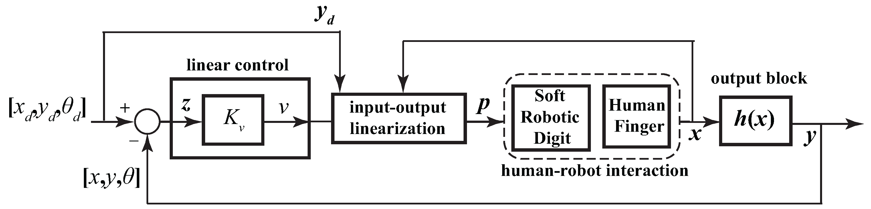
3. Feedback Linearization Control

3.1. Nonlinear Discrete-Time State-Space Representation

Control problem: a square multiple-input multiple-output (MIMO) tracking control problem is considered here such that the pose of the human fingertip (i.e., ( x , y , θ ) ) follows the reference inputs using the soft robotic exo-digit. For this purpose, the coupled quasi-static equation, shown in Equation (10), can be written into a nonlinear discrete-time state-space form with affine control as follows for position control,
x k + 1 = f ( x k ) + j = 1 3 g j ( x k ) p k j y k = h ( x k )
where x k = q ( k ) is the state vector at time index k, p k j is the jth control input at time index k in p k = [ p k 1 , p k 2 , p k 3 ] T , and the targeted output vector y k = h ( x k ) is defined as the position vector of the human fingertip [ x ( k ) , y ( k ) ] T = L ( x k ) , given in Equations (1) and (2), and the bending of the human finger distal end (i.e., θ ( k ) = x k 1 + x k 2 + x k 3 ). f ( x k ) and g j ( x k ) are given as follows:
f ( x k ) = ( ( J R * ) T ( J H * ) T K H ) 1 τ ( x k )
and
G ( x k ) = [ g 1 , g 2 , g 3 ] = ( ( J R * ) T ( J H * ) T K H ) 1 B R .
We assume that there is an equilibrium point ( x k e , p k e ) that satisfies x k + 1 = 0 in Equation (12).

3.2. Input–Output Feedback Linearization

Using the notion of input–output linearization [71,72], the discrete derivative of the output y k in Equation (12) yields
y k + 1 = h ( x k ) x k f ( x k ) + j = 1 3 h ( x k ) x k g j ( x k ) p k j = L f h ( x k ) + j = 1 3 L g j h ( x k ) p k j
where
L f h ( x k ) = h ( x k ) x k f ( x k )
and
L g j h ( x k ) = h ( x k ) x k g j ( x k ) j = 1 , 2 , 3
are Lie derivatives of h ( x k ) with respect to the field functions f ( x k ) and g j ( x k ) , respectively. A remarkable result from the work by Jayaraman and Chizeck [73] has shown that a nonlinear discrete-time system like Equation (12) with dimension n is feedback linearizable if it has vector relative degree { r 1 , , r m } , where m is the dimension of the control input p k , such that r 1 + r 2 + + r m = n . Note that the MIMO system has a uniform relative degree of one given that L g j h ( x k ) 0 in Equation (12) for j = 1 , 2 , 3 in the neighborhood of x k e . The details of analysis on the value of L g j h ( x k ) and its variation with respect to the configuration space ( q 1 , q 2 , q 3 ) of the soft exo-digit are given in Appendix A.
The goal is to find a coordinate transformation, z k = T ( x k ) and a feedback control p k = γ ( x k , υ k ) to linearize Equation (12) for the mapping between the inputs and outputs for the trajectory tracking problem. Thus, z k = y k y k d , i.e., the trajectory tracking error, is selected where y k d is the vector of the reference inputs (i.e., the desired outputs) which the human finger controlled by the soft exo-digit must follow. Given the discrete derivative of z k ,
z k + 1 = y k + 1 y k + 1 d ,
and substituting Equation (15) into Equation (16) yields the new state space model in the new coordinates expressed by a set of scalar equations for i = 1 , 2 , 3 given as follows:
z k + 1 i = L f h i ( x k ) + j = 1 3 L g j h i ( x k ) p k j y k + 1 d , i
if the inverse of L G h ( x k ) ,
L G h ( x k ) = h ( x k ) x k g 1 ( x k ) , g 2 ( x k ) , g 3 ( x k )
exists, then the control input vector ( p k ) (i.e., the actuation pressure of the soft segments) can be derived as a nonlinear state feedback control [73],
p k = L G 1 h ( x k ) L f h ( x k ) + υ k + y k + 1 d
to linearize the input–output map which transforms Equation (12) to its equivalent linear system as follows:
z k + 1 = υ k .
Invertibility of Equation (18) is shown in Appendix A. The additional control input υ k will be defined by a linear full-state feedback control as follows:
υ k = K υ z k ,
where K υ R 3 × 3 is a diagonal feedback gains matrix. Choosing K υ to be positive-definite guarantees exponentially asymptotic stability of the input–output linear system, Equation (20), and consequently, guarantees the stability of the original nonlinear state-space system, Equation (12), to follow the reference signal y k d . The control block diagram is shown in Figure 3.

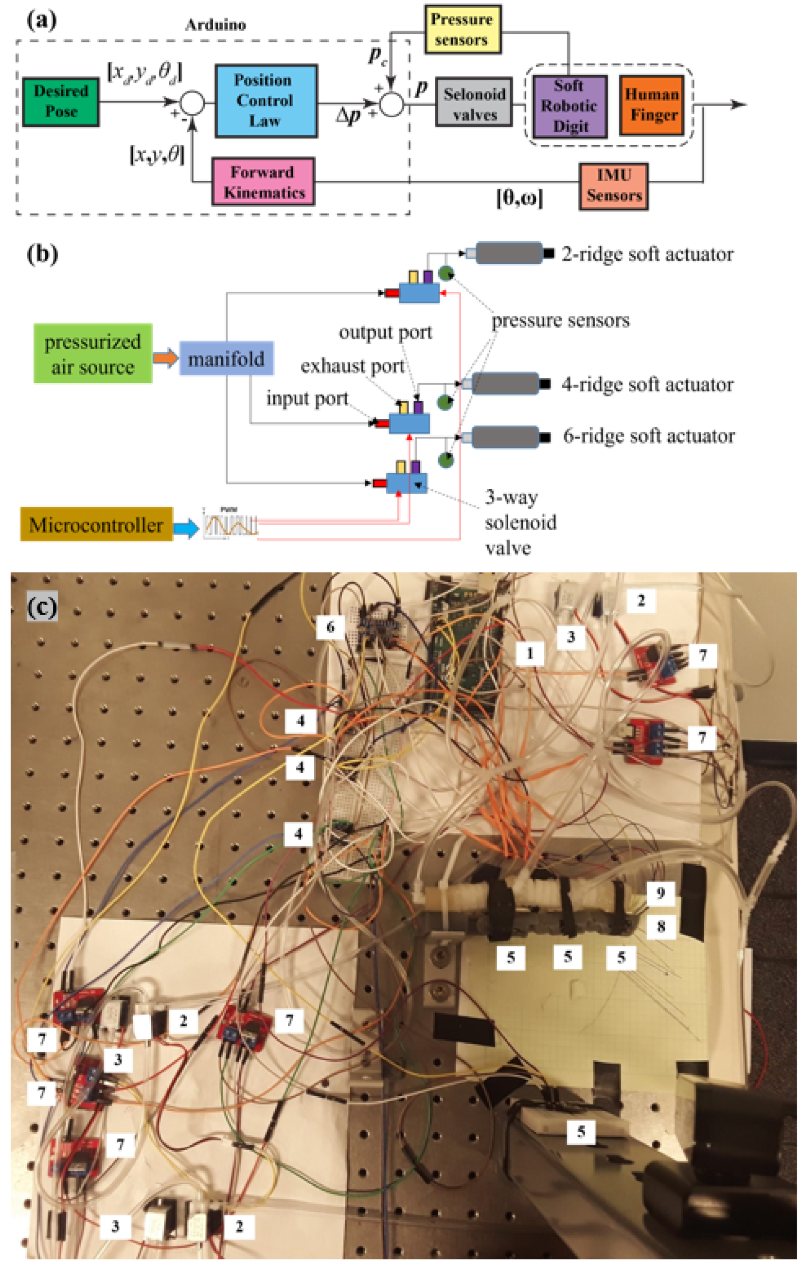
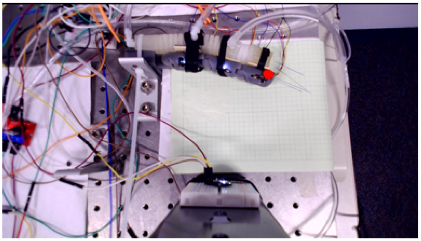
4. Control System Implementation

An electro-pneumatic control system was developed to examine the model-based control algorithms derived in Section 3. The control system is based on modulating the actuation pressure, where the control action will be determined based on the error between the desired trajectories (pose of the finger distal end) and the actual feedback (i.e., determined through IMU sensors reading and the forward kinematics of the human finger) as shown in Figure 4a. An Arduino (Arduino, MEGA 2560, Arduino LLC, Piscataway, NJ, USA) is used as the microcontroller for controlling the overall operation, receiving sensing information, and transmitting control commands based on the control algorithms. Four inertial measurement units (IMUs, 6-DOF, 3 Gyros and 3 Axes Accelerometer, DFRobot, San Francisco, CA, USA) are integrated into the rigid links of the human finger model (one at the fixed base as the reference and the other three in each moving link) to measure the angular position and velocity of moving links and determine the joint positions and velocities. An algorithm combines the gyro and accelerometer measurement to calculate a stable angular position with very low drift. Additionally, in-line pressure sensors (ASDXACX030PG, Honeywell, Richardson, TX, USA) are used for measuring the internal pressure of each soft actuator segment. The output of the IMU sensors is used to determine the pose of the fingertip based on the forward kinematics of the human finger model expressed in Equations (1)–(3). The actual poses were compared against the desired input to calculate the errors which are used in the position control law to determine the actuation pressures of each individual soft joint. The final control action (air pressure p) is obtained by a combination of change in actuation pressure/vacuum ( Δ p ), and the current internal pressure ( p c ) measured by in-line pressure sensors, p = p c + Δ p , where the pressure change ( Δ p ) is associated with the tracking error and quasi-static model of the human-robot interaction and will be determined by Equation (19). A PWM control scheme was used, as shown in Figure 4b, through an Arduino to control the opening and closing cycles of three-way solenoid valves proportional to the input control value for achieving the pressure change. A two-way valve is integrated into the exhaust port of each three-way valve to control the pressure relief process. A PWM signal was sent to the two-way valves for closing and opening. Note that the positive change in pressure leads to pressurizing the soft actuator while the negative change in pressure causes vacuuming (or air bleeding). Each soft actuator segment (soft exo-digit module) is individually controlled, while their collective controlled actuation leads to tracking the desired movement of the human finger by the soft exo-digit. Table 1 provides the description and justification of each component used in the experiment.
Figure 4c shows the actual electro-pneumatic board, the soft-robotic exo-digit, and the human finger model experimental setup with each component labeled according to the corresponding number in Table 1.

5. Results and Discussion

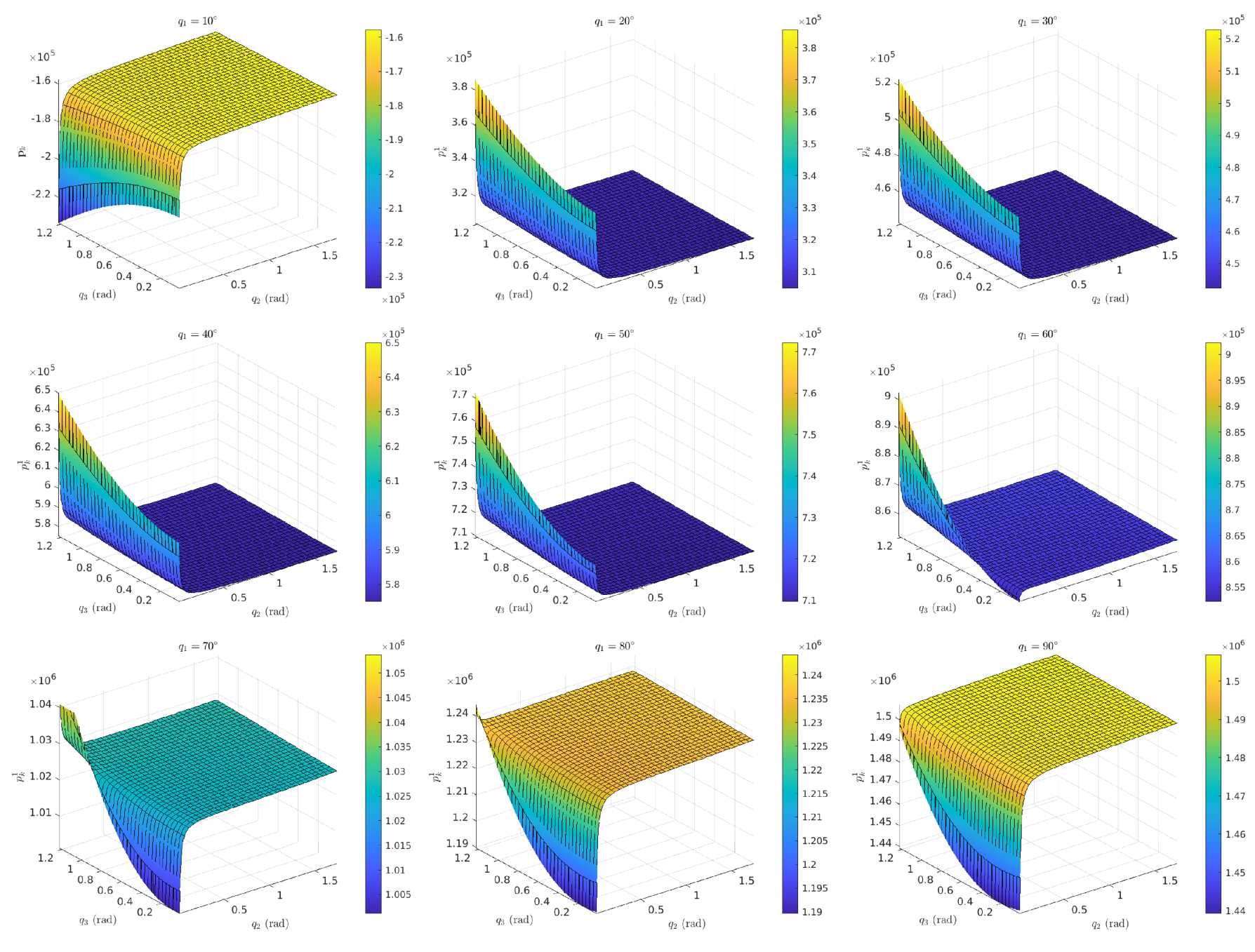
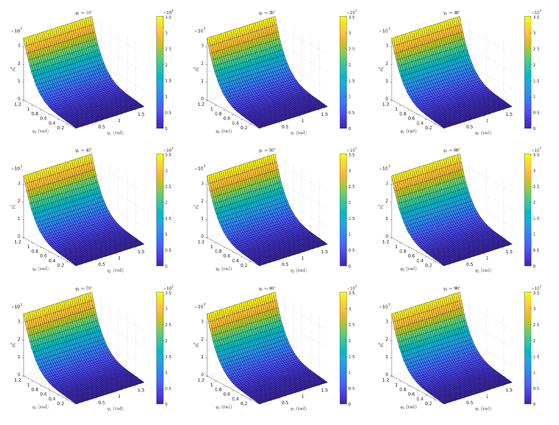
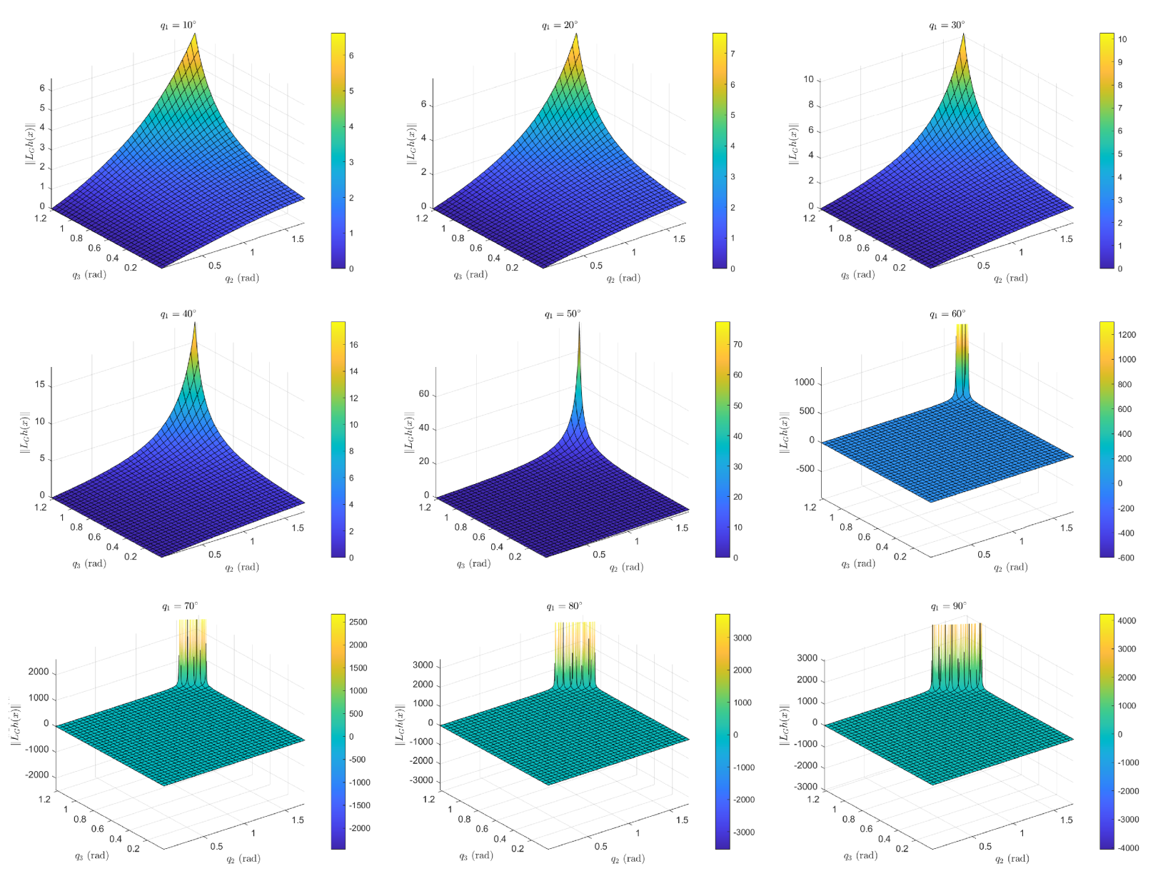
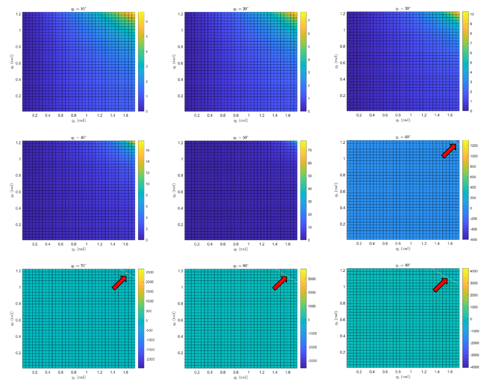
5.1. Analysis of the Control Law

The control law obtained for the actuation pressure of the soft robotic exo-digit expressed in Equation (19) was examined for the configuration space of the robot where y k + 1 d = 0 . This examination provides insights into how the controlled pressure of each soft actuator segment varies with respect to the variation of joint angles q = [ q 1 , q 2 , q 3 ] T . Note that the actual movement of the soft robotic exo-digit along with the human finger (i.e., particularly the pose of the tip of the finger) in the Cartesian space will be corresponding to a subset of this full configuration space of the soft robot. Understanding the overall behavior of required control pressure helps to better determine the constraints on the physical human–robot interaction and the design of the control system for experimental testing. As mentioned before, the range of each joint angle is set based on the biomechanical range of motion of the human finger (MCP: 0–90°, PIP: 0–100°, and DIP: 0–70°). The plots are provided for each actuation pressure in Figure 5, Figure 6 and Figure 7. The color variation in these plots corresponds to changes in pressure, with blue indicating the lowest pressure and yellow indicating the highest. The exact pressure values can be determined from the vertical line on the right side of each figure. It is shown that the pressure actuation for the first joint varies with respect to the change of all three joint angles, although this behavior is different for the other two joints where they are independent of the variation of q 1 (see Figure 6 and Figure 7). Additionally, for the third joint actuation pressure p k 3 , it seems its value does not depend on the variation of the second joint angle q 3 . These trends are consistent with the coupling in the quasi-static model of the soft robotic exo-digit and the human finger interaction, where most of the matrices are upper-triangles that make the third joint to be decoupled from the other two joints, and consequently, the second joint is only coupled with the third joint. In contrast, the first joint is coupled with both the second and third joints as it is expected. Additionally, Figure 5 shows that the actuation pressure for the first joint becomes constant (i.e., it is independent of the variation of the other two joints) after a certain value of the second joint ( q 2 ). The threshold for the start of the constant pressure region decreases (i.e., it occurs at a lower q 2 ) with an increase in the first joint angle ( q 1 ). The reason for this behavior could be due to the counter-effect of the second and third joint motions and their coupled quasi-static torque reactions after reaching certain joint angles that decouples the effect of the last two joint motion from the actuation pressure of the first soft actuator.

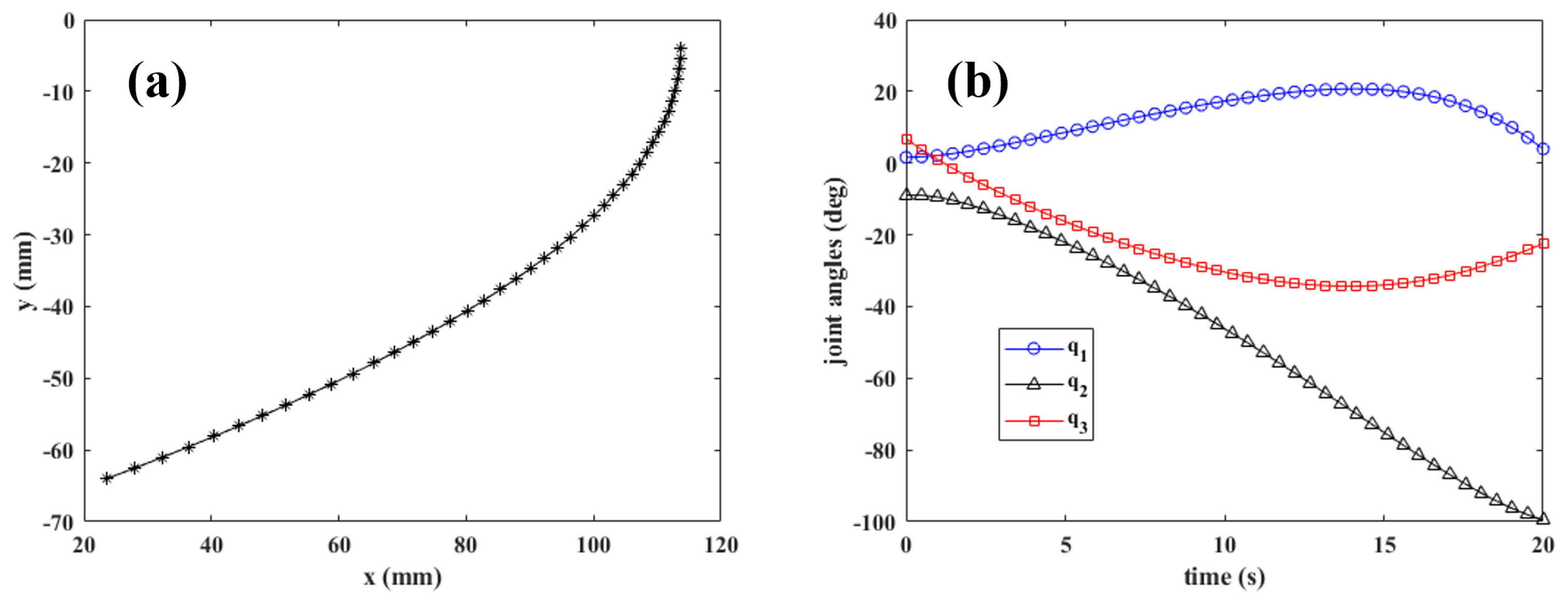
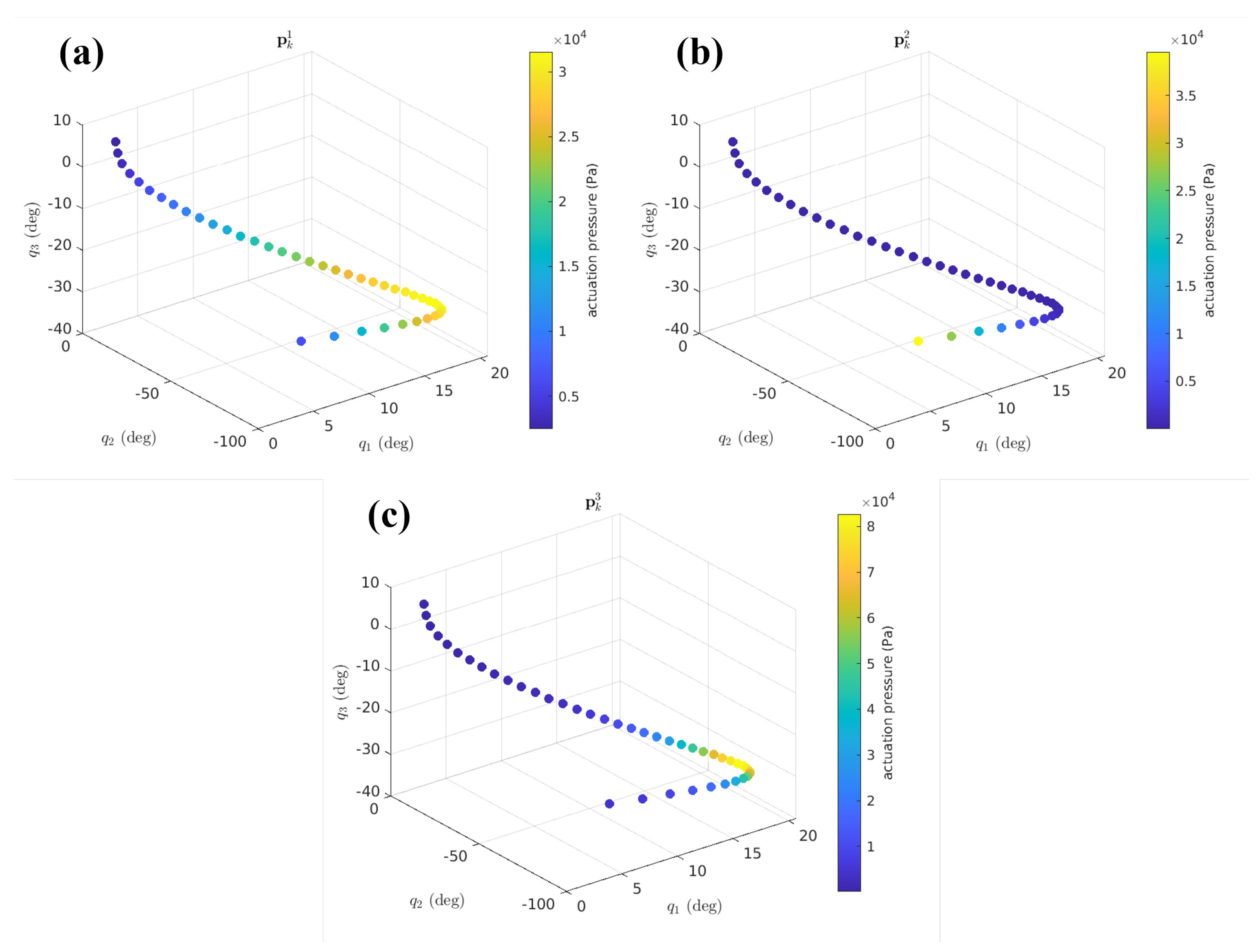
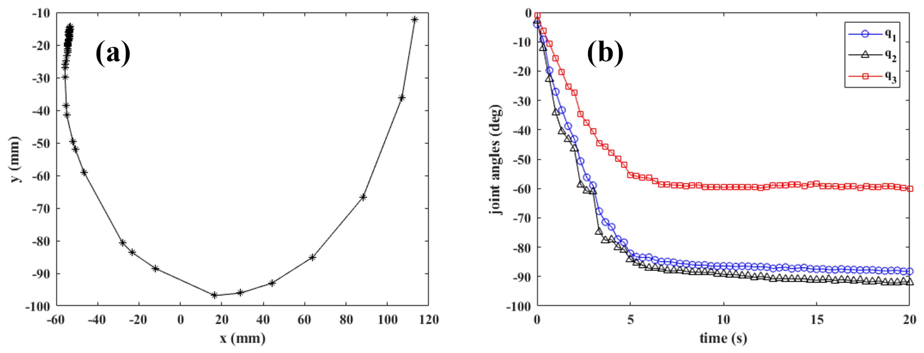
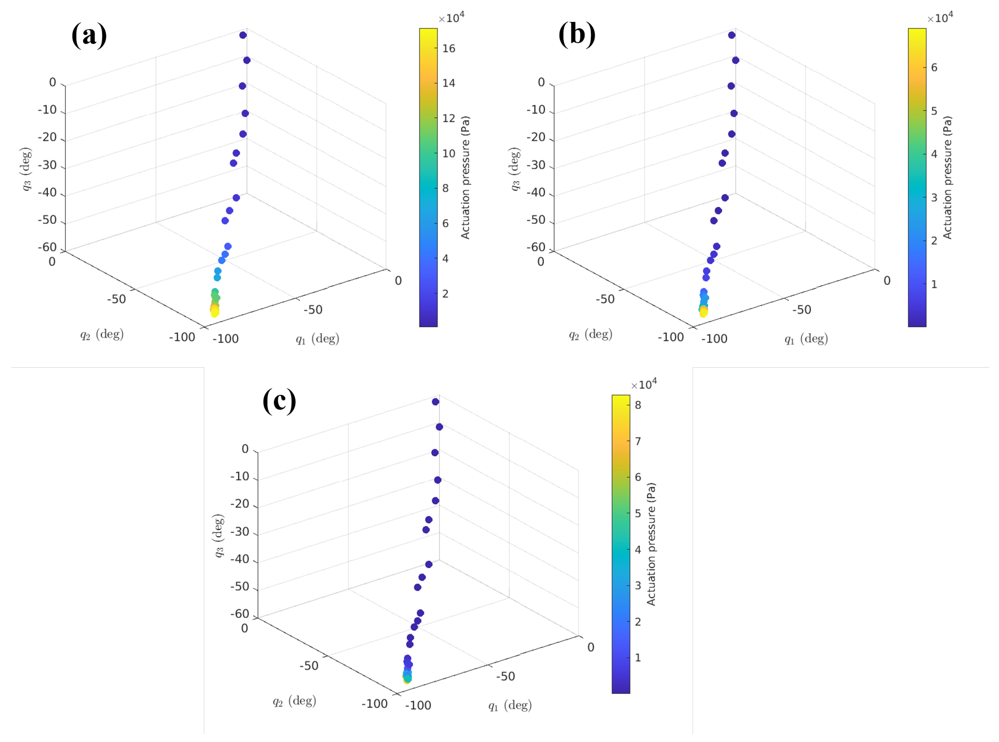
5.2. Trajectory Tracking of the Desired Fingertip Pose in Simulation

In this part, we theoretically examined the performance of the controller by following the desired fingertip pose for two different trajectories. Figure 8a shows the desired path ( x d and y d ) of the fingertip in Cartesian space, and the corresponding joint angles (motions) are depicted in Figure 8b. The path is arbitrary, but we considered a smooth curve function. Based on the latter, we can determine the desired orientation of the fingertip (i.e., θ d = q 1 + q 2 + q 3 ). The desired continuous trajectories ( x d , y d , and θ d ) are discretized into a series of discrete points, and the collective set of these values was used in Equation (19) to calculate the required actuation pressure at each soft actuator joint in order for the soft robotic exo-digit to move the human finger along the desired trajectories. The results are shown in Figure 9 for the varying values of the three joint angles. The color of each point in the plots represents the values of the pressure magnitude according to the provided color map. The results show that the control input solutions exist for tracking these specific trajectories in the configuration space of the soft robotic exo-digit with a trend of increasing pressure. The required theoretical pressure inputs are in the range of 0–30 kPa, 0–35kPa, and 0–80 kPa for MCP, PIP, and DIP joints, respectively, which are achievable by the control hardware system (Figure 4c).
In the second case, we used the experimental data of an actual human finger movement (flexion) to generate the desired trajectories, as shown in Figure 10a. The corresponding joint angles are determined based on the inverse kinematics of the human finger model, which will be used to calculate the desired orientation of the fingertip (i.e., θ d = q 1 + q 2 + q 3 ) for this case. Similar to the first case, these continuous functions were discretized into a series of way-points where the actuation pressure of each soft actuator was determined, as shown in Figure 11. The result shows the existence of the control solutions for following the second desired trajectory, while the magnitude of the required actuation pressure can be obtained from the provided color map. Note that the magnitude of the actuation pressures is higher compared to the first case as the desired trajectory requires more joint variation close to the full range of human finger range of motion. The maximum pressures (160 kPa) are beyond the range of our control hardware. Additionally, the rate of change of joint motion (joint velocities) is selected to be slow in order to be consistent with the quasi-static motion assumption. This is required by the therapeutic interventions for stroke patients as the fast movement of their fingers leads to spasticity, a condition in which there is an abnormal increase in muscle tone or stiffness of muscle [14].

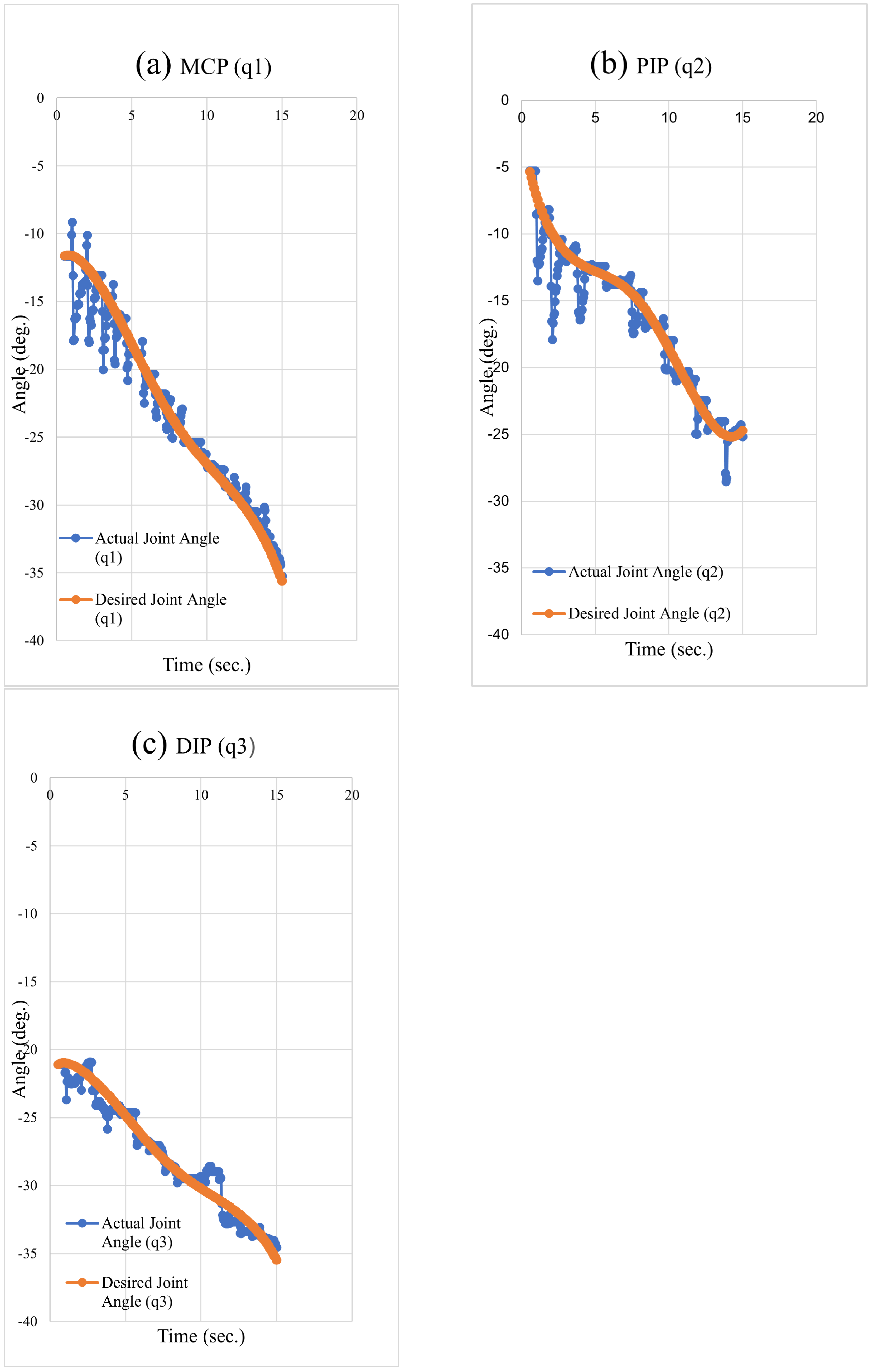
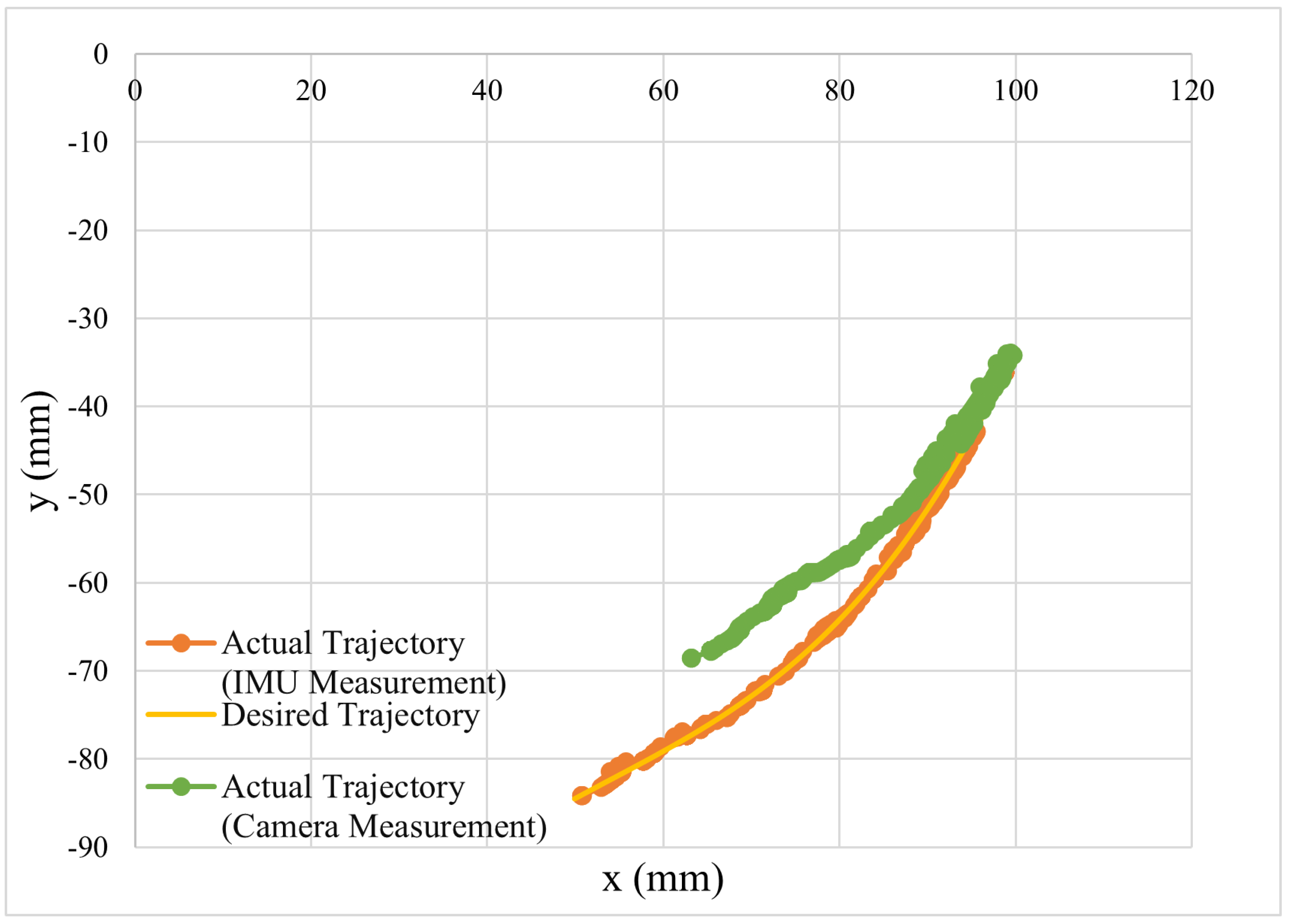
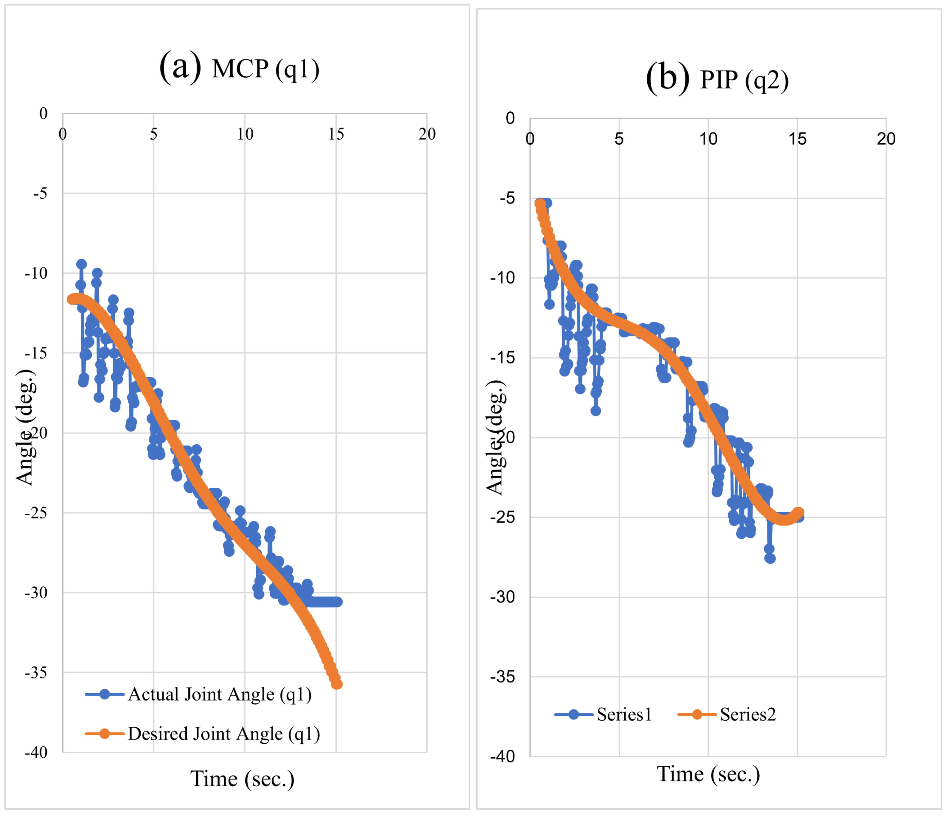
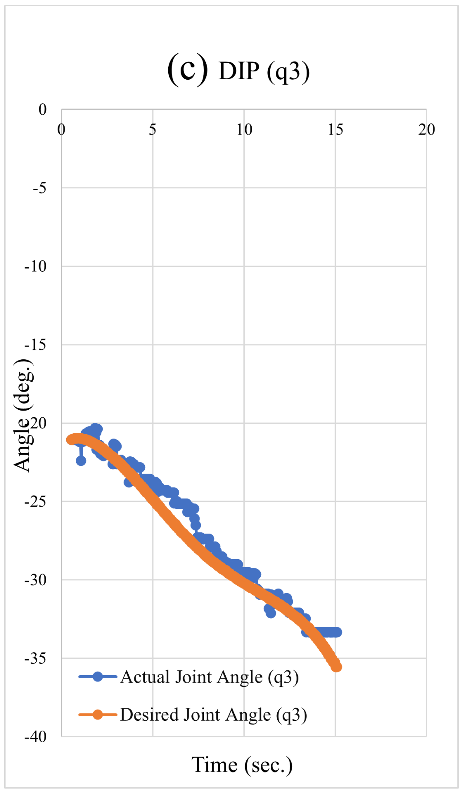
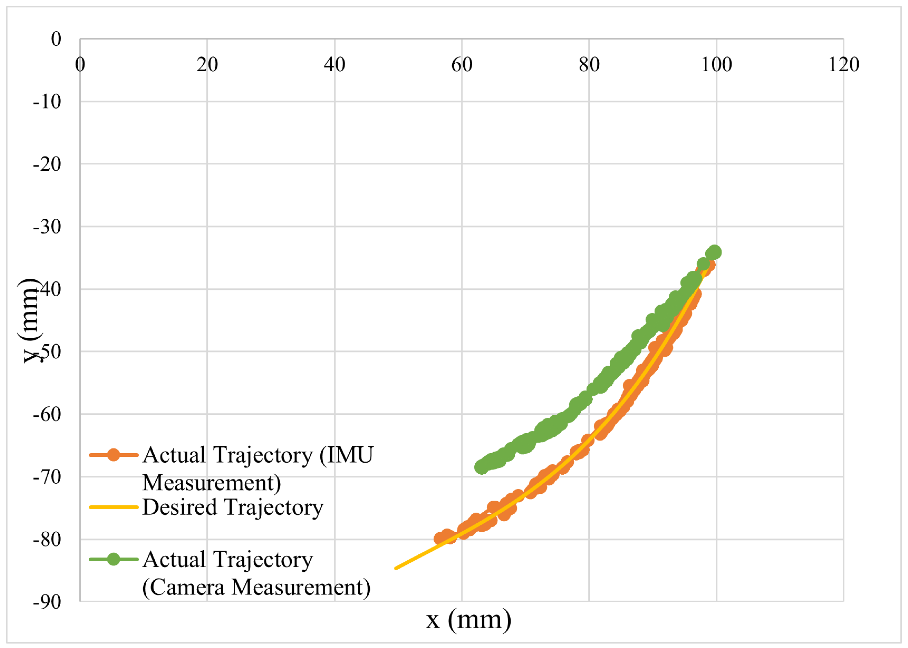
5.3. Trajectory Tracking of the Desired Fingertip Pose

A desired trajectory of a human fingertip is provided in the form of equations x = 0.002002 t 3 0.1278 t 2 1.848 t + 99.72 , y = 0.0002511 x 3 0.0407 x 2 + 2.728 x 150.5 , θ = 4 t 36 . With the given pose (x, y, θ ) of the fingertip, where each parameter varies with time, t, the three joint angles associated with the finger are calculated using inverse kinematics. The experimental setup includes an Arduino Mega 2560, four IMUs MPU6050 to measure the angular position of each joint in a human finger model, three MPRLS pressure sensors to measure the pressure buildup in three joints, three FA0520E three-way air valves to increase the pressure in each joint, three FA0520D two-way valves to release pressure from the joints, and six HM MOS modules for opening and closing the valves. An I2C Multiplexer (TCA9548A) is used to connect the pressure sensors and IMUs to the Arduino. The system is controlled by an Arduino program that adjusts the pressure applied to the joints to match the desired joint angles. The code starts by defining the output pins of the valves, reading the IMUs to obtain the joint angles, calculating the desired joint angles using inverse kinematics and comparing the actual and desired angles. If the desired angle is greater than the actual angle, the three-way valve of the joint opens to increase the pressure. If the desired angle is less than the actual angle, the two-way valve releases air from the joint, causing the red point in the fingertip, as shown in Figure 12, to move along the desired trajectory. Figure 13 depicts the joint angles for three joints (MCP, PIP, and DIP) and compares the actual angles with the desired angles for experiment-1. The outcomes reveal that the finger was able to accurately trace the desired joint angle for all three joints, with a root-mean-square error (RMSE) of 1.32, 1.46, and 0.86 degrees for each joint, respectively. The actual joint motions show an oscillating behavior around the desired joint trajectories. This behavior is due to the use of solenoid valves and a pulse width modulation (pwm) scheme for modulating the pressure of the soft actuators based on the presented control law. Replacing the solenoid valves with proportional valves, which operate with continuous opening and closing rather than pulsing, could help eliminate the chattering responses of the soft actuators. Additionally, the range of motion of the trajectory tracking can be increased by using a pressure sensor that measures in a higher range compared to the current sensors; the current pressure sensors in the control system measure in about the 0–70 kPa range, which led to a limited range of motion available for each soft actuator. Figure 14 demonstrates the expected and actual path of the fingertip as measured by both the IMU-based tracking and the camera. The IMU-based tracking uses the measured joint angles of the human finger and the forward kinematics equations to determine the fingertip pose. The picture confirms that the fingertip followed the desired path closely, with an RMSE of 7.49 mm in the x direction and 12.35 mm in the y direction for the camera measurement, 1.98 mm in the x direction, and 2.79 mm in the y direction for the IMU measurement. The deviation between the camera and IMU-based tracking is mainly due to the error of the camera software to accurately and consistently detect the exact location of the center of the marker attached to the fingertip.
The experiment was repeated for the second time, and the results for the joint angle and the tip trajectory are shown in Figure 15 and Figure 16, respectively. The obtained results confirm the repeatability of the control algorithm and the hardware. Once again, the actual joint angles followed the desired joint angles with a low RMSE of 1.63, 1.60, and 0.92 degrees for each joint, respectively. The RMSE for the camera measurement was 6.77 mm in the x direction and 11.15 mm in the y direction, while for the IMU measurement, it was 2.55 mm in the x direction and 2.71 mm in the y direction. Note that the resulting RMSE for IMU-based tracking and the camera-based tracking are very close and consistent between the two cases.
The Supplementary Materials folder contains the videos for both experiment-1 and experiment-2.

6. Conclusions

An algorithm for regulating the motion of a soft robotic exo-digit with three separate actuation joints that physically interact with a human finger is presented in this research using a quasi-static model-based approach. The motion of the soft exo-digit was controlled by regulating the position of the tip of the human finger model. The physical interaction between the soft exo-digit and a model of a human finger was developed using a quasi-static analytical model. The model was provided as a nonlinear discrete-time MIMO state-space representation for the control system design. The actuation pressure of a single soft actuator was used as the input, and a control input was created to linearize the input–output, with the output being the position of a human fingertip. The nonlinear discrete-time system for trajectory tracking control’s asymptotic stability is examined. The experimental test setup included a soft robotic exo-digit and a 3D-printed model of a human finger that was integrated with IMU sensors. For regulating the actuation pressure of the soft exo-digit, Arduino-based electro-pneumatic control hardware was developed. The controller’s performance was evaluated through simulated research and experimental testing for following various position trajectories similar to the human finger pose throughout daily tasks. The experiment was repeated twice, verifying the control algorithm’s repeatability. With a low average root-mean-square error of 2.27 mm in the x-direction, 2.75 mm in the y-direction, and 3.90 degrees in the orientation of the human finger distal link about the z-axis, the model-based controller was able to follow the desired trajectories.
In this study, we considered a model of human-robot interaction with simplifying assumptions such as linear torsional springs with a constant stiffness at the joint of the human finger model and the soft exo- digit’s soft actuation segments with a constant length and curvature. Moreover, model parameters uncertainties involved in both the soft robotic exo-digit and human finger model as well as variation of biomechanical parameters of the human finger model (i.e., joint stiffness and damping, rigid links’ inertia, and overall size), have not been considered. Apart from that, the human finger model was passive, so it only contributed a resistive force to the motions of the soft exo-digit. In contrast, the active participation of the human hand in daily activities is inevitable. These factors are ascribed to the study’s limitations. Considering all these limitations, future research will adopt a more realistic model of pHRI, develop adaptive robust hybrid force-position control laws to accommodate multi-task aspects (i.e., required simultaneous force and position controls) of the human hand fine motor motion, adaptability to variations in the biomechanics of the users, and robustness against uncertainties of the models.

Supplementary Materials

The following supporting information can be downloaded at: https://eltnmsu-my.sharepoint.com/:f:/g/personal/umme_nmsu_edu/ErcErdHzhZRLt9udiNXQZS0BXOc4xgKRPi6--QZKGFirgg?e=mJwm7y, Equation’s coefficient: Appendix.pdf; Video: experiment-1.mp4, experiment-2.mp4.

Author Contributions

Conceptualization, U.K.A. and M.H.-J.; methodology, U.K.A., K.S., and M.H.-J.; software, U.K.A. and K.S.; validation, U.K.A., K.S. and M.H.-J.; formal analysis, U.K.A.; investigation, U.K.A. and M.H.-J.; resources, M.H.-J.; data curation, U.K.A.; writing—original draft preparation, U.K.A.; writing—review and editing, M.H.-J. and K.S.; visualization, U.K.A.; supervision, M.H.-J.; project administration, M.H.-J.; funding acquisition, M.H.-J. All authors have read and agreed to the published version of the manuscript.

Funding

This research received no external funding.

Data Availability Statement

Access to data will be provided upon request.

Acknowledgments

The authors would like to thank Joshua Kirkland for helping with 3D-printing parts for the experimental test setup used in this study.

Conflicts of Interest

The authors declare no conflict of interest.

Abbreviations

The following abbreviations are used in this manuscript:
CPMContinuous passive motion
3DThree dimensional
DOFDegrees of freedom
pHRIPhysical human-robot interaction
SISOsingle-input single-output
MIMOmulti-input multi-output
MCPMetacarpophalangeal
DIPDistal Interphalangeal
PIPProximal Interphalangeal
kPAkilo Pascal
PWMPulse Width Modulation
IMUInertial Measurement Unit
RMSERoot mean square error

Appendix A. Lie Derivatives

Appendix A.1. Invertibility of L g i h ( x k )

The Lie derivative terms are presented here
L g 1 h ( x k ) = A p 1 l 1 x 1 2 r p 1 σ 1 2 l 2 s 12 + 2 l 1 s 1 + l 3 s 123 2 l 2 c 12 + 2 l 1 c 1 + l 3 c 123 1
where
σ 1 = k h 1 l ^ 1 + d 1 x 1 2 l ^ 1 c 1
L g 2 h ( x k ) = 1 k 2 σ 3 σ 5 A p 2 x 1 2 x 3 r p 2 σ 1 + 2 l 1 s 1 + l 3 σ 8 σ 4 k h 2 σ 5 A p 2 l 2 x 1 2 x 2 x 3 r p 2 σ 1 + l 3 σ 8 σ 3 A p 2 l 2 x 1 2 x 2 x 3 r p 2 σ 2 + l 3 σ 7 σ 3 A p 2 x 1 2 x 3 r p 2 σ 2 + 2 l 1 c 1 + l 3 σ 7 σ 4 k 2 σ 5 A p 2 l 2 x 1 2 x 2 x 3 r p 2 σ 3 A p 2 x 1 2 x 3 r p 2 σ 4 k h 2 σ 5
where σ 1 ,..., σ 8 are given in the appendix file of the Supplementary Materials folder.
L g 3 h ( x k ) = A p 3 r p 3 x 3 2 k 3 k 2 x 2 σ 9 σ 8 σ 5 l 3 2 σ 11 k 2 σ 8 σ 5 σ 1 + l 3 σ 11 σ 4 k 3 σ 5 σ 1 + 2 l 1 s 1 + l 3 σ 11 σ 3 k 3 k 2 σ 9 σ 8 l 3 2 σ 10 k 2 σ 8 σ 5 x 2 + σ 2 + l 3 σ 10 σ 4 k 3 σ 5 x 2 + σ 2 + 2 l 1 c 1 + l 3 σ 10 σ 3 k 3 k 2 x 2 σ 9 σ 8 l 3 k 2 x 2 σ 8 σ 5 + σ 4 k 3 σ 5 + σ 3 k 3 k 2 x 2 σ 9 σ 8
where σ 1 ,..., σ 8 are given in the appendix file of the Supplementary Materials folder.
The determinant of L G h ( x k ) is provided here, and the values of the determinant are obtained for the configuration space of the soft robotic exo-digit as illustrated in Figure A1 where the pseudo joint bending angles varied in the range of motion of the human finger joints. The results are presented for varying values of q 1 , while the surface demonstrates the variation of the determinant for variation q 2 and q 3 . Excluding the q 2 = 0 , which is the singularity of L G h ( x k ) , the determinant stayed finite and there is a trend of increasing values towards the upper limit of q 2 and q 3 for the range of 0 < q 1 50 . As shown in Figure A1, after q 1 larger than 60 , there is a discontinuity in the determinant manifold towards the upper limit q 2 and q 3 . The discontinuity is displayed on the 2D projection of the manifold in Figure A2. Despite the discontinuity,
L G h ( x k ) = 4 A p 1 A p 2 A p 3 r p 1 r p 2 r p 3 l 1 2 l 2 2 l 3 x 1 4 x 2 x 3 3 s 1 k 1 k 2 k 3 σ 4 σ 5 x 1 2 ( x 3 c 1 l ^ 2 σ 9 + x 2 l ^ 3 σ 7 ) + x 2 x 3 ( l ^ 1 σ 6 + x 1 ( l ^ 1 σ 8 + x 1 σ 3 ) )
where σ 1 ,..., σ 9 are given in the appendix file of the Supplementary Materials folder.
Figure A1. Variation of L G h ( x k ) of with respect to q 2 and q 3 for different values of q 1 .
Automation 04 00011 g0a1
Figure A2. 2D plot of surface plots in Figure A1, the red arrow shows the discontinuity in L G h ( x k ) for that region of the configuration space.
Automation 04 00011 g0a2

Appendix A.2. Symbolic Equations of L f h ( x k )

L f h ( x k ) = l 3 2 x 3 2 τ s 3 σ 11 k 3 σ 9 q 3 σ 1 + l 3 σ 11 σ 4 k 2 q 2 σ 9 σ 8 σ 1 + 2 l 1 s 1 + l 3 σ 11 σ 3 σ 5 l 3 2 q 3 2 τ s 3 σ 10 k 3 σ 9 + q 3 σ 2 + l 3 σ 10 σ 4 k 2 q 2 σ 9 σ 8 + σ 2 + 2 l 1 c 1 + l 3 σ 10 σ 3 σ 5 l 3 q 3 2 τ s 3 k 3 σ 9 + σ 3 σ 5 + q 3 σ 4 k 2 q 2 σ 9 σ 8
where σ 1 ,..., σ 11 are given in the appendix file of the Supplementary Materials folder.

References

  1. Feigin, V.L.; Roth, G.A.; Naghavi, M.; Parmar, P.; Krishnamurthi, R.; Chugh, S.; Mensah, G.A.; Norrving, B.; Shiue, I.; Ng, M.; et al. Global burden of stroke and risk factors in 188 countries, during 1990-2013: A systematic analysis for the Global Burden of Disease Study 2013. Lancet Neurol. 2016, 15, 913–924. [Google Scholar] [CrossRef] [PubMed]
  2. Sanjuan, J.; Castillo, A.D.; Padilla, M.A.; Quintero, M.C.; Gutierrez, E.; Sampayo, I.P.; Hernandez, J.R.; Rahman, M.H. Cable driven exoskeleton for upper-limb rehabilitation: A design review. Robot. Auton. Syst. 2020, 126, 103445. [Google Scholar] [CrossRef]
  3. Dobkin, B.H. Strategies for stroke rehabilitation. Lancet Neurol. 2004, 3, 528–536. [Google Scholar] [CrossRef] [PubMed]
  4. Maciejasz, P.; Eschweiler, J.; Gerlach-Hahn, K.; Jansen-Troy, A.; Leonhardt, S. A survey on robotic devices for upper limb rehabilitation. J. Neuroeng. Rehabil. 2014, 11, 3. [Google Scholar] [CrossRef]
  5. Walsh, C. Human-in-the-loop development of soft wearable robots. Nat. Rev. Mater. 2018, 3, 78–80. [Google Scholar] [CrossRef]
  6. Haghshenas-Jaryani, M.; Carrigan, W.; Wijesundara, M.B.; Patterson, R.M.; Bugnariu, N.; Niacaris, T. Kinematic Study of a Soft-and-Rigid Robotic Digit for Rehabilitation and Assistive Applications. In Proceedings of the ASME 2016 International Design Engineering Technical Conferences and Computers and Information in Engineering Conference, Charlotte, NC, USA, 21–24 August 2016; American Society of Mechanical Engineers Digital Collection: New York, NY, USA, 2016. [Google Scholar]
  7. Rus, D.; Tolley, M.T. Design, fabrication and control of soft robots. Nature 2015, 521, 467. [Google Scholar] [CrossRef]
  8. Polygerinos, P.; Correll, N.; Morin, S.A.; Mosadegh, B.; Onal, C.D.; Petersen, K.; Cianchetti, M.; Tolley, M.T.; Shepherd, R.F. Soft robotics: Review of fluid-driven intrinsically soft devices; manufacturing, sensing, control, and applications in human-robot interaction. Adv. Eng. Mater. 2017, 19, 1700016. [Google Scholar] [CrossRef]
  9. Polygerinos, P.; Wang, Z.; Galloway, K.C.; Wood, R.J.; Walsh, C.J. Soft robotic glove for combined assistance and at-home rehabilitation. Robot. Auton. Syst. 2015, 73, 135–143. [Google Scholar] [CrossRef]
  10. Haghshenas-Jaryani, M.; Carrigan, W.; Nothnagle, C.; Wijesundara, M.B. Sensorized soft robotic glove for continuous passive motion therapy. In Proceedings of the 2016 6th IEEE International Conference on Biomedical Robotics and Biomechatronics (BioRob), Singapore, 26–29 June 2016; IEEE: Piscataway, NJ, USA, 2016; pp. 815–820. [Google Scholar]
  11. Haghshenas-Jaryani, M.; Nothnagle, C.; Patterson, R.M.; Bugnariu, N.; Wijesundara, M.B. Soft robotic rehabilitation exoskeleton (rehab glove) for hand therapy. In Proceedings of the ASME 2017 International Design Engineering Technical Conferences and Computers and Information in Engineering Conference, Cleveland, OH, USA, 6–9 August 2017; American Society of Mechanical Engineers Digital Collection: New York, NY, USA, 2017. [Google Scholar]
  12. Chu, C.Y.; Patterson, R.M. Soft robotic devices for hand rehabilitation and assistance: A narrative review. J. Neuroeng. Rehabil. 2018, 15, 9. [Google Scholar] [CrossRef]
  13. Shahid, T.; Gouwanda, D.; Nurzaman, S.G.; Gopalai, A.A. Moving toward soft robotics: A decade review of the design of hand exoskeletons. Biomimetics 2018, 3, 17. [Google Scholar] [CrossRef]
  14. Haghshenas-Jaryani, M.; Pande, C.; Wijesundara, B.M. Soft Robotic Bilateral Hand Rehabilitation System for Fine Motor Learning. In Proceedings of the 2019 IEEE 16th International Conference on Rehabilitation Robotics (ICORR), Toronto, ON, Canada, 24–28 June 2019; IEEE: Piscataway, NJ, USA, 2019; pp. 337–342. [Google Scholar]
  15. Kadowaki, Y.; Noritsugu, T.; Takaiwa, M.; Sasaki, D.; Kato, M. Development of soft power-assist glove and control based on human intent. J. Robot. Mechatron. 2011, 23, 281–291. [Google Scholar] [CrossRef]
  16. Thalman, C.; Artemiadis, P. A review of soft wearable robots that provide active assistance: Trends, common actuation methods, fabrication, and applications. Wearable Technol. 2020, 1, e3. [Google Scholar] [CrossRef]
  17. Iqbal, J.; Khan, H.; Tsagarakis, N.G.; Caldwell, D.G. A novel exoskeleton robotic system for hand rehabilitation–conceptualization to prototyping. Biocybern. Biomed. Eng. 2014, 34, 79–89. [Google Scholar] [CrossRef]
  18. Lum, P.S.; Godfrey, S.B.; Brokaw, E.B.; Holley, R.J.; Nichols, D. Robotic approaches for rehabilitation of hand function after stroke. Am. J. Phys. Med. Rehabil. 2012, 91, S242–S254. [Google Scholar] [CrossRef]
  19. Heo, P.; Gu, G.M.; Lee, S.J.; Rhee, K.; Kim, J. Current hand exoskeleton technologies for rehabilitation and assistive engineering. Int. J. Precis. Eng. Manuf. 2012, 13, 807–824. [Google Scholar] [CrossRef]
  20. Rose, C.G.; O’Malley, M.K. Hybrid rigid-soft hand exoskeleton to assist functional dexterity. IEEE Robot. Autom. Lett. 2018, 4, 73–80. [Google Scholar] [CrossRef]
  21. Noritsugu, T.; Yamamoto, H.; Sasakil, D.; Takaiwa, M. Wearable power assist device for hand grasping using pneumatic artificial rubber muscle. In Proceedings of the SICE 2004 Annual Conference, Sapporo, Japan, 4–6 August 2004; IEEE: Piscataway, NJ, USA, 2004; Volume 1, pp. 420–425. [Google Scholar]
  22. Polygerinos, P.; Lyne, S.; Wang, Z.; Nicolini, L.F.; Mosadegh, B.; Whitesides, G.M.; Walsh, C.J. Towards a soft pneumatic glove for hand rehabilitation. In Proceedings of the 2013 IEEE/RSJ International Conference on Intelligent Robots and Systems, Tokyo, Japan, 3–7 November 2013; IEEE: Piscataway, NJ, USA, 2013; pp. 1512–1517. [Google Scholar]
  23. Yap, H.K.; Ang, B.W.; Lim, J.H.; Goh, J.C.; Yeow, C.H. A fabric-regulated soft robotic glove with user intent detection using EMG and RFID for hand assistive application. In Proceedings of the 2016 IEEE International Conference on Robotics and Automation (ICRA), Stockholm, Sweden, 16–21 May 2016; IEEE: Piscataway, NJ, USA, 2016; pp. 3537–3542. [Google Scholar]
  24. Noritsugu, T.; Takaiwa, M.; Sasaki, D. Power assist wear driven with pneumatic rubber artificial muscles. In Proceedings of the 2008 15th International Conference on Mechatronics and Machine Vision in Practice, Auckland, New Zealand, 2–4 December 2008; IEEE: Piscataway, NJ, USA, 2008; pp. 539–544. [Google Scholar]
  25. Cappello, L.; Meyer, J.T.; Galloway, K.C.; Peisner, J.D.; Granberry, R.; Wagner, D.A.; Engelhardt, S.; Paganoni, S.; Walsh, C.J. Assisting hand function after spinal cord injury with a fabric-based soft robotic glove. J. Neuroeng. Rehabil. 2018, 15, 59. [Google Scholar] [CrossRef]
  26. Zhao, H.; Jalving, J.; Huang, R.; Knepper, R.; Ruina, A.; Shepherd, R. A helping hand: Soft orthosis with integrated optical strain sensors and EMG control. IEEE Robot. Autom. Mag. 2016, 23, 55–64. [Google Scholar] [CrossRef]
  27. Zhang, F.; Lin, L.; Yang, L.; Fu, Y. Variable impedance control of finger exoskeleton for hand rehabilitation following stroke. Ind. Robot. Int. J. Robot. Res. Appl. 2019, 47, 23–32. [Google Scholar] [CrossRef]
  28. Shiota, K.; Kokubu, S.; Tarvainen, T.V.; Sekine, M.; Kita, K.; Huang, S.Y.; Yu, W. Enhanced Kapandji test evaluation of a soft robotic thumb rehabilitation device by developing a fiber-reinforced elastomer-actuator based 5-digit assist system. Robot. Auton. Syst. 2019, 111, 20–30. [Google Scholar] [CrossRef]
  29. Jiang, Y.; Chen, D.; Liu, P.; Jiao, X.; Ping, Z.; Xu, Z.; Li, J.; Xu, Y. Fishbone-inspired soft robotic glove for hand rehabilitation with multi-degrees-of-freedom. In Proceedings of the 2018 IEEE International Conference on Soft Robotics (RoboSoft), Livorno, Italy, 24–28 April 2018; IEEE: Piscataway, NJ, USA, 2018; pp. 394–399. [Google Scholar]
  30. Heung, K.H.; Tong, R.K.; Lau, A.T.; Li, Z. Robotic glove with soft-elastic composite actuators for assisting activities of daily living. Soft Robot. 2019, 6, 289–304. [Google Scholar] [CrossRef] [PubMed]
  31. Popov, D.; Gaponov, I.; Ryu, J.H. Portable exoskeleton glove with soft structure for hand assistance in activities of daily living. IEEE/ASME Trans. Mechatron. 2016, 22, 865–875. [Google Scholar] [CrossRef]
  32. In, H.; Kang, B.B.; Sin, M.; Cho, K.J. Exo-glove: A wearable robot for the hand with a soft tendon routing system. IEEE Robot. Autom. Mag. 2015, 22, 97–105. [Google Scholar] [CrossRef]
  33. Kang, B.B.; Choi, H.; Lee, H.; Cho, K.J. Exo-Glove Poly II: A Polymer-Based Soft Wearable Robot for the Hand with a Tendon-Driven Actuation System. Soft Robot. 2019, 6, 214–227. [Google Scholar] [CrossRef]
  34. Haghshenas-Jaryani, M.; Patterson, R.M.; Bugnariu, N.; Wijesundara, M.B. A pilot study on the design and validation of a hybrid exoskeleton robotic device for hand rehabilitation. J. Hand Ther. 2020, 33, 198–208. [Google Scholar] [CrossRef]
  35. Yun, S.S.; Kang, B.B.; Cho, K.J. Exo-glove PM: An easily customizable modularized pneumatic assistive glove. IEEE Robot. Autom. Lett. 2017, 2, 1725–1732. [Google Scholar] [CrossRef]
  36. Gerez, L.; Gao, G.; Dwivedi, A.; Liarokapis, M. A Hybrid, Wearable Exoskeleton Glove Equipped With Variable Stiffness Joints, Abduction Capabilities, and a Telescopic Thumb. IEEE Access 2020, 8, 173345–173358. [Google Scholar] [CrossRef]
  37. Kang, B.B.; Lee, H.; In, H.; Jeong, U.; Chung, J.; Cho, K.J. Development of a polymer-based tendon-driven wearable robotic hand. In Proceedings of the 2016 IEEE International Conference on Robotics and Automation (ICRA), Stockholm, Sweden, 16–21 May 2016; IEEE: Piscataway, NJ, USA, 2016; pp. 3750–3755. [Google Scholar]
  38. Jeong, U.; In, H.; Lee, H.; Kang, B.B.; Cho, K. Investigation on the control strategy of soft wearable robotic hand with slack enabling tendon actuator. In Proceedings of the 2015 IEEE International Conference on Robotics and Automation (ICRA), Seattle, WA, USA, 26–30 May 2015; pp. 5004–5009. [Google Scholar]
  39. Nilsson, M.; Ingvast, J.; Wikander, J.; von Holst, H. The Soft Extra Muscle system for improving the grasping capability in neurological rehabilitation. In Proceedings of the 2012 IEEE-EMBS Conference on Biomedical Engineering and Sciences, Langkawi, Malaysia, 17–19 December 2012; IEEE: Piscataway, NJ, USA, 2012; pp. 412–417. [Google Scholar]
  40. Lee, S.W.; Landers, K.A.; Park, H.S. Development of a biomimetic hand exotendon device (BiomHED) for restoration of functional hand movement post-stroke. IEEE Trans. Neural Syst. Rehabil. Eng. 2014, 22, 886–898. [Google Scholar] [CrossRef]
  41. Borboni, A.; Mor, M.; Faglia, R. Gloreha—Hand robotic rehabilitation: Design, mechanical model, and experiments. J. Dyn. Syst. Meas. Control 2016, 138, 111003. [Google Scholar] [CrossRef]
  42. Nycz, C.J.; Delph, M.A.; Fischer, G.S. Modeling and design of a tendon actuated soft robotic exoskeleton for hemiparetic upper limb rehabilitation. In Proceedings of the 2015 37th Annual International Conference of the IEEE Engineering in Medicine and Biology Society (EMBC), Milan, Italy, 25–29 August 2015; IEEE: Piscataway, NJ, USA, 2015; pp. 3889–3892. [Google Scholar]
  43. Meeker, C.; Park, S.; Bishop, L.; Stein, J.; Ciocarlie, M. EMG pattern classification to control a hand orthosis for functional grasp assistance after stroke. In Proceedings of the 2017 International Conference on Rehabilitation Robotics (ICORR), London, UK, 17–20 July 2017; IEEE: Piscataway, NJ, USA, 2017; pp. 1203–1210. [Google Scholar]
  44. Park, S.; Weber, L.; Bishop, L.; Stein, J.; Ciocarlie, M. Design and development of effective transmission mechanisms on a tendon driven hand orthosis for stroke patients. In Proceedings of the 2018 IEEE International Conference on Robotics and Automation (ICRA), Brisbane, Australia, 21–25 May 2018; IEEE: Piscataway, NJ, USA, 2018; pp. 2281–2287. [Google Scholar]
  45. Xiloyannis, M.; Cappello, L.; Binh, K.D.; Antuvan, C.W.; Masia, L. Preliminary design and control of a soft exosuit for assisting elbow movements and hand grasping in activities of daily living. J. Rehabil. Assist. Technol. Eng. 2017, 4, 2055668316680315. [Google Scholar] [CrossRef]
  46. Grosu, S.; Rodriguez-Guerrero, C.; Grosu, V.; Vanderborght, B.; Lefeber, D. Evaluation and Analysis of Push-Pull Cable Actuation System Used for Powered Orthoses. Front. Robot. AI 2018, 5, 105. [Google Scholar] [CrossRef]
  47. Haghshenas-Jaryani, M.; Carrigan, W.; Wijesundara, M.B. Design and Development of a Novel Soft-and-Rigid Hybrid Actuator System for Robotic Applications. In Proceedings of the ASME 2015 International Design Engineering Technical Conferences and Computers and Information in Engineering Conference, Boston, MA, USA, 2–5 August 2015; American Society of Mechanical Engineers: New York, NY, USA, 2015; Volume 5A, pp. V05AT08A047–V05AT08A053. [Google Scholar]
  48. Kadivar, Z.; Beck, C.E.; Rovekamp, R.N.; O’Malley, M.K.; Joyce, C.A. On the efficacy of isolating shoulder and elbow movements with a soft, portable, and wearable robotic device. In Wearable Robotics: Challenges and Trends; Springer: Berlin/Heidelberg, Germany, 2017; pp. 89–93. [Google Scholar]
  49. Marchese, A.D.; Tedrake, R.; Rus, D. Dynamics and trajectory optimization for a soft spatial fluidic elastomer manipulator. In Proceedings of the 2015 IEEE International Conference on Robotics and Automation (ICRA), Seattle, WA, USA, 26–30 May 2015; pp. 2528–2535. [Google Scholar]
  50. Santina, C.D.; Katzschmann, R.K.; Biechi, A.; Rus, D. Dynamic control of soft robots interacting with the environment. In Proceedings of the 2018 IEEE International Conference on Soft Robotics (RoboSoft), Livorno, Italy, 24–28 April 2018; pp. 46–53. [Google Scholar] [CrossRef]
  51. George Thuruthel, T.; Ansari, Y.; Falotico, E.; Laschi, C. Control strategies for soft robotic manipulators: A survey. Soft Robot. 2018, 5, 149–163. [Google Scholar] [CrossRef]
  52. Tang, Z.Q.; Heung, H.L.; Shi, X.Q.; Tong, K.Y.; Li, Z. Probabilistic Model-Based Learning Control of a Soft Pneumatic Glove for Hand Rehabilitation. IEEE Trans. Biomed. Eng. 2022, 69, 1016–1028. [Google Scholar] [CrossRef]
  53. Tiboni, M.; Amici, C. Soft Gloves: A Review on Recent Developments in Actuation, Sensing, Control and Applications. Actuators 2022, 11, 232. [Google Scholar] [CrossRef]
  54. du Plessis, T.; Djouani, K.; Oosthuizen, C. A review of active hand exoskeletons for rehabilitation and assistance. Robotics 2021, 10, 40. [Google Scholar] [CrossRef]
  55. Farrow, N.; Correll, N. A soft pneumatic actuator that can sense grasp and touch. In Proceedings of the 2015 IEEE/RSJ International Conference on Intelligent Robots and Systems (IROS), Hamburg, Germany, 28 September–2 October 2015; IEEE: Piscataway, NJ, USA, 2015; pp. 2317–2323. [Google Scholar]
  56. Bilodeau, R.A.; White, E.L.; Kramer, R.K. Monolithic fabrication of sensors and actuators in a soft robotic gripper. In Proceedings of the 2015 IEEE/RSJ International Conference on Intelligent Robots and Systems (IROS), Hamburg, Germany, 28 September–2 October 2015; IEEE: Piscataway, NJ, USA, 2015; pp. 2324–2329. [Google Scholar]
  57. Case, J.C.; White, E.L.; Kramer, R.K. Sensor enabled closed-loop bending control of soft beams. Smart Mater. Struct. 2016, 25, 045018. [Google Scholar] [CrossRef]
  58. Correll, N.; Önal, Ç.D.; Liang, H.; Schoenfeld, E.; Rus, D. Soft autonomous materials—Using active elasticity and embedded distributed computation. In Proceedings of the Experimental Robotics, Bali, Indonesia, 5–10 December 2014; Springer: New York, NY, USA, 2014; pp. 227–240. [Google Scholar]
  59. Ha, J.; Kim, D.; Jo, S. Use of deep learning for position estimation and control of soft glove. In Proceedings of the 2018 18th International Conference on Control, Automation and Systems (ICCAS), PyeongChang, Republic of Korea, 17–20 October 2018; IEEE: Piscataway, NJ, USA, 2018; pp. 570–574. [Google Scholar]
  60. Jones, C.L.; Wang, F.; Morrison, R.; Sarkar, N.; Kamper, D.G. Design and development of the cable actuated finger exoskeleton for hand rehabilitation following stroke. IEEE/ASME Trans. Mechatron. 2012, 19, 131–140. [Google Scholar] [CrossRef]
  61. Kaneishi, D.; Matthew, R.P.; Leu, J.E.; O’Donnell, J.; Zhang, B.; Tomizuka, M.; Stuart, H. Hybrid control interface of a semi-soft assistive glove for people with spinal cord injuries. In Proceedings of the 2019 IEEE 16th International Conference on Rehabilitation Robotics (ICORR), Toronto, ON, Canada, 24–28 June 2019; IEEE: Piscataway, NJ, USA, 2019; pp. 132–138. [Google Scholar]
  62. Sierotowicz, M.; Lotti, N.; Nell, L.; Missiroli, F.; Alicea, R.; Zhang, X.; Xiloyannis, M.; Rupp, R.; Papp, E.; Krzywinski, J.; et al. EMG-Driven Machine Learning Control of a Soft Glove for Grasping Assistance and Rehabilitation. IEEE Robot. Autom. Lett. 2022, 7, 1566–1573. [Google Scholar] [CrossRef]
  63. Haghshenas-Jaryani, M. Adaptive Quasi-Static Motion Control of a Soft Robotic Exo-Digit in physical Human-Wearable-Soft-Robot-Interaction. In Proceedings of the IEEE 18th International Conference on Automation Science and Engineering (CASE), Mexico City, Mexico, 20–24 August 2022. [Google Scholar]
  64. Kamper, D.G.; Rymer, W.Z. Quantitative features of the stretch response of extrinsic finger muscles in hemiparetic stroke. Muscle & Nerve Off. J. Am. Assoc. Electrodiagn. Med. 2000, 23, 954–961. [Google Scholar]
  65. Kamper, D.; Rymer, W.Z. Impairment of voluntary control of finger motion following stroke: Role of inappropriate muscle coactivation. Muscle Nerve Off. J. Am. Assoc. Electrodiagn. Med. 2001, 24, 673–681. [Google Scholar] [CrossRef]
  66. Polygerinos, P.; Wang, Z.; Overvelde, J.T.; Galloway, K.C.; Wood, R.J.; Bertoldi, K.; Walsh, C.J. Modeling of soft fiber-reinforced bending actuators. IEEE Trans. Robot. 2015, 31, 778–789. [Google Scholar] [CrossRef]
  67. Nikolov, S.; Kotev, V.; Kostadinov, K.; Wang, F.; Liang, C.; Tian, Y. Model-based design optimization of soft fiber-reinforced bending actuators. In Proceedings of the 2016 IEEE International Conference on Manipulation, Manufacturing and Measurement on the Nanoscale (3M-NANO), Chongqing, China, 18–22 July 2016; IEEE: Piscataway, NJ, USA, 2016; pp. 136–140. [Google Scholar]
  68. Haghshenas-Jaryani, M.; Wijesundara, M.B. A Quasi-Static Model for Studying Physical Interaction Between a Soft Robotic Digit and a Human Finger. In Proceedings of the ASME 2018 International Design Engineering Technical Conferences and Computers and Information in Engineering Conference, Quebec City, QC, Canada, 26–29 August 2018; American Society of Mechanical Engineers Digital Collection: New York, NY, USA, 2018. [Google Scholar]
  69. Haghshenas-Jaryani, M.; Manvar, M.; Wijesundara, M.B. Torque Characterization of a Novel Pneumatic Soft-and-Rigid Hybrid Actuator. In Proceedings of the ASME 2017 Dynamic Systems and Control Conference, Tysons Corner, VA, USA, 11–13 October 2017; American Society of Mechanical Engineers Digital Collection: New York, NY, USA, 2017. [Google Scholar]
  70. Haghshenas-Jaryani, M. Quasi-Static Model-based Control of Human-Soft-Robot Interaction for Assisted Hand Motion. In Proceedings of the 2020 8th IEEE RAS/EMBS International Conference for Biomedical Robotics and Biomechatronics (BioRob), New York City, NY, USA, 29 November–1 December 2020; pp. 370–375. [Google Scholar] [CrossRef]
  71. Khalil, H.K. Nonlinear Control, 3rd ed.; Pearson: New York, NY, USA, 2015. [Google Scholar]
  72. Isidori, A. Nonlinear Control Systems: An Introduction; Springer: Berlin/Heidelberg, Germany, 1985. [Google Scholar]
  73. Jayaraman, G.; Chizeck, H.J. Feedback linearization of discrete-time systems. In Proceedings of the 32nd IEEE Conference on Decision and Control, San Antonio, TX, USA, 15–17 December 1993; Volume 4, pp. 2972–2977. [Google Scholar] [CrossRef]
Figure 1. (a) Physical setup of a soft robotic exo-digit and a 3D-printed human finger model and (b) a schematic of the soft robotic digit interacting with a human finger.
Automation 04 00011 g001
Figure 2. Workspace of the human finger model and the soft exo-digit.
Automation 04 00011 g002
Figure 3. Feedback linearization control block diagram for pressure-based pose control.
Automation 04 00011 g003
Figure 4. (a) Control system block diagram for pressure-based pose control and (b) schematics of the electro-pneumatic diagram with control components and (c) the actual control setup where each component labeled according to the corresponding number in Table 1.
Automation 04 00011 g004
Figure 5. Variation of the pressure of the first soft actuator segment with respect to the configuration space of the soft robotic exo-digit.
Automation 04 00011 g005
Figure 6. Variation of the pressure of the second soft actuator segment with respect to the configuration space of the soft robotic exo-digit.
Automation 04 00011 g006
Figure 7. Variation of the pressure of the third soft actuator segment with respect to the configuration space of the soft robotic exo-digit.
Automation 04 00011 g007
Figure 8. (a) The first desired trajectory of the tip of the human finger in the Cartesian space and (b) corresponding joint angles.
Automation 04 00011 g008
Figure 9. Variation of the controlled pressure of (a) the first soft actuator segment, (b) the second soft actuator segment and (c) the third soft actuator segment with respect to the configuration space of the soft robotic exo-digit in following the first desired trajectory (see Figure 8).
Automation 04 00011 g009
Figure 10. (a) The second desired trajectory of the tip of the human finger in the Cartesian space and (b) corresponding joint angles.
Automation 04 00011 g010
Figure 11. Variation of the controlled pressure of (a) the first soft actuator segment, (b) the second soft actuator segment and (c) the third soft actuator segment with respect to the configuration space of the soft robotic exo-digit in following the second desired trajectory (see Figure 10).
Automation 04 00011 g011
Figure 12. Close-up picture of the human finger model in the experimental setup.
Automation 04 00011 g012
Figure 13. The actual and desired joint angle of (a) MCP, (b) PIP, (c) DIP of experiment-1.
Automation 04 00011 g013
Figure 14. The actual and desired trajectory of the fingertip of experiment-1.
Automation 04 00011 g014
Figure 15. The actual and desired joint angle of (a) MCP, (b) PIP, (c) DIP of experiment-2.
Automation 04 00011 g015aAutomation 04 00011 g015b
Figure 16. The actual and desired trajectory of the fingertip of experiment-2.
Automation 04 00011 g016
Table 1. Description of the experimental components.
No.General NameSpecificationAmountDescriptionJustification
1.ArduinoMEGA 25601Controls overall operation, receives and transmits commands using control algorithmsProvides 5 V power to the I/O pin necessary to operate the valves
2.3-way valveFA0520E3Provides proportional input control value (pressurized air) to achieve the pressure changeSuitable for the logic of the system
3.2-way valveFA0520D3Controls the pressure relief processSuitable for the logic of the system
4.Pressure sensorMPRLS, Honeywell3Measures the internal pressure of each soft actuator segmentSuitable to measure inside air pressure of the tube
5.IMU6-DOF MPU60504Measures the angular position and velocity of moving linksProvides enough data for planar finger motion’s angular position and velocity calculation
6.I2C MultiplexerTCA9548A1Connects the pressure sensors and the IMUs with the ArduinoIdeal for IMU, pressure sensor, and Arduino with I2C interface communication
7.MOS moduleHM MOS module6Turns on and off the 3-way and 2-way valvesSuitable for the logic of the sytem
8.Finger modelHuman finger model13D-printed human finger model that interacts with the soft exo-digitRemains passive, provides only resistive reaction force to the soft exo-digit’s motion, ideal for testing current control algorithm
9.Robotic exo-digitSoft silicone exo-digit1Soft silicone module fabricated with RTV silicone rubberSuitable for safe physical interaction with human body
Disclaimer/Publisher’s Note: The statements, opinions and data contained in all publications are solely those of the individual author(s) and contributor(s) and not of MDPI and/or the editor(s). MDPI and/or the editor(s) disclaim responsibility for any injury to people or property resulting from any ideas, methods, instructions or products referred to in the content.

