Article

Development of Smart Home Applications Based on Arduino and Android Platforms: An Experimental Work

1
Mechanical Engineering Department, Faculty of Engineering, South Valley University, Qena 83523, Egypt
2
Mechanical Engineering Department, College of Engineering, Fahad Bin Sultan University, Tabuk 47721, Saudi Arabia
3
Health Technical Institute, South Valley University, Qena 83523, Egypt
*
Author to whom correspondence should be addressed.
Automation 2022, 3(4), 579-595; https://doi.org/10.3390/automation3040029
Submission received: 23 August 2022 / Revised: 24 September 2022 / Accepted: 5 October 2022 / Published: 10 October 2022

Abstract

:
The ideal smart home could be automatically controlled using a variety of electronic tools and devices to perform everyday tasks. Smart home automation is crucially beneficial for human life, particularly when considering those with disabilities, inpatients, and elderly populations. In this paper, applications and systems for smart homes are investigated. During experimentation they were controlled via an Android mobile phone and the Arduino platform. Bluetooth Module HC-06 was used to connect the Arduino Uno R3 with the mobile phone. Five smart home applications were developed to control the lighting and electrical sockets, fan speed, temperature- and humidity-meter display/controls, as well as the fire-alarm and toxic-gas alarm systems. Herein, the definition, the graphical user interface, the required main components, and the control circuit connections are prepared and presented for each application. The graphical user interface was created using the RemoteXY website, which is a reliable website for this purpose. The developed applications were tested, and they were found to work efficiently and correctly. Additionally, this innovative system is both cost-effective and affordable (total cost at the time of development was 110 USD).

1. Introduction

Smart homes are very beneficial to people, particularly for those with long-term disabilities, inpatients, elderly populations, people experiencing debilitating diseases, and those who have been through painful accidents and/or injuries, thereby requiring them to be in the care of someone else. Since the smart systems work with a single click of a button, they provide immense convenience and utility. With a smart home, a person can control the air conditioner, turn the lights on and off, and can see who is standing at their door, all regardless of their physical location. In addition to the attained comfort, smart homes are an effective way to reduce utility expenses like electricity, water, and fuel. Furthermore, these homes provide people with increased safety through the use of sensors that can better detect the presence of fire and/or toxic gas leakage. Additionally, they provide improved security with the ability to install CCD cameras that are turned on 24/7 to aid in theft prevention and investigation. In general, these homes make human life easier by saving effort and time when compared with traditional homes [1,2,3,4,5].
Researchers have paid great attention to developing smart home systems and applications. Programmable logic controllers (PLC) and the Arduino platform are usually used for these purposes. Based on PLCs and human machine interfaces (HMI), Sasikala et al. [6] used ladder diagrams for controlling only the ON and OFF status of electrical devices that were found in different rooms from the control room. In their approach different smart home applications were not considered, and the required cost was not clear. In [7], Yilmaz used a PLC for controlling a home automation system. Their developed applications facilitated fault detection and tolerance as well as switching between ON and OFF in areas such as gas sensing, voltage control in power sockets, and the circuits of valve controls. The required cost was not clear, and many components were needed. Barz et al. [8] developed a smart home automation system using a Siemens PLC and an HMI Weintek eMT3070a touchscreen. Their applications were oriented towards the control and monitoring of lighting, room temperature, and irrigation systems. Their smart home was controlled via Ethernet. The required cost was also not clear. PLCs were also employed in ref. [9,10,11,12]. Most of these developed systems that used PLCs were not controlled remotely and they were only developed for local use. In addition, the required cost was high.
The Arduino platform, which is affordable and easy to program when compared with PLCs, has also been used with smart home applications and systems. In [13], Naing and Hlaing used two Arduino Nano units with sensors in the implementation of a smart home automation system. Their developed applications were designed to monitor and control lighting, room temperature, alarms, and a security system. In their approach, the microcontroller was responsible for sending SMS alerts to the owner in the event that the sensors detected an abnormality. Their approach was dependent on a power supply, and if this power supply were to fail the connection would be halted and the SMS alarm functions would be stopped. In addition, the required cost was, again, not clear. In [14], a smart home system was developed using an Arduino unit. Their system controlled electronic devices such as electric bulbs and fans in addition to providing alerts if there was a fire breakout. In case of a fire in the house, the user could be informed via SMS using the GSM Module. Their system was designed for local use only as it was neither WIFI nor Bluetooth enabled. In addition, the required cost was not clear. Raza et al. [15] developed a smart home system using an Arduino unit and an Android mobile application. In their case, the Arduino unit was connected to the Android mobile application via Bluetooth (HC-05) Module, and only the lighting was controlled. Development of other different smart home applications was missing, and the required cost was unclear. In [16], Chandramohan et al. implemented a smart home automation and security system using an Arduino unit and Wi-Fi connection via an android application. Their approach provided intelligent operation and control for only lamps and fans. Other applications were not investigated and the required cost for their approach was unclear. In [17], the authors managed electrical load and home security using the Internet of Things (IoT) based on the Arduino Mega 2560 system. Other smart systems were developed by researchers in [18,19,20,21]. A comparison between all the aforementioned smart home applications, including the main gaps in each system, is presented in Table 1.
From the analysis thus far and consideration of Table 1, the main gaps and disadvantages of the previous methods that should be considered are summarized as follows:
  • Most of the methods were developed for local use only. Therefore, remote sensing technology should be taken into accounts (e.g., Bluetooth for controlling systems from a short range and Wi-Fi, IoT, or Cloud for controlling systems remotely from anywhere on the globe).
  • Most of the developed smart home applications in prior research are limited to one, two, or three functions. This is not enough. Smart home systems are very beneficial for daily life; therefore, many different applications in the smart home should be developed, controlled, and monitored.
  • The required cost for developing the smart applications is often unclear and rarely presented by previous researchers. Therefore, associated costs should be stated clearly to show if the method is cost effective or not.
  • Using the Arduino platform compared with other platforms is preferable because the hardware is affordable and easy to program.
All the previous gaps and challenges are considered in our presented approach. The main contributions and novelty of this paper are discussed clearly in the following points:
  • A cost-effective concept ($110) for a smart home has been developed and controlled herein via an Android mobile phone and Arduino platform.
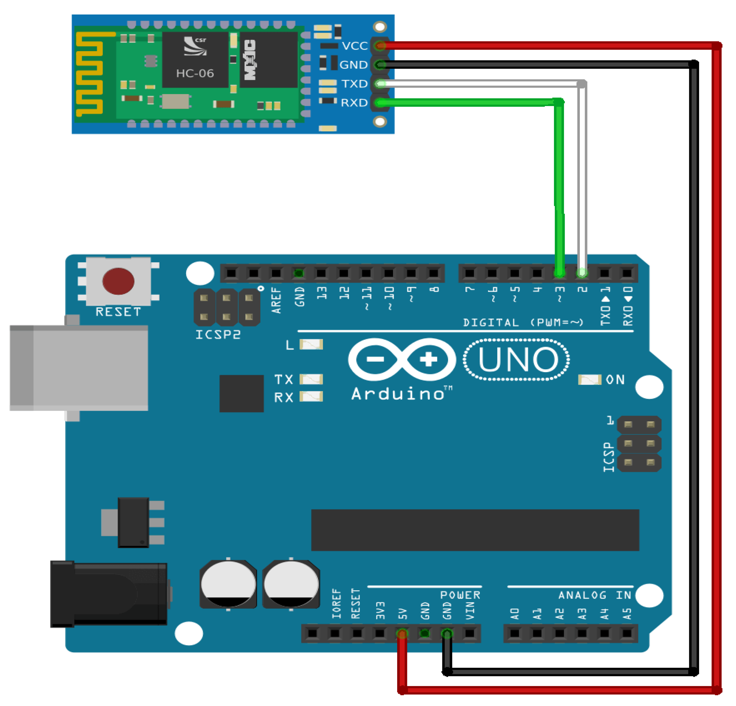
  • The interface circuit between the Android platform and the mobile phone using Bluetooth Module HC-06.
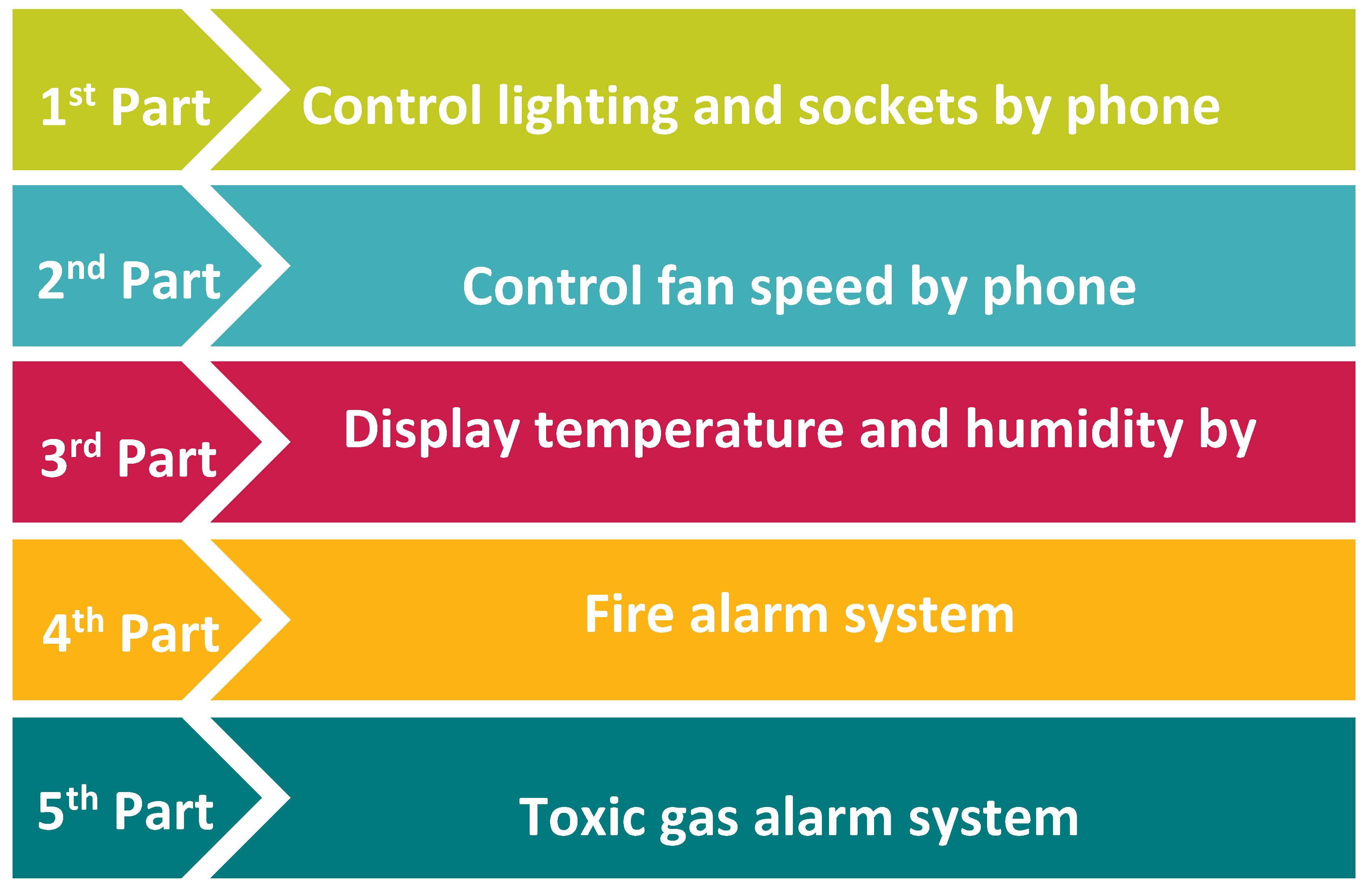
  • Five different applications for this smart home have been developed which control the lighting and electrical sockets, fan speed, the display for temperature and humidity settings, the fire alarm system, and the toxic gas alarm system.
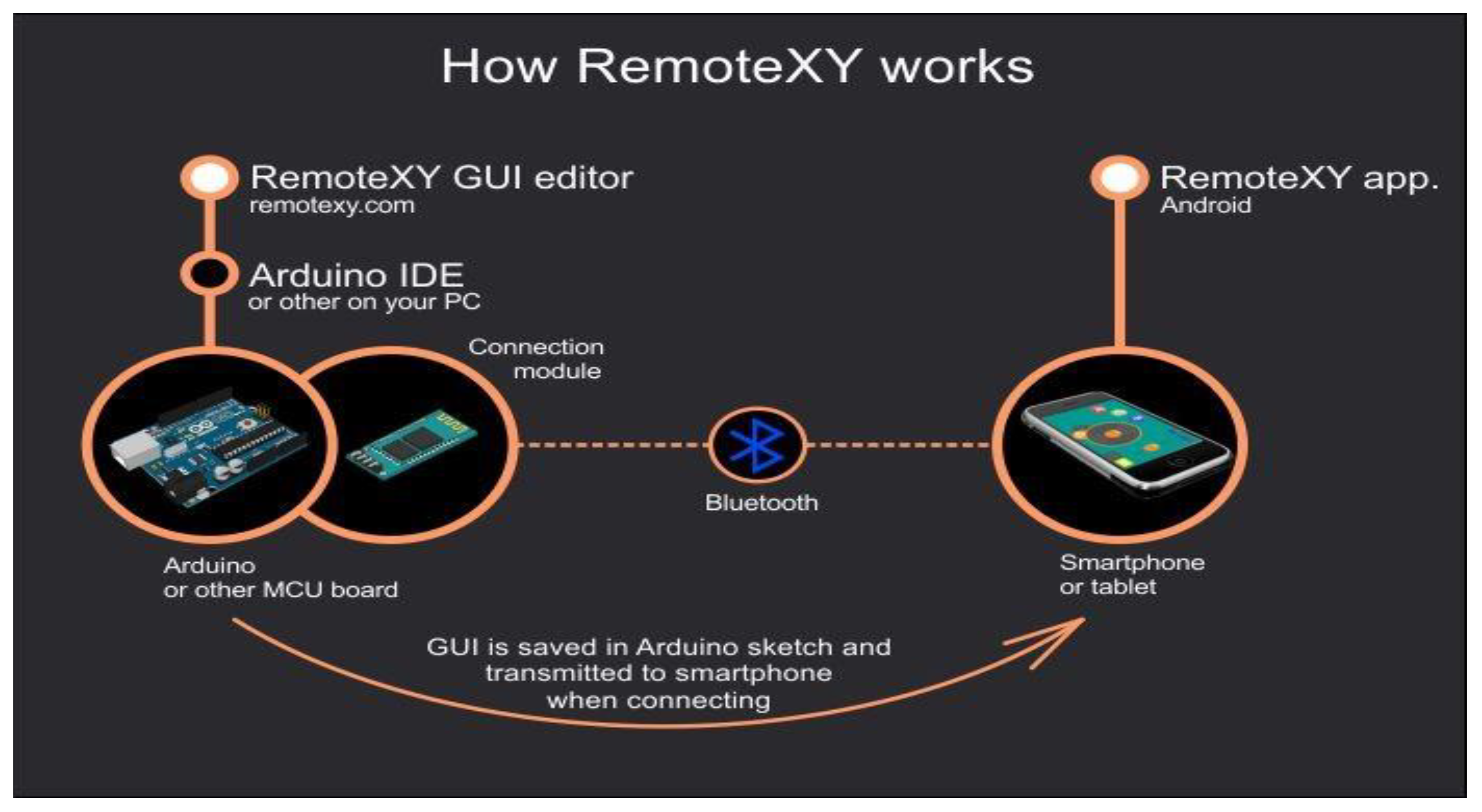
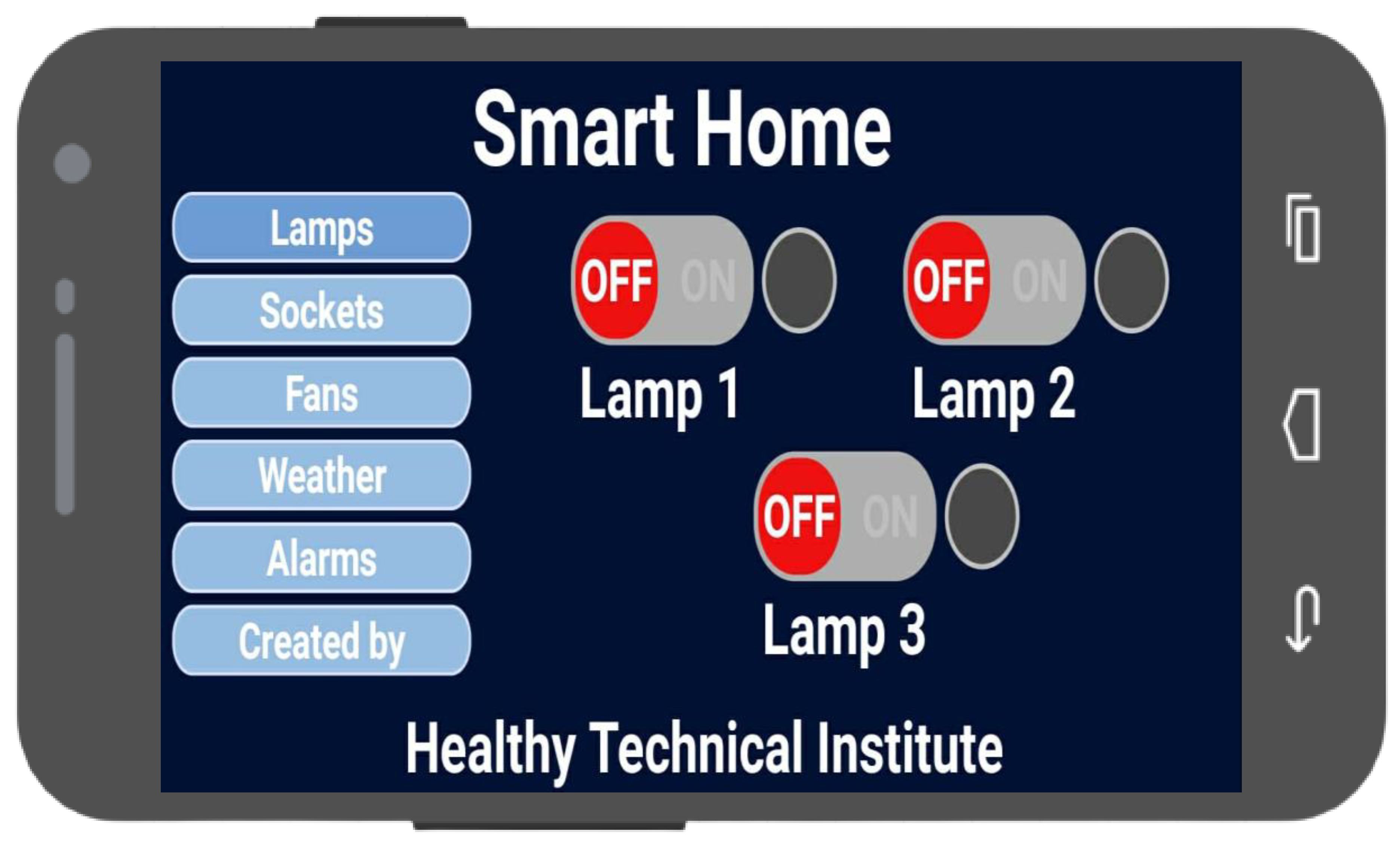
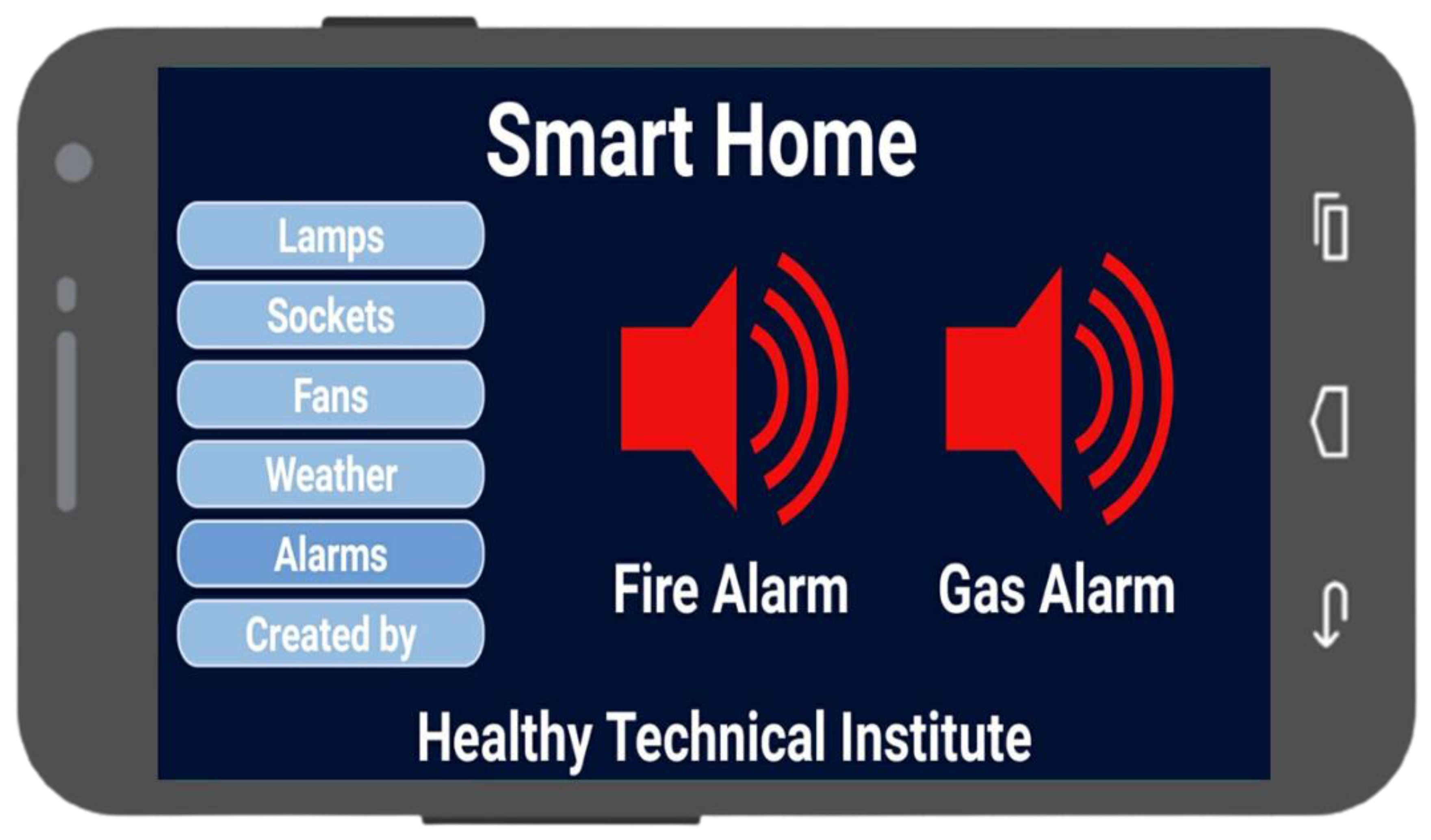
  • For all applications, a graphical user interface has been created based on the RemoteXY website.
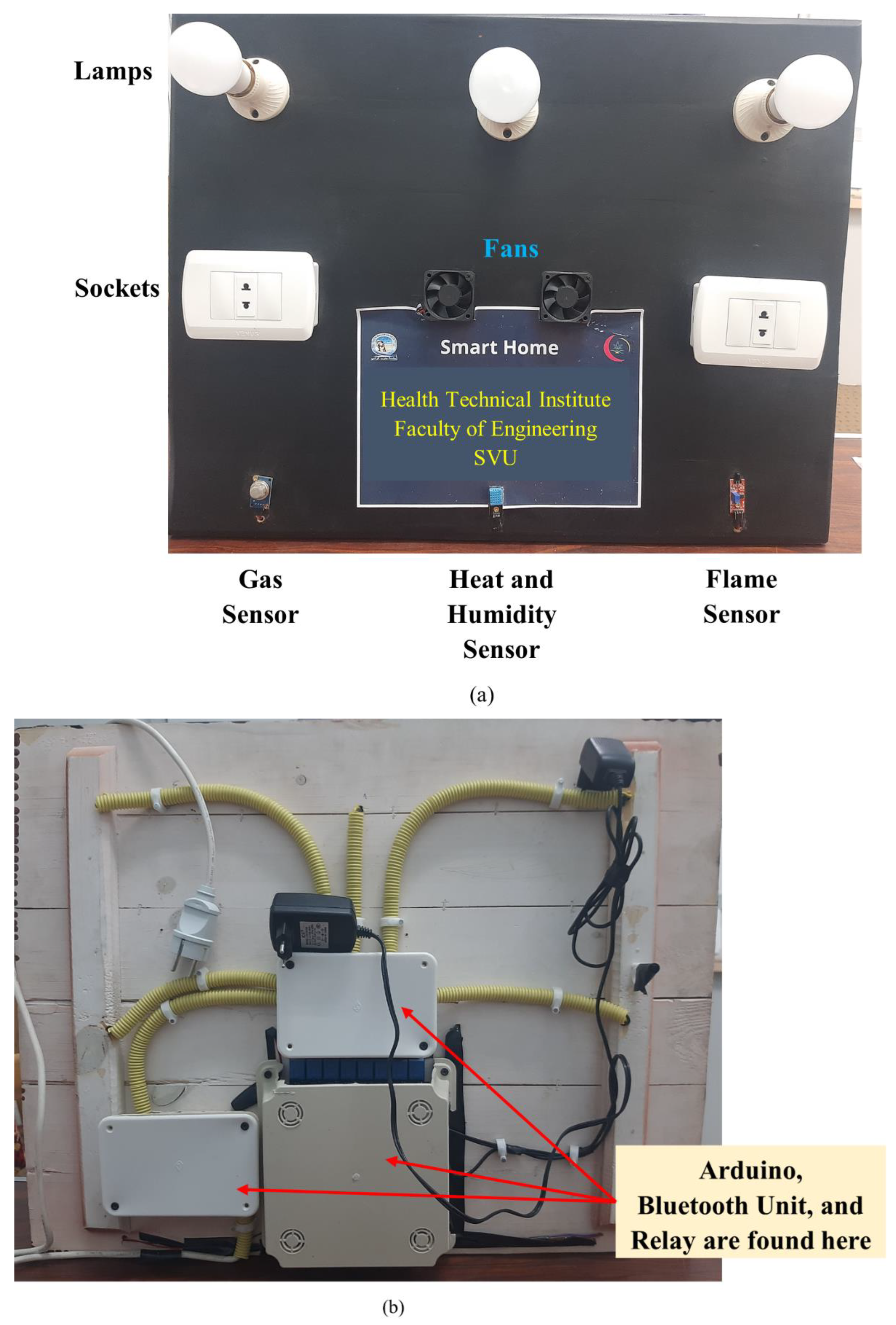
  • The components, the controls, and the wiring circuit are presented for each application and system. In addition, the system was investigated experimentally, and its effectiveness is proven through this research.
  • The system may relieve elderly populations, those with injuries, and people with disabilities from routine stresses and can provide these groups with increased independence.
  • The system efficiently manages energy consumption and helps with reducing the household’s carbon footprint.
The remainder of this paper is divided into the following sections: Section 2 presents the control unit and the interface between the Arduino and Android platforms. In Section 3 the systems developed for the smart home are explained in detail. The components, the graphical user interface, as well as the electronic and control circuits are presented for each application. In Section 4 some experiments are discussed for the smart home applications. Section 5 summarizes the main important points in this paper and provides some direction for future research.

2. Control Unit and Bluetooth Network

The Arduino UNO R3 and Bluetooth module used in this research are presented below. The Arduino UNO R3 [22,23,24] is extensively used in building projects because of its ease of use and programming. The one used here is a type ATmega328 which provides ports for directly connecting the electronic components, such as sensors, through 14 (entrance or exit) of the digital types of input/output. These 14 digital pins can work as inputs or exits and are used to insert and eject fixed digital signals 0 or 5. Each port can provide a current pull of up to 40 mA. Six of the ports can be used to obtain PWM (Pulse-Width modulation). In addition, the circuit contains a crystal oscillator at a 16 MHz frequency, a USB inlet for communication with the computer, and a separate inlet for energy. The power inputs/outputs are defined as follows: (1) the VIN or DC power jack is an outlet in which the Arduino can be run through an external power source such as a battery, (2) the 5V port can be used for sensors or other circuits, (3) the 3.3V port in which the maximum current value that can be utilized is 50 mAh, and (4) the GND port which is used to connect the ground line. Bluetooth Module HC-06 [25] is used to connect the Arduino Uno with the Android mobile phone. This module is one of the commonly used units with Arduino and it comprises four pins as follows: (1) the VCC pin, which is connected with the Arduino’s 5V output; (2) the GND pin, which is connected to the Arduino’s ground; (3) the TX pin, which is used to send the order from the phone to the Arduino and is connected to the Arduino’s RX; and (4) the RX pin, which is used to drop the order from the phone to the Arduino and is connected to the Arduino’s TX. These connections are shown in Figure 1.
RemoteXY [26] is a reliable website on the Internet that helps the programmer create a graphical user interface easily and free of charge. Therefore, this resource was chosen to create the GUI for the smart home applications. Figure 2 shows how RemoteXY works.

3. Smart Home Applications and Their Control Circuits

This section presents the developed five applications of the smart home. These applications are shown in Figure 3. This work was carried out through cooperation between the Health Technical Institute and the Faculty of Engineering at South Valley University, Qena, Egypt. The definitions, the components, and the control circuits for each application and system are discussed in detail in the following subsections.

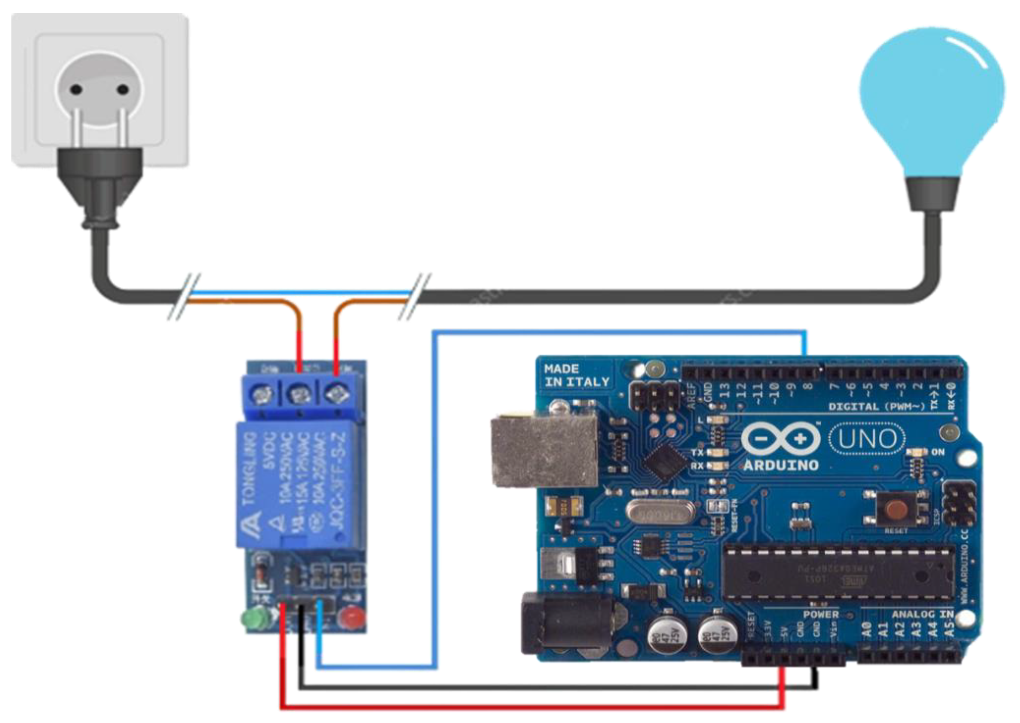
3.1. Lighting and Sockets Control

The aim of this system is to control the operation of lighting and electrical sockets in the home using an Android phone. In this case, three lamps and two sockets are used. Using the RemoteXY program, the GUI in the phone is arranged as presented in Figure 4. The main components of this system are presented in Table 2.
The control circuit is constructed by connecting the first end of the relay to the positive voltage, the second end of the relay to the ground of the circuit, and the third end of the relay to the output no. 8 of the Arduino. The lamp is connected in series with the relay. This circuit is illustrated in Figure 5. The implemented code is divided into two parts: the first part defines the functions of the keys within the RemoteXY software interface, in addition to the name and number of the pin switches that the user operates, while the second part is about defining pin states and integrating them with RemoteXY’s software interface. This code is presented in Appendix A.

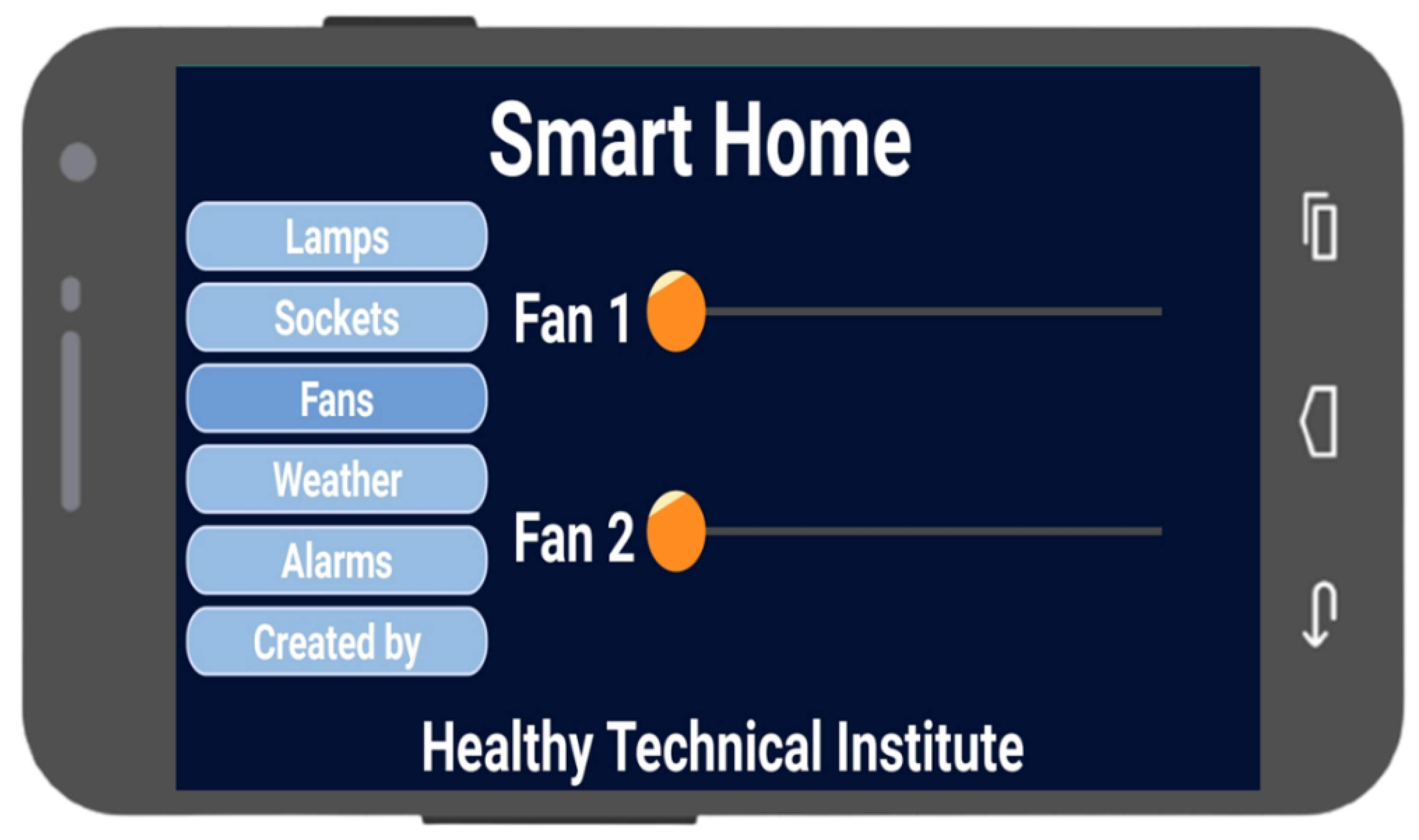
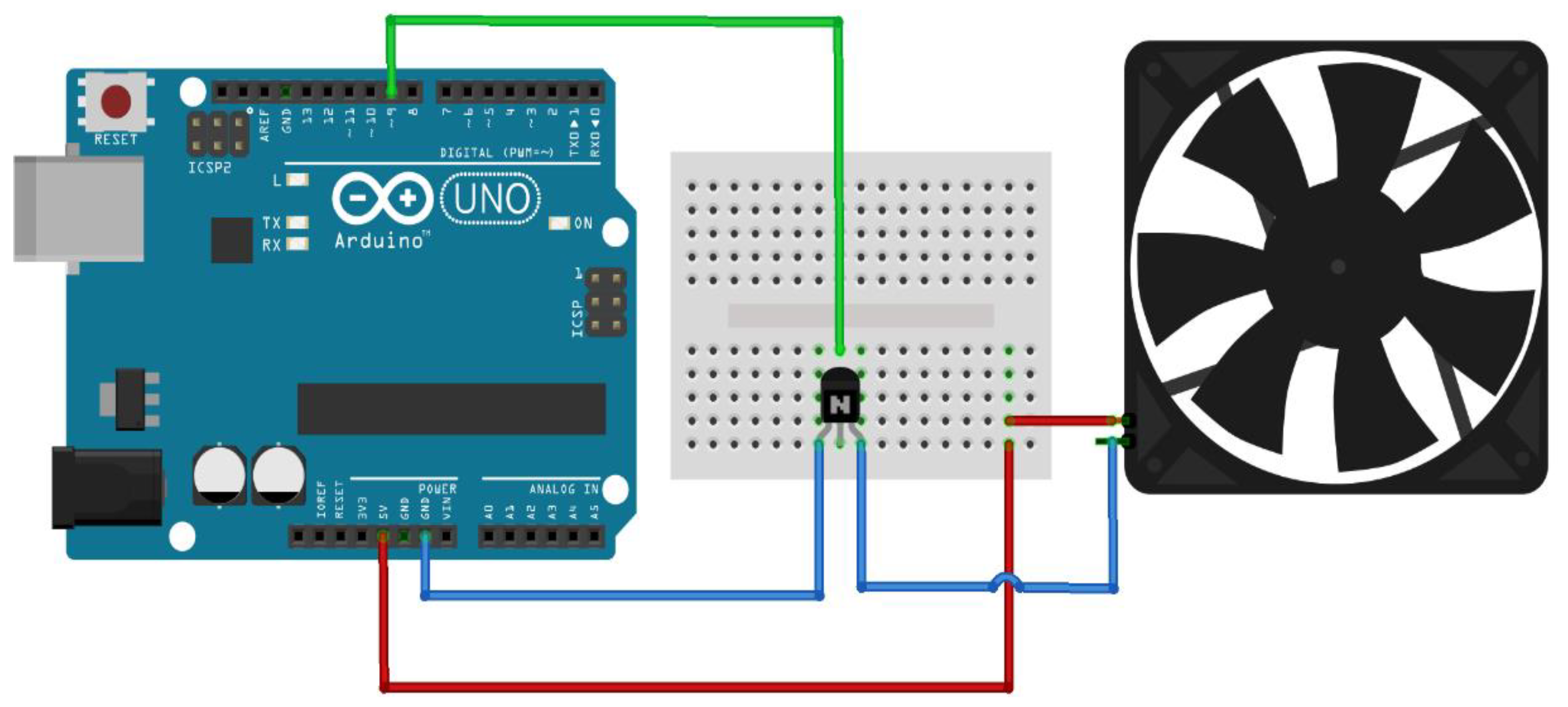
3.2. Fan Speed Control

The aim of this system is to control fan speed from the Android phone. In this case two fans are used. Using the RemoteXY program, the graphical user interface on the phone is arranged as shown in Figure 6. The main components of this system are presented in Table 3.
The control circuit for this system is constructed by connecting the output no. 9 of the Arduino to the base of the transistor. The first end of the fan is connected to the positive voltage, and the second end of the fan is connected to the collector of the transistor. The emitter of the transistor is connected to the ground of the circuit. This circuit is presented in Figure 7. The implemented code is also divided into two parts: the first part provides the definitions for the sliders within the RemoteXY software interface, in addition to the name and number of the pin switches that the user operates, while the second part is about defining states within the sliders and integrating them with RemoteXY’s software interface. This code is presented in Appendix B.

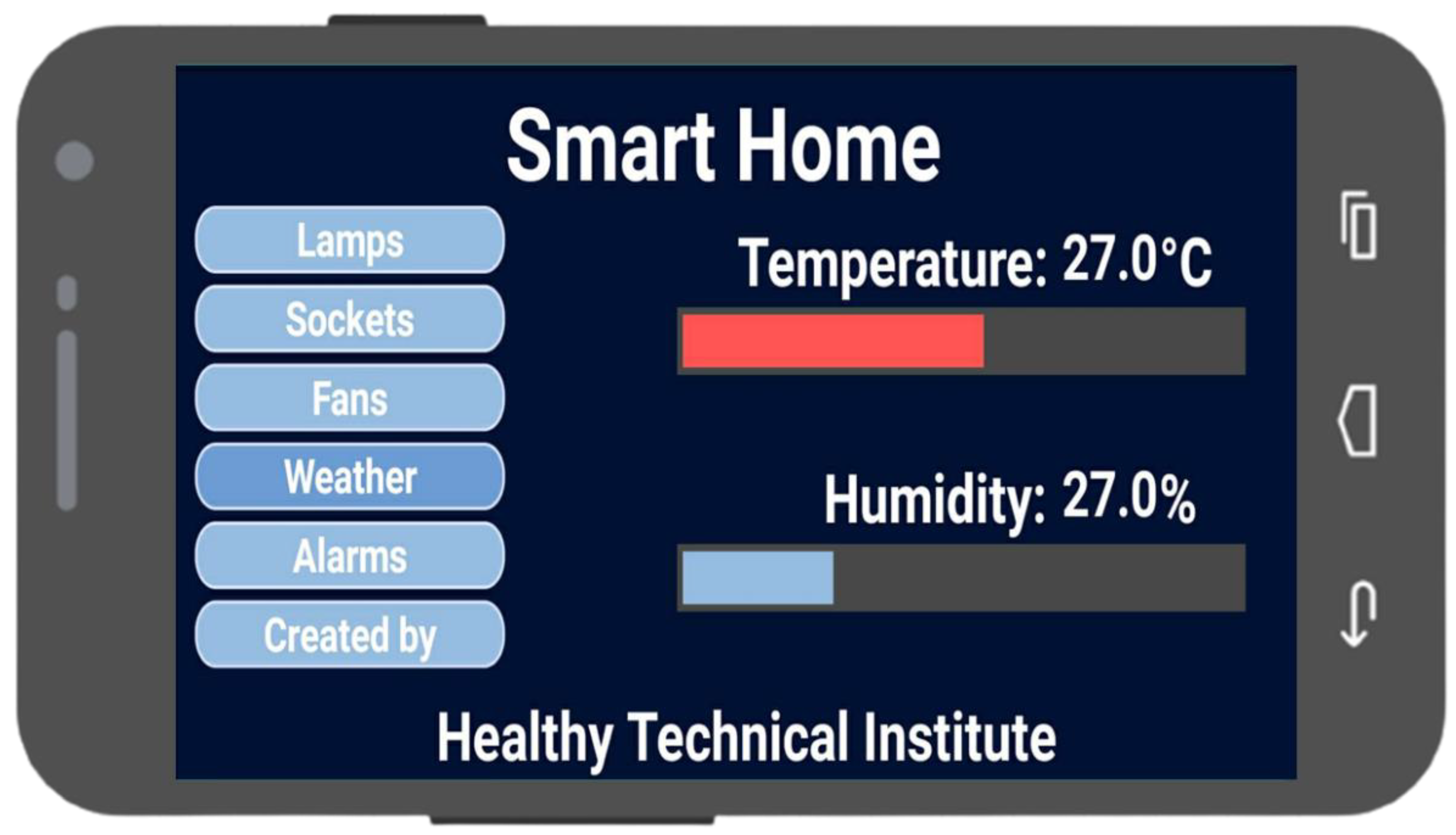
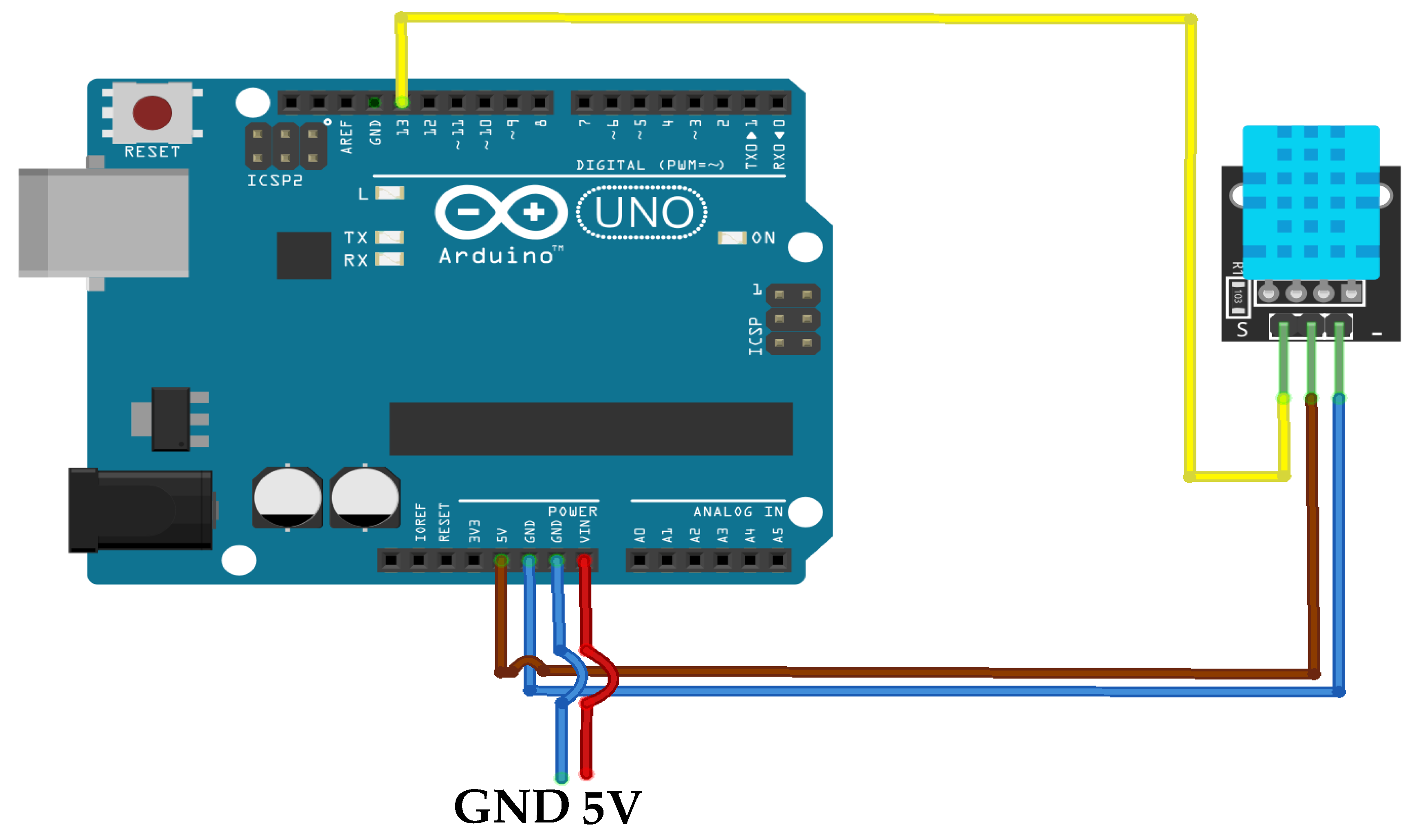
3.3. Temperature and Humidity Measurement

This system measures the temperature and humidity and displays it on the Android phone. Using the RemoteXY program, the GUI on the phone is arranged as shown in Figure 8. The main components of this system are presented in Table 4.
The control circuit of this system is constructed by connecting the sensor VCC terminal to the 5 V output of the Arduino; the sensor GND to the Arduino GND; and the sensor’s OUT to port no. 13 on the Arduino from which it receives the signal. This circuit is presented in Figure 9. The implemented code is divided also into two parts: the first part defines the text and level within the program interface for the RemoteXY program and defines a library for temperature and humidity sensors, whereas the second part programs the texts and levels to display temperature and humidity data. This code is presented in Appendix C.

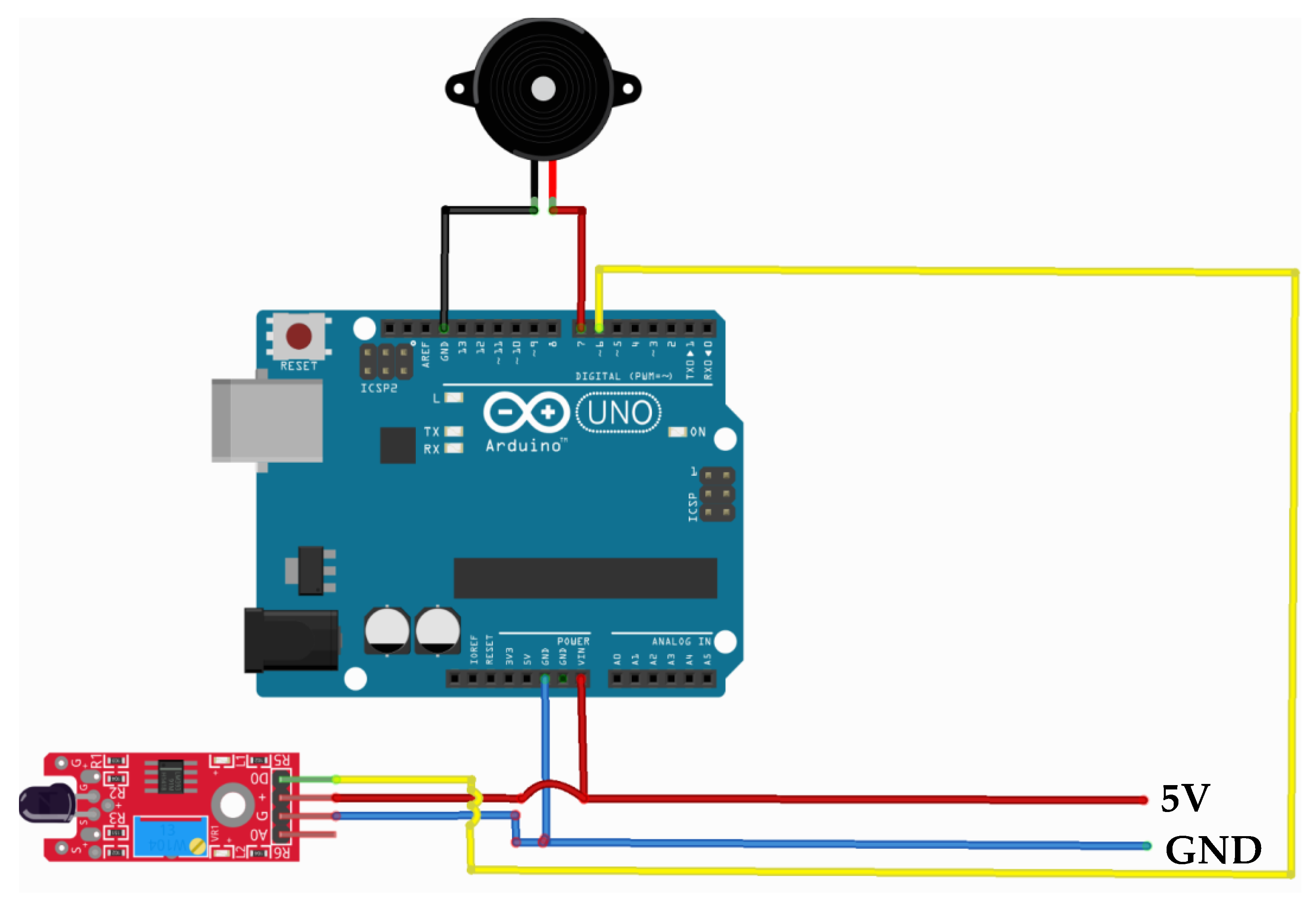
3.4. Fire Alarm System

The purpose of this system is to turn on an alarm when there is a fire detected inside the house. The implemented graphical user interface on the Android phone is presented in Figure 10. The main required components for this system are illustrated in Table 5.
The control circuit of this system is constructed as follows. The Arduino port is connected to a power source; the VCC terminal of the sensor is connected to the 5-volt terminal of the power source; the GND end of the sensor is connected to the ground; and the D-OUT for the sensor is connected to the port no. 6 of the Arduino unit. This circuit is shown in Figure 11. The executed code for this part is presented in Appendix D.

3.5. Toxic Gas Leak Warning System

The main objective of this system is to turn on an alarm in the event that toxic gases (CH4, CO, or H2S) are leaking and their air-concentration levels rise inside the house. The graphical user interface on the android phone is the same as the one presented in Figure 10. The main components for this system are presented in Table 6.
The control circuit of this system is constructed as follows. The Arduino port is connected to a power source; the VCC terminal of the sensor is connected to the 5-volt terminal of the power source; the GND end of the sensor is connected to the ground; and the D-OUT for the sensor is connected to the port no. 6 of the Arduino unit. This circuit is presented in Figure 12. The executed code for this system is presented in Appendix E.

4. Experiments

All the components controlled by the five applications are rigidly connected to a wooden board/panel to simulate the smart home, as shown in Figure 13.
All the developed smart home applications and systems are investigated using the created GUI on the mobile phone. The user turns the ON and OFF switches for the three lamps easily using the mobile phone interface. The two electrical sockets are tested by connecting them to two mobile chargers. When the user switches the socket to ON, the mobile device starts charging and when the person turns it to OFF, the mobile charging is stopped. The user can increase and decrease the speed of the two fans easily using the graphical user interface. The temperature and the humidity data for the surrounding air are displayed correctly in the graphical user interface. When there is a flame or gas leakage detected, the sensors activate their respective alarm system. In conclusion, the developed smart home applications work efficiently and correctly. A demo video for these experiments is available at the following link: https://www.youtube.com/watch?v=LlYoM6kFP_A&t=19s (accessed on 12 June 2022).
Supplementary materials are attached to this paper and available for any interested researcher which contain the implemented code, the used Arduino software, the used alarm voices, and the RemoteXY.

5. Conclusions and Future Work

For this paper, five applications for the smart home were successfully developed and controlled via an Android mobile phone and an Arduino platform. The applications control the lighting and electrical sockets, the fan speed control, the temperature and humidity display, the fire alarm system, and the toxic gas alarm system in a simulated smart home. The required components for these systems were procured and then the controls and wiring circuits were implemented. A GUI designed for use on a mobile phone was created using the RemoteXY software. The developed systems were tested and found to be working efficiency. Finally, this concept is very cost-effective which indicates an encouraging probability of mass adoption and commercialization of similar systems. Furthermore, these systems are easily utilized by beneficial for people with disabilities, those suffering from injury, and elderly populations. In future research, Arduino units could be connected to Android mobile phones via Wi-Fi. In addition, different controllers could be used and investigated such as PLCs. The focus of this paper could also be expanded to the level of smart city applications.

Supplementary Materials

The following supporting information can be downloaded at: https://www.mdpi.com/article/10.3390/automation3040029/s1, the implemented code, the used Arduino software, the used alarm voices, and the RemoteXY. Code S1: The implemented code for smart home applications in Arduino unit.

Author Contributions

Conceptualization, A.-N.S.; Data curation, A.-N.S., M.H., M.S. and M.M.; Investigation, A.-N.S. and A.E.; Methodology, A.-N.S., M.H., M.S. and M.M.; Project administration, A.E.; Software, A.-N.S., M.H., M.S. and M.M.; Supervision, A.E.; Visualization, A.-N.S.; Writing—original draft, A.-N.S.; Writing—review & editing, A.-N.S. and A.E. All authors have read and agreed to the published version of the manuscript.

Funding

This research received no external funding.

Institutional Review Board Statement

Not applicable.

Informed Consent Statement

Not applicable.

Data Availability Statement

Not applicable.

Conflicts of Interest

The authors declare no conflict of interest.

Appendix A. The Executed Code Used to Control Lighting and Sockets

Figure A1. The first part of the executed code used to control lighting and sockets.
Automation 03 00029 g0a1
Figure A2. The second part of the executed code used to control lighting and sockets.
Automation 03 00029 g0a2

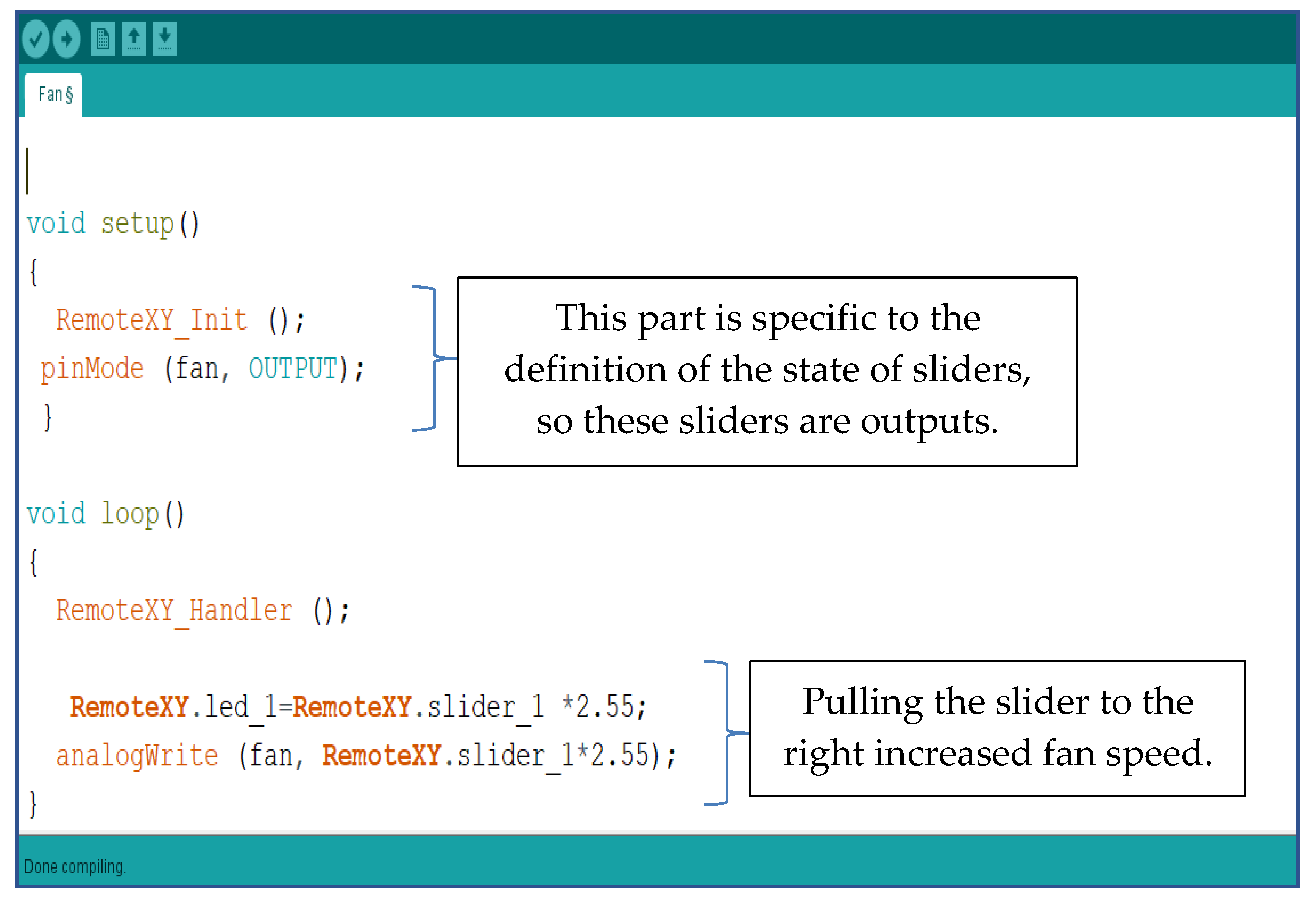
Appendix B. The Executed Code Used to Control Fan Speed

Figure A3. The first part of the executed code used to control the fan speed.
Automation 03 00029 g0a3
Figure A4. The second part of the executed code used to control the fan speed.
Automation 03 00029 g0a4

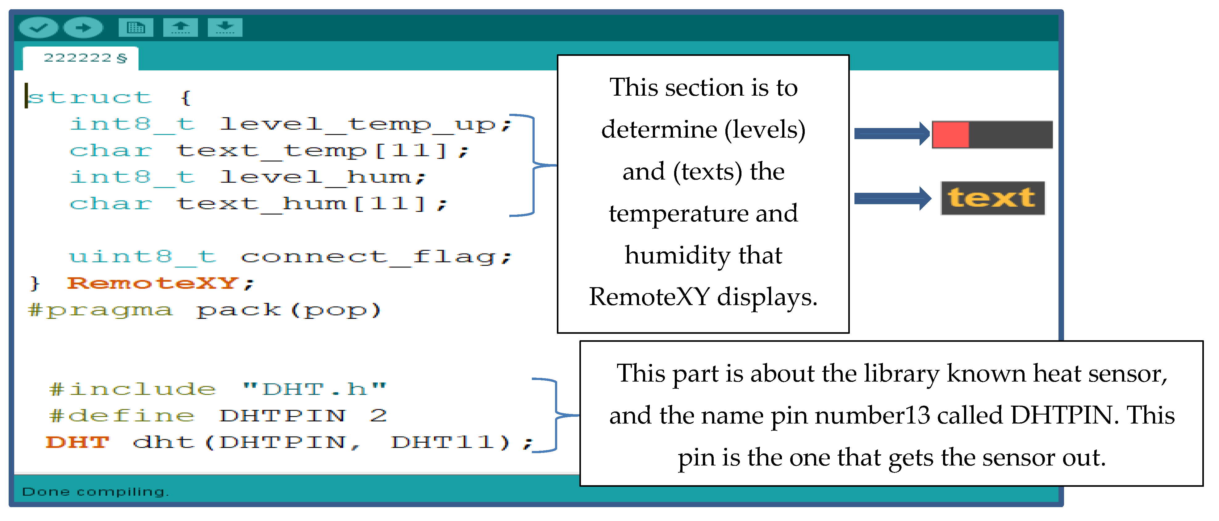
Appendix C. The Executed Code for Programming the Heat and Humidity Sensor

Figure A5. The first part of the executed code used to program the heat and humidity sensor.
Automation 03 00029 g0a5
Figure A6. The second part of the executed code used to program the heat and humidity sensor.
Automation 03 00029 g0a6

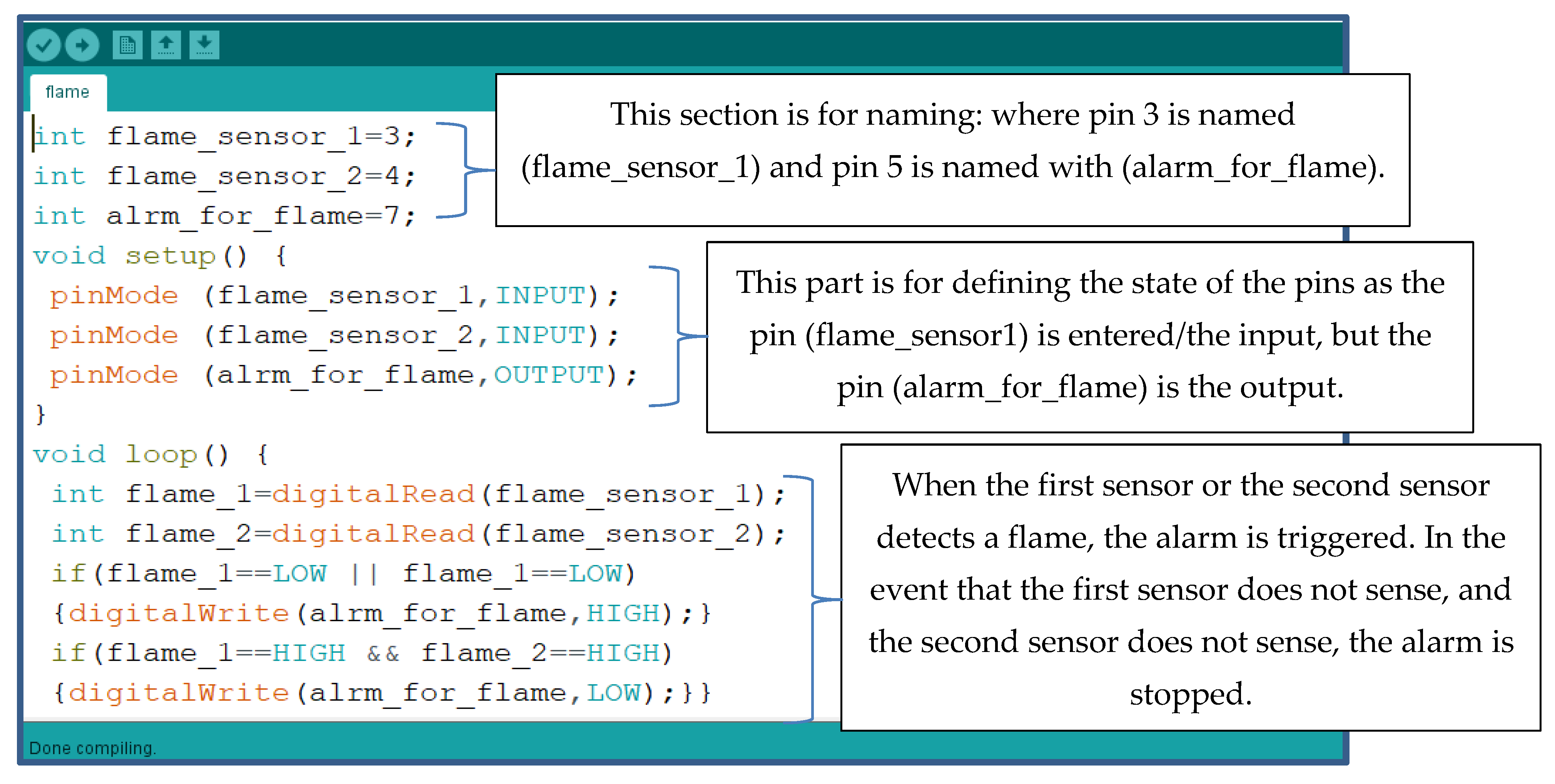
Appendix D. The Executed Code for the Fire Alarm System

Figure A7. The implemented code for the fire alarm system.
Automation 03 00029 g0a7

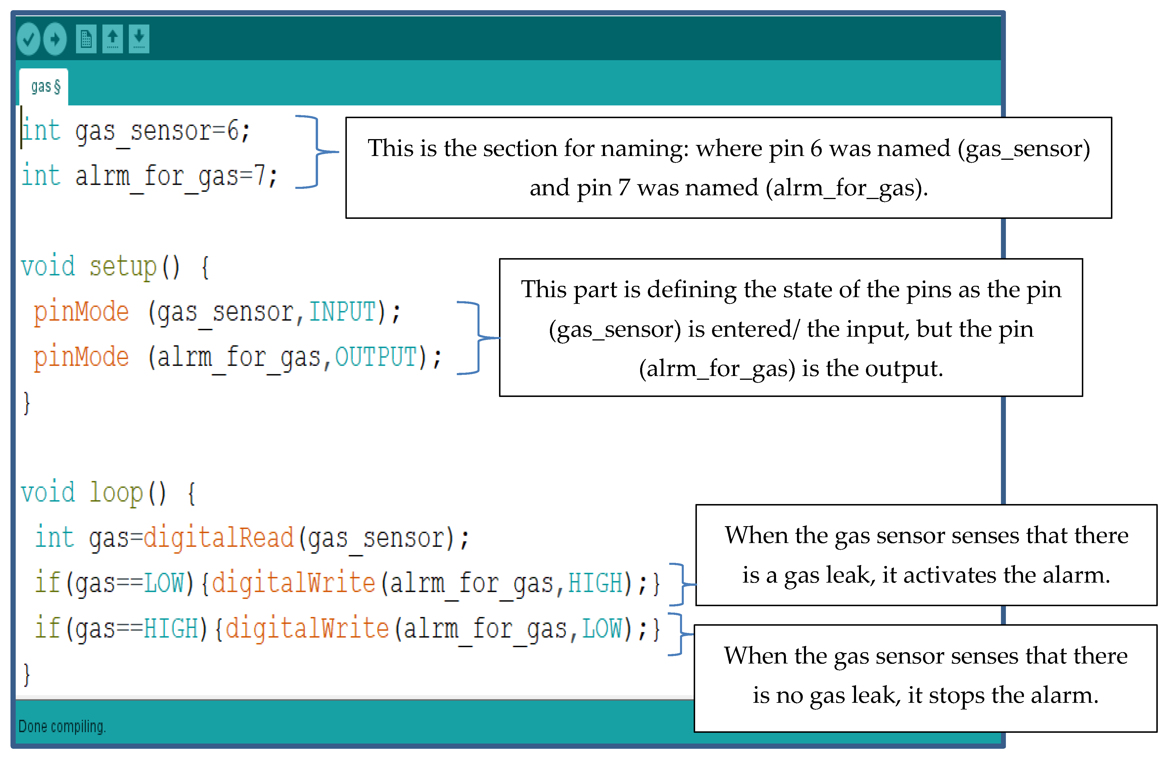
Appendix E. The Executed Code for the Toxic Gas Leak System

Figure A8. The implemented code for the toxic gas leak system.
Automation 03 00029 g0a8

References

  1. Alaa, M.; Zaidan, A.A.; Zaidan, B.B.; Talal, M.; Kiah, M.L.M. A review of smart home applications based on Internet of Things. J. Netw. Comput. Appl. 2017, 97, 48–65. [Google Scholar] [CrossRef]
  2. Rosslin, J.R.; Tai-Hoon, K. Applications, Systems and Methods in Smart Home Technology: A Review. Int. J. Adv. Sci. Technol. 2010, 15, 37–48. [Google Scholar]
  3. Suresh, S.; Sruthi, P.V. A review on smart home technology. In Proceedings of the 2015 Online International Conference on Green Engineering and Technologies (IC-GET), Coimbatore, India, 27 November 2015; pp. 1–3. [Google Scholar]
  4. Geraldo Filho, P.R.; Villas, L.A.; Gonçalves, V.P.; Pessin, G.; Loureiro, A.A.; Ueyama, J. Energy-efficient smart home systems: Infrastructure and decision-making process. Internet Things 2019, 5, 153–167. [Google Scholar] [CrossRef]
  5. Sarhan, Q.I. Systematic Survey on Smart Home Safety and Security Systems Using the Arduino Platform. IEEE Access 2020, 8, 128362–128384. [Google Scholar] [CrossRef]
  6. Sasikala, S.; Chitranjan, O.R.; Muthulakshmi, K. Implementation of home automation safety control using programmable logic controller. Middle East J. Sci. Res. 2014, 20, 492–501. [Google Scholar]
  7. Yilmaz, C. Implementation of programmable logic controller-based home automation. J. Appl. Sci. 2010, 10, 1449–1454. [Google Scholar] [CrossRef] [Green Version]
  8. Barz, C.; I Deaconu, S.; Latinovic, T.; Berdie, A.; Pop-Vadean, A.; Horgos, M. PLCs used in smart home control. IOP Conf. Ser. Mater. Sci. Eng. 2016, 106, 1–6. [Google Scholar] [CrossRef] [Green Version]
  9. Hasirci, Z.; Cavdar, I.H.; Suljanović, N.; Mujčić, A. An Application of the Broadband PLC for Smart Homes in Turkey. In Proceedings of the 2013 36th International Conference on Telecommunications and Signal Processing (TSP), Rome, Italy, 2–4 July 2013; pp. 1–5. [Google Scholar]
  10. Cheng, Y.H.; Chao, P.J.; Liang, H.Y.; Kuo, C.N. Smart home environment management using programmable logic controller. Eng. Lett. 2020, 28, 1174–1181. [Google Scholar]
  11. Bingol, O.; Tasdelen, K.; Keskin, Z.; Kocaturk, Y.E. Web-based Smart Home Automation: PLC- controlled Implementation. Acta Polytech. Hung. 2014, 11, 51–63. [Google Scholar]
  12. Sarangapani, E.; Narmadhai, N.; Santhosh, N. Industry 4.0 technologies incorporated with Delta PLC based Smart Home Automation for Rural Development. IOP Conf. Ser. Mater. Sci. Eng. 2021, 1084, 012112. [Google Scholar] [CrossRef]
  13. Naing, M.; Hlaing, N.N.S. Arduino Based Smart Home Automation System. Int. J. Trend Sci. Res. Dev. 2019, 3, 276–280. [Google Scholar] [CrossRef]
  14. Majhi, A.K.; Dash, S.; Barik, C.K. Arduino based smart home automation system. Accent. Trans. Inf. Secur. 2021, 6, 7–12. [Google Scholar]
  15. Raza, A.; Baloch, M.H.; Hussain, S.; Malik, M.Z.; Ali, I.; Ali, A.; Ali, A. A Home Automation through Android Mobile App by Using Arduino UNO. In Proceedings of the 2020 23rd IEEE International Multi-Topic Conference, INMIC 2020, Bahawalpur, Pakistan, 5–7 November 2020; pp. 1–6. [Google Scholar]
  16. Chandramohan, J.; Satheeshkumar, K.; Gopinath, P.A.; Ajithkumar, N.; Ranjithkumar, S. Implementation of Smart Home Automation and Security System Using Arduino and Wi-Fi through Android Application. Int. J. Eng. Res. Technol. 2017, 5, 13–17. [Google Scholar]
  17. Budiyanto, S.; Silalahi, L.M.; Silaban, F.A.; Salamah, K.S.; Rahayu, F.; Wahyuddin, M.I.; Andryana, S. Design of control and monitoring tools for electricity use loads, and home security systems with internet of things system based on Arduino Mega 2560. IOP Conf. Ser. Mater. Sci. Eng. 2020, 909, 012020. [Google Scholar] [CrossRef]
  18. Singh, S.; Patra, A.; Shrivastav, T. Home Automation using Arduino With Bluetooth Module. Int. J. Innov. Res. Electr. Electron. Instrum. Control Eng. 2021, 9, 318–320. [Google Scholar]
  19. Balasingam, S.; Zapiee, M.K.; Mohana, D. Smart Home Automation System Using IOT. Int. J. Recent Technol. Appl. Sci. 2022, 4, 44–53. [Google Scholar] [CrossRef]
  20. Islam, F.; Hasan, I.; Akter, M.; Uddin, M.S. Implementation and Analysis of an IoT-Based Home Automation Framework. J. Comput. Commun. 2021, 9, 143–157. [Google Scholar] [CrossRef]
  21. Yar, H.; Imran, A.S.; Khan, Z.A.; Sajjad, M.; Kastrati, Z. Towards Smart Home Automation Using IoT-Enabled Edge-Computing Paradigm. Sensors 2021, 21, 4932. [Google Scholar] [CrossRef] [PubMed]
  22. Arduino Uno. Available online: https://datasheet.octopart.com/A000066-Arduino-datasheet-38879526.pdf (accessed on 7 October 2022).
  23. Arduino For Beginners. Available online: https://www.makerspaces.com/wp-content/uploads/2017/02/Arduino-For-Beginners-REV2.pdf (accessed on 7 October 2022).
  24. Sharkawy, A.-N.; Abdel-Jaber, G.T. Design and Implementation of a Prototype of Elevator Control System: Experimental Work. SVU Int. J. Eng. Sci. Appl. 2022, 3, 80–86. [Google Scholar] [CrossRef]
  25. HC-06 Bluetooth Module. 2018. Available online: https://components101.com/wireless/hc-06-bluetooth-module-pinout-datasheet (accessed on 3 November 2018).
  26. RemoteXY. Available online: https://remotexy.com/en/ (accessed on 7 October 2022).
Figure 1. The connections between the Bluetooth Module HC-06 and the Arduino Uno.
Automation 03 00029 g001
Figure 2. The work of RemoteXY in creating the graphical user interface.
Automation 03 00029 g002
Figure 3. The five developed smart home applications in this paper.
Automation 03 00029 g003
Figure 4. The graphical user interface used to control the operation of lighting and sockets.
Automation 03 00029 g004
Figure 5. The control circuit for the operation of lighting and sockets in the smart home.
Automation 03 00029 g005
Figure 6. The graphical user interface used to control the speed of the fans.
Automation 03 00029 g006
Figure 7. The control circuit for the fan speed in the smart home.
Automation 03 00029 g007
Figure 8. The graphical user interface used to display the temperature and humidity of the smart home on the phone.
Automation 03 00029 g008
Figure 9. The control circuit for displaying the temperature and humidity in the smart home.
Automation 03 00029 g009
Figure 10. The graphical user interface on the phone for controlling the fire alarm system in the smart home.
Automation 03 00029 g010
Figure 11. The control circuit for the fire alarm system in the smart home.
Automation 03 00029 g011
Figure 12. The control circuit for the toxic gas warning system in the smart home.
Automation 03 00029 g012
Figure 13. The simulation of the smart home: (a) All of the components (lamps, sockets, fans, and sensors) controlled by the five developed applications are arranged on the front side of the panel. (b) The connections, wires, Arduino unit, Bluetooth unit, and relay are configured on the back side of the panel.
Automation 03 00029 g013
Table 1. The comparison between some developed smart home applications stated in literature.
ResearchersYearNumber of Developed Smart Home ApplicationsControlled ApplicationsControllerInterfaceGaps and Disadvantages
Sasikala et al. [6]20141- ON and OFF statusPLCHMI- Few developed applications [1 or 3 only].
- Local use only and remote sensing technology was not considered.
- The required cost is not clear.
Yilmaz, [7]20103- Gas sensing
- Voltage control of power socket
- Circuits of valve control
PLCNot stated
Barz et al. [8]20163- Lighting
- Room temperature
- Irrigation systems
PLCHMI Weintek eMT3070a touchscreen
Naing and Hlaing, [13]20193- Light
- Room temperature
- Alarms and security system
Arduino NanoSMS
Majhi et al. [14]20213- Electric bulb—Fans
- Alerts if there was a fire breakout
Arduino unitSMS using the GSM Module
Raza et al. [15]20201- Only the lightArduino unitBluetooth (HC-05) Module- Few developed applications [1 or 2 only].
- The required cost is not clear.
Chandramohan et al. [16]20172- Lamps
- Fans
Arduino unitWi-Fi
Table 2. The main components used to control the operation of lighting and sockets.
ComponentDefinitionTechnical Specifications
LampsThese are used in the normal lighting of the smart home- Operating voltage: 220V.
- Power: 10 Watt.
- Life span: 25,000 H.
Module RelayIt is used to amplify the signal from the Arduino unit so that it can operate the high voltage components- Operating voltage: 5V.
- Electric current: 10 A.
Table 3. The main components used to control the fan speed.
ComponentDefinitionTechnical Specifications
FansTwo fans are used to ventilate the rooms of the smart house.- Operating voltage: 5V.
- Electric current: 200 mA.
- Size: 5 cm × 5 cm.
TransistorIt is used to amplify the signal, and it consists of three terminals: base, emitter, and collector.- Type: 2N2222 (PNP)
- Operating voltage: 0.7 V.
- Collector current (DC): 800 mA.
- Total power dissipation: 500 mW.
Table 4. The main components used to control the humidity and temperature system.
ComponentDefinitionTechnical Specifications
Heat and Humidity Sensor (DHT11 Module)- This sensor gives a digital signal that is in line with temperature and humidity and these signals are easy to read by the Arduino unit.
- It consists of three pins as follows:
(1) the VCC, which is the positive voltage connected to 3.3 V and 5.5 V.
(2) the GND which is connected to the Arduino’s ground.
(3) the OUT which sends temperature and humidity data to the Arduino.
- Operating voltage from 3.3–5.5 volts.
- Digital reading and using a single exit.
- Temperature reading from 0 to 50 °C and relative humidity from 20–90%.
- Accuracy: ±5% for humidity and ±2°C.
- Standard measurement indicator: 1% for humidity and 1 °C for heat.
- Measurement changes factor over sensitive age: ±1% for humidity/year.
Table 5. The main components for the fire alarm system in the smart home.
ComponentDefinitionTechnical Specifications
Flame Sensor-It is used to detect fire or light sources of wavelength in the range of 760–1100 nm. This sensor is of a YG1006 type which is a light transistor.
-It can detect infrared radiation from the flame and detect fire in a range of 60 degrees Celsius.
- This sensor has four pins as follows:
(1) the VCC which is the voltage supply from 3.3 V to 5.5 V.
(2) the GND which should be grounded.
(3) the OUT-D which is responsible for the digital output of the signal.
(4) the OUT-A which is responsible for the analog output of the signal.
- The ability to output digital signals (high and low).
- The output capacity of an analogue signal (voltage signal) can be measured with more accuracy and is suitable in case there is a need for high accuracy.
- Operating voltage: 3.3–5 V.
- After detection: 20 cm (4.8 volts)–100 cm (1 volts).
- The detection angle is approximately 60 degrees.
Table 6. The main components for the toxic gas warning system in the smart home.
ComponentDefinitionTechnical Specifications
Gas Sensor (MQ2)- It is used in the MQ series sensor.
- It is a metal oxide sensor (MOS) and known as Chemiresistors because detection depends on changing the resistance of the sensor when the gas comes into contact with the substance.
- Using a simple voltage divider network, gas leakage can be detected.
- This sensor detects many types of toxic gases such as LPG, smoke, alcohol, propane, hydrogen, methane, and carbon monoxide.
- The sensor consists of four pins as follows:
(1) the VCC which is connected to a positive voltage of 5 V.
(2) the GND which should be grounded.
(3) the OUT-D which is responsible for outputting the digital signal.
(4) the OUT-A which is responsible for the analog output of the signal.
- Power consumption: mW > 800
- Sensor resistance: 5% ± 33 Ω
- Operating voltage: 5 V
- Focus range: 200–10,000 ppm
Publisher’s Note: MDPI stays neutral with regard to jurisdictional claims in published maps and institutional affiliations.

