Design and Analysis of Transformable Wheel with Pivoting-Head Mechanism

Abstract
:1. Introduction
2. Structure and Working Principle of Transformable Wheel
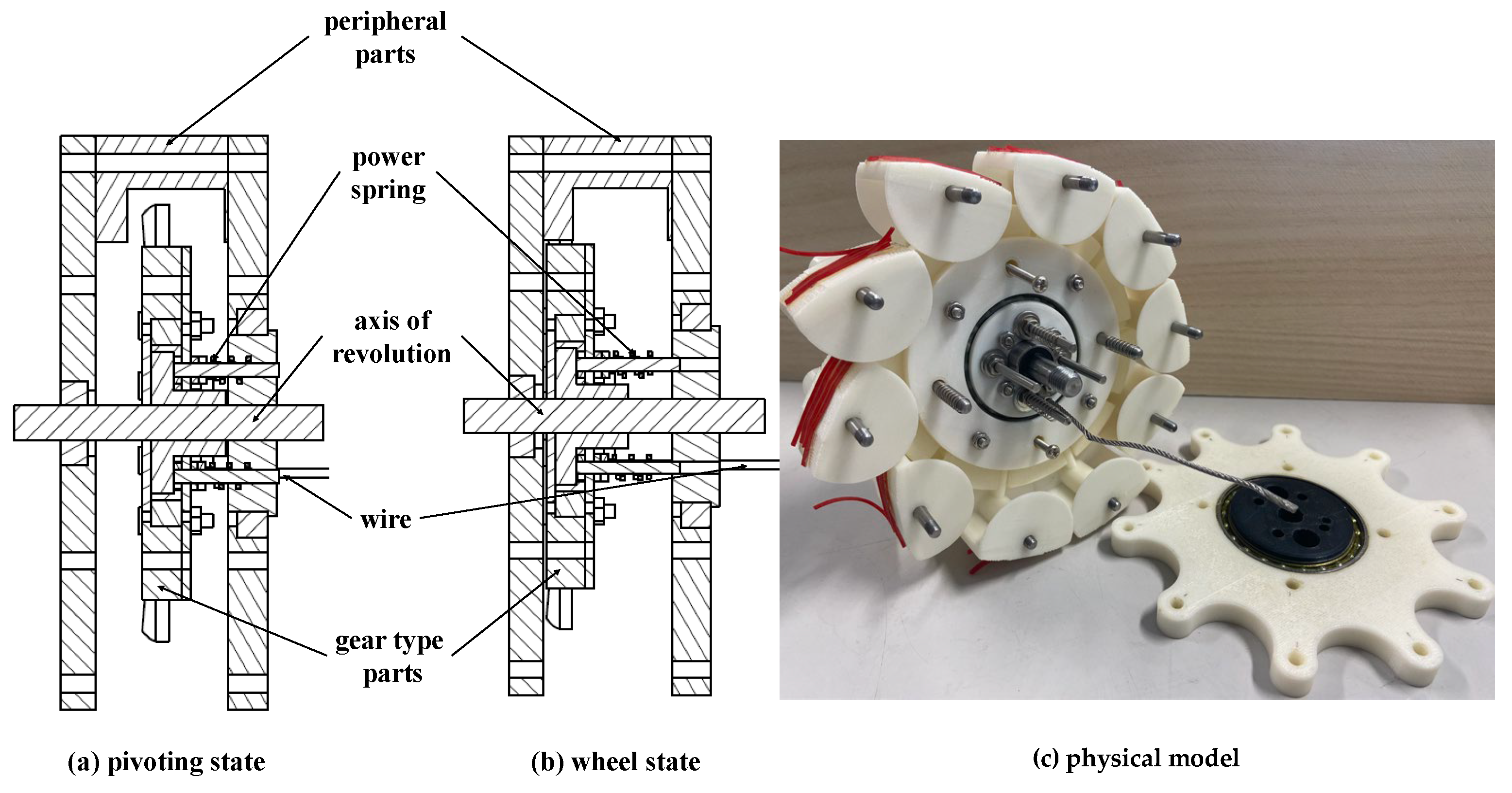
2.1. Structure
2.2. Working Principle
3. Obstacle Surmounting Performance Analysis
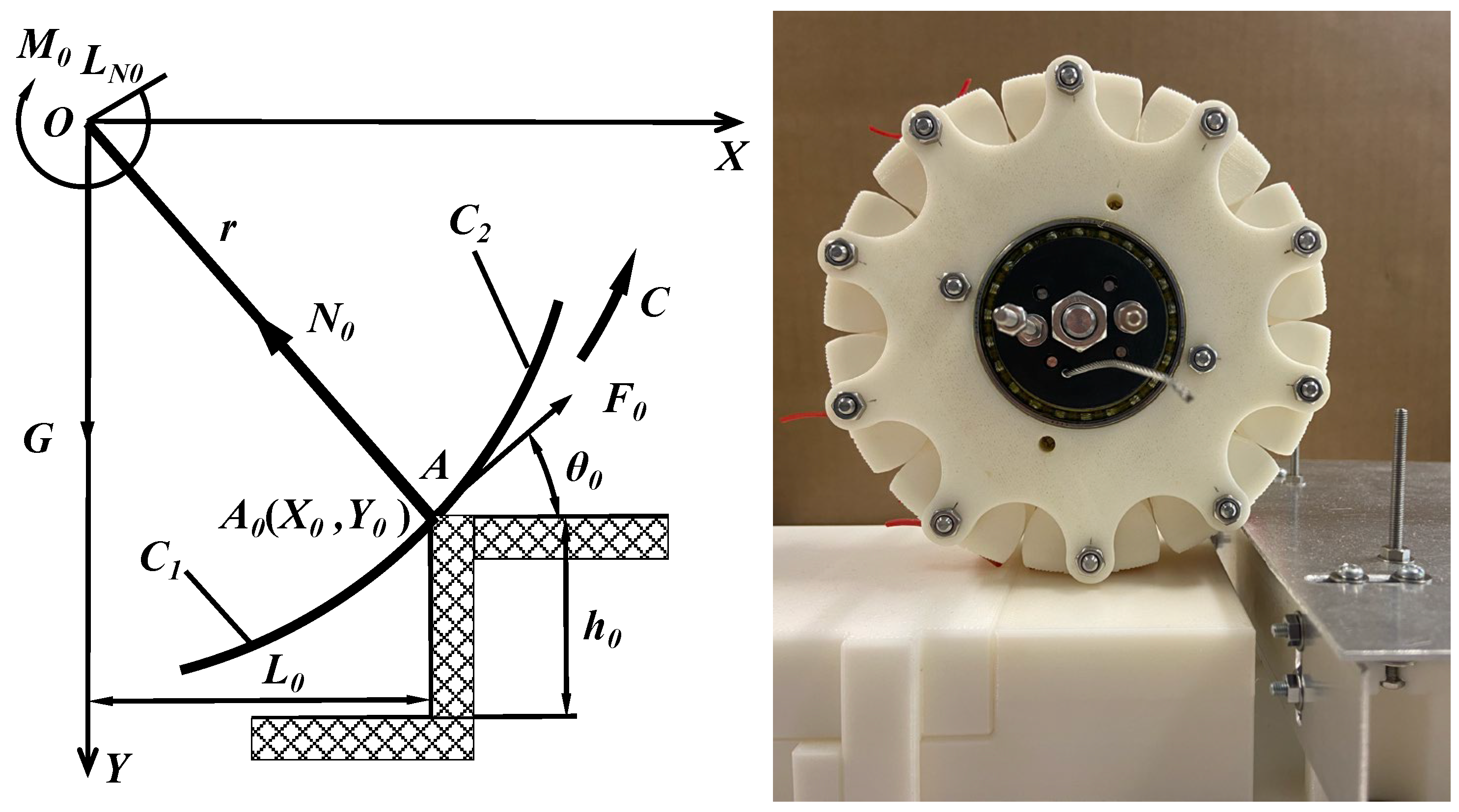
3.1. Analysis of the Round Wheel Obstacle Surmounting Performance
3.2. Theoretical Analysis of the Transformable Wheel Obstacle Surmounting
3.2.1. Mechanical Analysis of Contact Obstacle Surmounting in Section C1
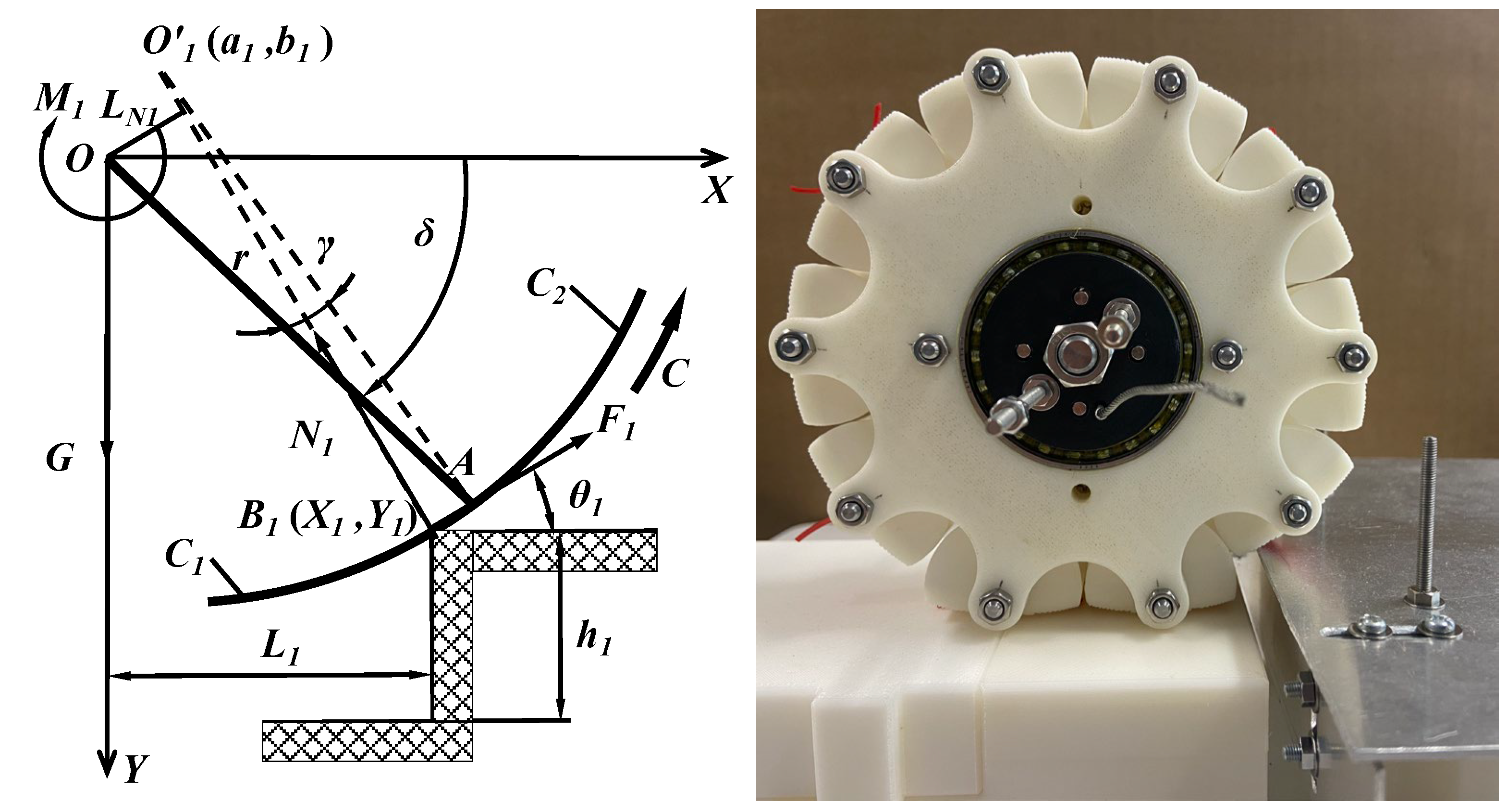
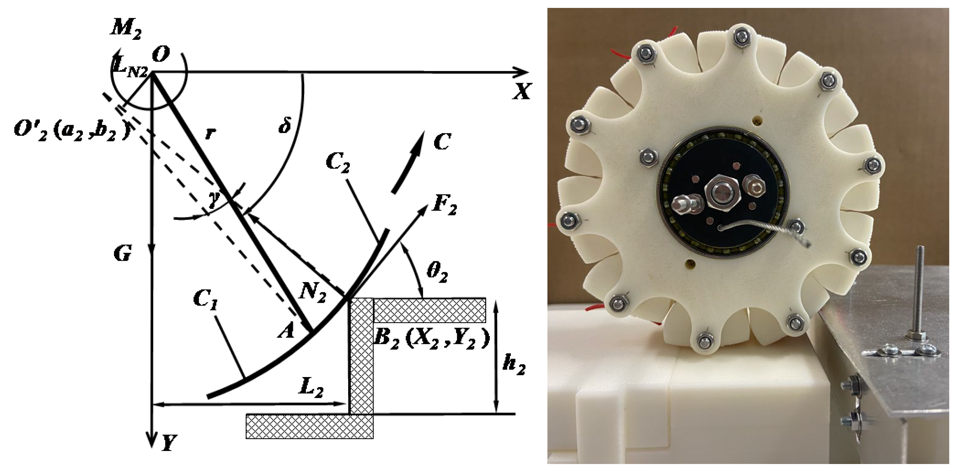
3.2.2. Mechanical Analysis of Contact Obstacle Surmounting in Section C2
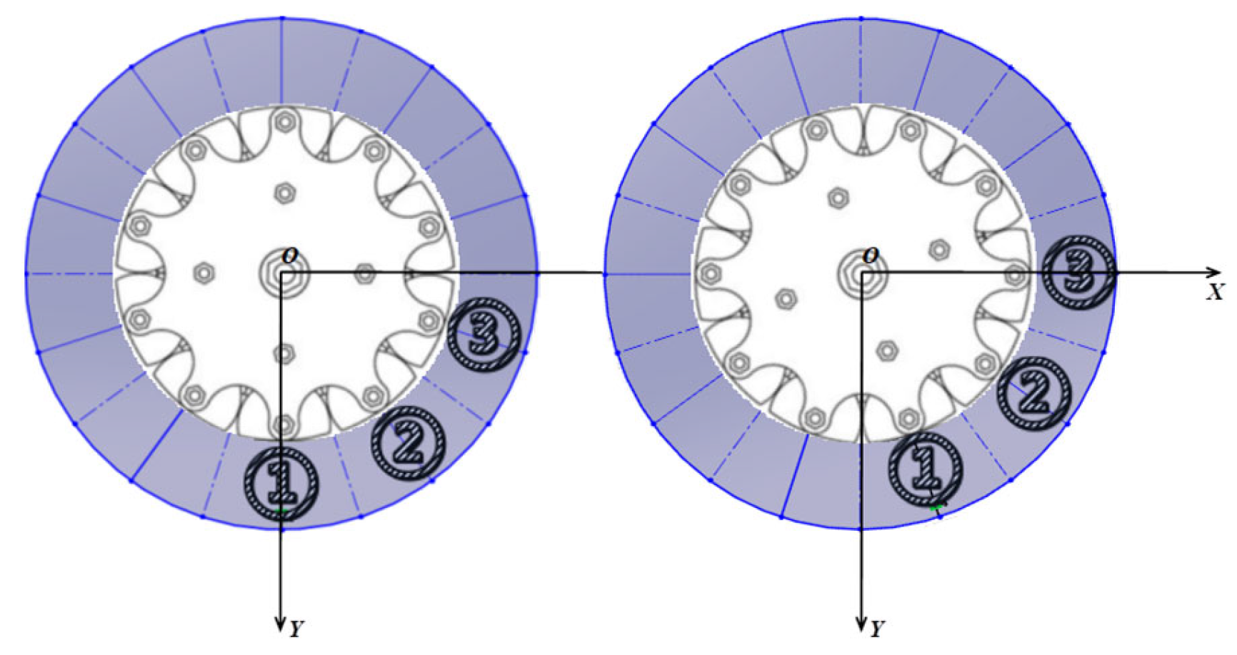
3.3. Analysis of the Transformable Wheel Obstacle Surmounting Performance
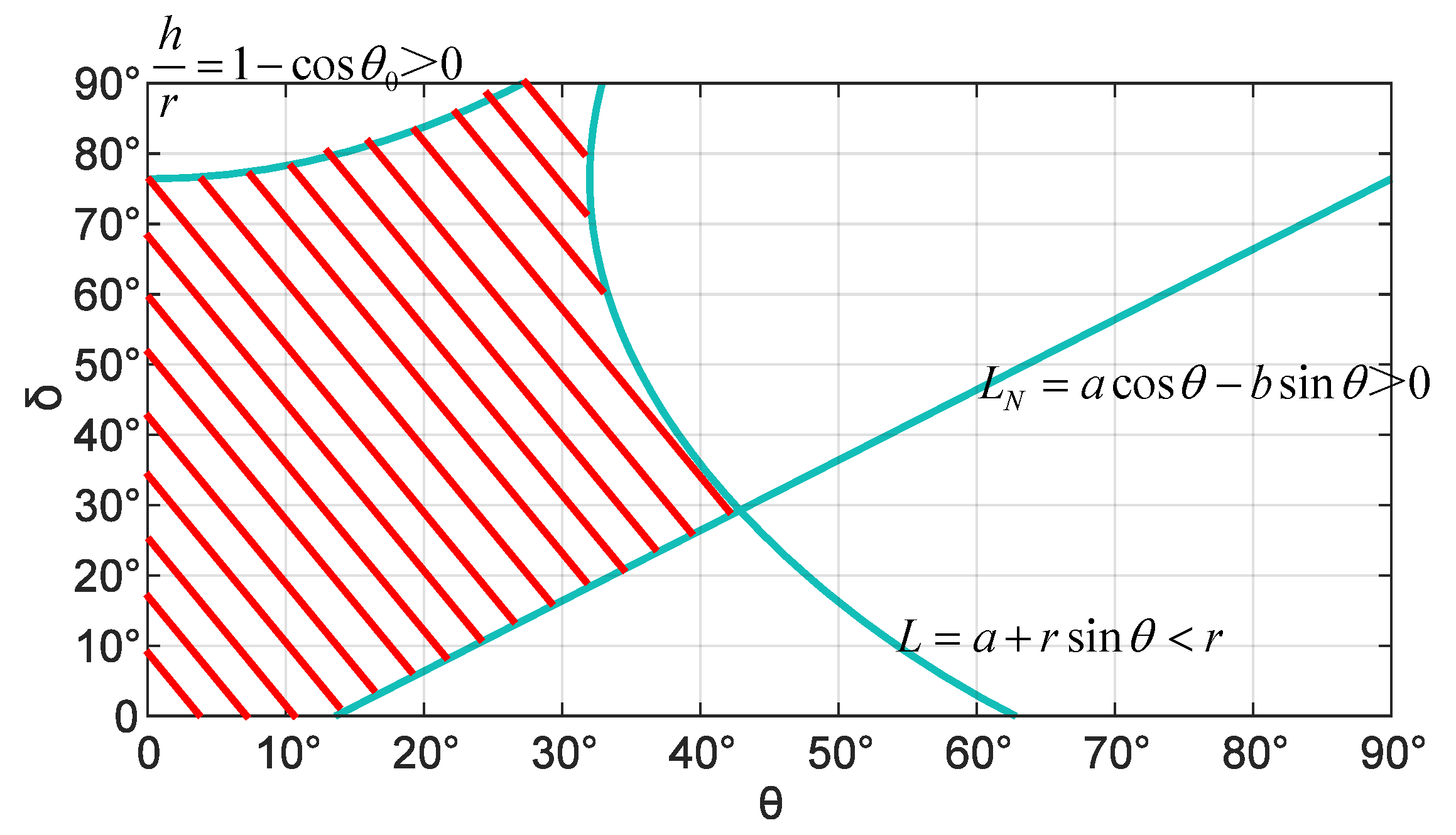
3.3.1. Value Range
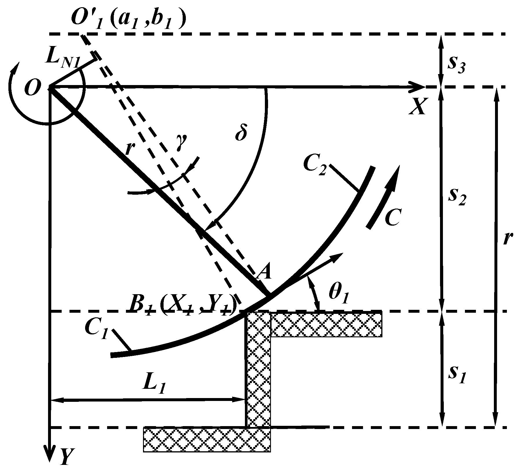
3.3.2. Theoretical Parameters
- (1)
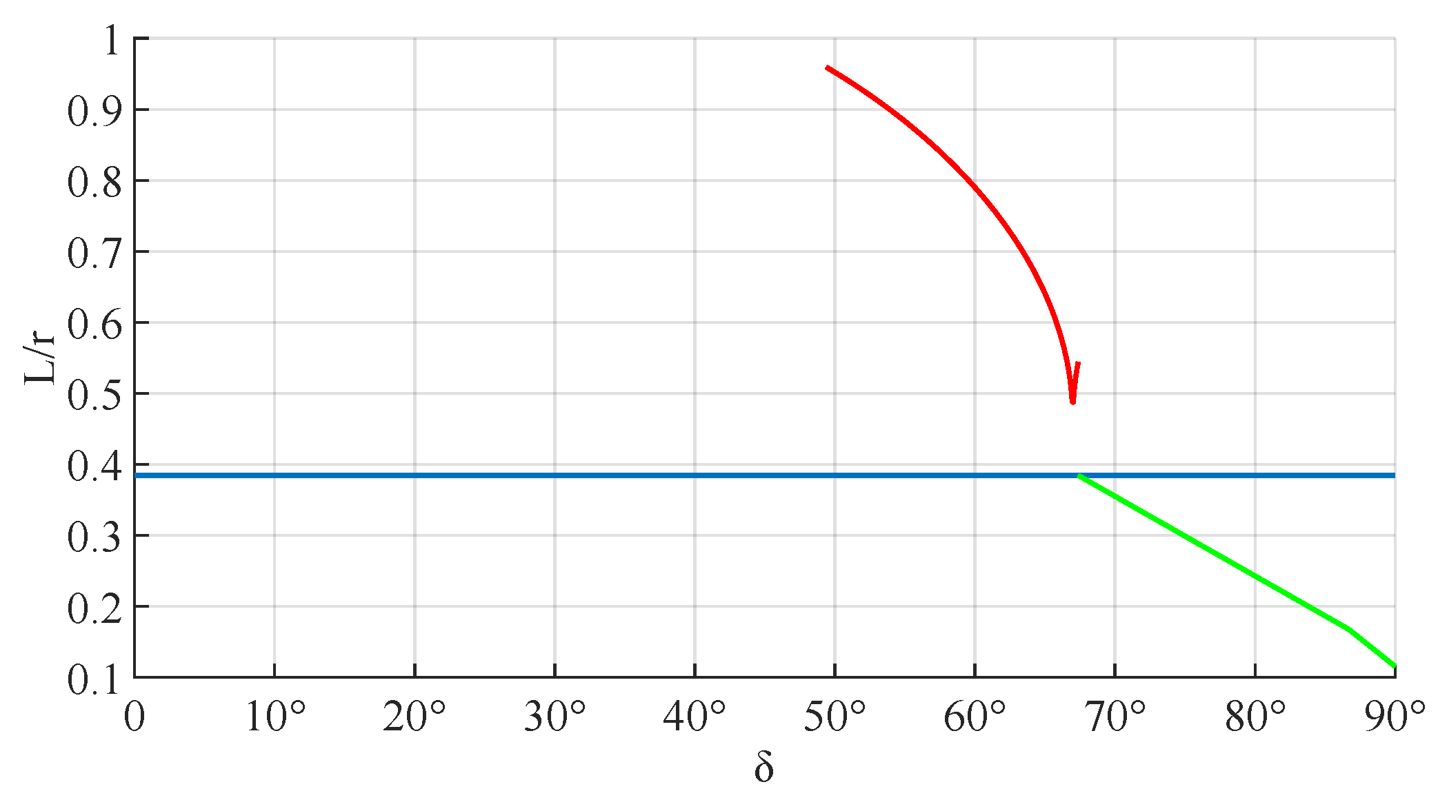
- Torque arm L
- (2)
- Wheel torque M
- (3)
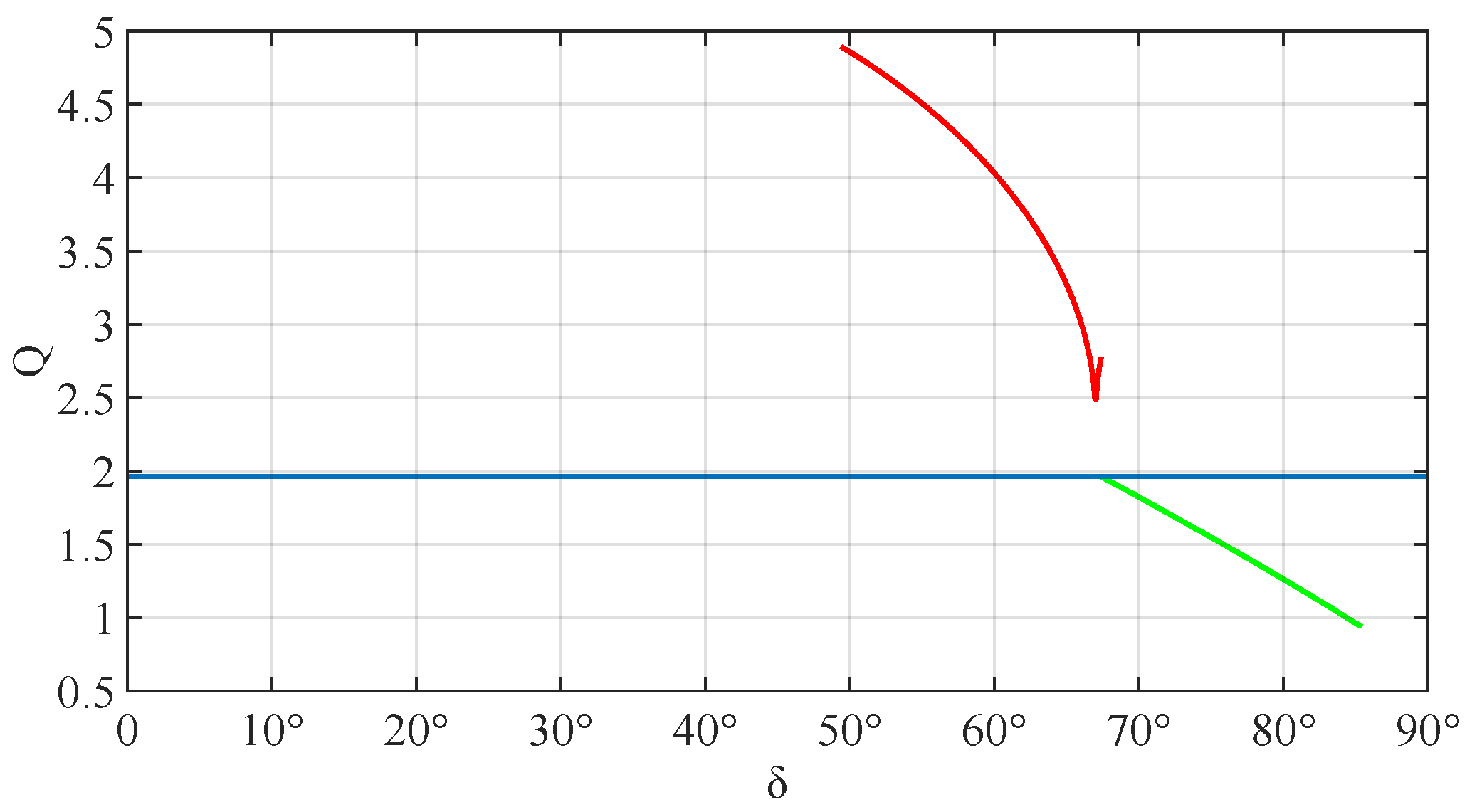
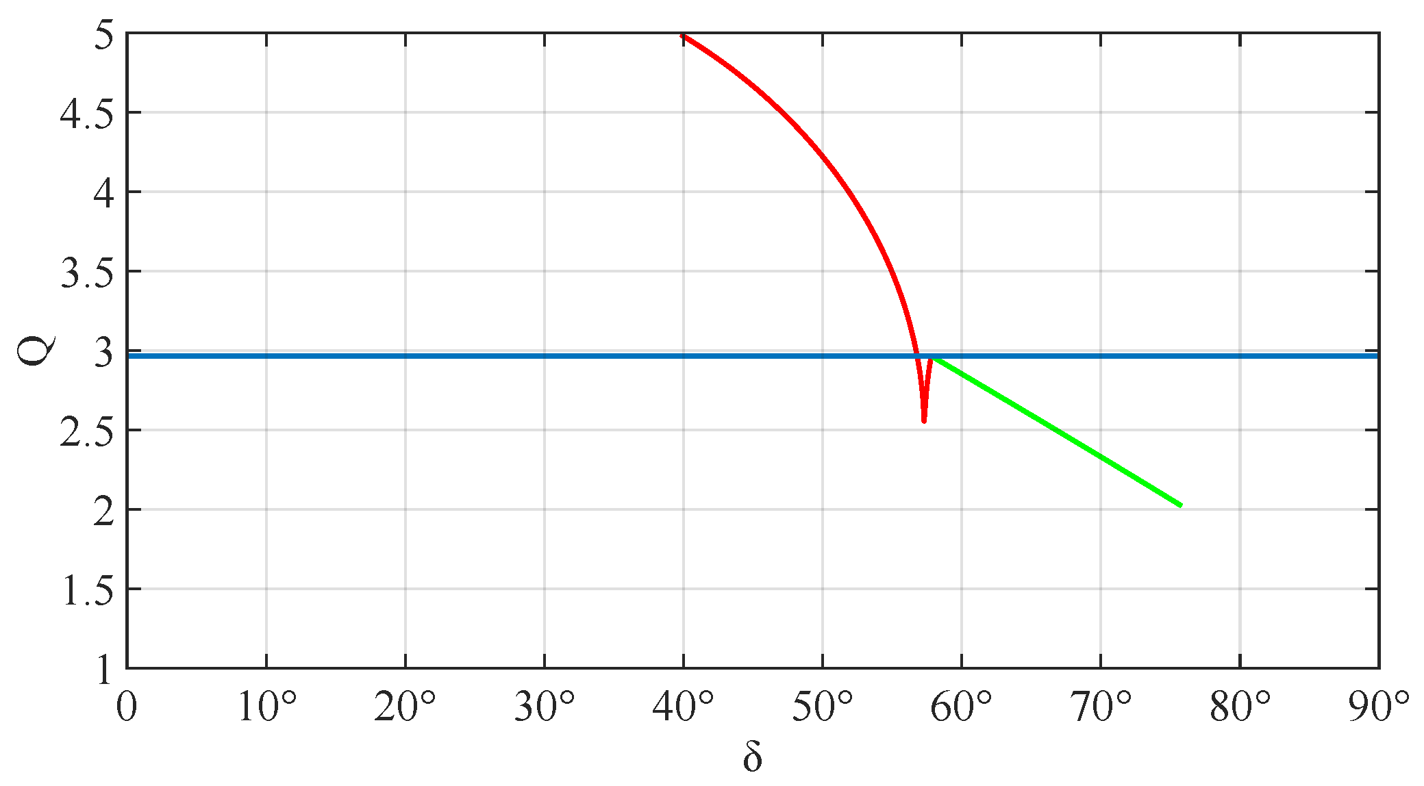
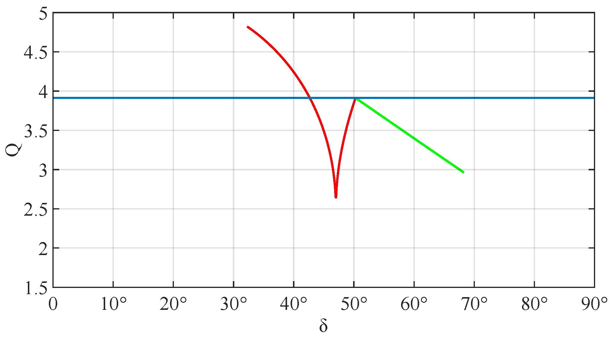
- Drive force Q
4. Conclusions
Author Contributions
Funding
Institutional Review Board Statement
Informed Consent Statement
Data Availability Statement
Acknowledgments
Conflicts of Interest
References
- Yamaga, S. Urbanization in the suburbs. Geosci. Mag. 1960, 69, 187–199. [Google Scholar]
- Wilmoth, J.R. Increase of human longevity: Past, present, and future. Jpn. J. Popul. 2011, 9, 155–161. [Google Scholar]
- Japan Cabinet Office. Linghe 2-Year White Paper on Aging Society. Available online: https://www8.cao.go.jp/kourei/whitepaper/w-2020/html/zenbun/index.html (accessed on 18 August 2022).
- Japan Cabinet Office. Heisei 24 Years, Explanation of Social Countermeasures for the Elderly. Aging Society Forum in Tokyo. Available online: https://www8.cao.go.jp/kourei/kou-kei/24forum/tokyo-s3.html (accessed on 18 August 2022).
- Zhang, C.; Liu, T.; Song, S.; Wang, J.; Meng, M.Q. Dynamic wheeled motion control of wheel-biped transformable robots. Biomim. Intell. Robot. 2022, 2, 100027. [Google Scholar] [CrossRef]
- Schroer, R.T.; Boggess, M.J.; Bachmann, R.J.; Quinn, R.D.; Ritzmann, R.E. Comparing cockroach and whegs robot body motions. In Proceedings of the IEEE International Conference on Robotics and Automation, New Orleans, LA, USA, 26 April–1 May 2004; pp. 3288–3293. [Google Scholar]
- Nagatani, K.; Kuze, M.; Yoshida, K. Development of transformable mobile robot with mechanism of variable wheel diameter. J. Robot. Mechatron. 2007, 19, 252–257. [Google Scholar] [CrossRef]
- Zarrouk, D.; Yehezkel, L. Rising STAR: A highly reconfigurable sprawl tuned robot. IEEE Robot. Autom. Lett. 2018, 3, 1888–1895. [Google Scholar] [CrossRef]
- Clark, A.J.; Cissell, K.A.; Moore, J.M. Evolving controllers for a transformable wheel mobile robot. Complexity 2018, 2018, 7692042. [Google Scholar] [CrossRef]
- She, Y.; Hurd, C.J.; Su, H. A transformable wheel robot with a passive leg. In Proceedings of the 2015 IEEE/RSJ International Conference on Intelligent Robots and Systems (IROS), Hamburg, Germany, 28 September–2 October 2015; pp. 4165–4170. [Google Scholar]
- Kim, Y.S.; Jung, G.P.; Kim, H.; Cho, K.J.; Chu, C.N. Wheel transformer: A wheel-leg hybrid robot with passive transformable wheels. IEEE Trans. Robot. 2014, 30, 1487–1498. [Google Scholar] [CrossRef]
- Ayumu, K. Mechanism design of transformable pivoting-head wheels running over steps in life-space. In Proceedings of the International Academic Conference on Recent Advances in Engineering and Technology, SCIENCE GLOBE, Online, 3 March 2022; pp. 32–37. [Google Scholar]
- Chen, J.; Lan, F.; Wang, W. Computer simulation and trial research on surmounting obstacles ability of a front-wheel driving vehicle. Nonferrous Met. 1996, 48, 1–6. [Google Scholar]
- Chengxin, S. Theory Foundation of Automobile; China Communications Press: Beijing, China, 1990; pp. 86–94. [Google Scholar]
- Pengcheng, G. Research and design of the transformable wheel adapting to complex conditions. J. Mach. Des. 2015, 32, 41–46. [Google Scholar]
- Deng, Z.; Gao, H.; Wang, S.; Hu, M. Analysis of climbing obstacle capability of lunar rover with planetary wheel. J. Beijing Univ. Aeronaut. Astronaut. 2004, 30, 197–201. [Google Scholar]
- Diansheng, C.; Yu, H.; Tianmiao, W. Obstacle climbing analysis and simulation of wheel-legged robot. J. Beijing Univ. Aeronaut. Astronaut. 2009, 3, 371–375. [Google Scholar]
- Woolley, R.; Timmis, J.; Tyrrell, A.M.C. Transformable Wheg robot traversing stepped and sloped environments. Robotics 2021, 10, 104. [Google Scholar] [CrossRef]


| Symbols | Description | Symbols | Description |
|---|---|---|---|
| r | Radius of round wheel | h | Stair height |
| A | Rotation point of segment | B | Contact point |
| N | Pressure on a segment part | F | Friction on a segment part |
| MN | Pressure torque | MF | Friction torque |
| M | Wheel torque | L | Distance from the center of the rotation shaft to the stair |
| a | The abscissa of the center of the transformable wheel | b | The ordinate of the center of the transformable wheel |
| X | The abscissa of the center of the contact point | Y | The ordinate of the center of the contact point |
| θ0 | The angle within friction and stair | γ | The rotation angle of segment center |
| δ | The angle between OA and X axis | Q | Drive force |
| h/mm | C1 | C2 | h/mm | C1 | C2 | h/mm | C1 | C2 | h/mm | C1 | C2 | h/mm | C1 | C2 |
|---|---|---|---|---|---|---|---|---|---|---|---|---|---|---|
| 1 | 14 | 27 | 40 | 53 | ||||||||||
| 2 | 15 | 28 | 41 | 54 | ||||||||||
| 3 | 16 | 29 | 42 | 55 | ||||||||||
| 4 | 17 | 30 | 43 | 56 | ||||||||||
| 5 | 18 | 31 | 44 | 57 | ||||||||||
| 6 | 19 | 32 | 45 | 58 | ||||||||||
| 7 | 20 | 33 | 46 | 59 | ||||||||||
| 8 | 21 | 34 | 47 | 60 | ||||||||||
| 9 | 22 | 35 | 48 | 61 | ||||||||||
| 10 | 23 | 36 | 49 | 62 | ||||||||||
| 11 | 24 | 37 | 50 | 63 | ||||||||||
| 12 | 25 | 38 | 51 | 64 | ||||||||||
| 13 | 26 | 39 | 52 | 65 |
| Step Overcoming Force in Wheeled State [N] | Step Overcoming Force in Transformable State [N] | ||||||||||||
|---|---|---|---|---|---|---|---|---|---|---|---|---|---|
| 1st | 2nd | 3rd | 4th | 5th | Avg. | 1st | 2nd | 3rd | 4th | 5th | Avg. | ||
| Step height [mm] | 0 | 0.72 | 0.58 | 0.58 | 0.50 | 0.52 | 0.58 | 1.68 | 1.71 | 1.65 | 1.71 | 1.73 | 1.70 |
| 1 | 0.88 | 0.81 | 0.58 | 0.85 | 0.69 | 0.76 | 1.78 | 1.78 | 1.74 | 1.89 | 1.78 | 1.79 | |
| 2 | 1.01 | 0.98 | 1.17 | 1.20 | 1.32 | 1.14 | 1.90 | 1.94 | 1.94 | 1.84 | 1.87 | 1.90 | |
| 3 | 1.48 | 1.47 | 1.52 | 1.49 | 1.65 | 1.52 | 1.78 | 1.95 | 1.87 | 1.86 | 2.12 | 1.92 | |
| 4 | 1.68 | 1.75 | 1.61 | 1.81 | 1.80 | 1.73 | 2.06 | 2.18 | 2.05 | 1.91 | 2.20 | 2.08 | |
| 5 | 2.00 | 1.94 | 2.12 | 2.06 | 2.03 | 2.03 | 2.34 | 2.15 | 2.28 | 2.08 | 1.93 | 2.16 | |
| 6 | 2.21 | 2.18 | 2.08 | 2.16 | 2.19 | 2.16 | 2.21 | 2.15 | 2.45 | 2.43 | 2.11 | 2.27 | |
| 7 | 2.28 | 2.38 | 2.40 | 2.14 | 2.27 | 2.29 | 2.17 | 2.57 | 2.25 | 2.59 | 2.30 | 2.38 | |
| 8 | 2.56 | 2.51 | 2.48 | 2.43 | 2.31 | 2.46 | 2.40 | 2.44 | 2.58 | 2.64 | 2.70 | 2.55 | |
| 9 | 2.79 | 2.81 | 2.72 | 2.83 | 2.77 | 2.78 | 2.86 | 2.80 | 2.77 | 2.60 | 2.48 | 2.70 | |
| 10 | 2.84 | 2.99 | 2.96 | 2.94 | 2.90 | 2.93 | 2.81 | 2.91 | 2.95 | 2.77 | 2.61 | 2.81 | |
| 11 | 3.09 | 3.02 | 3.06 | 2.98 | 3.14 | 3.06 | 3.09 | 2.70 | 3.22 | 3.19 | 2.65 | 2.97 | |
| 12 | 3.51 | 3.21 | 3.16 | 3.26 | 3.15 | 3.26 | 3.30 | 3.08 | 2.53 | 3.26 | 2.67 | 2.97 | |
| 13 | 3.51 | 3.30 | 3.17 | 3.42 | 3.36 | 3.35 | 3.38 | 3.26 | 2.76 | 3.32 | 3.14 | 3.17 | |
| 14 | 3.46 | 3.42 | 3.61 | 3.59 | 3.45 | 3.51 | 3.34 | 3.35 | 2.81 | 3.33 | 2.91 | 3.15 | |
| 15 | 3.63 | 3.67 | 3.58 | 3.61 | 3.53 | 3.60 | 3.35 | 3.40 | 2.90 | 3.47 | 2.98 | 3.22 | |
Disclaimer/Publisher’s Note: The statements, opinions and data contained in all publications are solely those of the individual author(s) and contributor(s) and not of MDPI and/or the editor(s). MDPI and/or the editor(s) disclaim responsibility for any injury to people or property resulting from any ideas, methods, instructions or products referred to in the content. |
© 2023 by the authors. Licensee MDPI, Basel, Switzerland. This article is an open access article distributed under the terms and conditions of the Creative Commons Attribution (CC BY) license (https://creativecommons.org/licenses/by/4.0/).
Share and Cite
Chen, Y.; Kamioka, A.; Iwase, M.; Inoue, J.; Satoh, Y. Design and Analysis of Transformable Wheel with Pivoting-Head Mechanism. Appl. Mech. 2023, 4, 70-89. https://doi.org/10.3390/applmech4010005
Chen Y, Kamioka A, Iwase M, Inoue J, Satoh Y. Design and Analysis of Transformable Wheel with Pivoting-Head Mechanism. Applied Mechanics. 2023; 4(1):70-89. https://doi.org/10.3390/applmech4010005
Chicago/Turabian StyleChen, Yaowei, Ayumu Kamioka, Masami Iwase, Jun Inoue, and Yasuyuki Satoh. 2023. "Design and Analysis of Transformable Wheel with Pivoting-Head Mechanism" Applied Mechanics 4, no. 1: 70-89. https://doi.org/10.3390/applmech4010005