Free-Form Deformation Parameterization on the Aerodynamic Optimization of Morphing Trailing Edge


Laboratory of Applied Research in Active Controls, Avionics and Aeroservoelasticity (LARCASE), École de Technologie Supérieure, Université du Québec, Montreal, QC H3C-1K3, Canada
*
Author to whom correspondence should be addressed.
Appl. Mech. 2023, 4(1), 304-316; https://doi.org/10.3390/applmech4010017
Submission received: 1 February 2023
/
Revised: 16 February 2023
/
Accepted: 22 February 2023
/
Published: 28 February 2023
(This article belongs to the Special Issue Feature Papers in Fluid Mechanics)
Abstract
:Every aerodynamic optimization is proceeded by a parameterization of the studied aerial object, and due to its influence on the final optimization process, careful attention should be made in choosing the appropriate parameterization method. An aerodynamic optimization of a morphing trailing edge is performed using a free-form deformation parameterization technique with the purpose of examining the influence of the initial conditions of the parameterization on the optimization results, namely on the number of control points. High-fidelity gradient-based optimization using the discrete adjoint method is established by the coupling of OpenFOAM and Python within the DAFoam optimization framework. The results indicate that the number of control points has a considerable effect on the optimization process, in particular on the convergence, objective function value, and on the deformation feasibility.
1. Introduction
Aerodynamic shape optimization has recently been the focus of many studies in the field of aeronautics, due to its significant contribution in the improvement of aircraft and unmanned aerial vehicle (UAV) performance. In the aerodynamic shape optimization, the choice of an adequate parameterization method to change the wing shape is of paramount importance before the start of the optimization process, meaning that the more realistically the wing shape can be parametrized, the more accurate and robust the optimization results are. The overall optimization process, including its computation time, robustness, and solution precision are strongly dependent upon the chosen parameterization technique [1].
The optimization process, whether it has one-objective or a multi-objective [2,3], is always linked with how the optimizing model is defined or parametrized mathematically. A successful parameterization method is characterized by its ability to cover a large design space using a limited set of design variables [4]. Shape parameterization methodology is divided into two categories: “constructive” and “deformative”. In constructive methods, a wing is generated using a series of specified parameters, while in deformative methods, such as free-form deformation, a wing is generated by changing its initial shape.
In a comparative study, Sripawadkul et al. [5] compared five constructive parameterization methods: the Ferguson method, B-Splines, Class-Shape Transformation (CST), PARSEC, and Hicks–Henne bump functions. Several desired characteristics were applied as criteria to find the best parameterization method. The comparative study showed that these metrics could be applied as a basis for objective function comparison, and that the best parameterization method is dependent upon the problem at hand. A survey of shape parameterization techniques for multidisciplinary optimization was performed by Samareh [6], which was focused on the stability of the available parameterization techniques for the multidisciplinary optimization of aerospace applications of complex structures. Eight different parameterization techniques were reviewed: partial differential equations (PDEs), discrete, analytical, polynomial and spline, free-form deformation (FFDs), basis vector, and CAD-based. It was concluded that the choice of the shape of the parameterization technique depends on six criteria: the parameterization accuracy, the disciplines involved, the automatic grid generation, the optimization algorithms, the cycle time, and the CAD direct connection. In recent years, several aerodynamic optimization with different optimization algorithms and parametrization methods have been performed in the Active Control, Avionics, and AeroServoElasticity Research Laboratory (LARCASE). Table 1 shows these studies in detail.
In recent decades, morphing wing technology [15,16,17] has proven to be the main candidate to be applicable in the next generation of aircrafts; therefore, many studies, have been performed on morphing wings, due to their unquestionable benefits in improving aerodynamic efficiency. Numerous aerodynamic shape optimizations have been performed using different morphing wing approaches, including trailing edge, leading edge, upper surface, and overall wing shape morphing. Secanell et al. [18] investigated six flight conditions: stall, takeoff run, climb gradient, rate of climb, cruise, and loiter, and for each of these conditions, the morphing shape was studied through a high-fidelity aerodynamic optimization. The results showed a significant reduction in the airfoil drag coefficient on the morphing airfoil. Botez [19,20] presented recent studies conducted at the Laboratory in Active Controls, Avionics, and AeroServoElasticity (LARCASE), in which morphing wing optimization was performed with different parameterization methods and optimization algorithms. Using constructive parameterization, Koreanschi et al. [10] applied three different optimization algorithms, including a Genetic Algorithm (GA), an Artificial Bee Colony (ABC) algorithm, and a Gradient Descent algorithm for the optimization of the wings’ upper surface using the NURBS parameterization technique. Bashir et al. [11] performed an aerodynamic shape optimization for the morphing leading edge (drooped nose leading edge) using the Bezier-PARSEC parameterization method and an evolutionary Particle Swarm Optimization (PSO) optimization algorithm. In another study [12], the CST parameterization method was implemented on a morphing leading edge by adding local shape changes. However, in the optimization of the whole wing section, the whole aircraft or UAV constructive parameterization methods may lose their efficiency, since in these problems, the number of design variables, unlike in two-dimensional cases, are of the order of one hundred or more. For this reason, deformative techniques, such as CAD-based models or the free-form deformation (FFD) technique are recommended for the optimization of 3D wings or whole aircraft, based on [21,22,23], as these techniques have been proven to be efficient because of their flexibility in solving problems with a high number of design variables of the order of .
Many optimization problems that use the FFD technique for the optimization of the whole wing and aircraft are available. He et al. [24] applied the FFD parameterization technique on UAV and Common Research Model (CRM) wings, using 127 and 201 design variables, respectively. In a subsequent study [25], they applied the FFD parameterization method in the optimization of an Ahmed body and of a full model car.
In [26], a CRM Wing–Body–Tail (whole aircraft), with a total of 227 design variables, a blended tube, and a turbine blade, was also parametrized with the FFD technique. Based on these studies, the FFD technique is the most feasible methodology for solving problems with a high number of design variables.
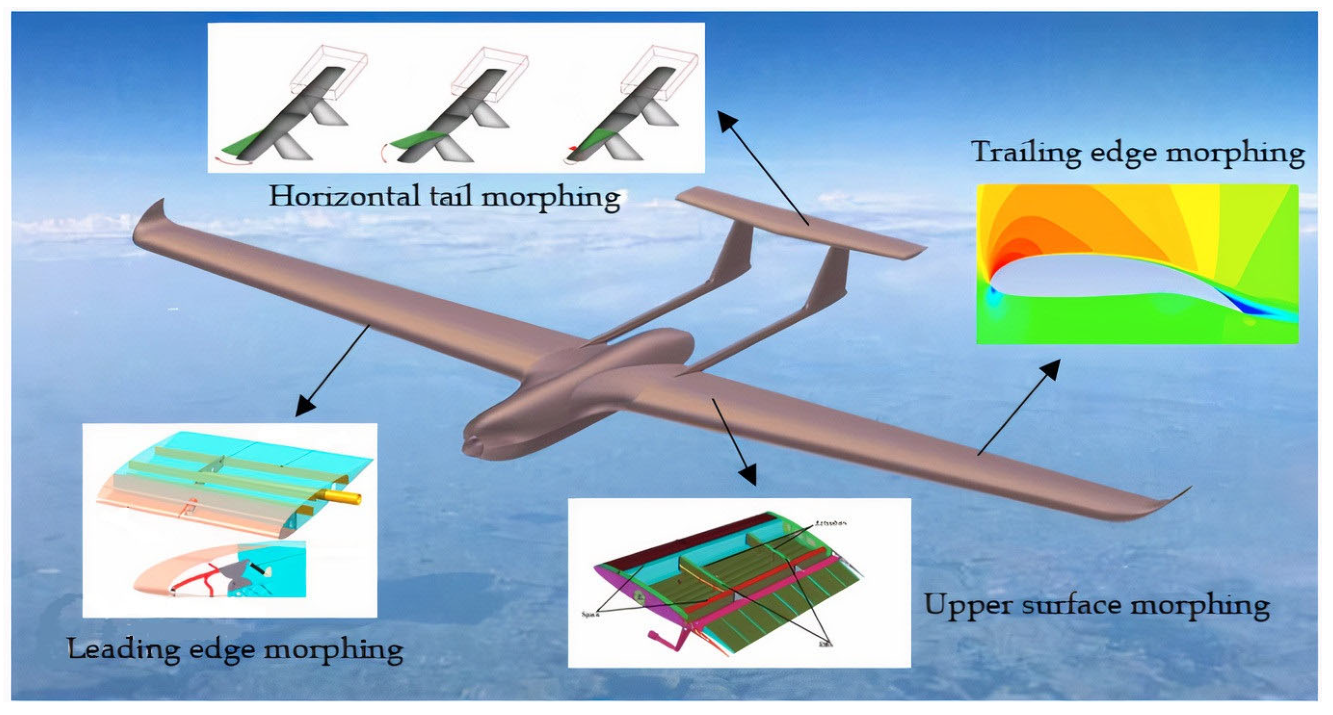
In the present study, an aerodynamic shape optimization is performed on the morphing trailing edge. Among the morphing configurations, the trailing edge morphing is the most commonly studied, due to its conspicuous influence on flight performance, especially in cruise flight. Numerous studies from aerodynamic [27,28], structural [29,30], and aeroelastic [31] aspects of this morphing configuration have been studied in recent years. In this study, we optimize the morphing trailing edge of the UAS-S45 wing using the FFD parameterization technique. The UAS-S45 is a surveillance unmanned aerial system designed and manufactured by Hydra Technologies in Mexico. A complete aerodynamic model of this UAS-S45 is presented in [32,33]. Figure 1 shows the UAS-S45 with different morphing configurations obtained from studies conducted at the LARCASE.
This study is performed using a high-fidelity optimization framework. To the best of the authors’ knowledge, most of the optimization problems in the literature on morphing wings have been conducted using low-fidelity aerodynamic optimization tools, such as XFoil. This study utilizes a high-fidelity optimization tool, the DAFoam optimization framework [26]; however, the main focus of this study is on the parameterization using the FFD technique, with the objective of obtaining optimization results by enhancing the accuracy of parameterization before the optimization process. In the FFD parameterization, the number of control points has a direct impact on the design of the optimization problem, meaning that it affects the fidelity of the final design. Therefore, in this paper, the FFD parameterization flexibility in terms of the number of control points is considered. Too few control points (depending on the case studied) will cause some parameters of the design space, such as displacement magnitude, to be neglected and will also cause premature local convergence and inaccurate mesh deformation, while too many design points will cause mesh overlap and a longer optimization process, and thus, higher computation cost. Therefore, it is important to find the correct number of control points before starting the optimization problem. Basically, in FFD parametrization, the number of control points is determined by trial-and-error since there is no direct method to find the exact number of control points. This study is conducted to show the FFD control points flexibility and to compare the results obtained for different number of control points and their influences on the results obtained following the optimization process of a morphing airfoil. This study ensures the validation of the optimization results before starting the optimization; this process could be extended to any optimization problem conducted with the FFD parameterization technique.
2. Methodology
2.1. FFD Parameterization Technique
The FFD parameterization technique was first proposed by Sederberg and Parry [34]. They introduced a new way to modify a solid model, so that its volume remains the same. Their mapping scheme was based on tri-variate Bernstein polynomials with control points being their coefficients. Since then, the mapping scheme has since evolved to use tri-variate Bezier, B-spline, or NURBS polynomials. In this mapping technique, the geometry of any size is embedded inside a lattice, called FFD block, with its corresponding control points. The lattice consists of B-spline control points, which, when altered, deform the shape of embedded body. The number of control points and their displacements are dependent upon the geometry and the deformation zone. In Equation (1), the Newton’s method is used to map the parameter space into physical space, while the embedded object, which is inside a cartesian space, is mapped into the initial tri-variate B-spline volume [35]:
where is the vertices of the initial embedded object , , and , which is the B-spline basis functions of degree , , and , and is the initial deformation lattice.
The basic functions are calculated in Equation (2):
and
After the deformation, the B-spline volume, calculated in Equation (1) is substituted by a new B-spline volume with control points , which leads to Equation (3):
where represents the object’s vertices after deformation.
Since FFD blocks parameterize the geometry variations rather than the geometry itself, it is therefore only necessary to use a set of design variables that span the desired geometry modification [36].
As the FFD blocks are represented by tri-variate B-spline volumes, the sensitivity of any point inside the volumes can be calculated according to Equation (4).
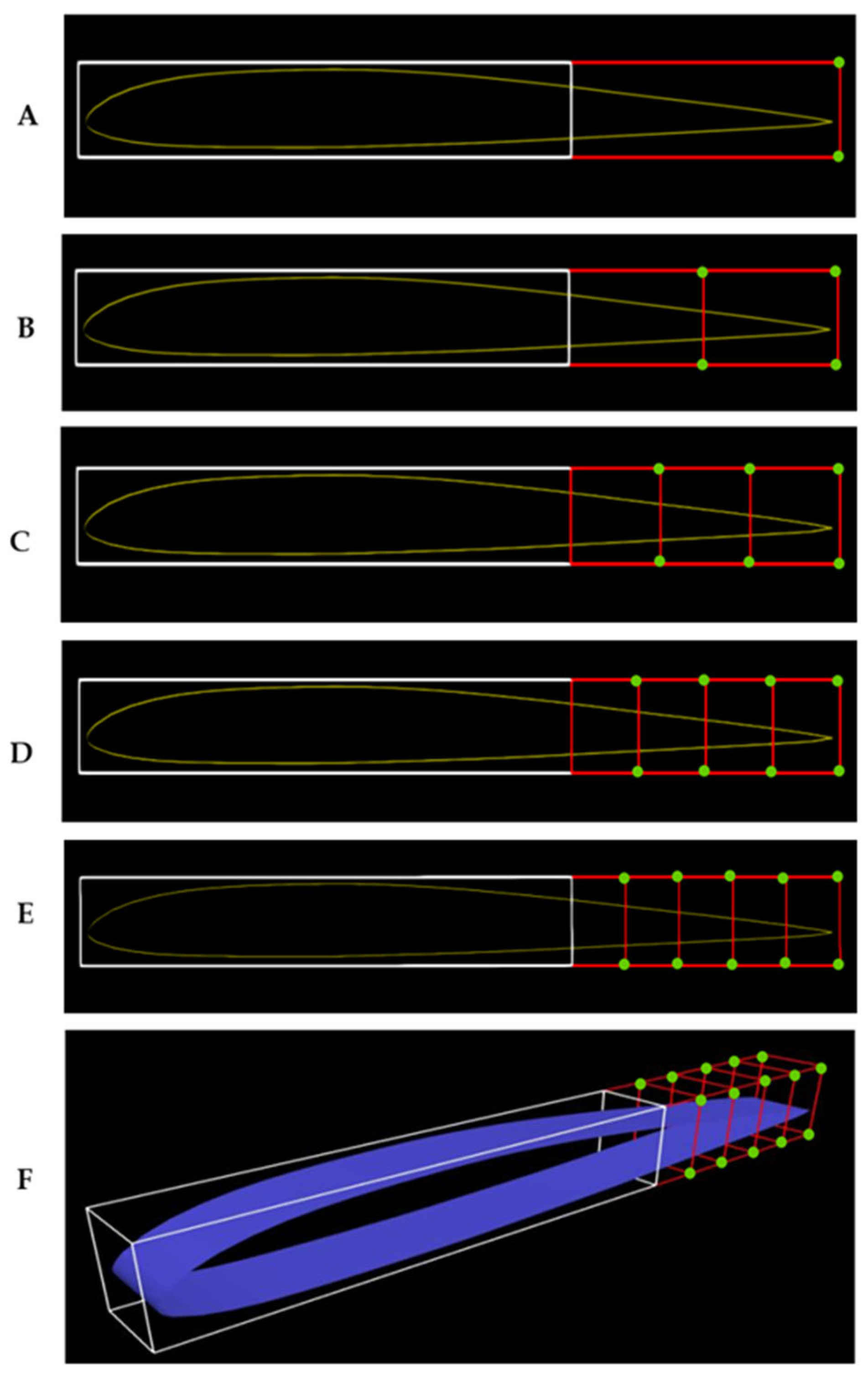
where is the spatial coordinates of the embedded points, is the design variables, and is the spatial coordinates of the FFD block control points. In Equation (4), shows the derivatives of control points’ motion with respect to the actual design variables, and is the shape function. In this study, to examine the FFD parameterization in terms of number of control points, five sets of FFD blocks with different numbers of control points for the same block topology and the same morphing configuration are examined. Figure 2 shows the S-45 airfoil embedded inside the FFD block. Two FFD blocks are used, one for the undeformed part (white block: 70% of the chord length) and one for its morphing trailing edge (red block: 30% of the chord length). As depicted in Figure 2, the control points shown in green are the ones that are free to move in a vertical downward direction, while the rest of them (the ones without color) are constrained to zero movement in every direction.
2.2. DAFoam Optimization Framework
For large-scale optimization problems on an aircraft’s wing or a whole aircraft, gradient-based optimization is an efficient tool, as it is capable of locally finding a set of design variables to maximize the aircraft’s performance. By using this optimization tool, DAFoam is capable of handling large-scale optimization problems in aerodynamics. Thus, its high-fidelity optimization framework ensures the reliability of the optimization results. In the field of aerodynamic optimization, most previous studies have used low-fidelity optimization approaches [7,8,9,10,11,12,13], in particular XFoil or XFLTR solvers, which solve the potential flow equations rather than the Reynolds-averaged Navier–Stokes (RANS) equations. However, the DAFoam optimization framework, developed in 2019 by the Multidisciplinary Design Optimization (MDO) laboratory team at Michigan University [26], is capable of handling optimization problems with many design variables by using a high-fidelity solver, namely OpenFOAM. DAFoam uses an adjoint method to compute the derivatives of design variables, thereby making the computation cost independent on the number of design variables but dependent on the number of functions of interest, which are the functions of design variables and the state variables [24]. In this optimization framework, OpenFOAM uses the RANS equations for calculating the aerodynamic parameters, and the object-oriented discrete adjoint-based optimization process in Python is coupled with OpenFOAMs steady-state solvers. For the computation of the adjoint equation, which contains the residual equations and function of interest, graph coloring is used to accelerate its calculus by dividing the Jacobian matrix into subgroups (of various colors), where the objective and residual computation routines are called only once instead of multiple times (see [37,38] for details regarding graph coloring).
2.3. Optimization Numerical Setup
This study was performed for the UAS-S45 cruise flight condition, in which the speed was taken from its operation manual. Therefore, the corresponding cruise speed for the UAS-S45 is 70 knots (28.29 m/s) and the corresponding altitude is 15,000 ft. The turbulence model is Spalart–Allmaras, where the turbulence intensity is equal to 1%. To verify that the optimization results are independent to the mesh density, three different number of elements (31,598, 117,068, and 198,758) were chosen for numerical model studies, and it was found that the error between the lowest and highest number of element results in terms of CL/CD was as low as 1.9%; therefore, the lowest number of elements was chosen for the optimization studies of all five cases. Figure 3 shows the density of elements around the airfoil with the chosen number of elements (equal to 31,598). The surfaces to which the airfoil is attached are defined as the symmetry boundary, while the rest of the domain (inlet, outlet, upper, and lower surfaces) have the InletOutlet boundary condition, a specific boundary condition in OpenFOAM. In this boundary condition, the boundary switches between “zero gradient” and “fixed value” condition, when the fluid flows out the domain and into the domain, respectively.
The optimization is performed based on the above CFD setup, where the objective function is lift-to-drag maximization and where the lift coefficient is defined as an inequality constraint function (. The minimum lift coefficient is found before the optimization process, and is used in the constraint function to prevent the lift coefficient from being lower than the minimum lift coefficient during the optimization. To have a linear deflection in the spanwise direction, a linear constraint is applied to have the same magnitude of deformation in the spanwise direction for each control point. The deflection is then constrained in a downward direction with a maximum value of 15 mm, while the deflection in the upward direction is confined to zero; therefore, the flap is only deflected in a downward direction.
To compare the results obtained from different FFD parameterization setups, four criteria are considered: optimality error, convergence time, objective function, and deformation feasibility (realistic deformation in practice). Optimality error is a criterion for the evaluation of the optimization accuracy; it shows how well the objective function could be minimized or maximized, meaning that as its value approaches to zero, it shows that the objective function is optimized to the greatest or least value possible, which gives an idea of how well the solution is converged.
2.4. Optimization Process for a Morphing Trailing Edge Flap
The optimization is performed in this research using a gradient-based optimization that uses a discrete-adjoint method. OpenFOAM is used as the flow solver, while the generation of the FFD block and the optimization algorithm are conducted in Python. In this study, the optimization is performed to solve a non-linear problem with continuous constraints. An Interior Point Optimizer (IPOPT) is used, as it is suitable for solving non-linear programming problems with continuous constraints by minimizing or maximizing the objective function that is subjected to several constrained functions, as follows:
where is the objective function, is the constrained function, x is the design variables, and and represent the lower and upper bounds, respectively.
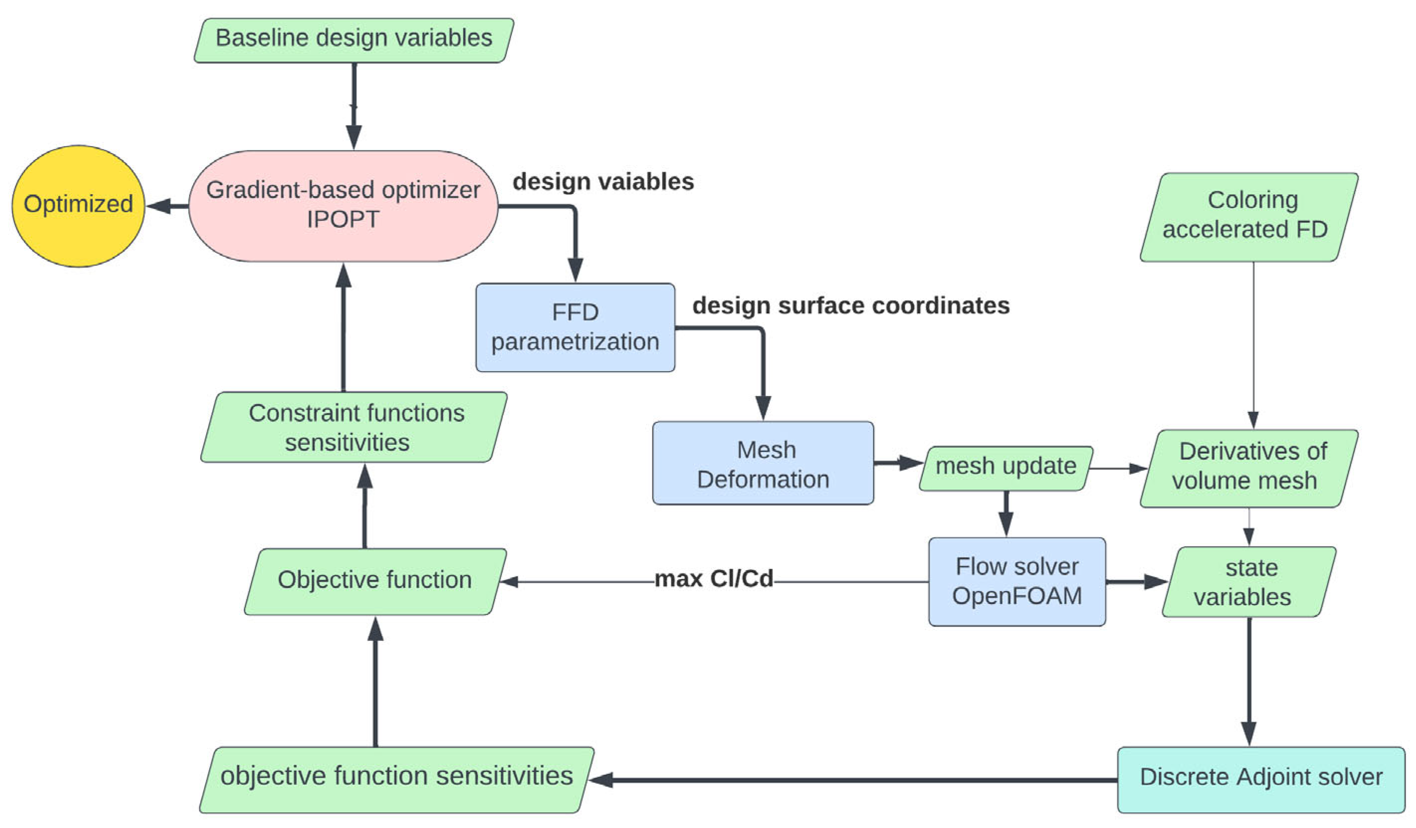
IPOPT uses filter methods with line search, and the first and second derivatives of the functions of interest, Jacobians, and Hessians, respectively, are obtained using the Automatic Differentiation (AD) method; however, the Hessian matrix does not need to be calculated, since in cases when the second derivatives are not available, the quasi-Newton methods are used, such as Broyden–Fletcher–Goldfarb–Shanno algorithm (BFGS). The approach used in this study is the trailing edge morphing for the UAS-S45 with the objective function of lift-to-drag maximization. FFD parameterization is applied to this morphing wing configuration, and different criteria, as mentioned in the first section, are analyzed based on the results obtained from the optimization results. Figure 3 shows the overall optimization process needed to solve this problem, while Table 2 shows the optimization setup for the UAS-S45 airfoil with morphing trailing edge (MTE). In this study, five cases were optimized, which were distinct in terms of the number of control points on the trailing edge. The minimum number of control points belongs to case 1, with 8 control points, and the maximum number belongs to case 5 with 24 control points (Table 2). Figure 4 shows the overall optimization process in this study.
The optimization is performed based on the above CFD setup, where the objective function is lift-to-drag maximization and where the lift coefficient is defined as an inequality constraint function (. The minimum lift coefficient is found before the optimization process and is used in the constraint function to prevent the lift coefficient from being lower than the minimum lift coefficient during the optimization. To have a linear deflection in the spanwise direction, a linear constraint is applied to have the same magnitude of deformation in the spanwise direction for each control point. The deflection is then constrained in a downward direction with a maximum value of 15 mm, while the deflection in the upward direction is confined to zero; therefore, the flap is only deflected in a downward direction.
3. Results and Discussion
The optimization results are compared for five cases, in which different number of control points are considered. Various criteria, including convergence time, number of iterations, optimality error, and objective function values are compared for different number of control points. Figure 5A,B shows the optimality error of the optimization process for each case. In Figure 4A, it can be seen that for the cases 1 to 3, where the number of control points are lower than for cases 4 and 5, the convergence is reached with a low number of iterations and is of the order of . However, for cases 4 and 5 (Figure 5B), a satisfactory convergence is not achieved even after 50 iterations and is of order of and for cases 4 and 5, respectively. Table 3 shows the comparison of five cases in terms of the convergence time, number of iterations, optimality, and .
As shown in Table 3, as the number of control points increases, the number of iterations, computation time, and optimality error increase, thus leading to inaccurate results. By considering the objective function, the maximum value of the lift-to-drag ratio is obtained in case 3, which corresponds to a 13.8% improvement. If all criteria are considered, it is obvious that case 3 with eight control points gives the best results in terms of optimality error, convergence time, and Cl/Cd maximization (objective function).
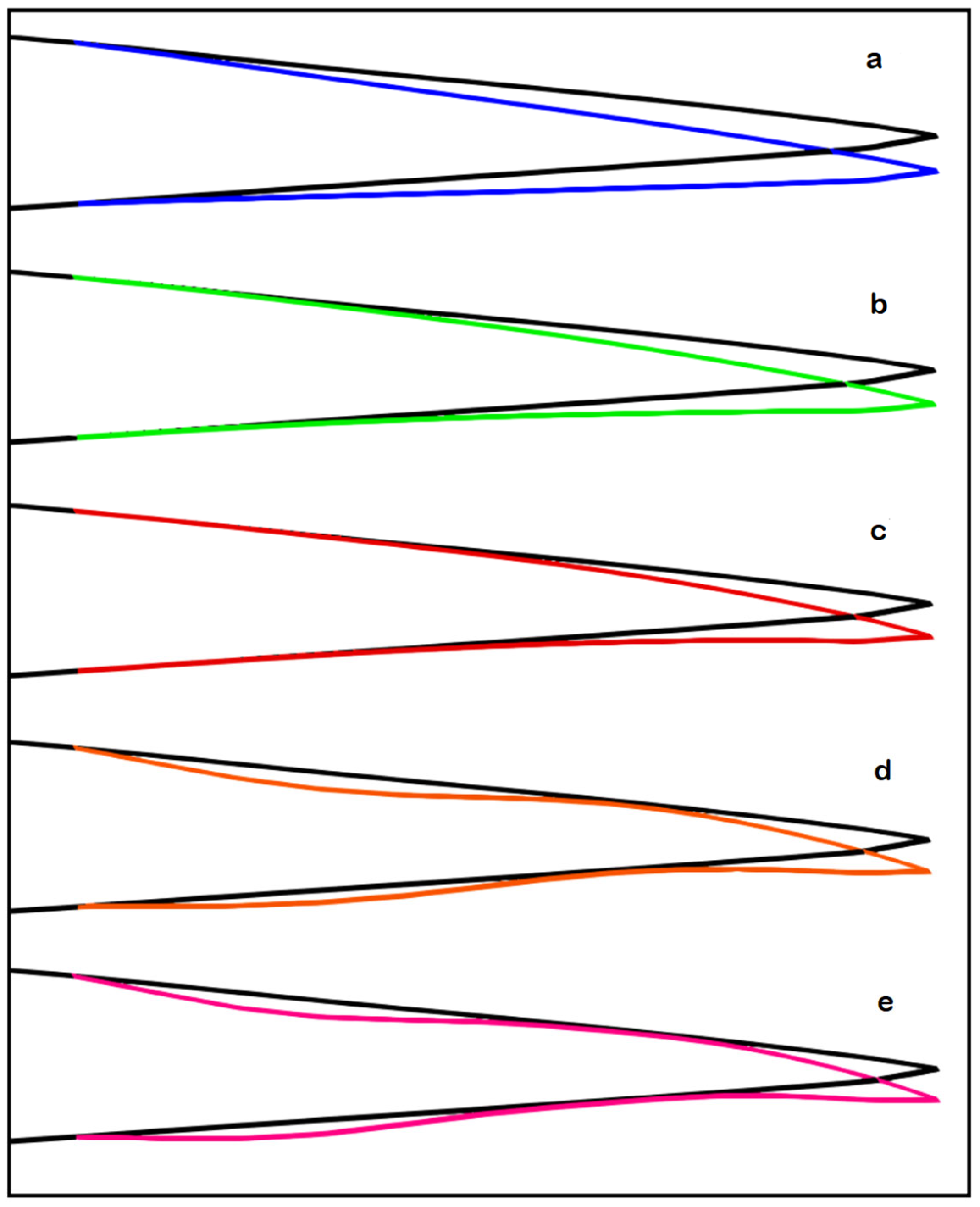
Figure 6 shows the UAS-S45 airfoil after the morphing trailing edge optimization for all five cases. In case 1, the one with the least number of control points (six), there is a sharp bending of the trailing edge, similar to that of a hinged flap, but, as the number of control points increases, the deformation becomes smoother. However, when the control points’ number exceeds eight (cases 4 and 5), the trailing edge smooth deformation turns into a wavy-type deformation (Figure 6). Therefore, case 3 is the best case in terms of deformation feasibility.
4. Conclusions
A high-fidelity aerodynamic optimization of a morphing trailing edge was performed in this study using a free-form deformation parameterization. The study was conducted for five different cases, which were each distinct in terms of the FFD number of control points. The main purpose of this study was to show the influence of the FFD parameterization flexibility in terms of control points and how it would affect the final optimization results. The study of five cases showed that the ultimate optimization results were directly influenced by the choice of the number of control points, where too few control points (less than six) led to unsmooth deformation and less objective function improvement. This observation means that a low number of control points restricts the morphing capability, and the geometry becomes confined. On the other hand, a higher number of control points (higher than eight) led to undesirable, wavy deformations, which are impractical from the mechanism and manufacturing perspectives; moreover, a higher number of control points did not show a very good optimization accuracy, and a satisfactory convergence was not accomplished. We have shown that the influence of the number of control points was substantial and that it had a direct impact on the optimization results. There should be a trade-off to find the optimal number of control points prior to the start of the optimization by analyzing three parameters, including the computation time, solution optimality, and the improvement rate of the objective function.
Therefore, the optimal solution was chosen based on the predefined criteria, including the objective function value, deformation feasibility, convergence time, and optimality. According to these criteria, case 3, which had a moderate number of control points, showed the best results out of five cases, with a 13.8% improvement obtained in terms of both a higher optimization accuracy and feasible deformation. Finally, it was concluded that obtaining the optimal number of control points in the FFD parameterization is of paramount importance and that careful considerations should be made before starting the optimization process, as the number of control points directly influences the optimization results. So far, no direct mathematical formulation has been proposed for the choice of the number of control points in FFD parameterization, as it is case-dependent; therefore, a trial-and-error procedure was used to find the most appropriate number of control points.
The influence of FFD lattice topology will be studied for a three-dimensional wing to analyze the impact of lattice topology on the computation of the embedded body gradients.
Author Contributions
Conceptualization; methodology, M.H.N.; software, M.H.N.; validation, M.H.N.; investigation, M.H.N.; writing—original draft preparation, M.H.N.; writing— review and editing, M.B., R.M.B.; visualization, M.H.N., M.B. and R.M.B.; supervision, R.M.B.; funding acquisition, R.M.B. All authors have read and agreed to the published version of the manuscript.
Funding
This research received no external funding.
Data Availability Statement
The data presented in this study are available on request from the corresponding author.
Acknowledgments
Special thanks are due to the Natural Sciences and Engineering Research Council of Canada (NSERC) for the Canada Research Chair Tier 1 in Aircraft Modelling and Simulation Technologies funding. We would also like to thank CREATE-UTILI Program for the financial support as well as the Hydra Technologies’ team members Carlos Ruiz, Eduardo Yakin and Alvaro Gutierrez Prado in Mexico.
Conflicts of Interest
The authors declare no conflict of interest.
References
- Khurana, M.S.; Winarto, H.; Sinha, A.K. Airfoil Geometry Parameterization through Shape Optimizer and Computational Fluid Dynamics. In Proceedings of the 46th AIAA Aerospace Sciences Meeting and Exhibit, Reno, Nevada, 7–10 January 2008; p. 295. [Google Scholar]
- Wang, C.-N.; Yang, F.-C.; Nguyen, V.T.T.; Vo, N.T.M. CFD Analysis and Optimum Design for a Centrifugal Pump Using an Effectively Artificial Intelligent Algorithm. Micromachines 2022, 13, 1208. [Google Scholar] [CrossRef] [PubMed]
- Huynh, N.T.; Nguyen, T.V.; Nguyen, Q.M. Optimum Design for the Magnification Mechanisms Employing Fuzzy Logic-ANFIS. CMC Comput. Mater. Contin. 2022, 73, 5961–5983. [Google Scholar]
- Masters, D.A.; Taylor, N.J.; Rendall, T.; Allen, C.B.; Poole, D.J. Review of Aerofoil Parameterisation Methods for Aerodynamic Shape Optimisation. In Proceedings of the 53rd AIAA Aerospace Sciences Meeting, Kissimmee, FL, USA, 5–9 January 2015. [Google Scholar] [CrossRef]
- Sripawadkul, V.; Padulo, M.; Guenov, M. A Comparison of Airfoil Shape Parameterization Techniques for Early Design Optimization. In Proceedings of the 13th AIAA/ISSMO Multidisciplinary Analysis Optimization Conference, Fort Worth, TX, USA, 13–15 September 2010; p. 9050. [Google Scholar] [CrossRef]
- Samareh, J.A. Survey of shape parameterization techniques for high-fidelity multidisciplinary shape optimization. AIAA J. 2001, 39, 877–884. [Google Scholar] [CrossRef]
- Sugar Gabor, O.; Simon, A.; Koreanschi, A.; Botez, R.M. Improving the UAS-S4 Éhecal airfoil high angles-of-attack performance characteristics using a morphing wing approach. Proc. Inst. Mech. Eng. Part G J. Aerosp. Eng. 2016, 230, 118–131. [Google Scholar] [CrossRef] [Green Version]
- Gabor, O.; Koreanschi, A.; Botez, R. Analysis of UAS-S4 Éhecatl aerodynamic performance improvement using several configurations of a morphing wing technology. Aeronaut. J. 2016, 120, 1337–1364. [Google Scholar] [CrossRef]
- Gabor, O.; Koreanschi, A.; Botez, R.M. A new non-linear vortex lattice method: Applications to wing aerodynamic optimizations. Chin. J. Aeronaut. 2016, 29, 1178–1195. [Google Scholar] [CrossRef] [Green Version]
- Koreanschi, A.; Sugar Gabor, O.; Acotto, J.; Brianchon, G.; Portier, G.; Botez, R.M.; Mamou, M.; Mebarki, Y. Optimization and Design of a Morphing Aircraft Wing Tip Demonstrator at Low Speed for Drag Reduction, Part I–Aerodynamic Optimizations Using 3 Algorithms: Genetic, Bee Colony and Gradient Descent. Chin. J. Aeronaut. 2017, 30, 149–163. [Google Scholar] [CrossRef]
- Bashir, M.; Longtin-Martel, S.; Botez, R.; Wong, T. Aerodynamic Design Optimization of a Morphing Leading Edge and Trailing Edge Airfoil–Application on the UAS-S45. Appl. Sci. 2021, 11, 1664. [Google Scholar] [CrossRef]
- Bashir, M.; Longtin-Martel, S.; Botez, R.M.; Wong, T. Optimization and Design of a Flexible Droop-Nose Leading-Edge Morphing Wing Based on a Novel Black Widow Optimization Algorithm—Part I. Designs 2022, 6, 10. [Google Scholar] [CrossRef]
- Bashir, M.; Martel, S.L.; Botez, R.M.; Wong, T. Aerodynamic Shape Optimization of Camber Morphing Airfoil based on Black Widow Optimization. In Proceedings of the AIAA SCITECH 2022 Forum, San Diego, CA, USA, 3–7 January 2022; p. 2575. [Google Scholar] [CrossRef]
- Negahban, M.H.; Bashir, M.; Botez, R.M. Aerodynamic Optimization of a Novel Synthetic Trailing Edge and Chord Elongation Morphing: Application to the UAS-S45 Airfoil. In Proceedings of the AIAA SCITECH 2023 Forum, National Harbor, MD, USA, 23–27 January 2023; p. 1582. [Google Scholar]
- Ameduri, S.; Concilio, A. Morphing wings review: Aims, challenges, and current open issues of a technology. Proc. Inst. Mech Eng. C J. Mech. Eng. Sci. 2020, 1–19. [Google Scholar] [CrossRef]
- Concilio, A.; Dimino, I.; Lecce, L.; Pecora, R. Morphing Wing Technologies—Large Commercial Aircraft and Civil Heli-Copters, 1st ed.; Butterworth-Heinemann: Oxford, UK, 2018. [Google Scholar]
- Pecora, R. Morphing wing flaps for large civil aircraft: Evolution of a smart technology across the Clean Sky program. Chin. J. Aeronaut. 2021, 34, 13–28. [Google Scholar] [CrossRef]
- Secanell, M.; Suleman, A.; Gamboa, P. Design of a Morphing Airfoil Using Aerodynamic Shape Optimization. AIAA J. 2006, 44, 1550–1562. [Google Scholar] [CrossRef]
- Botez, R.M. Morphing wing, UAV and aircraft multidisciplinary studies at the Laboratory of Applied Research in Active Controls, Avionics and AeroServoElasticity LARCASE. Aerosp. Lab 2018, 14, 1–11. [Google Scholar]
- Botez, R.M. Overview of Morphing Aircraft and Unmanned Aerial Systems Methodologies and Results–Application on the Cessna Citation X, CRJ-700, UAS-S4 and UAS-S45. In Proceedings of the AIAA SCITECH 2022 Forum, San Diego, CA, USA, 3–7 January 2022; p. 1038. [Google Scholar]
- Lyu, Z.; Martins, J. Aerodynamic Shape Optimization of an Adaptive Morphing Trailing-Edge Wing. J. Aircr. 2015, 52, 1951–1970. [Google Scholar] [CrossRef] [Green Version]
- Lyu, Z.; Kenway, G.K.W.; Martins, J.R.R.A. Aerodynamic Shape Optimization Investigations of the Common Research Model Wing Benchmark. AIAA J. 2015, 53, 968–985. [Google Scholar] [CrossRef] [Green Version]
- Burdette, D.A.; Martins, J.R.R.A. Impact of Morphing Trailing Edges on Mission Performance for the Common Research Model. J. Aircr. 2019, 56, 369–384. [Google Scholar] [CrossRef]
- He, P.; Mader, C.A.; Martins, J.R.R.A.; Maki, K. An Object-oriented Framework for Rapid Discrete Adjoint Development using OpenFOAM. In Proceedings of the AIAA Scitech 2019 Forum, San Diego, CA, USA, 7–11 January 2019; p. 1210. [Google Scholar] [CrossRef] [Green Version]
- He, P.; Mader, C.A.; Martins, J.R.; Maki, K.J. An aerodynamic design optimization framework using a discrete adjoint approach with OpenFOAM. Comput. Fluids 2018, 168, 285–303. [Google Scholar] [CrossRef]
- He, P.; Mader, C.A.; Martins, J.R.R.A.; Maki, K.J. DAFoam: An Open-Source Adjoint Framework for Multidisciplinary Design Optimization with OpenFOAM. AIAA J. 2020, 58, 1304–1319. [Google Scholar] [CrossRef]
- Abdessemed, C.; Bouferrouk, A.; Yao, Y. Effects of an Unsteady Morphing Wing with Seamless Side-Edge Transition on Aerodynamic Performance. Energies 2022, 15, 1093. [Google Scholar] [CrossRef]
- Negahban, M.H.; Botez, R.M.; Razavi, S.E. New Method for the Flow Modeling around chord-wise Morphing Airfoil. In Proceedings of the AIAA SCITECH 2022 Forum, San Diego, CA, USA, 3–7 January 2022; p. 2574. [Google Scholar] [CrossRef]
- Pecora, R.; Amoroso, F.; Magnifico, M.; Dimino, I. KRISTINA: Kinematic rib-based structural system for innovative adaptive trailing edge. In Industrial and Commercial Applications of Smart Structures Technologies; SPIE: Bellingham, WA, USA, 2016; Volume 9801, pp. 67–77. [Google Scholar]
- Concilio, A.; Dimino, I.; Pecora, R.; Ciminello, M. Structural Design of an Adaptive Wing Trailing Edge for Enhanced Cruise Performance. In Proceedings of the 24th AIAA/AHS Adaptive Structures Conference, San Diego, CA, USA, 4–8 January 2016. [Google Scholar] [CrossRef]
- Pecora, R.; Magnifico, M.; Amoroso, F.; Monaco, E. Multi-parametric flutter analysis of a morphing wing trailing edge. Aeronaut. J. 2014, 118, 1063–1078. [Google Scholar] [CrossRef]
- Kuitche, M.A.J.; Botez, R.M. Modeling novel methodologies for unmanned aerial systems—Applications to the UAS-S4 Ehecatl and the UAS-S45 Bálaam. Chin. J. Aeronaut. 2019, 32, 58–77. [Google Scholar] [CrossRef]
- Kuitche, M.A.J.; Botez, R.M.; Guillemin, A.; Communier, D. Aerodynamic modelling of unmanned aerial system through nonlinear vortex lattice method, computational fluid dynamics and experimental validation-application to the UAS-S45 bàlaam: Part 2. INCAS Bull. 2020, 12, 99–115. [Google Scholar] [CrossRef]
- Sederberg, T.W.; Parry, S.R. Free-form deformation of solid geometric models. In Proceedings of the 13th Annual Conference on Computer Graphics and Interactive Techniques, Dallas, TX, USA, 18–22 August 1986; pp. 151–160. [Google Scholar]
- Ronzheimer, A. Shape Parameterisation Based on Freeform Deformation in Aerodynamic Design Optimization. In Proceedings of the ERCOFTAC Design Optimization: Methods & Applications, Athens, Greece, 31 March–2 April 2004; p. 400. [Google Scholar]
- Kenway, G.; Kennedy, G.; Martins, J.R. A CAD-free approach to high-fidelity aerostructural optimization. In Proceedings of the 13th AIAA/ISSMO Multidisciplinary Analysis Optimization Conference, Fort Worth, TX, USA, 13–15 September 2010; p. 9231. [Google Scholar]
- Burdyshaw, C.E.; Anderson, W.K. A General and Extensible Unstructured Mesh Adjoint Method. J. Aerosp. Comput. Inf. Commun. 2005, 2, 401–413. [Google Scholar] [CrossRef]
- Nielsen, E.J.; Kleb, W.L. Efficient Construction of Discrete Adjoint Operators on Unstructured Grids Using Complex Variables. AIAA J. 2006, 44, 827–836. [Google Scholar] [CrossRef] [Green Version]
Figure 1.
Morphing studies and optimizations conducted on the UAS-S45 at LARCASE.

Figure 2.
Embedded UAS-S45 airfoil in FFD blocks for five cases with (A) 8, (B) 12, (C) 16, (D) 20, (E) 24 control points from a side view, and (F) an isometric view of the FFD block with 24 control points.
Figure 2.
Embedded UAS-S45 airfoil in FFD blocks for five cases with (A) 8, (B) 12, (C) 16, (D) 20, (E) 24 control points from a side view, and (F) an isometric view of the FFD block with 24 control points.

Figure 3.
Illustration of the density of elements in the computational domain.

Figure 4.
Overall optimization process of the UAS-S45 morphing wing trailing edge within the DAFoam optimization framework.
Figure 4.
Overall optimization process of the UAS-S45 morphing wing trailing edge within the DAFoam optimization framework.

Figure 5.
Optimality of the optimization process, (A) cases 1, 2, 3, (B) 4, and 5.

Figure 6.
Illustration of the morphing trailing edge for the UAS-S45 airfoil for (a) case 1, (b) case 2, (c) case 3, (d) case 4, and (e) case 5, after optimization.
Figure 6.
Illustration of the morphing trailing edge for the UAS-S45 airfoil for (a) case 1, (b) case 2, (c) case 3, (d) case 4, and (e) case 5, after optimization.


Table 1.
List of research conducted on at LARCASE using different optimization algorithms and parametrization methods.
Table 1.
List of research conducted on at LARCASE using different optimization algorithms and parametrization methods.
| Year | Author | Morphing Approach | Optimization Process | Parameterization Method | Objective Functions |
|---|---|---|---|---|---|
| 2015 | Gabor et al. [7] | Upper surface | Artificial Bee Colony (ABC) + BFGS | NURBS | Transition delay |
| 2016 | Gabor et al. [8] | Upper surface | Artificial Bee (ABC) + BFGS | NURBS | Lift-to-drag ratio maximization |
| 2016 | Gabor et al. [9] | Upper surface | Artificial Bee Colony (ABC) | NURBS | Drag minimization |
| 2017 | Koreanschi et al. [10] | Upper surface and aileron | Genetic Algorithm (GA) | Cubic spline | Drag minimization And transition delay |
| 2021 | Bashir et al. [11] | Leading and trailing edge | Particle Swarm Optimization (PSO) | Bezier-PARSEC | Drag minimization and endurance maximization |
| 2022 | Bashir et al. [12] | Leading edge | Black Widow Optimization (BWO) | Class shape transformation (CST) | Drag minimization and endurance maximization |
| 2022 | Bashir et al. [13] | Trailing edge | Black Widow Optimization (BWO) | Makima | Lift-to-drag ratio maximization |
| 2023 | Negahban et al. [14] | Combined chord and trailing edge morphing | Gradient-based optimization with discrete adjoint method | FFD | Drag minimization |
NURBS: Non-Uniform Rational B-Splines. FFD: Free-Form Deformation.
Table 2.
Optimization setup for the morphing trailing edge of the UAS-S45.
| Function/Variable | Description | Case | ||||
|---|---|---|---|---|---|---|
| Objective function | 1 | 2 | 3 | 4 | 5 | |
| max. / | Lift-to-drag ratio | |||||
| With respect to: | ||||||
| y | TE FFD control points | 8 | 12 | 16 | 20 | 24 |
| α | Angle of attack | 1 | 1 | 1 | 1 | 1 |
| Total design variables | 9 | 13 | 17 | 21 | 25 | |
| Subject to: | ||||||
| Constraint function | ||||||
| Design variable bounds | ||||||
| Linear constraint |
Table 3.
Comparison of the optimization results for five cases.
| Case Nr. | Control Points | Run Time (Sec.) | Itr. Nr. | Optimality Error | Initial Cl/Cd | Opt. Cl/Cd | Gain % |
|---|---|---|---|---|---|---|---|
| 1 | 8 | 218.732 | 6 | 9.63 × 10⁻⁷ | 34.548 | 38.522 | 10.3 |
| 2 | 12 | 258.512 | 6 | 4.55 × 10⁻⁶ | 34.532 | 39.547 | 12.7 |
| 3 | 16 | 504.096 | 7 | 2.67 × 10⁻⁶ | 34.524 | 40.058 | 13.8 |
| 4 | 20 | 10,925.43 | 50 | 1.60 × 10⁻² | 34.523 | 39.002 | 11.5 |
| 5 | 24 | 12,203.12 | 50 | 6.20 × 10⁻³ | 34.521 | 38.663 | 10.7 |
Disclaimer/Publisher’s Note: The statements, opinions and data contained in all publications are solely those of the individual author(s) and contributor(s) and not of MDPI and/or the editor(s). MDPI and/or the editor(s) disclaim responsibility for any injury to people or property resulting from any ideas, methods, instructions or products referred to in the content. |
© 2023 by the authors. Licensee MDPI, Basel, Switzerland. This article is an open access article distributed under the terms and conditions of the Creative Commons Attribution (CC BY) license (https://creativecommons.org/licenses/by/4.0/).
Share and Cite
MDPI and ACS Style
Negahban, M.H.; Bashir, M.; Botez, R.M. Free-Form Deformation Parameterization on the Aerodynamic Optimization of Morphing Trailing Edge. Appl. Mech. 2023, 4, 304-316. https://doi.org/10.3390/applmech4010017
AMA Style
Negahban MH, Bashir M, Botez RM. Free-Form Deformation Parameterization on the Aerodynamic Optimization of Morphing Trailing Edge. Applied Mechanics. 2023; 4(1):304-316. https://doi.org/10.3390/applmech4010017
Chicago/Turabian StyleNegahban, Mir Hossein, Musavir Bashir, and Ruxandra Mihaela Botez. 2023. "Free-Form Deformation Parameterization on the Aerodynamic Optimization of Morphing Trailing Edge" Applied Mechanics 4, no. 1: 304-316. https://doi.org/10.3390/applmech4010017