Failure Strength of Automotive Steering Knuckle Made of Metal Matrix Composite


1
Department of Transport, Academy of Engineering, Peoples’ Friendship University of Russia (RUDN University), 6 Miklukho-Maklaya St., 117198 Moscow, Russia
2
Mechanical Characteristics Laboratory, Center for Laboratory Services, Sharif University of Technology, Tehran 11365, Iran
Appl. Mech. 2023, 4(1), 210-229; https://doi.org/10.3390/applmech4010012
Submission received: 17 November 2022
/
Revised: 5 January 2023
/
Accepted: 10 February 2023
/
Published: 12 February 2023
Abstract
:This article presents the static performance of composite steering knuckle due to drive on an equivalent road, including different types of roughness and maneuvers. To achieve this purpose, the driving of a full-vehicle model was simulated using the multi-body dynamics (MBD) method, and the imposed loads on connection points of the steering knuckle to different components of the suspension system were extracted considering various maneuvers. Next, CATIA software was used to prepare a smooth model of the steering knuckle by employing coordinate measuring machine (CMM) data. Stress analysis was performed under the maximum value of the loading history in finite element (FE) software. Eventually, the safety factor was calculated based on some well-known criteria for static failure of the composite materials. Moreover, the optimum value of tungsten carbide as a reinforcing substance in aluminum composite was estimated to increase failure strength. The results show that an increase in tungsten carbide leads to an increase in the strength of the steering knuckle under purely axial loads (normal stress criterion) and also that an increase in this substance leads to a decrease in the strength of the part under shear loads (shear stress criterion). Therefore, based on the nature of the loads (i.e., multi-axial non-proportional random amplitude loading conditions) applied to the automotive steering knuckle due to actual conditions, this metal matrix composite (aluminum matrix and tungsten carbide as reinforcement) is not practical.
1. Introduction
The use of new and light materials is increasing in various industries, especially the automobile industry [1,2,3]. This path of development depends on various factors. In the transportation industry, such as automobiles, the use of light alloys and composites leads to a reduction in the weight of the parts and, consequently, the vehicle. This weight reduction leads to less fuel consumption and fewer emissions. Therefore, design engineers try to optimize the parts as much as possible in terms of geometry, so that the least amount of material is required for their manufacture [4]. For example, Reddy et al. have stated that they can reduce the raw material of racer automotive support structures to less than 15% of the volume of the model using additive manufacturing (AM) and employing topology optimization technique [5]. Before this process, to manufacture the component in the traditional way, about 202% of the raw material was needed in the scale with the volume of the model. Moreover, Kim et al. have improved the structural stiffness of a steering knuckle of an electric vehicle [6]. In this regard, they reported that this parameter can be increased up to 2.5 times the initial state by using the topology optimization and AM. Furthermore, a similar process has been carried out for a brake pedal made of titanium [7]. In addition, light alloys are being sought as suitable alternatives to steel. To this end, it is necessary to compare different aspects of the performance of a part in two cases of using light alloys or composite materials with its steel case [8,9]. One of the most important challenges in this field is the component strength, which should not undergo dramatic changes. In other words, the strength of the component is an important parameter that should not be reduced in exchange for weight loss. The strength of the automotive component is examined from different viewpoints, including the following:
- The vibrational strength, which must be examined at the natural frequencies of the component, as well as its mode shapes. For example, random vibration has been considered to predict the fatigue life of different components (e.g., wheel hub, pitman arm, suspension arm, and suspension package) in a passenger car by employing Dirlik and narrow band methods [10]. Fahmi et al. have investigated different mechanical failures, which caused vibrations in the gas turbines of a power plant [11]. Azadi et al. have utilized the design of experiment (DOE) method to improve the vehicle body structure based on the NVH analysis [12]. Moreover, free-vibration behavior of a steering knuckle made of different materials, as well as corresponding mode shapes, has been investigated [13]. Furthermore, the natural frequencies have been obtained experimentally and compared to the finite element results. They showed that if the corrected 3D geometric model (i.e., removal of surface roughness caused by engraving the company name, production date, serial number, etc.) is considered, the accuracy of the finite element simulation response increases, because the meshing process is more uniform and accurate.
- The instantaneous strength of the component, which is the static strength of the component. For example, Madhusudhanan et al. have studied static behavior of a steering knuckle in the form of experimental and finite element simulation [14]. Furthermore, this process has been carried out for the steering knuckle of a racing car in the student formula [15]. Wang and Yu have studied the strength of a knuckle arm in a Veyron car by considering cosine function as the simplified of symmetric triangular load [16]. Furthermore, the design and optimization of static characteristics for the steering system has also been the focus of other researchers [17]. Zhou and Li have experimentally investigated the static failure of a steering knuckle in the McPherson front suspension system [18].
- The impact strength of the component. For example, Böhm et al. have performed impact analysis of automotive bumper brackets made of CFRP composites [19]. They stated that accurate evaluation of complex 3D stress states is difficult due to the lack of testing methods for studying strain rate-dependent failure in the thickness direction of the textile composite. Moreover, Davoodi et al. have investigated the mechanical properties of kenaf/glass reinforced epoxy composite for bumper beam in a passenger car [20]. Recently, a review article has been published on the requirements of mechanical properties of car parts that are made of polymer composites [21]. Magurno has focused on vegetable fibers with the aim of using their composite in the interior components of the car [22].
- The strength of the component under cyclic loads (fatigue phenomenon). For example, Farrahi et al. have simulated the failures of vehicle body spot welds due to fatigue phenomena [23]. To this end, they considered road roughness and vehicle velocity as the main affective parameters in different driving maneuvers. Recently, for fatigue life analysis in complex three-dimensional stress fields, an automatic algorithm for updating statistical parameters based on the probabilistic approach has been presented [24]. In this algorithm, which shows a more accurate response than the routine path (cycle counting and using fatigue damage accumulation rule), two effective parameters include the stress range in counting events and the order of the Fourier series function to define the probability stress function (PSF) are updated in each step, and the most optimal mode is used in the final calculation. Moreover, the conditions of using axial loading (i.e., destructive load) as a suitable and reasonable alternative to multi-axial loading in order to simplify the fatigue analysis have been discussed on a case study of an automotive cast iron steering knuckle [25]. They reported that the fatigue lifetime of the component subjected to multi-axial loading is less than the fatigue life of the component considering axial loading. Furthermore, the decreasing factor in the range of 0.773–0.831 should be consider to estimate the multi-axial fatigue life of the component based on the axial fatigue life data.
In all above-mentioned fields, a lot of research has been carried out by scholars, and valuable results have been obtained and reported. However, the published results indicate possible failures in some automotive components, especially the mechanical parts. Among the mechanical parts of a car, a lot of attention has been paid to the steering knuckle as one of critical parts of the steering and suspension systems [26,27,28,29]. In this regard, this part is considered as a super critical component because if it fails in any of the connections, it will lead to an accident and injury to the passenger. This mechanical part is connected to different parts of the suspension system, such as the shock absorber, and steering system, as well as the brake system, wheel hub, shaft, and lower control arm. Therefore, many studies have been conducted in various fields, including the investigation of static behavior and vibrations of this component. The geometric optimization of this part has also received attention. Moreover, the influence of various factors, including wheel angles and road roughness on the fatigue strength of this component has also been examined [30]. However, it is not possible to be sure of the health and performance of this component under real working conditions. This is because the road conditions are not the same in all regions. Additionally, the behavior of drivers in various maneuvers is different. To solve these challenges, the engineers use the Belgian road as the most destructive road [31]. Furthermore, in automotive standards, maneuvers and corresponding movement speed have been reported [32]. Therefore, the above-mentioned issues are solved in this way. However, the most important challenge is that this component does not have the same geometric shape and depends on the type of car and the location of other parts of the suspension system, as well as the technical characteristics of the car [13]. Therefore, there is a need to check the strength and behavior of this super critical component under different conditions. Furthermore, from the above literature review, all these processes have been carried out for the steering knuckle made of steel materials, such as forged steel, aluminum alloys, and cast iron, but the innovation of this research is to study automotive steering knuckle made of metal matrix composite. The failure modes in composite materials are different from metals and have many complexities. Accordingly, various failure criteria for composite materials and its components, such as matrix and fiber failures, have been presented. Many efforts have been made to develop these criteria under various loads, including axial static (tension, compression, bending, and torsion), biaxial static, axial cyclic, and multiaxial fatigue. Nevertheless, the main purpose of this paper is not to develop or study the failure criteria of composite materials. Therefore, a failure criterion with low complexity (low computational cost) was used, because it is primary research and, in the future, the author plans to study various criteria for this special geometry and measure their evaluation accuracy against reality. However, in general, it can be said that due to the complex geometry of the component and severe loading conditions, there is a three-dimensional stress field including normal and shear components in the critical region. Therefore, for this case study, the criteria that consider both stress components (i.e., normal and shear stresses) are more accurate than the criteria based on only the normal components or the shear components.
In summary, the main goal of this research is to investigate the instantaneous strength of the composite knuckle of an Iranian car under static load. To this end, an attempt was made to consider roads, maneuvers, and drivers’ behavior locally. Therefore, a lot of data was collected over two years, and then the multi-body dynamics (MBD) simulation of the car movement on the local road, considering different maneuvers and their corresponding speeds, was performed in Adams/Car software. The force histories applied on the connection point of steering knuckle to the steering system (the most critical area to fail, according to the published documentation by experts) were extracted. Then, the maximum force in the direction of rotation (the most destructive force component) was used for analyses. A previously validated finite element model was used to perform a stress analysis. Eventually, the effect of adding different percentages of tungsten carbide to the aluminum matrix on the instantaneous strength of composite knuckle was investigated.
2. Methodology
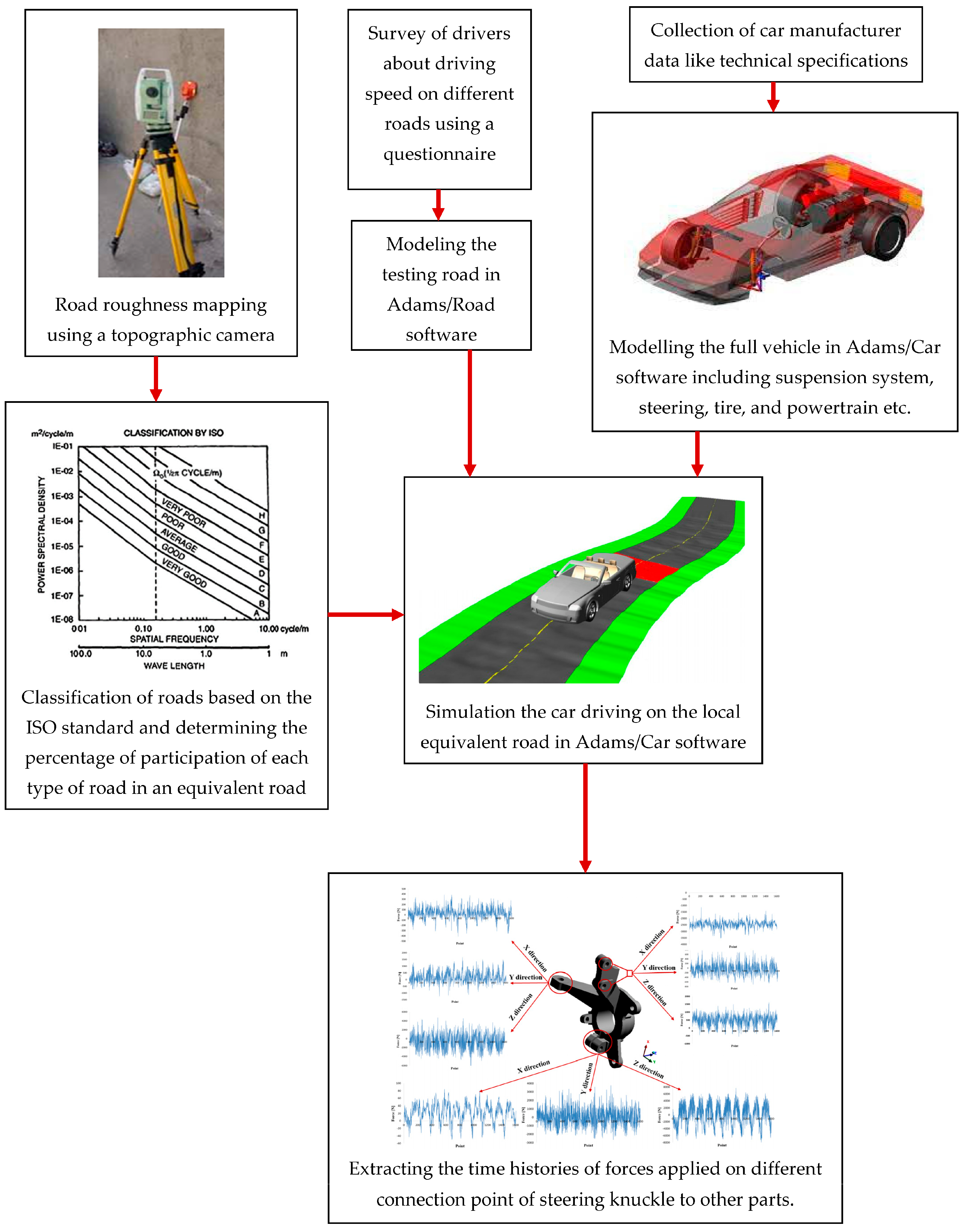
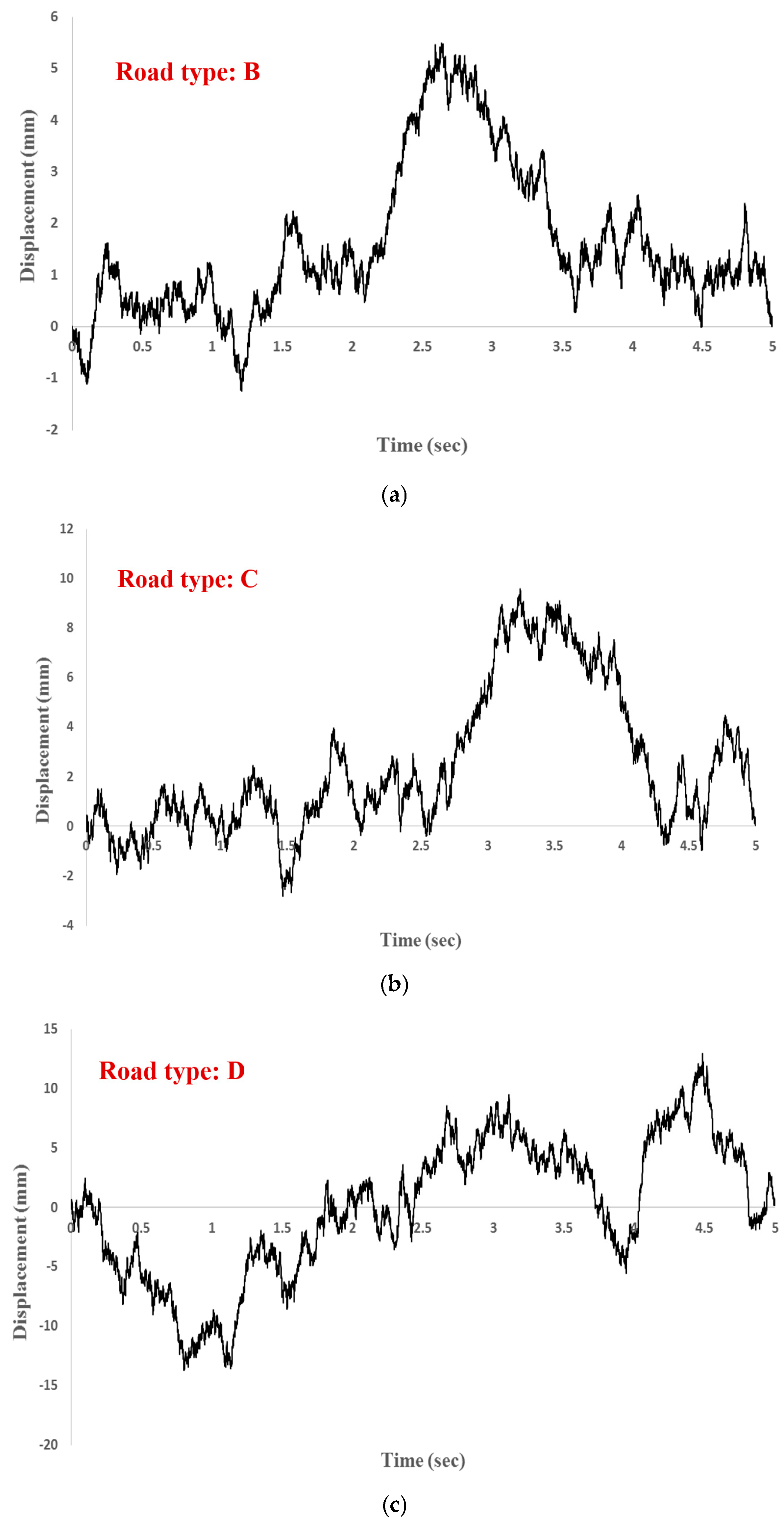
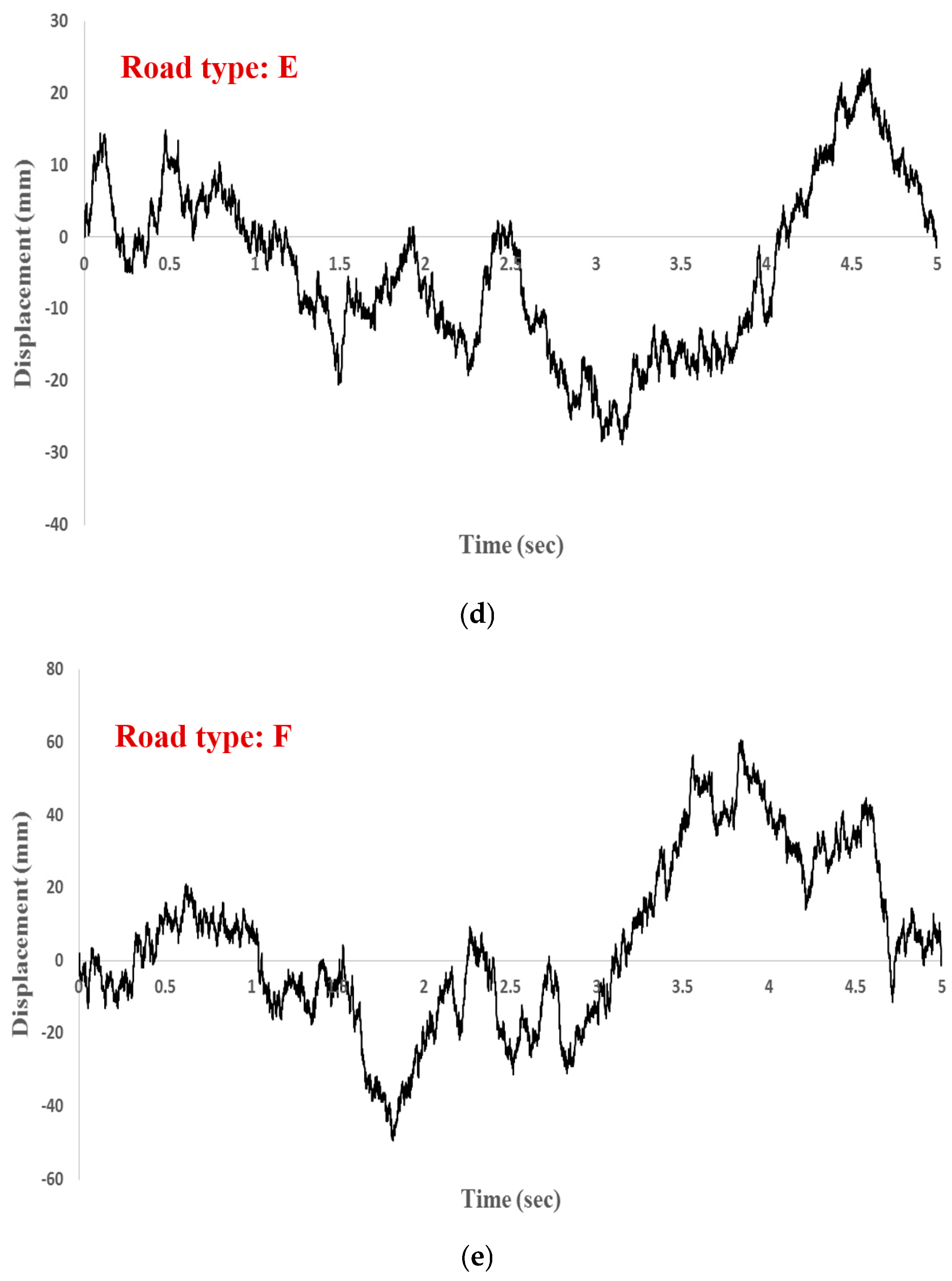
The algorithm used to extract the time histories of the forces applied to the different connection points of the steering knuckle is shown in Figure 1. At first, experimental data collection of local road roughness was carried out using a topographic camera of the Leica FlexLine TS02 model with precision of 7 s and 2 picometers for angular and longitudinal measurement, respectively [33]. Then, the local roads were classified based on the ISO standard [34,35]. Figure 2 depicts the profiles of different roads according to the roughness classification stated in the ISO standard and the measured data. Furthermore, data on the speed of movement on each of the roads was extracted according to the behavior of the drivers, which is the average result of the 2000 surveyed for each of the road categories. Table 1 reports the results of processing data collected for two Iranian cities.
To simulate a full-vehicle model consists of several main parts (i.e., the front and rear suspension systems, steering wheel, and tires); principal coordinates were defined in the middle of the front axle, so that the x-axis refers to the car’s longitudinal direction and the z-axis indicates the height. Therefore, the left and right sides of the vehicle differ only in the y-direction. The different subsystems were modeled in detail, and other settings are as follows:
- Front Suspension System (FSS)
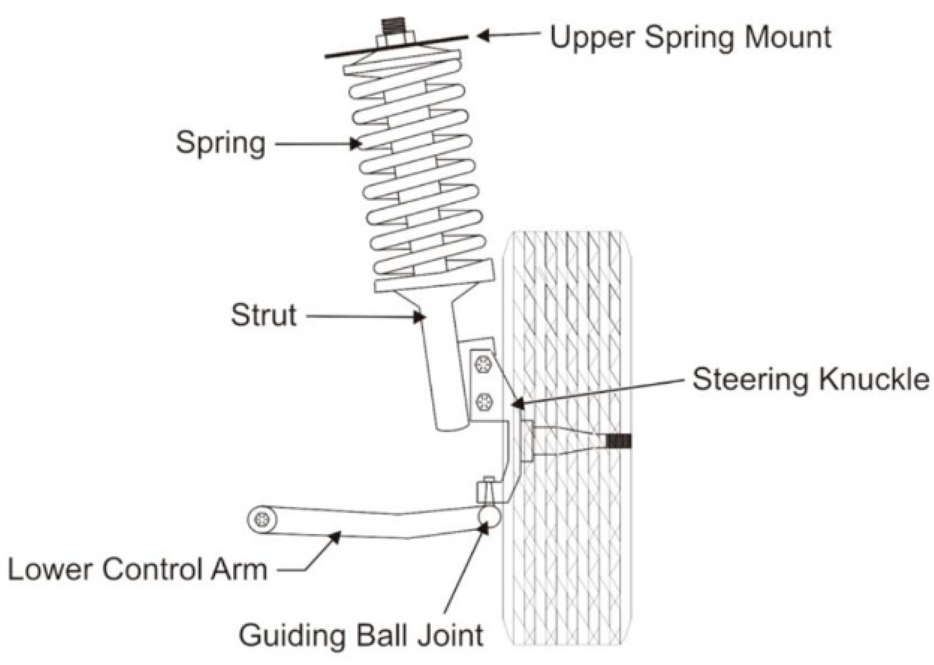
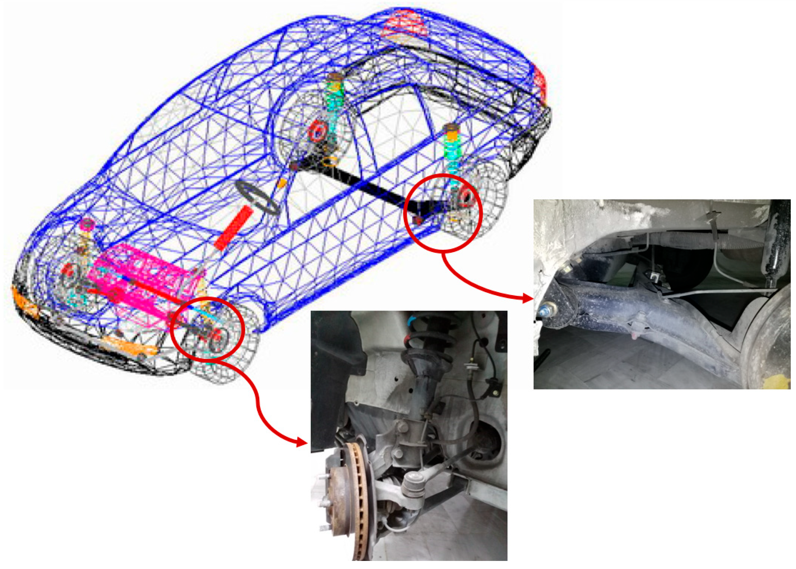
A MacPherson suspension system (Figure 3) was modeled as the FSS. This system consists of several components including a spindle, wheel center, tie rod, spring, etc. The hard points of these components are presented in Table 2.
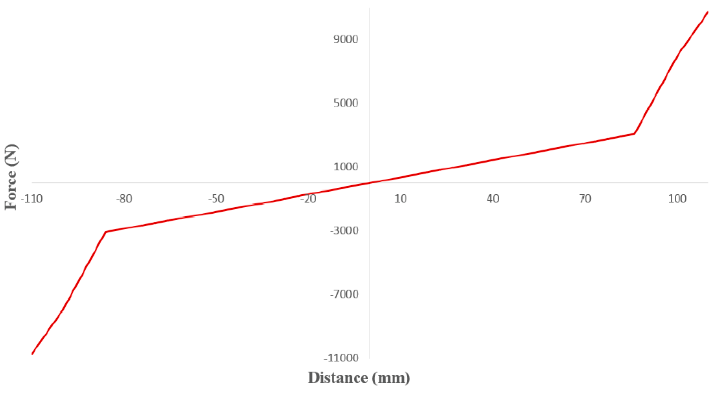
The front spring stiffness was considered to have a non-linear behavior, as shown in Figure 4. In addition, damper coefficients for the right and left sides were considered as 3105 and 1368 N.s/m, respectively [30].
- Steering Wheel System (SWS)
A rack and pinion steering system was modeled based on the hard points listed in Table 3.
- Rear Suspension System (RSS)
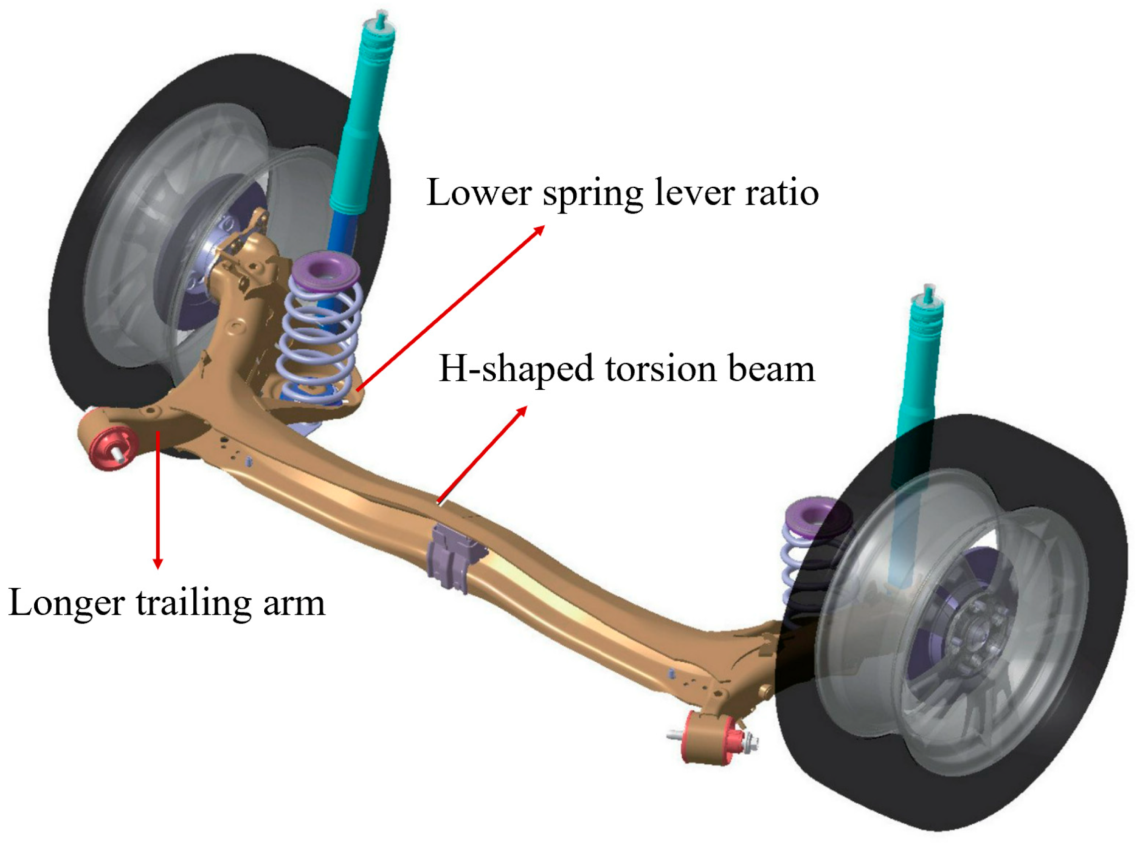
A twist beam was modeled as the RSS. Figure 5 presents a schematic of this type of suspension system. Moreover, the material properties of this subsystem are given in Table 4. The hard points of the rear suspension system in the studied vehicle are presented in Table 5.
- Tire
The tires were modeled as 175/70/R13 for the present research. In this regard, physical properties, and static as well as dynamic parameters of the tires are given in Table 6.
- Body
This subsystem consists of the center gravity of different components, such as the vehicle powertrain system. The weight of the vehicle and its center gravity from the front axle are reported in Table 7 and Table 8, respectively. The center of gravity (X, Y, and Z) of the engine without a passenger and fuel was considered at (818.5, 61.7, and 286 mm) [36].
The masses of some parts of the vehicle modeled in this research are presented in Table 9. Moreover, the inertia moment of the engine and powertrain is reported in Table 10.
- Other settings
In the studied vehicle, the distance between the two lateral axes is 1455 mm, and the distance between the rear and front axles is 2415 mm. Toe, camber, and caster angles were considered as −0.1, 2, and 1.95 degrees based on the recommendation of the manufacturer, respectively [36]. The locations of engine mounts and their pre-loads in the studied vehicle are listed in Table 11.
The properties of some bushes in terms of connecting different components to each other are presented in Table 12.
Mass and density were defined for different components to calculate the CM location relative to each part. Eventually, the full-vehicle model was simulated in ADAMS/CAR software, as illustrated in Figure 6.
3. Results and Discussion
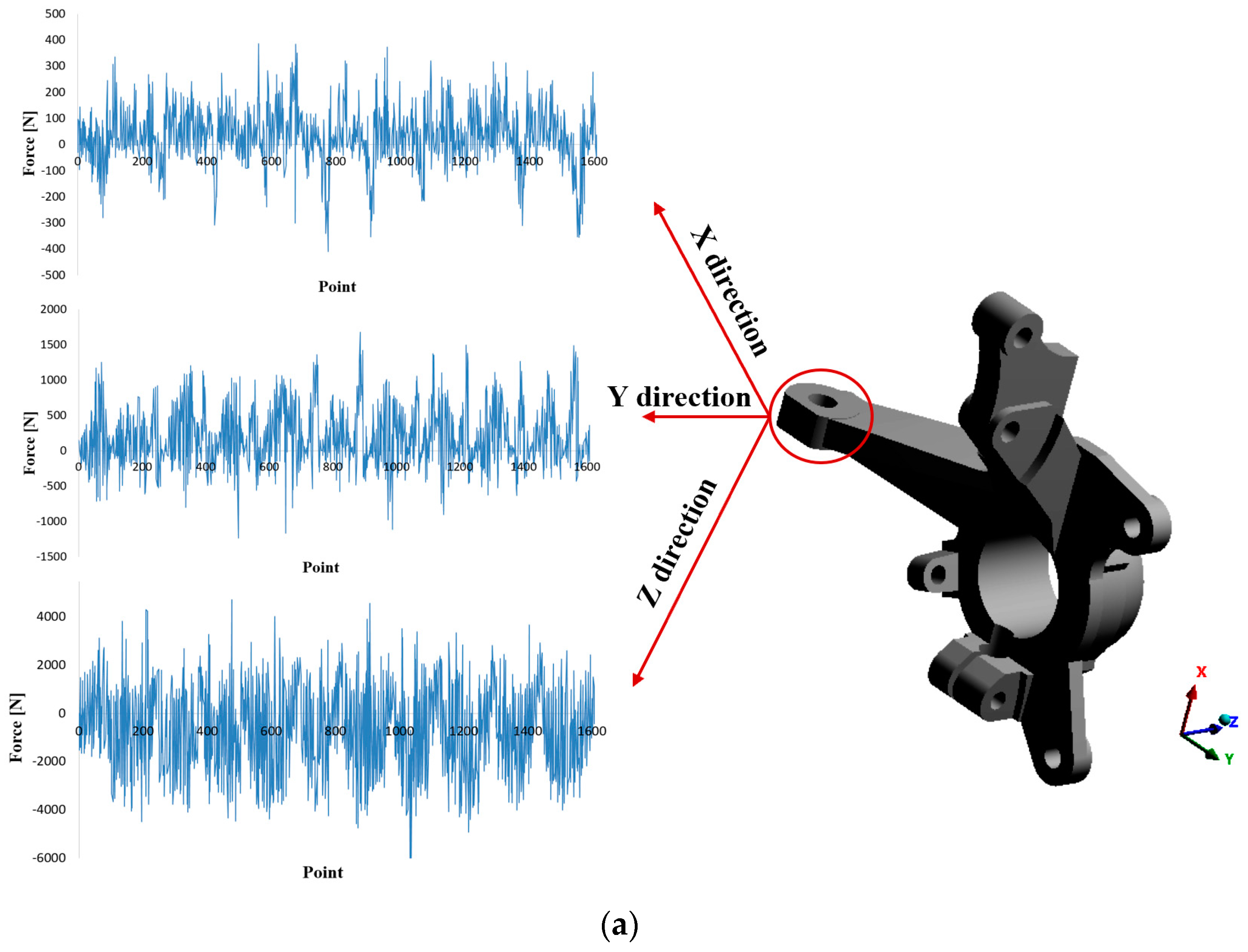
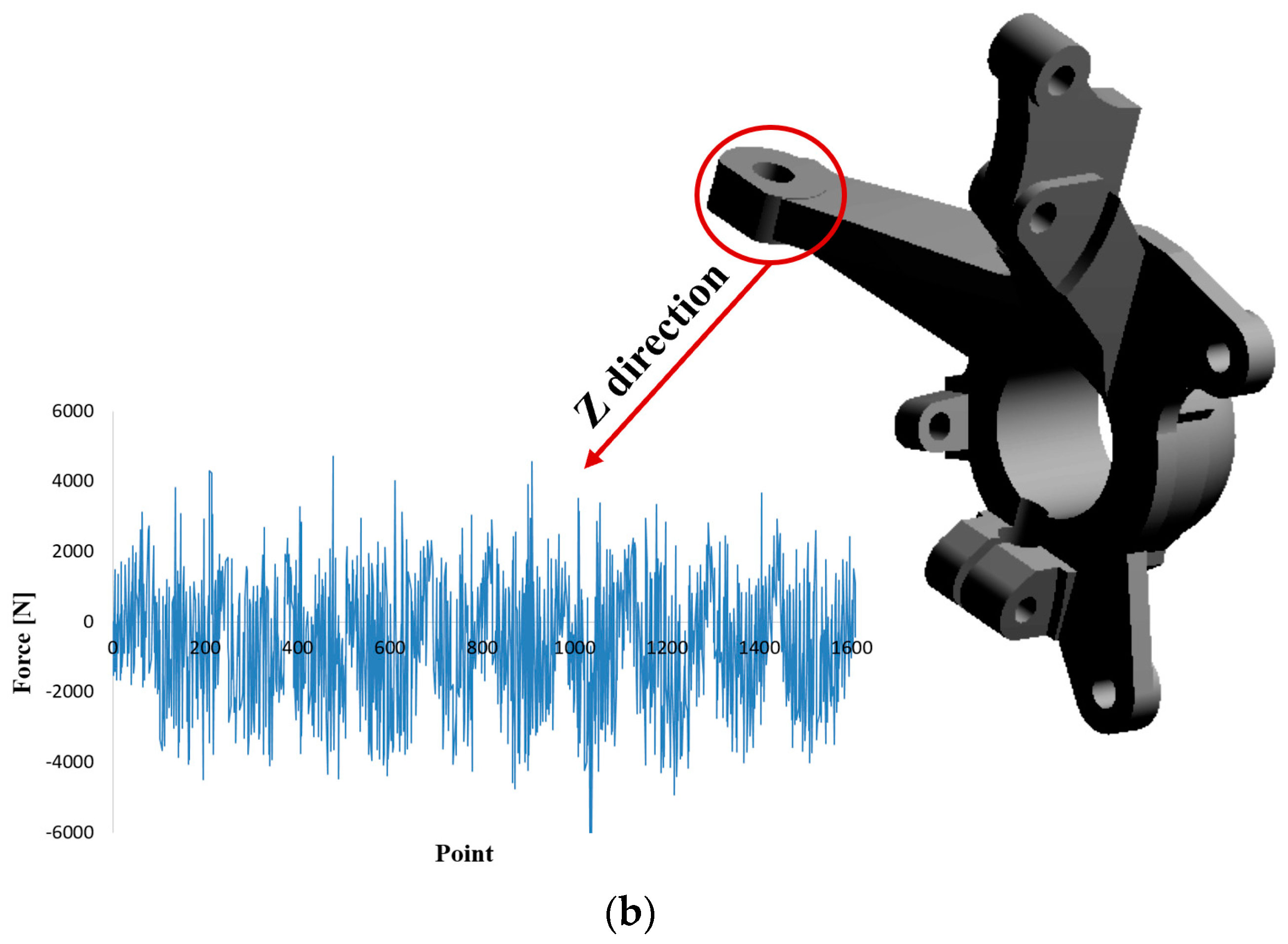
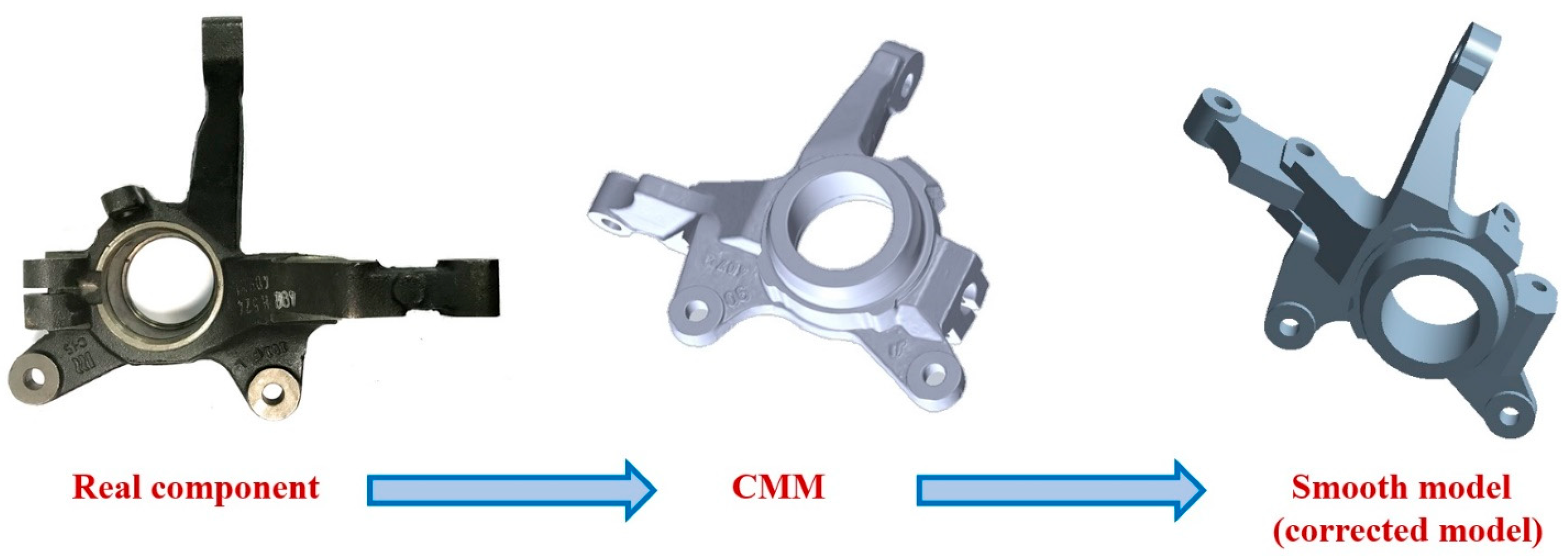
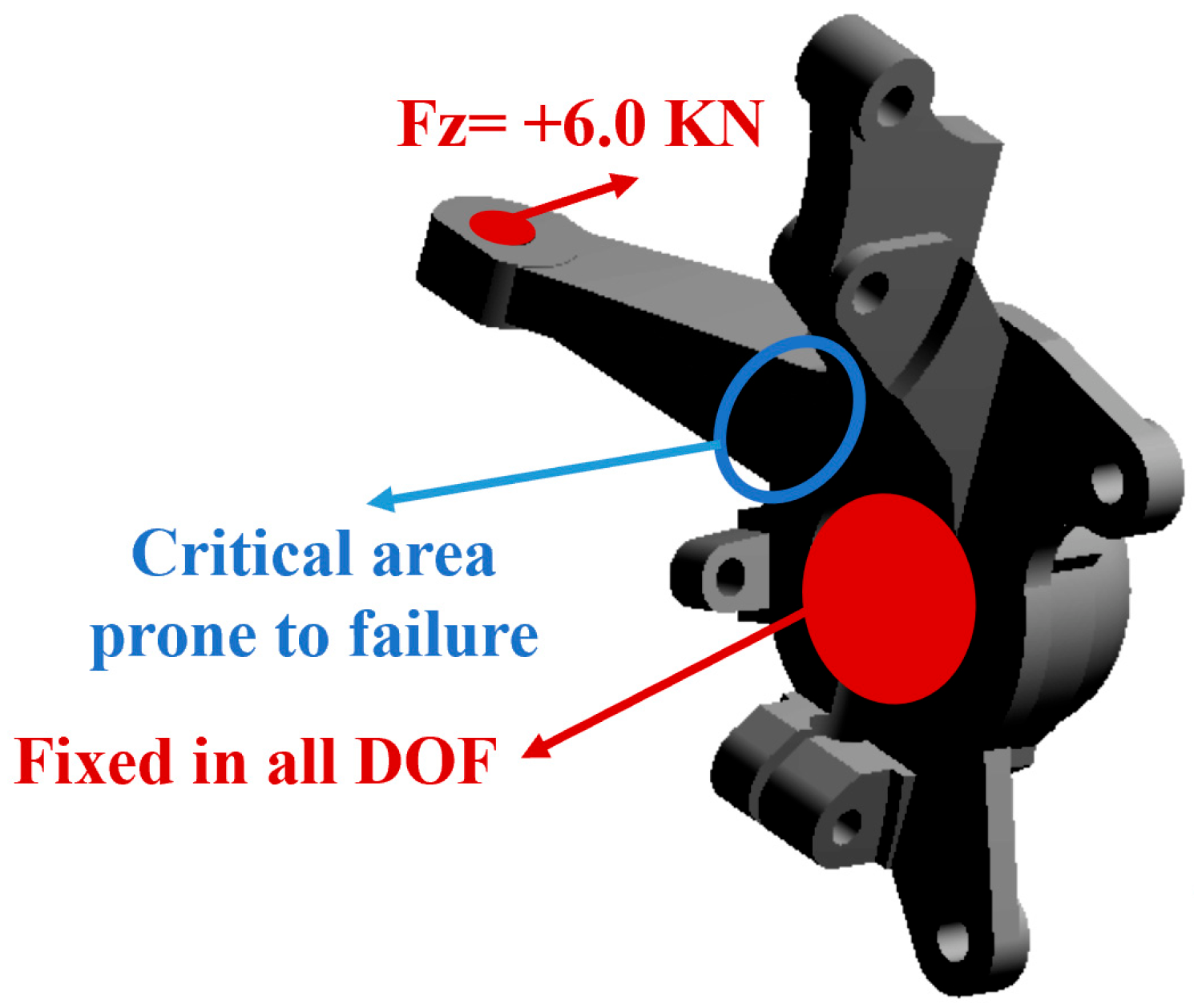
Figure 7a presents the load histories on the connection point of the steering knuckle and steering system in different directions [25]. The achievements of previous studies have shown that a rotation load in the Z-direction leads to fatigue failure of the steering knuckle (loads far less than the static strength of the material). In other words, this force has been introduced as the most destructive load under cyclic conditions caused by road excitations. Therefore, the Z-direction load history is shown in Figure 7b [25]. From this figure, the maximum and minimum static loads are equal to 6.0 and −4.5 KN, respectively. However, it is clear that this type of loading is random in nature, and it is not even possible to consider a specific trend for it. Hence, probabilistic approach techniques and loading statistical properties should be used for fatigue calculations. This topic is not in the scope of the present study and will be focused on future research, but currently the focus is on the static strength of the component. Therefore, a constant force equal to the maximum absolute value (i.e., positive 6.0 KN) was considered as the boundary condition. Furthermore, the wheel hub (i.e., the inner surface of the central hole in the steering knuckle) was fixed in all degrees of freedom. Next, stress analysis was performed, considering different materials (e.g., no reinforced aluminum and aluminum composite with different percentages of tungsten carbide). To this end, the finite element model validated by the author in previous research, including around 76,000 elements based on the results of a mesh convergence study, was used. The process of three-dimensional modeling of the steering knuckle geometry based on the appearance of the real component is shown in Figure 8. Figure 9 presents the initial and boundary conditions. Furthermore, the mechanical properties of different materials used in the present research are given in Table 13.
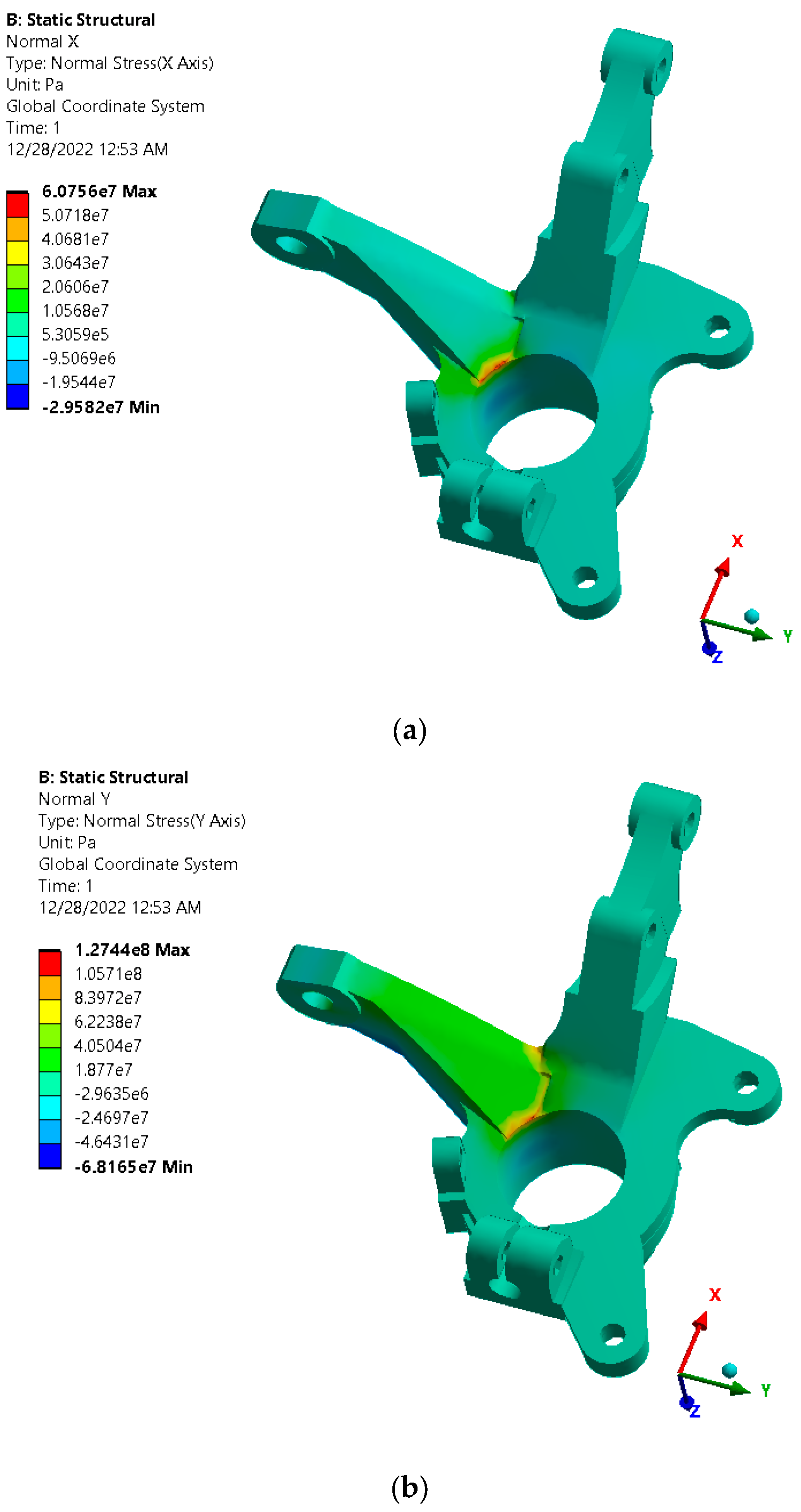
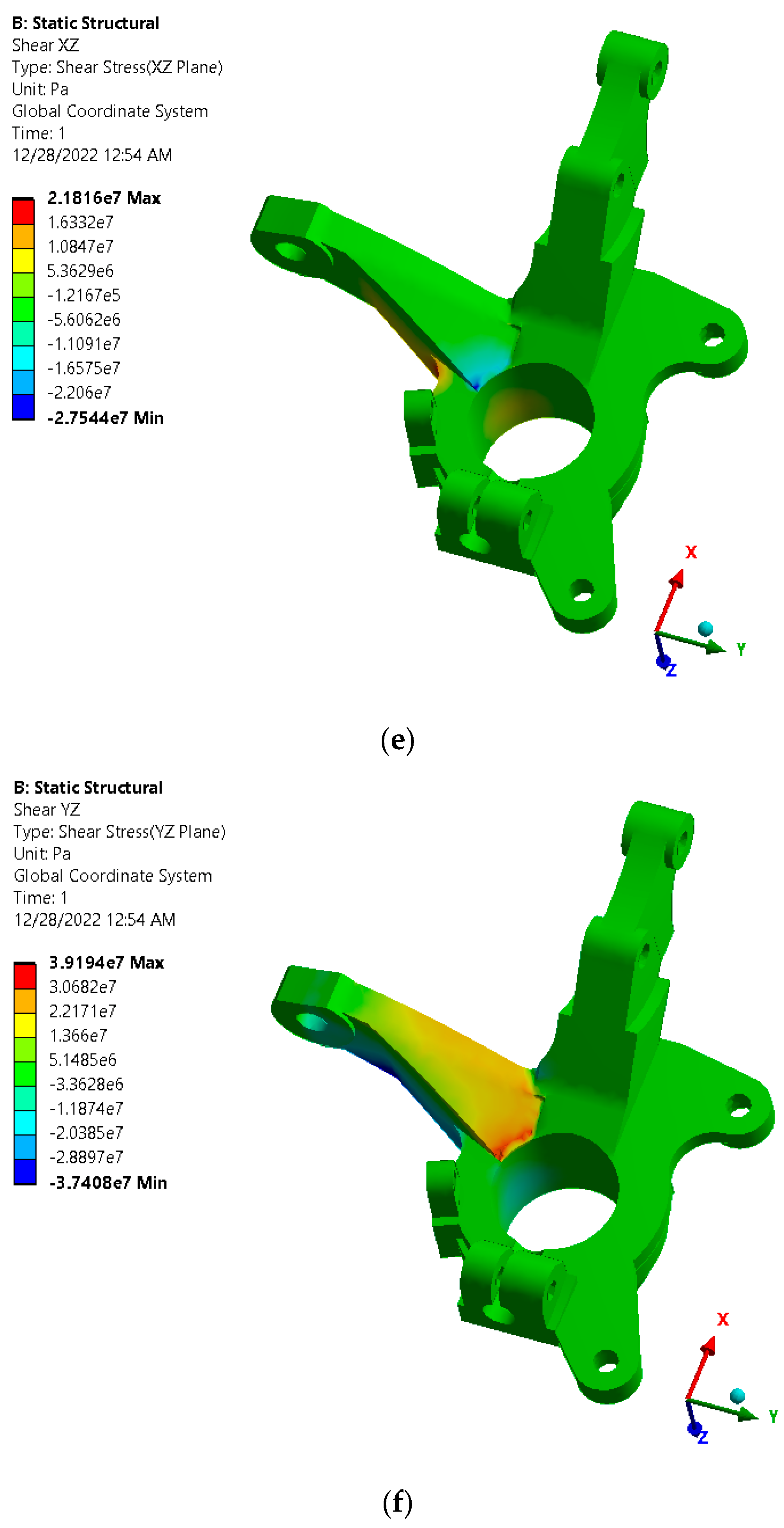
From Figure 9, the arm connecting the knuckle to the steering rod acts like a cantilever beam and faces outwards under a bending load; thus, the critical zone prone to failure is indicated. However, due to the complex geometry of the root of the steering rod, a 3D stress field is created in it, and all its components, including normal and shear stresses, must be considered. In this regard, the contours of stress components in the steering knuckle made of non-reinforced aluminum alloy are illustrated in Figure 10.
To calculate the reliability factor in the composite steering knuckle, the maximum principal stress criterion was used (Equation (1)) [37]. Furthermore, the effect of adding different percentages of tungsten carbide (i.e., 10, 12, and 15%) to strengthen the aluminum matrix composite is reported in Table 14.
From Table 14, the reliability factor of automotive steering knuckles under static load is higher in the reinforced state than in the non-reinforced state. In addition, the results showed that the reliability factor increases by adding more tungsten carbide particles to the aluminum matrix. In other words, the static strength of the automotive steering knuckle subjected to normal stress increases (e.g., the knuckle strength under static and normal load increases up to 45.56% by adding 15% carbide tungsten to the aluminum matrix). Meanwhile, the increase in tungsten carbide particles leads to a decrease in the knuckle strength due to shear stress. Moreover, the results reveal that the shear strength of the steering knuckle made of non-reinforced aluminum is much higher than the shear strength of the component made of aluminum matrix composite. Adding 10% of tungsten carbide as a reinforcement to the aluminum matrix leads to the shear strength of the knuckle being less than half. The results of previous studies in the field of knuckle failure under cyclic loads caused by road roughness and considering different maneuvers have shown that the destructive load enters the component in a shearing manner. Therefore, the use of a composite material based on an aluminum matrix and tungsten carbide as a reinforcement is not useful for this super critical component, and also weakens it. Although this result was obtained for this special component with complex geometry and the conditions stated in this article, this composite material can behave differently in standard tests and under different loadings.
4. Conclusions
This research was conducted with the aim of assessing the use of a metal matrix composite (i.e., an aluminum matrix and tungsten carbide nanoparticle reinforcement) as a lightweight material for the manufacturing of a steering knuckle. For this purpose, an attempt was made to include a case study for an Iranian passenger car, considering the local road conditions and the behavior of Iranian drivers. The most important achievements of this study are as follows:
- -
- The static reliability factor of the automotive steering knuckle is higher in the reinforced state than in the non-reinforced state.
- -
- Increasing the percentage of tungsten carbide nanoparticles as a reinforcement to the aluminum matrix leads to an increase in the static strength of the automotive steering knuckle under normal stresses and it can be predicted that its fatigue behavior will also increase under axial loading.
- -
- Steering knuckle strength under static and normal load increases up to 45.56% by adding 15% carbide tungsten to the aluminum matrix.
- -
- The strength of the automotive steering knuckle decreases under shear stress by increasing the percentage of tungsten carbide nanoparticles to the aluminum matrix.
- -
- Adding 10% of tungsten carbide nanoparticles as a reinforcement to the aluminum matrix leads to the shear strength of the knuckle being less than half.
- -
- The results showed that the use of this metal matrix composite is not suitable for this super critical component, based on the conditions considered in the present case study.
Funding
This research received no external funding.
Data Availability Statement
The data that support the findings of this study are available from the corresponding author upon reasonable request.
Acknowledgments
This paper has been supported by the RUDN University Strategic Academic Leadership Program.
Conflicts of Interest
The author declares no conflict of interest.
References
- Pahlavani, M.; Marzbanrad, J. Energy absorption study of warm-rolled dual-phase LZ71 magnesium alloy hollow tube using ANN. Automot. Sci. Eng. 2021, 11, 3514–3533. [Google Scholar] [CrossRef]
- Kulekci, M.K. Magnesium and its alloys applications in automotive industry. Int. J. Adv. Manuf. Technol. 2008, 39, 851–865. [Google Scholar] [CrossRef]
- Khademian, N.; Peimaei, Y. Magnesium alloys and applications in automotive industry. In Proceedings of the 5th International Conference on Science and Development of Nanotechnology, Tbilisi, Georgia, August 2021. [Google Scholar]
- Vinodh, S. Parametric optimization of fused deposition modelling process using Grey based Taguchi and TOPSIS methods for an automotive component. Rapid Prototyp. J. 2020, 27, 155–175. [Google Scholar] [CrossRef]
- Reddy, K.S.N.; Maranan, V.; Simpson, T.W.; Palmer, T.; Dickman, C.J. Application of topology optimization and design for additive manufacturing guidelines on an automotive component. In Proceedings of the International Design Engineering Technical Conferences and Computers and Information in Engineering Conference, Charlotte, NC, USA, 21–24 August 2016; American Society of Mechanical Engineers: New York, NY, USA, 2016; Volume 50107, p. V02AT03A030. [Google Scholar] [CrossRef]
- Kim, G.W.; Park, Y.I.; Park, K. Topology Optimization and Additive Manufacturing of Automotive Component by Coupling Kinetic and Structural Analyses. Int. J. Automot. Technol. 2020, 21, 1455–1463. [Google Scholar] [CrossRef]
- Abdi, M.; Ashcroft, I.; Wildman, R.D. Design optimization for an additively manufactured automotive component. Int. J. Powertrains 2018, 7, 142–161. [Google Scholar] [CrossRef]
- Zoroufi, M.; Fatemi, A. Experimental durability assessment and life prediction of vehicle suspension components: A case study of steering knuckles. Proc. Inst. Mech. Eng. Part D J. Automob. Eng. 2006, 220, 1565–1579. [Google Scholar] [CrossRef]
- Fatemi, A.; Zoroufi, M. Fatigue Performance Evaluation of Forged versus Competing Manufacturing Process Technologies: A Comparative Analytical and Experimental Study; American Iron and Steel Institute: Toledo, Spain, 2004. [Google Scholar]
- Reza Kashyzadeh, K.; Ostad-Ahmad-Ghorabi, M.J.; Arghavan, A. Fatigue life prediction of package of suspension automotive under random vibration based on road roughness. Med. J. Model. Simul 2015, 4, 050. Available online: http://193.194.80.11/jspui/bitstream/123456789/1026/1/MJMS%2004%20%20037%E2%80%93050.pdf (accessed on 16 November 2022).
- Fahmi, A.T.W.K.; Kashyzadeh, K.R.; Ghorbani, S. A comprehensive review on mechanical failures cause vibration in the gas turbine of combined cycle power plants. Eng. Fail. Anal. 2022, 134, 106094. [Google Scholar] [CrossRef]
- Azadi, S.; Azadi, M.; Zahedi, F. NVH analysis and improvement of a vehicle body structure using DOE method. J. Mech. Sci. Technol. 2009, 23, 2980–2989. [Google Scholar] [CrossRef]
- Reza Kashyzadeh, K.; Farrahi, G.H.; Shariyat, M.; Ahmadian, M.T. Experimental and finite element studies on free vibration of automotive steering knuckle. Int. J. Eng. 2017, 30, 1776–1783. [Google Scholar] [CrossRef]
- Madhusudhanan, S.; Rajendran, I.; Prabu, K. Static analysis of automotive steering knuckle. Appl. Mech. Mater. 2014, 592, 1155–1159. [Google Scholar] [CrossRef]
- Saputro, B.A.; Ubaidillah; Triono, D.A.; Pratama, D.R.; Cahyono, S.I.; Imaduddin, F. Static load simulation of steering knuckle for a formula student race car. In AIP Conference Proceedings; AIP Publishing: Melville, NY, USA, 2018; Volume 1931, p. 030049. [Google Scholar] [CrossRef]
- Wang, H.W.; Yu, L.L. Strength analysis of steering knuckle arm on veyron car. Adv. Mater. Res. 2012, 562, 627–630. [Google Scholar] [CrossRef]
- Rajeshkumar, L.; Bhuvaneswari, V.; Pradeepraj, B.; Palanivel, C. Design and Optimization of Static Characteristics for a Steering System in an ATV. IOP Conf. Ser. Mater. Sci. Eng. 2020, 954, 012009. [Google Scholar] [CrossRef]
- Zhou, Y.; Li, H. Study on failure assessment and experimental validation of automotive steering knuckle in McPherson front suspension system. Proc. Inst. Mech. Eng. Part D J. Automob. Eng. 2022, 09544070221121833. [Google Scholar] [CrossRef]
- Böhm, R.; Hornig, A.; Weber, T.; Grüber, B.; Gude, M. Experimental and Numerical Impact Analysis of Automotive Bumper Brackets Made of 2D Triaxially Braided CFRP Composites. Materials 2020, 13, 3554. [Google Scholar] [CrossRef]
- Davoodi, M.M.; Sapuan, S.M.; Ahmad, D.; Ali, A.; Khalina, A.; Jonoobi, M. Mechanical properties of hybrid kenaf/glass reinforced epoxy composite for passenger car bumper beam. Mater. Des. 2010, 31, 4927–4932. [Google Scholar] [CrossRef]
- Fitri, M.; Mahzan, S.; Anggara, F. The Mechanical Properties Requirement for Polymer Composite Automotive Parts—A Review. Inst. Res. Innov. Ind. Syst. 2020, 1, 125–133. [Google Scholar] [CrossRef]
- Magurno, A. Vegetable fibres in automotive interior components. Angew. Makromol. Chem. 1999, 272, 99–107. [Google Scholar] [CrossRef]
- Farrahi, G.H.; Ahmadi, A.; Kasyzadeh, K.R. Simulation of vehicle body spot weld failures due to fatigue by considering road roughness and vehicle velocity. Simul. Model. Pract. Theory 2020, 105, 102168. [Google Scholar] [CrossRef]
- Kashyzadeh, K.R. A new algorithm for fatigue life assessment of automotive safety components based on the probabilistic approach: The case of the steering knuckle. Eng. Sci. Technol. Int. J. 2020, 23, 392–404. [Google Scholar] [CrossRef]
- Reza Kashyzadeh, K. Effects of axial and multiaxial variable amplitude loading conditions on the fatigue life assessment of automotive steering knuckle. J. Fail. Anal. Prev. 2020, 20, 455–463. [Google Scholar] [CrossRef]
- Vijayarangan, S.; Rajamanickam, N.; Sivananth, V. Evaluation of metal matrix composite to replace spheroidal graphite iron for a critical component, steering knuckle. Mater. Des. 2013, 43, 532–541. [Google Scholar] [CrossRef]
- Sivananth, V.; Vijayarangan, S. Fatigue life analysis and optimization of a passenger car steering knuckle under operating conditions. Int. J. Automot. Mech. Eng. 2015, 11, 2417–2429. [Google Scholar] [CrossRef]
- Das, P.; Bhuniya, B.; Samanta, S.K.; Dutta, P. Studies on die filling of A356 Al alloy and development of a steering knuckle component using rheo pressure die casting system. J. Mater. Process. Technol. 2019, 271, 293–311. [Google Scholar] [CrossRef]
- Jeon, G.T.; Kim, K.Y.; Moon, J.H.; Lee, C.; Kim, W.J.; Kim, S.J. Effect of Al 6061 alloy compositions on mechanical properties of the automotive steering knuckle made by novel casting process. Metals 2018, 8, 857. [Google Scholar] [CrossRef]
- Reza Kashyzadeh, K.; Farrahi, G.H.; Shariyat, M.; Ahmadian, M.T. The Role of Wheel Alignment Over the Fatigue Damage Accumulation in Vehicle Steering Knuckle. J. Stress Anal. 2018, 3, 21–33. [Google Scholar] [CrossRef]
- Kashyzadeh, K.R.; Farrahi, G.H.; Shariyat, M.; Ahmadian, M.T. Experimental accuracy assessment of various high-cycle fatigue criteria for a critical component with a complicated geometry and multi-input random non-proportional 3D stress components. Eng. Fail. Anal. 2018, 90, 534–553. [Google Scholar] [CrossRef]
- Marzbanrad, J.; Hoseinpour, A. Structural optimization of macpherson control arm under fatigue loading. Teh. Vjesn. Tech. Gaz. 2017, 24, 917–924. [Google Scholar] [CrossRef]
- Reza-Kashyzadeh, K.; Ostad-Ahmad-Ghorabi, M.J.; Arghavan, A. Study effects of vehicle velocity on a road surface roughness simulation. Appl. Mech. Mater. 2013, 372, 650–656. [Google Scholar] [CrossRef]
- Sun, L. Optimum design of “road-friendly” vehicle suspension systems subjected to rough pavement surfaces. Appl. Math. Model. 2022, 26, 635–652. [Google Scholar] [CrossRef]
- González, A.; O’brien, E.J.; Li, Y.Y.; Cashell, K. The use of vehicle acceleration measurements to estimate road roughness. Veh. Syst. Dyn. 2008, 46, 483–499. [Google Scholar] [CrossRef]
- Reza Kashyzadeh, K. Fatigue Life Estimation of Automotive Steering Knuckle in Various Maneuvers under Constant and Variable Amplitude Loadings. Ph.D. Thesis, Sharif University of Technology, Tehran, Iran, 2018. [Google Scholar]
- Nouri, M.; Ashenai-Ghasemi, F.; Rahimi-Sherbaf, G.; Kashyzadeh, K.R. Experimental and numerical study of the static performance of a hoop-wrapped CNG composite cylinder considering its variable wall thickness and polymer liner. Mech. Compos. Mater. 2020, 56, 339–352. [Google Scholar] [CrossRef]
Figure 1.
The used algorithm to extract the time histories of the forces applied to different connection points of the steering knuckle.
Figure 1.
The used algorithm to extract the time histories of the forces applied to different connection points of the steering knuckle.

Figure 2.
Road profiles extracted based on the data recorded by the topographic camera and employing standard classification, including (a) road type B—highway out of town, (b) road type C—urban highway, (c) road type D—urban asphalt, (d) road type E—soil road, and (e) road type F—flagstone.
Figure 2.
Road profiles extracted based on the data recorded by the topographic camera and employing standard classification, including (a) road type B—highway out of town, (b) road type C—urban highway, (c) road type D—urban asphalt, (d) road type E—soil road, and (e) road type F—flagstone.


Figure 3.
Schematic of the MacPherson suspension assembly.

Figure 4.
Diagram of spring behavior in the suspension system of the studied vehicle [30].
Figure 4.
Diagram of spring behavior in the suspension system of the studied vehicle [30].

Figure 5.
Schematic of the twist beam for the rear suspension system.

Figure 6.
Full-vehicle model in ADAMS/CAR software [30].
Figure 6.
Full-vehicle model in ADAMS/CAR software [30].

Figure 7.
Various load histories extracted from MBD simulation of full-vehicle movement on a local equivalent road [25]. (a) Load histories on the connection point of the steering knuckle and steering system in different directions. (b) Load histories on the connection point of the steering knuckle and steering system in the Z-direction.


Figure 8.
The 3D modeling process of a knuckle based on the appearance characteristics of the geometry.
Figure 8.
The 3D modeling process of a knuckle based on the appearance characteristics of the geometry.

Figure 9.
Boundary and initial conditions considered in the current research.

Figure 10.
Contours of stress components in the steering knuckle made of non-reinforced aluminum alloy, including (a) normal stress in the X-direction, (b) normal stress in the Y-direction, (c) normal stress in the Z-direction, (d) shear stress in the XY-plane, (e) shear stress in the XZ-plane, and (f) shear stress in the YZ-plane.


Table 1.
Results of processing data collected for different Iranian cities.
| City | Road | Urban Asphalt | Urban Highway | Highway Out of Town | Soil Road | Flagstone |
|---|---|---|---|---|---|---|
| Tehran | Participation (%) | 31.5 | 34.75 | 27.25 | 5.25 | 1.25 |
| speed (km/h) | 43.75 | 70.75 | 91 | 12.5 | 3 | |
| Qom | Participation (%) | 9.73 | 46.05 | 33.42 | 8.94 | 1.86 |
| speed (km/h) | 28.68 | 62.63 | 113.68 | 24.47 | 5 |
Table 2.
Hard points of the MacPherson suspension system in the studied vehicle (all dimensions are in millimeters) [36].
Table 2.
Hard points of the MacPherson suspension system in the studied vehicle (all dimensions are in millimeters) [36].
| Component | X | Y | Z |
|---|---|---|---|
| hpl_drive_shaft_inr | 0 | −200 | 225 |
| hpl_ica_front | −110 | −592.5 | 197.6 |
| hpl_ica_outer | 0 | 662.5 | 167.6 |
| hpl_ica_rear | 110 | −387.5 | 287.6 |
| hpl_spring_lower_seat | 10 | −567.5 | 672.6 |
| hpl_strut_lwr_mount | 0 | −578.5 | 377.6 |
| hpl_subframe_front | −570 | −397.5 | 257.6 |
| hpl_subframe_rear | 460 | −397.5 | 257.6 |
| hpl_tierod_inner | 470 | −192.5 | 497.6 |
| hpl_tierod_outer | 120 | −617.5 | 397.6 |
| hpl_top_mount | 10 | −557.5 | 862.6 |
| hpl_wheel_center | 0 | 730 | 287.6 |
Table 3.
Hard points of a rack and pinion steering wheel system in the studied vehicle (all dimensions are in millimeters) [36].
Table 3.
Hard points of a rack and pinion steering wheel system in the studied vehicle (all dimensions are in millimeters) [36].
| Component | X | Y | Z |
|---|---|---|---|
| hpl_rack_house_mount | 120 | −400 | 397.6 |
| hpl_tierod_inner | 120 | −425 | 397.6 |
| hps_intermediate_shaft rearward | 860 | −277.5 | 887.6 |
| hps_intermediate_shaft forward | 670 | −277.5 | 857.6 |
| hps_pinion_pivot | 120 | −300 | 397.6 |
| hps_steering_wheel_center | 870 | −277.5 | 917.6 |
Table 4.
Material properties of the twist beam in the studied vehicle [36].
Table 4.
Material properties of the twist beam in the studied vehicle [36].
| Elastic Modulus | Density | Yield Stress | Ultimate Stress |
|---|---|---|---|
| 210 GPa | 7860 kg/m3 | 304 MPa | 441 MPa |
Table 5.
Hard points of the rear suspension system in the studied vehicle (all dimensions are in millimeters) [36].
Table 5.
Hard points of the rear suspension system in the studied vehicle (all dimensions are in millimeters) [36].
| Component | X | Y | Z |
|---|---|---|---|
| Rear wheel center | 2415 | 727.5 | 0 |
| Lower mount | 2415 | 577.5 | −100 |
| Upper mount | 2445 | 427.5 | 640 |
| First connecting | 2415 | 727.5 | 0 |
| Second connecting | 2205 | 552.5 | 20 |
| Third connecting | 2065 | 552.5 | 40 |
Table 6.
All data of tire parameters [36].
Table 6.
All data of tire parameters [36].
| Parameters | 175/70/R13 | |
|---|---|---|
| Static Input Data | Tire section width in mm | 175 |
| Aspect ratio in % | 70 | |
| Rim diameter in inches | 13 | |
| Rim width in inches (manufacture’s measuring rim) | 5 | |
| Tire load index number | 82 | |
| Tire speed index letter | H | |
| Static Output Data | Tire outer diameter in mm (air pressure and no load) | 576 |
| Tire section width in mm (air pressure and no load) | 175 | |
| Tire section height in mm (air pressure and no load) | 123 | |
| Static load radius in mm (maximum load and air pressure) | 261 | |
| Tire rolling radius in mm at 60 km/h (load and air pressure) | 1757.4 | |
| Dynamic rolling radius in mm at 60 km/h (load and air pressure) | 280 | |
| Tire stiffness rate in kg/mm (load and air pressure) | 17.2 | |
| Tire air volume in liters (load and air pressure) | 22.9 | |
| Dynamic Input Data | Vehicle corner weight in kg (right/left or front/rear) | 405 |
| Air pressure in bar | 2.5 | |
| Vehicle speed in km/h | 60 | |
| Dynamic Output Data | Vehicle tire lower section width in mm (vehicle load, speed, and air pressure) | 219 |
| Vehicle tire lower section height in mm (vehicle load, speed, and air pressure) | 99.5 | |
| Vehicle tire deflection in mm (vehicle load, speed, and air pressure) | 23.5 | |
| Vehicle tire rolling circumference in mm (vehicle load, speed, and air pressure) | 1662.7 | |
| Vehicle dynamic rolling radius in mm if speed = 0 (vehicle load, speed, and air pressure) | 264.6 | |
| Vehicle tire stiffness rate in kg/mm (speed and air pressure) | 17.3 | |
| Contact patch width in mm (vehicle load, speed, and air pressure) | 133 | |
| Contact patch length in mm (vehicle load, speed, and air pressure) | 140 | |
| Contact patch are in square centimeter | 186.9 | |
| Speedometer reading in Km/h | 60 | |
| Tire suspension comfort value | 10 | |
Table 7.
Different types of full-vehicle mass [36].
Table 7.
Different types of full-vehicle mass [36].
| Type | Total | % Front | % Rear |
|---|---|---|---|
| Kerb (empty plus fuel) | 1013 | 58.3 | 41.7 |
| Design | 1308 | 51.4 | 48.6 |
| GVW (20 litr fuel + 4 × 75 kg) | 1383 | 49.2 | 50.8 |
Table 8.
Center of gravity of the vehicle from the front axle (mm) [36].
Table 8.
Center of gravity of the vehicle from the front axle (mm) [36].
| X | Y | Z | |
|---|---|---|---|
| Kerb without Occupant | 1180 | 0 | 550 |
| Design | 1190 | 0 | 500 |
Table 9.
Masses of some components of the vehicle modeled in the present research [36].
Table 9.
Masses of some components of the vehicle modeled in the present research [36].
| Component | Mass (kg) |
|---|---|
| Front door | 20.22 |
| Rear door | 13.95 |
| Front seat | 12.5 |
| Rear seat | 19.6 |
| Dash | 15 |
| Fuel tank | 45 |
| Battery | 13 |
| Engine | 144.5 |
| Powertrain | 157.2 |
Table 10.
Inertia moment of the engine and powertrain in the studied vehicle [36].
Table 10.
Inertia moment of the engine and powertrain in the studied vehicle [36].
| Component | Inertia Moment | Value |
|---|---|---|
| Engine | Ixx | 4.072 × 10⁶ |
| Iyy | 8.634 × 10⁶ | |
| Izz | 7.294 × 10⁶ | |
| Ixy | 0.123 × 10⁶ | |
| Iyz | 0.249 × 10⁶ | |
| Ixz | 1.102 × 10⁶ | |
| Powertrain | Ixx | 11.98 × 10⁶ |
| Iyy | 5.868 × 10⁶ | |
| Izz | 9.972 × 10⁶ | |
| Ixy | 0 | |
| Iyz | 0 | |
| Ixz | 0 |
Table 11.
Locations and pre-loads of engine mounts in the studied vehicle (all dimensions are in millimeters) [36].
Table 11.
Locations and pre-loads of engine mounts in the studied vehicle (all dimensions are in millimeters) [36].
| Mount | Location | Pre-Load | ||
|---|---|---|---|---|
| X | Y | Z | ||
| EM1 | 1136.7 | −165.2 | 41 | 423 N |
| EM2 | 607.8 | −140.3 | 102.7 | 590 N |
| EM3 | 799 | 480.5 | 450.8 | 533 N |
Table 12.
Properties of bushes and stiffness of components [36].
Table 12.
Properties of bushes and stiffness of components [36].
| Component | Direction | Bush (N/mm) | Stiffness (N/m) |
|---|---|---|---|
| Torsion beam | X | 350 | 51,653 |
| Y | 2000 | 12,850 | |
| Z | 3000 | 20,563 | |
| Front control arm | Bending-road input | 1700 | 9217 |
| Axial | 45,000 | 887,190 | |
| Anti-roll bar bracket | Mount X | 1136 | 178,827 |
| Mount Y | 84 | 40,634 |
Table 13.
Mechanical properties of different group of materials used in the present research.
| Properties [Unit] | Density [kg/m3] | Elastic Modulus [GPa] | Poisson’s Ratio | Yield Stress [MPa] | Tensile Ultimate Stress [MPa] |
|---|---|---|---|---|---|
| Material | |||||
| Non-reinforced Al alloy [26] | 2700 | 73 | 0.33 | 187 | 254 |
| MMC-Al-10%-TiC [26] | 2770 | 79 | 0.33 | 201 | 281 |
| MMC-Al-12%-TiC [13] | 2800 | 84 | 0.33 | 213 | 289 |
| MMC-Al-15%-TiC [13] | 2850 | 87 | 0.33 | 265 | 323 |
Table 14.
The calculation of reliability factor for steering knuckles made of different materials under static load.
Table 14.
The calculation of reliability factor for steering knuckles made of different materials under static load.
| Material | Non-Reinforced Al Alloy | Composite | ||
|---|---|---|---|---|
| TiC 10% | TiC 12% | TiC 15% | ||
| Reliability factor—normal stress (%) | 1.69 | 2.14 | 2.20 | 2.46 |
| Reliability factor—shear stress (%) | 2.16 | 1.03 | 0.87 | 0.82 |
Disclaimer/Publisher’s Note: The statements, opinions and data contained in all publications are solely those of the individual author(s) and contributor(s) and not of MDPI and/or the editor(s). MDPI and/or the editor(s) disclaim responsibility for any injury to people or property resulting from any ideas, methods, instructions or products referred to in the content. |
© 2023 by the author. Licensee MDPI, Basel, Switzerland. This article is an open access article distributed under the terms and conditions of the Creative Commons Attribution (CC BY) license (https://creativecommons.org/licenses/by/4.0/).
Share and Cite
MDPI and ACS Style
Reza Kashyzadeh, K. Failure Strength of Automotive Steering Knuckle Made of Metal Matrix Composite. Appl. Mech. 2023, 4, 210-229. https://doi.org/10.3390/applmech4010012
AMA Style
Reza Kashyzadeh K. Failure Strength of Automotive Steering Knuckle Made of Metal Matrix Composite. Applied Mechanics. 2023; 4(1):210-229. https://doi.org/10.3390/applmech4010012
Chicago/Turabian StyleReza Kashyzadeh, Kazem. 2023. "Failure Strength of Automotive Steering Knuckle Made of Metal Matrix Composite" Applied Mechanics 4, no. 1: 210-229. https://doi.org/10.3390/applmech4010012