Structural Analysis of a Composite Passenger Seat for the Case of an Aircraft Emergency Landing

Department of Mechanical Engineering and Aeronautics, University of Patras, Patras University Campus, 26504 Patra, Greece
*
Author to whom correspondence should be addressed.
Appl. Mech. 2023, 4(1), 1-19; https://doi.org/10.3390/applmech4010001
Submission received: 27 November 2022
/
Revised: 21 December 2022
/
Accepted: 25 December 2022
/
Published: 28 December 2022
(This article belongs to the Special Issue Feature Papers in Applied Mechanics)
Abstract
:Aviation authorities require, from aircraft seat manufacturers, specific performance metrics that maximize the occupants’ chances of survival in the case of an emergency landing and allow for the safe evacuation of the aircraft cabin. Therefore, aircraft seats must comply with specific requirements with respect to their structural integrity and potential occupant injuries, which are certified through the conduction of costly, full-scale tests. To reduce certification costs, computer-aided methods such as finite element analysis can simulate and predict the responses of different seat configuration concepts and potentially save time and development costs. This work presents one of the major steps of an aircraft seat development, which is the design and study of preliminary design concepts, whose structural and biomechanical response will determine whether the concept seat model is approved for the next steps of development. More specifically, a three-occupant aircraft seat configuration is studied for crash landing load cases and is subjected to modification iterations from a baseline design to a composite one for its structural performance, its weight reduction and the reduction of forces transmitted to the passengers.
1. Introduction
The main safety-related requirements of aircraft seats emerge in the case of an aircraft emergency landing, where the transmitted loads to the passengers can be fatal, both in terms of intensity and duration time. Therefore, the energy absorbing systems play a fundamental role in the energy unleashed during the impact [1]. Moreover, in the event of a minor crash landing, the individuals who can freely evacuate the interior of the plane have a higher chance of surviving. Thus, authorities related to the flight safety, such as the Federal Aviation Administration (FAA), European Aviation Safety Agency (EASA) and Joint Aviation Authorities (JAA), have applied specific regulations concerning matters of passengers’ safety during emergency landings. Most of the research and consequent certification requirements are confined to the seating capacity of impact energy absorption, assuming a rigid behavior of the surrounding structure [1]. Furthermore, biomechanical loads that apply to the occupants and the structural integrity of the seat’s main body are of high priority in the aircraft seat’s study, since the seat is an interface between the individual and the fuselage [2].
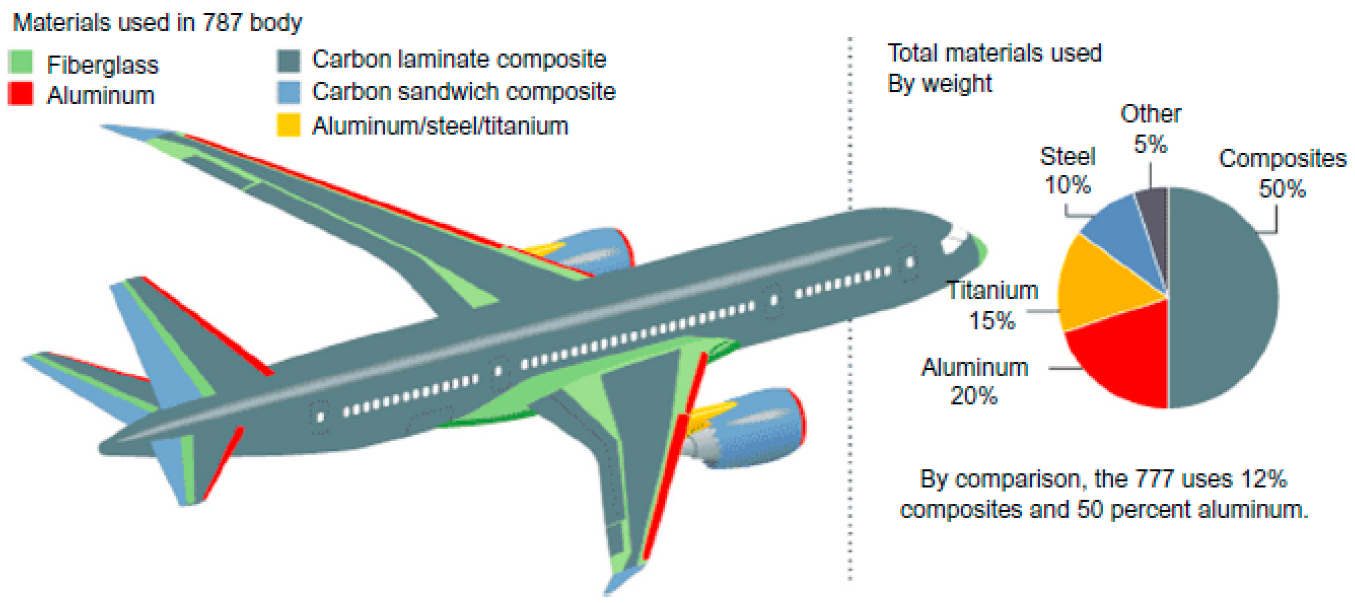
In addition to the protection of the occupants and the energy-absorbing capabilities of the seats, a second design parameter that emerges is the overall weight of the structure, which is related to the fuel consumption of the aircraft. The factor of the strength/weight ratio has always been one of the greatest concerns of the aircraft industry. The strength/weight ratio is the main reason why composite materials were used in military aviation in the 1960s and later in civil aviation, where their use was confined to the development of secondary structural components. However, during the 2000s, a great innovation in the use of composites took place with the production of two aircraft types, the Airbus A380 and the Boeing Dreamliner, which extensively used composites in their primary structures [3].
As shown in Figure 1, contemporary aircraft structures have their major components constructed of composite materials, while at the same time, a procedure of innovated lightweight seats development is also observed, along with their deployment by the airlines. Thus, the study of composite materials in aircraft seat structures is of high importance for the advancement of the air transport.
The main advantages of composite materials are their high strength and stiffness, combined with their low density, when compared with bulk materials, allowing for a weight reduction in the finished part [5]. The reinforcing phase provides the strength and stiffness. Composites are a subclass of anisotropic materials that are classified as orthotropic. Orthotropic materials have properties that are different in three mutually perpendicular directions. They have three mutually perpendicular axes of symmetry, and a load applied parallel to these axes produces only normal strains. However, loads that are not applied parallel to these axes produce both normal and shear strains. Therefore, orthotropic mechanical properties are a function of orientation [6].
The analysis of composites under mechanical loads uses different finite element formulations and techniques, which can be categorized into two main categories [7]. The first is using micromechanics approaches, while the second is treating the composite as an equivalent homogenous material [8,9,10,11,12,13]. Micromechanical approaches are very demanding from a computational point of view, whereas the equivalent homogenous method is much more efficient at the expense of its ability to predict local effects such as the failure of the fiber/matrix interface. For this reason, the equivalent homogenous material method is used for preliminary sizing and investigations using allowable strains and associated failure criteria [14,15,16], and it is more suited for the mechanical response evaluation of full-scale structures, such as this study.
The certification of an aircraft seat requires meeting aviation authorities’ regulations and is studied with the conduction of multiple full-scale tests, which are time-consuming and costly; thus, it is considered necessary to deploy methods such as Finite Element Analysis (FEA) in an effort to increase the possibility of successful full-scale tests. Hence, the FEA methods have been conventionalized and considered as a beneficial tool for the study of the structural response by the aviation industries. Finally, studies have been conducted that aim toward the deployment of FEA methods as a validation tool during the certification process of aircraft components [17].
This work aims at the development of a lightweight aircraft seat of a three-occupant configuration, which will satisfy the FAA safety regulations and aerospace industry standards such as functionality and weight. The steps that were followed for the design and computational testing of the seats constitute a methodology for the development of every design concept. The initial phase consists of the design and a simplified geometry and concludes with a complicated multibody 3D nonlinear Finite Element (FE) model.
This study is a conceptual study, as it does not rely on laboratory or industrial test data and does not follow optimization procedures of already-validated aircraft seats. It begins with the design of an initial aircraft seat model of isotropic materials, which is based on the global dimensions of three-occupant seats and concludes with a mass efficient composite seat model that exhibits a satisfying structural response. The Federal Aviation Regulation (FAR) 25.562 was used as a guideline to virtually test the seat design iterations, which describes the safety parameters of the two main tests: the vertical and longitudinal crash test. These two cases simulate the scenario of an emergency landing and the loads that are transferred from the aircraft structure to the occupants of the seats. The two variables monitored during the simulated tests were the structural response of the seats and the biomechanical loads that apply to the passengers of the aircraft’s cabin. In addition, the structural integrity and the survivability of the passengers during the crash test are the primary approval criteria, which are described in the FAR regulations. Lastly, it should be noted that the innovation of this work consists in the substitution of aircraft seats’ metallic parts with composite ones, which leads to reduced weight compared to the reference one without compromising structural safety and occupant safety. To the best of the authors’ knowledge, such work concerning passenger seats has never been published before.
2. Materials and Methods
The certification procedure of an aircraft seat configuration requires the conduction of specific static and dynamic tests, which are mentioned in 14 of the Code of Federal Regulations (CFR) Part 25, Subpart C and are CFR 25.561 & 25.562, which refer to the loading conditions that simulate a minor crash landing. CFR 25.561 refers to general rules regarding the safety of the occupants, where the aircraft must be designed such that a quick evacuation of the cabin is ensured, with the proper use of seats, belts and other safety provisions. Additionally, static loads are described, which apply to the seat-occupants in multiple directions, to verify the structural integrity of the seat. Any secondary component of the aircraft’s interior that presents material failure and breaks loose should be unlikely to cause injury to the occupants or the fuel tanks of the aircraft [18].
CFR 25.562 describes the emergency landing dynamic conditions, where the seats should protect the occupants with the proper use of materials, belt harnesses and other safety attachments.
For the needs of this study, the seat structure was examined with the guidance of CFR 25.562, which includes two categories of dynamic tests: a horizontal–longitudinal and a downward–vertical impact loading.
Table 1 summarizes the dynamic tests that must be conducted with an approximately 77.1 kg (170 pounds) anthropometric dummy model, which can simulate the occupant response to the applied dynamic loads, according to 49 CFR Part 572, Subpart B.
In addition, the appropriate study of the injury criteria for the occupant (Head and the Femur in Test 2) can be achieved when there is contact with other solid bodies. Thus, a third test can be defined based on Test 2, which studies two seat rows, whose distance is obtained by the global dimensions of the airline’s seat arrangement (Table 2).
The attachment points of the aircraft seat must remain intact, and the restraint belts must remain constrained to the seat configuration while the primary loading path maintains its integrity. In the case of permanent plastic deformations of the aircraft seat or its attachments, they must not hinder the quick evacuation of the aircraft. In case of failure, tests must be repeated [19].
Crashworthiness requirements guide the design of the aircraft structures in order to improve their passive safety performance and to protect occupants from fatal injuries. To calculate the injury level of the occupants, experiments and numerical simulations are necessary [20]. The regulation CFR 25.562 examines three main categories of occupant injury, which are the head, lumbar and femur.
The Head Injury Criterion (HIC) is a measure of the likelihood of head injury arising from an impact. In the crash-landing scenario, this criterion is examined only if there is contact of the occupant’s head with the interior features, such as the seat structures or aircraft frame, while body-to-body contacts are not taken into account [21]. The HIC is calculated by Equation (1):
HIC must generally not exceed the 1000 units [22]. Otherwise, an HIC score of 1000 represents the “safe” limit of human tolerance, above which the risk of a severe head injury is nonzero. Additionally, the maximum compressive force of the Lumbar column must not exceed 6.67 KN, while the maximum compressive force of each femur bone of the occupant must not exceed 10.012 KN. Finally, the torso restraint straps maximum tension load must not exceed 7.78 KN for single straps or 8.9 KN for dual straps.
For this work, a three-occupant seat configuration was selected, which is typical for economy class airlines.
The overall dimensions of the model were based on the combination of the known global dimensions of the seats and the Anthropomorphic Test Devices (ATD). Two configurations were examined: (i) a baseline model using metallic components and (ii) a second one utilizing composites in several parts.
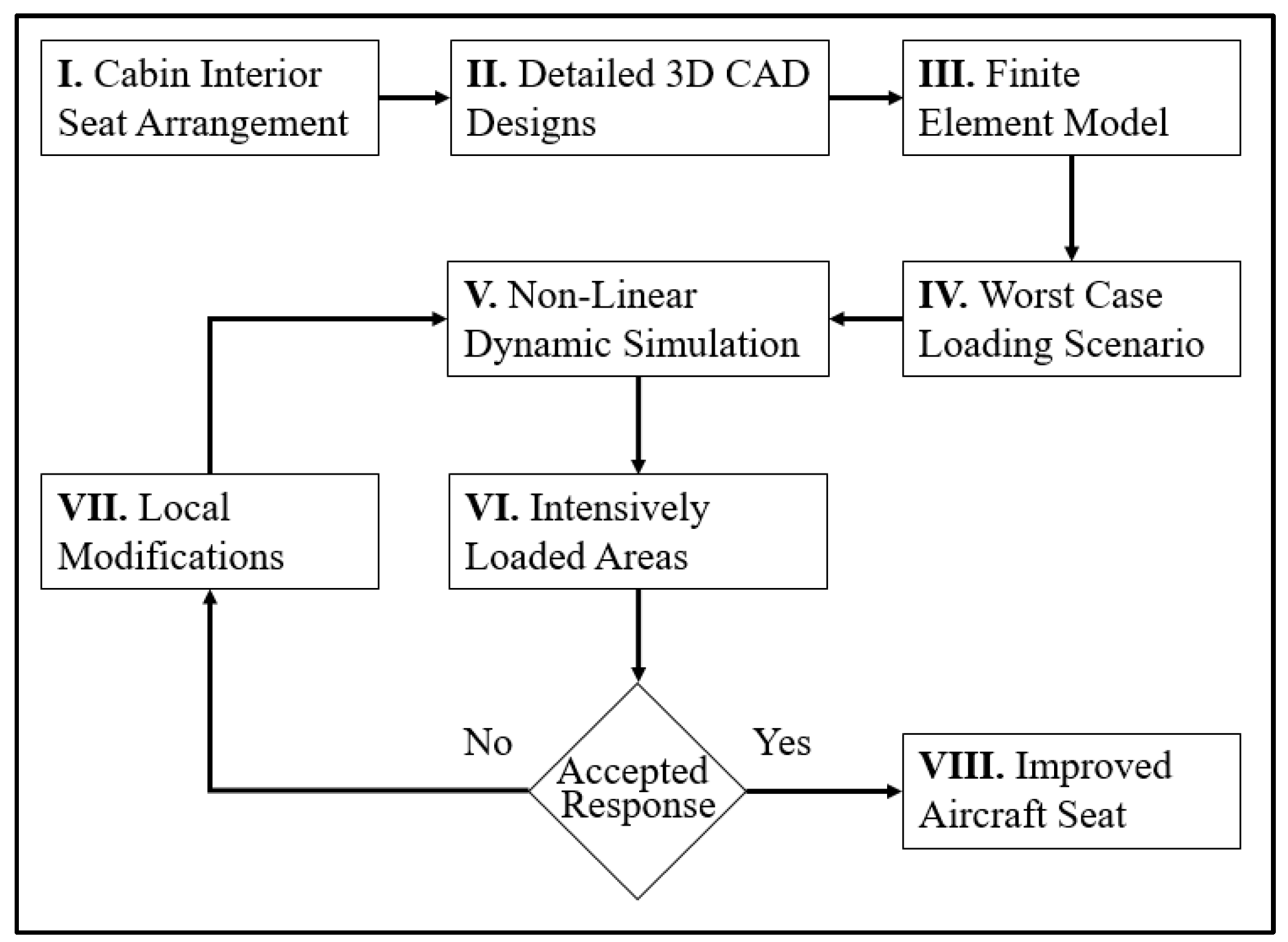
The study model was subjected to a parametric analysis involving design modifications to improve the structural response while complying with the occupant injury criteria. The discrete steps followed are shown in the flow chart of Figure 2.
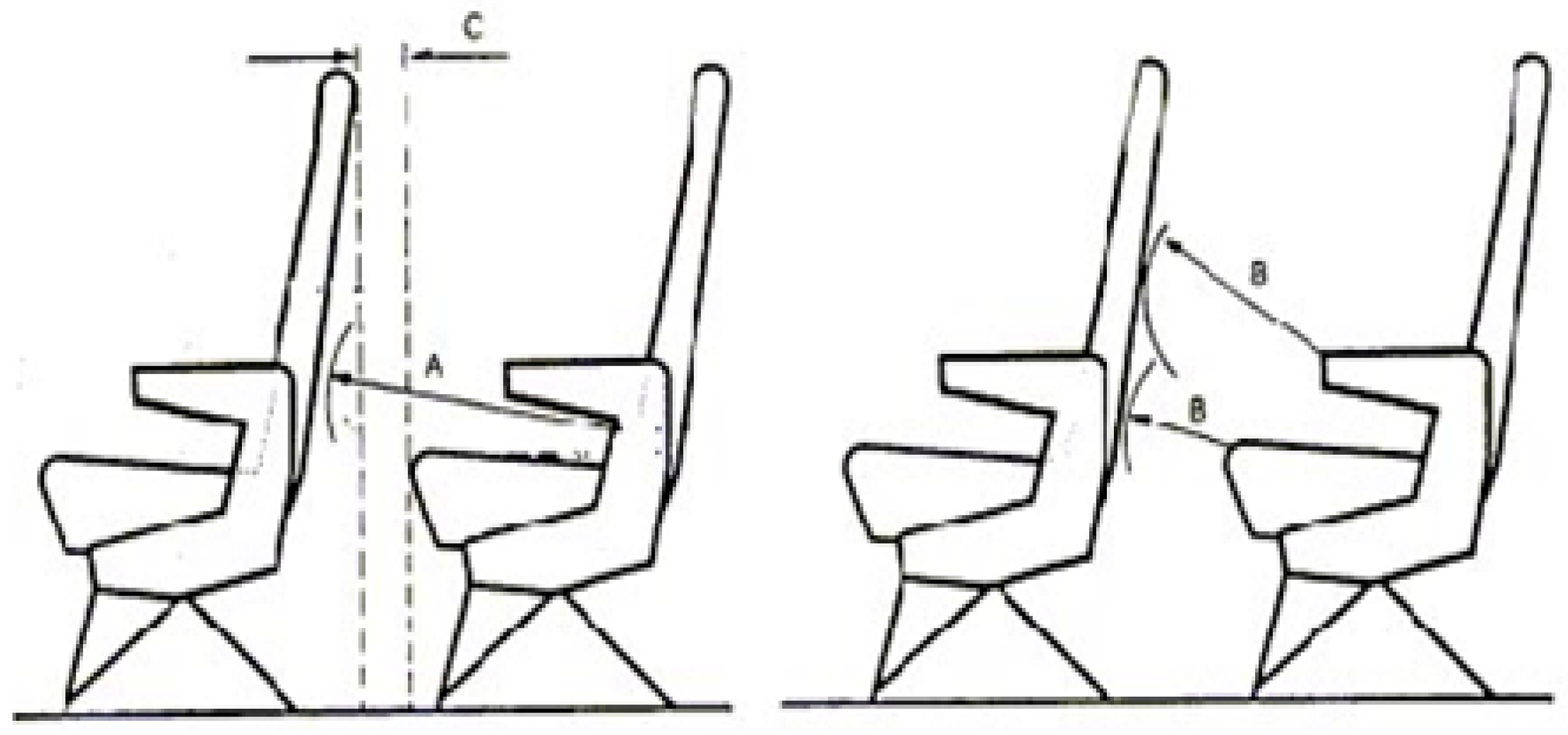
As a first step, the interior of the aircraft cabin is studied regarding the arrangement of the seats, the number of occupants that can be restrained per seat and the seat orientation and distancing. The global dimensions of the seat configuration, such as the width, the length and the distance between two rows of seats, are defined by the aerospace industry and depend on whether the comfort and spaciousness are of high importance. An aircraft cabin with small-sized seats and narrow space between the seat rows can transport more passengers and thus be more profitable for the airline company. For this study, the global distances of the seat rows were chosen with the guidance of the UK Civil Aviation Authority Airworthiness Notice 64 [23], as summarized in Table 3 and depicted in Figure 3.
The study of the structural integrity during an impact can be achieved with the dynamic approach of the event, where the solution is given by nonlinear differential equations. The unknown variables of the problem, such as displacement, velocity and acceleration, are calculated directly by numerical solutions and are used to evaluate the stress, stain and energy of the structure. For the needs of this study, the simulation of the impact dynamic event was achieved with the use of the LS-Dyna explicit integration method. LS-Dyna is a Finite Element Analysis (FEA) package that can numerically approach the static and dynamic response of structural components, where the explicit method is its primary analysis procedure. The main equilibrium equation of a dynamic event is given by Equation (2) [24]:
where is the mass matrix, is the damping matrix, is the stiffness matrix, is the external load, is the acceleration, is the velocity and is the displacement. The numerical approach for the calculation of the unknown variables in LS-Dyna for the explicit method is based on the Central Difference scheme, which directly calculates (without matrix inversion) the value of displacement at time level n + 1 and therefore every other variable of the problem, such as the velocity, acceleration, stress, strain, etc., using Equations (3) and (4):
The FE model was created after a geometry cleaning procedure that was applied to the Computer-Aided Designs (CAD), and several seat attachments were removed from the model since they had no load-bearing contribution, which resulted in the reduction of the computational cost. In addition, the focus in the conceptual study model is the failure of the composite material and the injury criteria obtained from specific metrics from anthropomorphic models. Therefore, the parts of the structure included are the ones capturing the transmittance of the loads in an effort to increase computational efficiency and avoid further complexity that would add further uncertainties to anthropomorphic device kinematics. For this reason, fasteners are represented by contact algorithms assigned a linear elastic stiffness without any damage behavior and are only used to compute the transferred fastener load for detailed analysis, which is beyond the scope of this study [25].
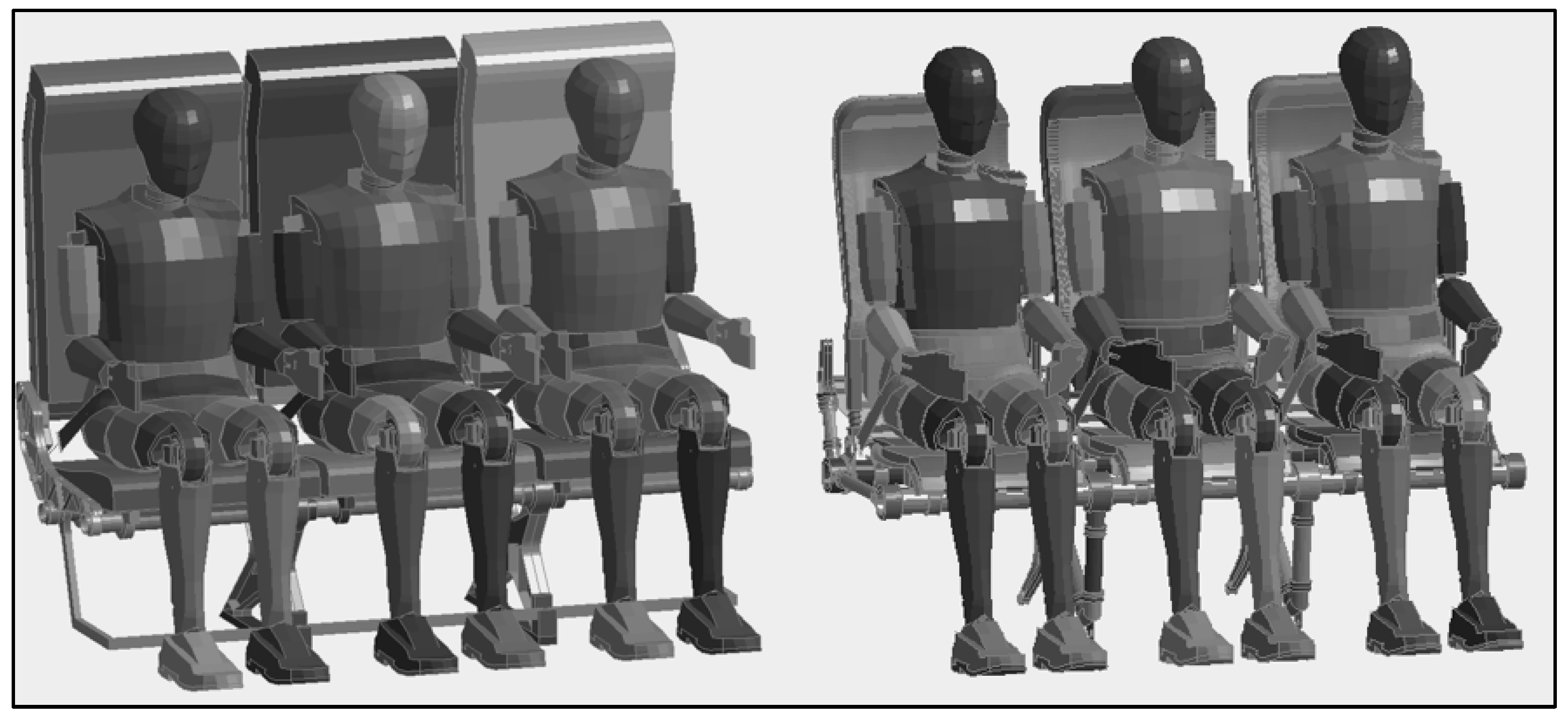
The ATDs that were used are the LSTC Hybrid III 50th Fast Dummies [26,27], and their positioning and seating restraint and the preparation of the dynamic tests were carried out with the guidance of the Advisory Circular (AC) 20-146 [28,29]. The final models of the occupant seats, shown in Figure 4, were used for the non-linear dynamic crash simulations, where the structural response and the biomechanical loading of the dummies were observed, and modifications took place to achieve the satisfaction of the certification criteria.
The finite element model generation was completed with the definition of the constitutive models of the materials concerning their nonlinear response and failure, the element topology parameters and the model boundary conditions.
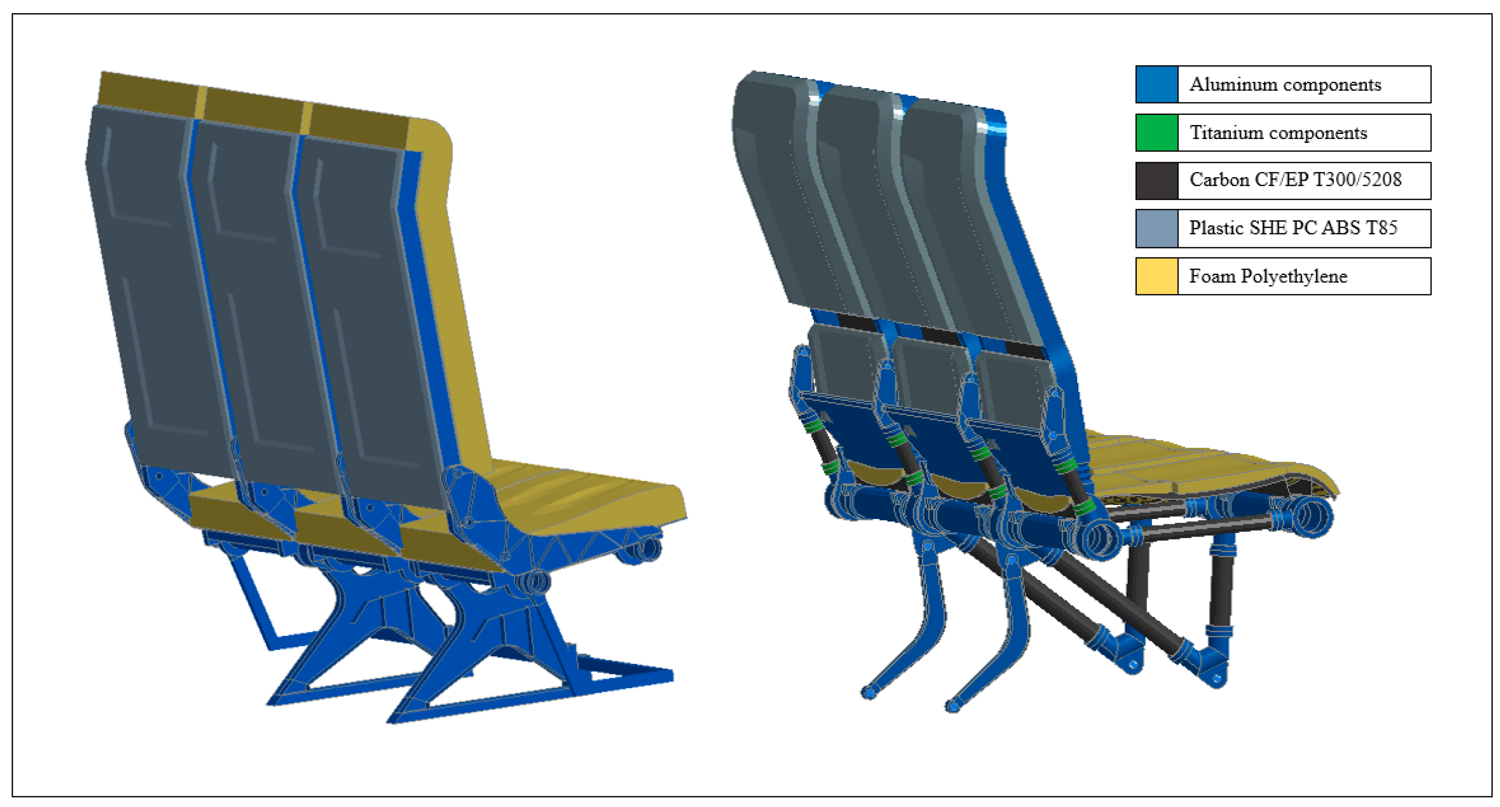
The selection of the materials for the seat structure was carried out with regard to multiple factors that are associated with stiffness, energy absorption and material density. In general, the choice of the right material is made knowing the requirements that the system must fulfil [30]. For the needs of this study, most of the components are composed of aluminum alloys, such as Al 2024-T3, which has an acceptable structural response to the mechanical loads of the study case. For injection molded components such as covers for the main body of the seating, foams for the seat pans and backrests, T85 ABS-Polycarbonate blend was used. The usage of materials in different parts of the seats in both the initial and improved versions is shown in Figure 5.
The mechanical properties of the isotropic materials (Aluminum, plastic T85 and foams) are summarized in Table 4 and Table 5, whereas the properties of the composite material are shown in Table 6.
Isotropic materials were modeled on the von Mises failure criterion, since it predicts, with accuracy, the yield and fracture failure mechanisms [31]. The calculation of von Mises stress is given by Equation (5). Equation (6) gives the yield failure if is less than 1, and Equation (7) gives the fracture failure if is less than 1.
For the composite components, the Material model MAT_54 was used, and their response was evaluated with the Chang–Chang failure criterion that is implemented in LS-Dyna due to its ability to consider failure in the fiber and matrix independently. This material model simulates the progressive damage under crash conditions, where the elements are deleted when the Chang–Chang criterion is fulfilled [32]. The ability to calculate the degradation of the material mechanical properties requires extensive tuning and calibration to produce reliable results [33], and, thus, the composite components of this study were designed to withstand the impact loads without any material failures. The Chang–Chang failure criterion equations are shown in Equations (8)–(11) [24].
Fiber failure Tensile fiber mode, σ11 ≥ 0
Compressive fiber mode, σ11 < 0
Matrix failure Tensile matrix mode, σ22 ≥ 0
Compressive matrix mode, σ22 < 0
Some of the most important considerations that must be taken into account by the Computer-Aided Engineering (CAE) user are the element types and the level of refinement of the mesh. In addition, it is of high importance to define the appropriate number of elements for the mesh in order to ensure the optimum accuracy of the results, which can be achieved with convergence studies. Element convergence studies can aid engineers in establishing the mesh refinement requirements and at the same time aid reviewers in evaluating the quality of the fine element model [34].
For the requirements of this study, the following element formulations from LS-Dyna were used (Table 7) [35]:
The unit system that was used in this study is presented in Table 8 and was determined by the unit system of the LS-Dyna’s ATD.
The convergence study was conducted by splitting the assembly of the structure to individual sub-models, which were studied for their mesh refinement level. The sub-modeling procedure requires analysis results from the initial model, which will be used to clarify the model locations of high interest and the components that are critically loaded. First, the structure is categorized and distinguished by its subcomponents with respect to their location and their role in the overall response of the structure. The study of each distinguished sub-model is achieved with the isolation of the appropriate boundary and loading conditions that can simulate the exact structural response with an integral seat model. In addition, the convergence study was conducted considering the computational capabilities and time-cost of the simulation, while balancing it with the desirable accuracy of the results.
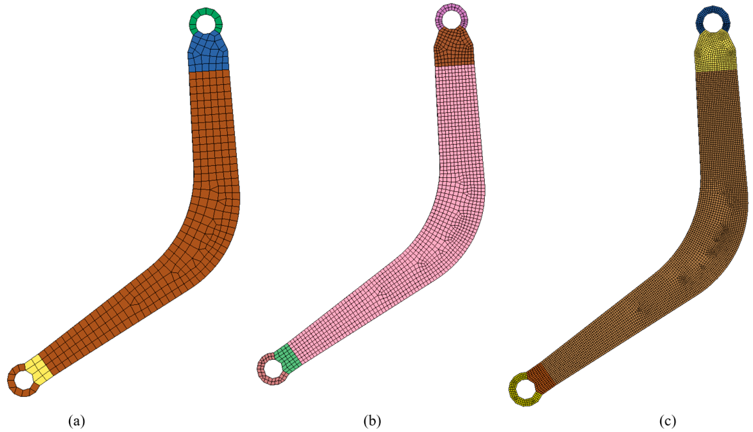
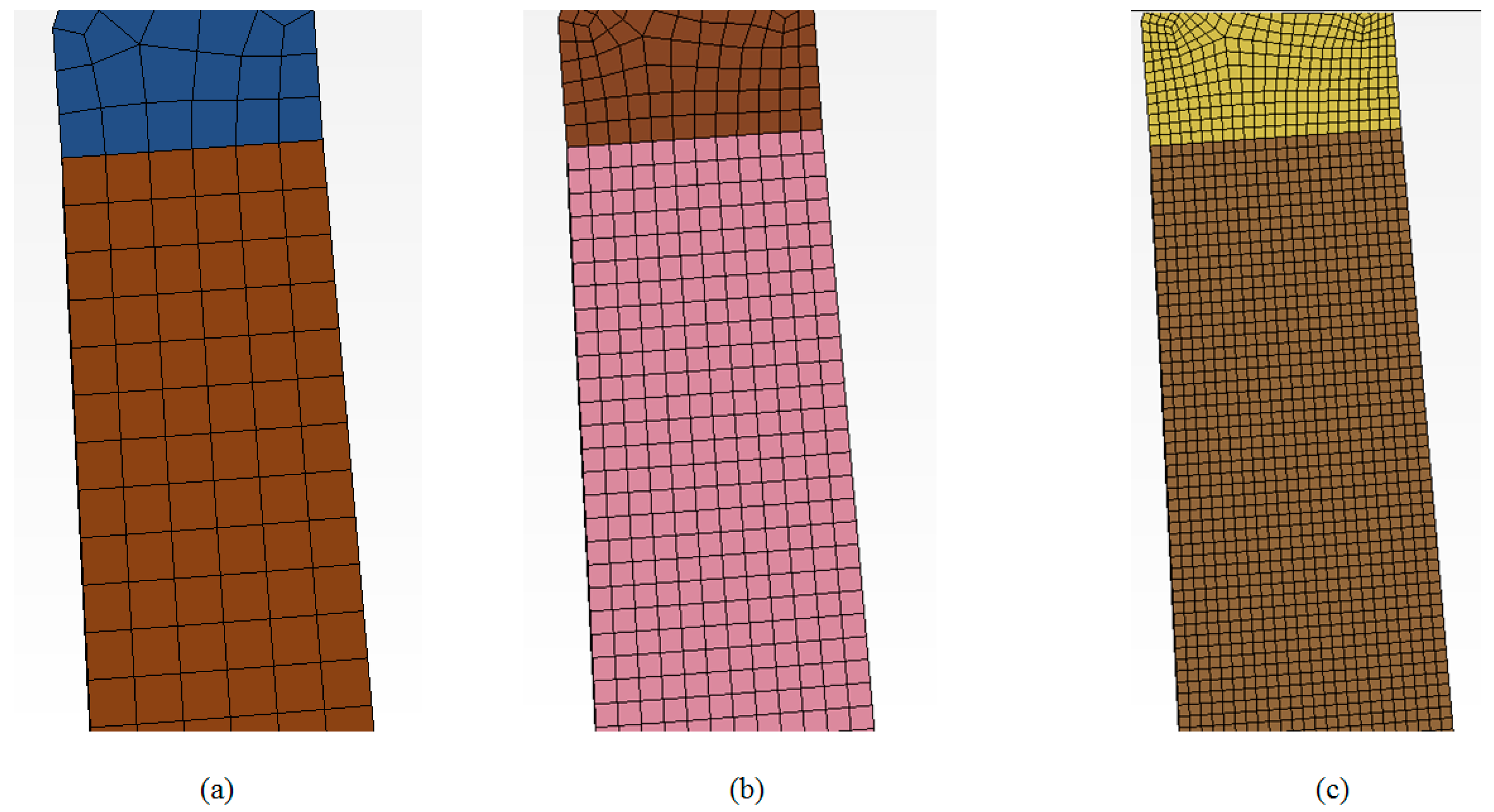
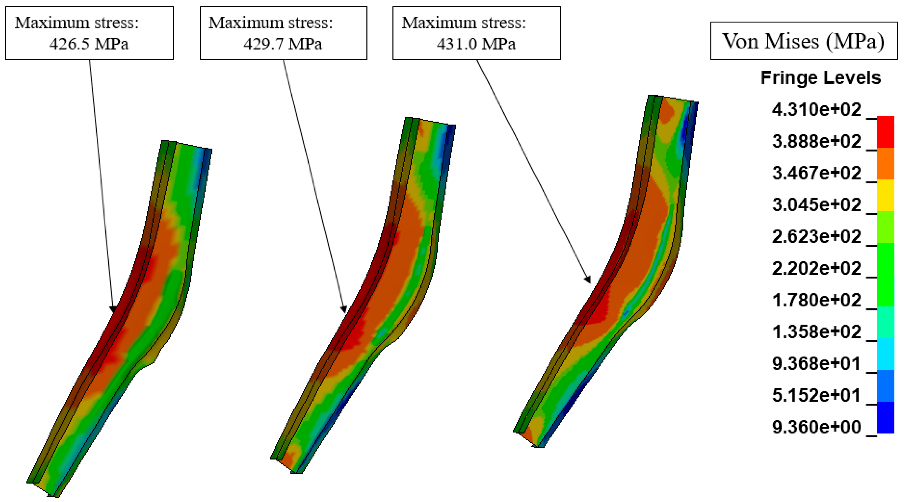
In Figure 6 and Figure 7 are shown the mesh refinement process for the rear legs of the seat structure, which were proved to be the most highly loaded components of the structure. The von Mises stress corresponding to each mesh size is shown in Figure 8 and summarized in Table 9.
The evaluation of the convergence results indicates that the use of the initial mesh, which consists of the fewest finite elements, produces fairly accurate stress results, and the stress fields of the three mesh cases seem to be similar. In addition, it is observed that the computational time that is needed for the analysis changes relative to the number of elements; thus, the mesh that is selected for the analysis of the full model is the one in the first case.
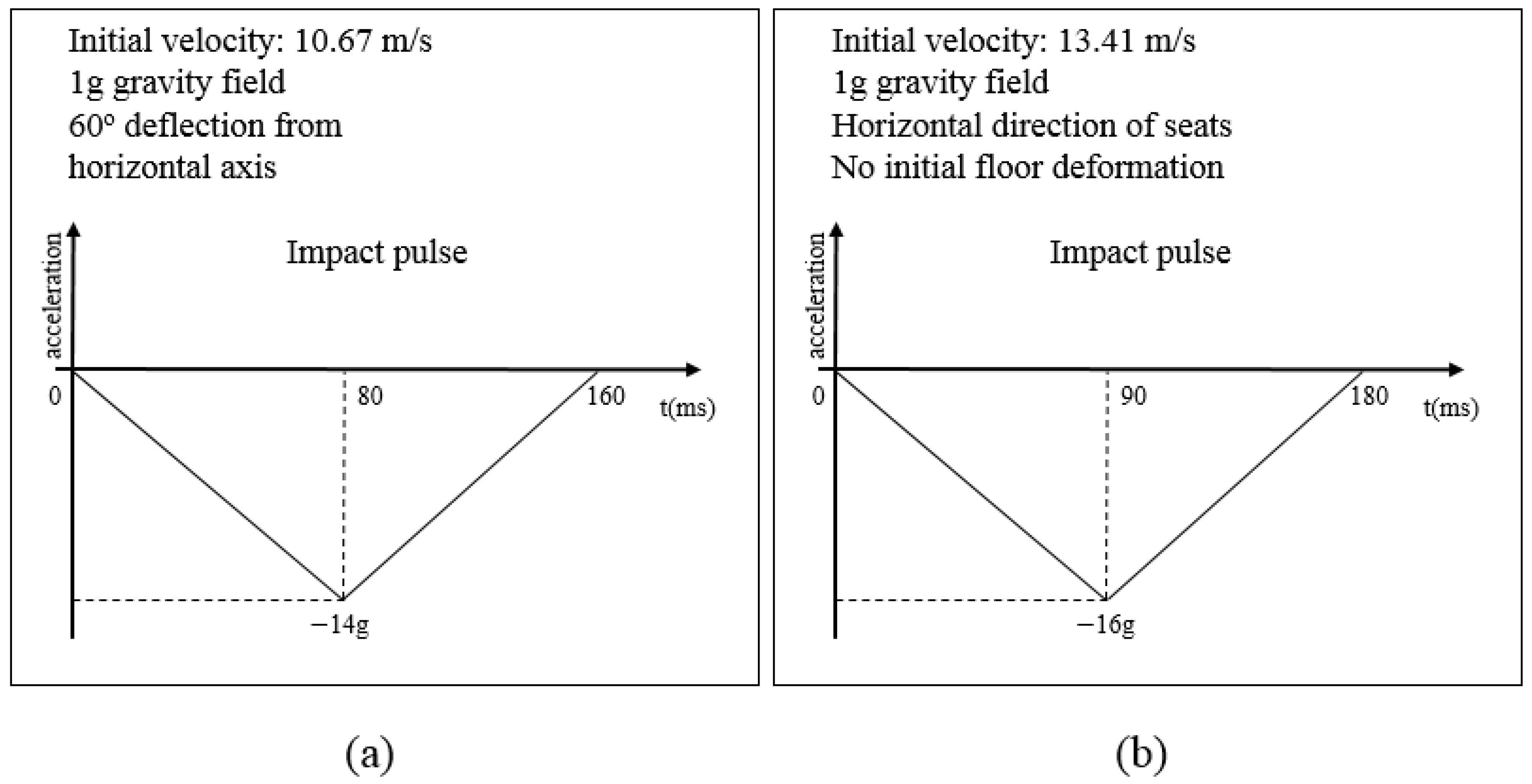
The study of a structural problem requires the definition of its boundary conditions, which are the forces that are required to solve a model or the deformations associated with these forces. In this study, the seating system is considered rigidly attached to the aircraft’s floor, and, thus, restrictions were applied to the degrees of freedom (d.o.f) of the seat leg’s lower structure, While the model was subjected to the application of the gravity field, the prescribed acceleration was 14 g for test 1 and 16 g for test 2 and test 3. Additionally, the applied boundary and loading conditions for the sled tests of this study can be summarized in Figure 9.
3. Results
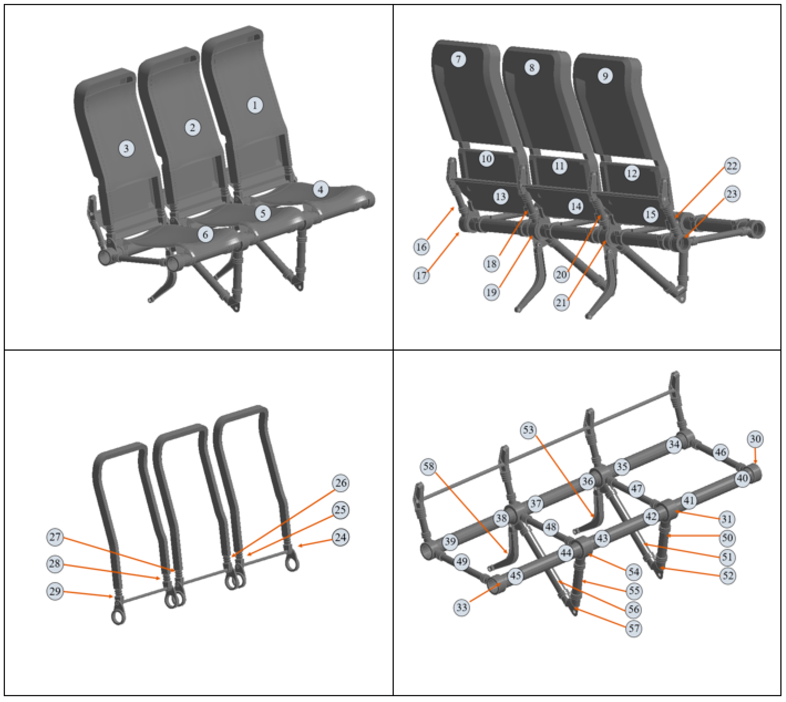
The accurate examination and evaluation of the produced results from the crash simulations require the detection of the most critical areas of the structure. For this reason, the numbering convention of the primary loaded parts of the seat is shown in Figure 10.
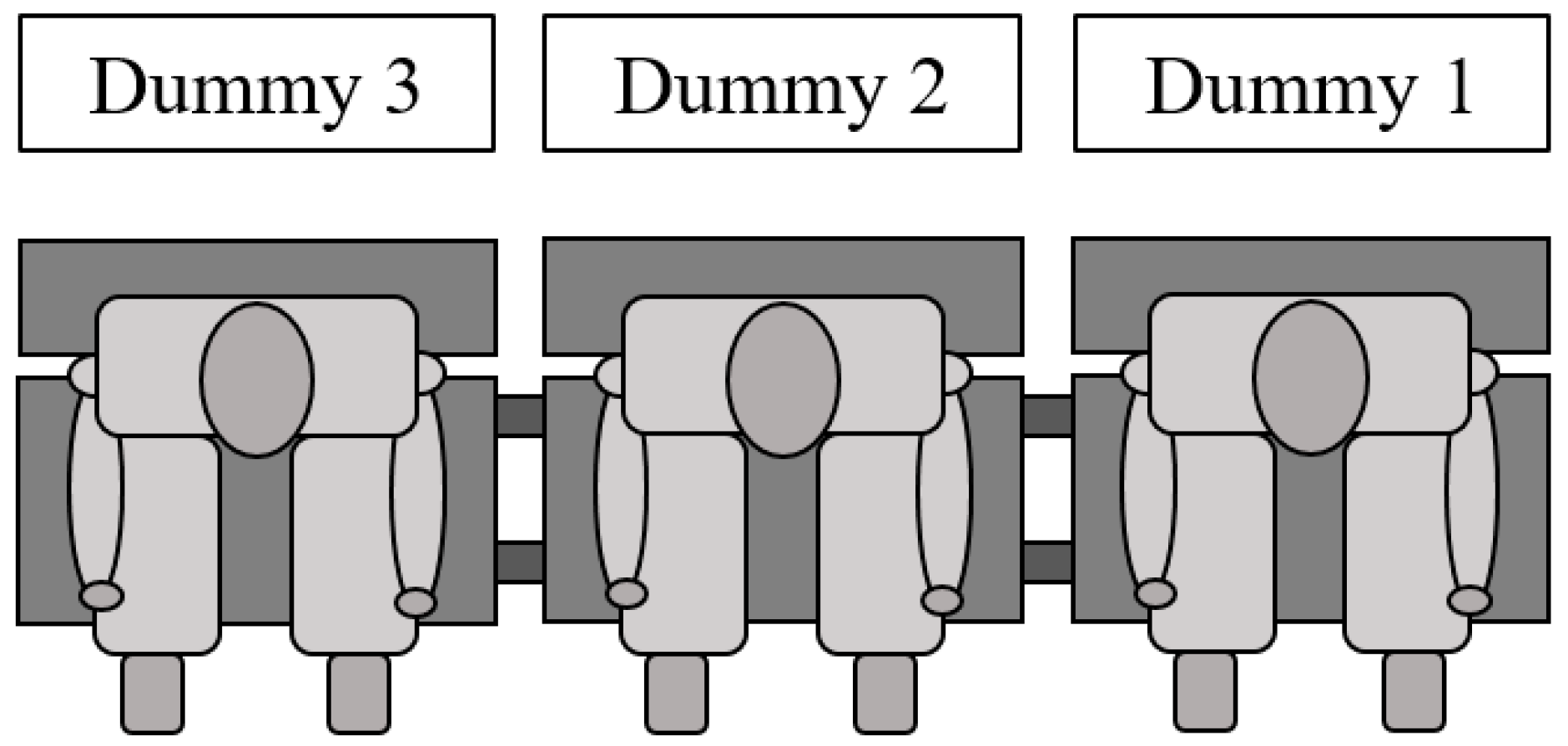
Additionally, regarding the study of the occupant injury criteria, a proper numbering of the dummies is needed. The calculation of the accelerations and loads that apply to the passengers and thus the potential injuries that may occur follows the numbering shown in Figure 11.
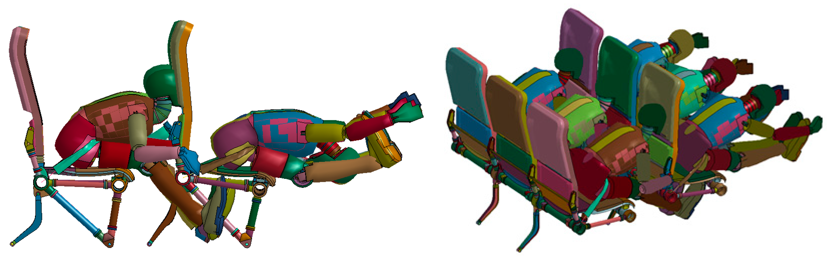
The worst-case scenario, regarding the structure’s loading, is observed in Test 3 for the study of two seat rows, where the frontal seat rows are stressed more intensively than the rear. Except for the examination of the structural response, this simulation also studies the biomechanical forces that apply to the head (HIC) of the rear passengers when they hit their frontal seats, as seen in Figure 12. The materials that were chosen and the geometric characteristics of the backrests make them energy-absorbing and thus smooth the head’s impact and decrease the probability of a serious injury during the event of a minor crash landing. From the kinematical representation of the crash test, it can be assumed that the aircraft seat and all its components remain attached to the main body of the structure. The dummies that represent the hypothetical passengers also remain constrained to their seats.
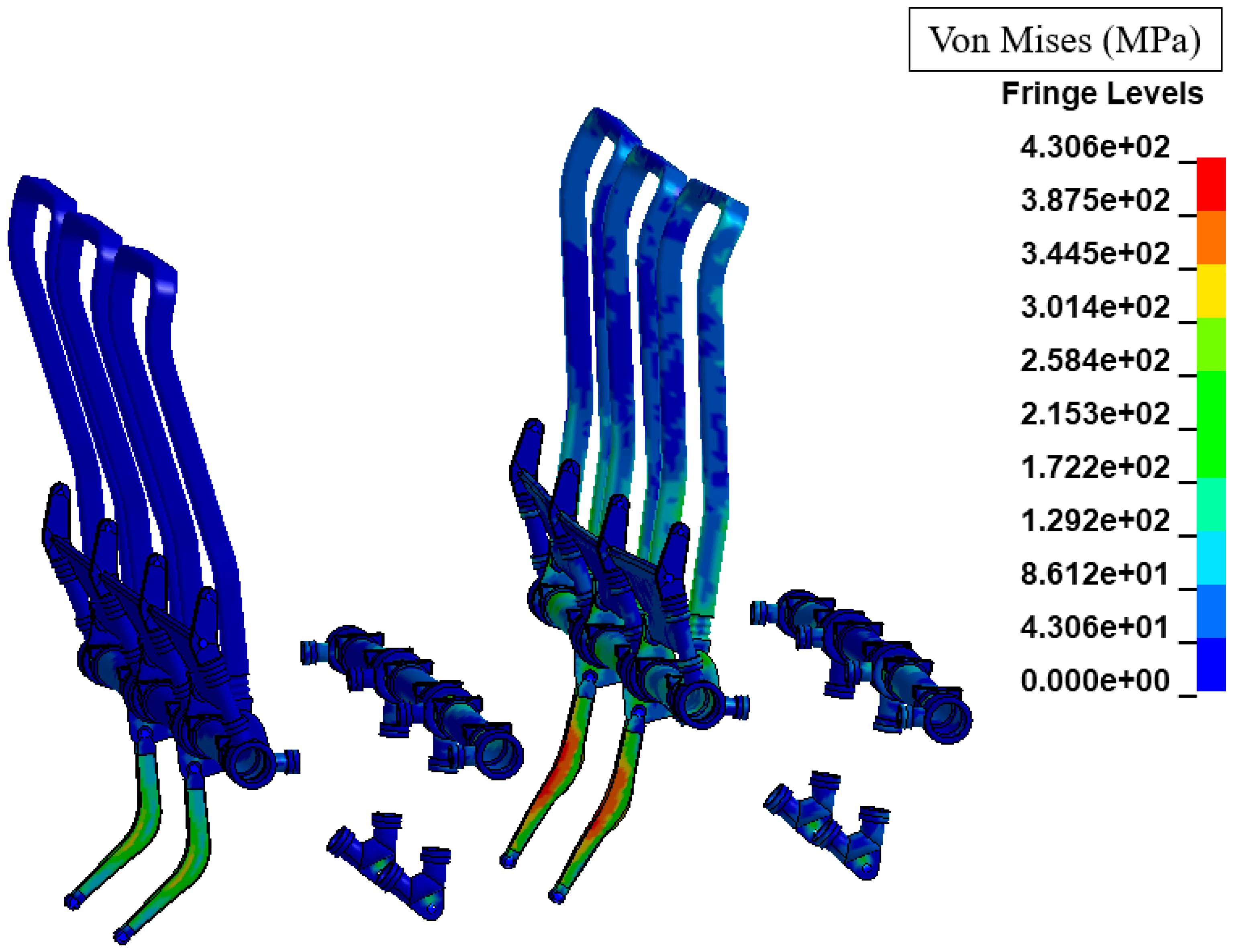
The examination of the stress results shows that the seat structure maintains its integrity and that there are not material failures or critically loaded areas. In addition, the structure’s components that are responsible for the inherent energy-absorbing behavior of the seat configuration exhibit intense plastic deformation, which results in the energy extraction from the system of seat occupants. The frontal seat row has a more intense loading than the rear because it is stressed with both the applied deceleration of the crash test and the impact of the rear passengers, which can be observed in the von Mises stress diagram of Figure 13 and in the study of the safety factor for the isotropic materials of Table 10.
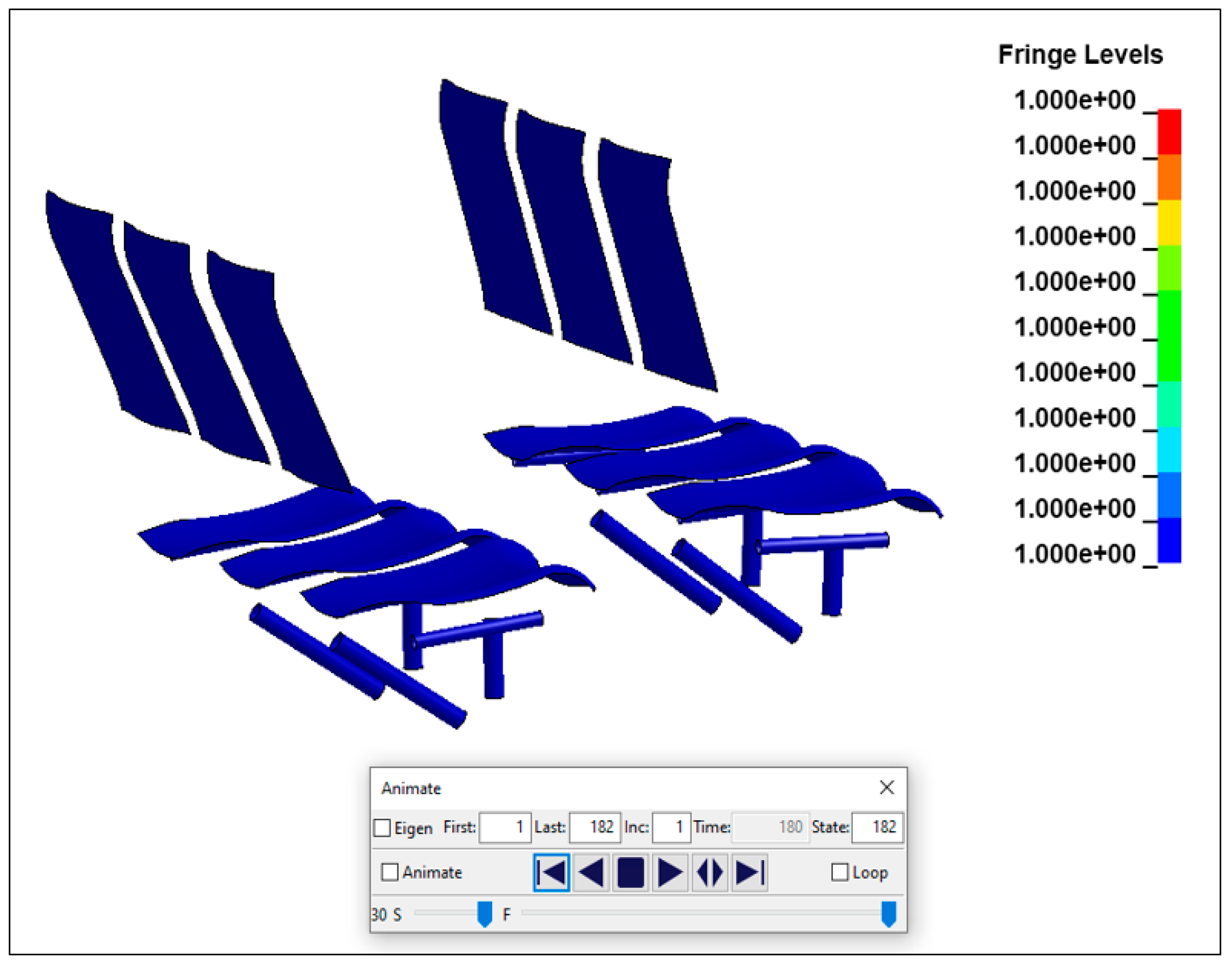
Lastly, the laminated composite components remained intact, without exhibiting any material failure in the matrix or fiber direction. Specifically, the Chang–Chang criterion of the LS-Dyna’s MAT_54 studies the potential types of composite damage separately, which can be examined by the user with the study of the package’s history variables. In Figure 14, the results of the LS-Dyna’s history variable 5 are presented, which indicates the total composite failure for every time-step of the simulation, with its values varying from 0 for total composite failure to 1 for intact material. Considering that, at the last time-step of the simulation (t = 180 ms), there are not any values below 1 in the unit scale, it can be assumed that there are no material failures throughout the impact test [36].
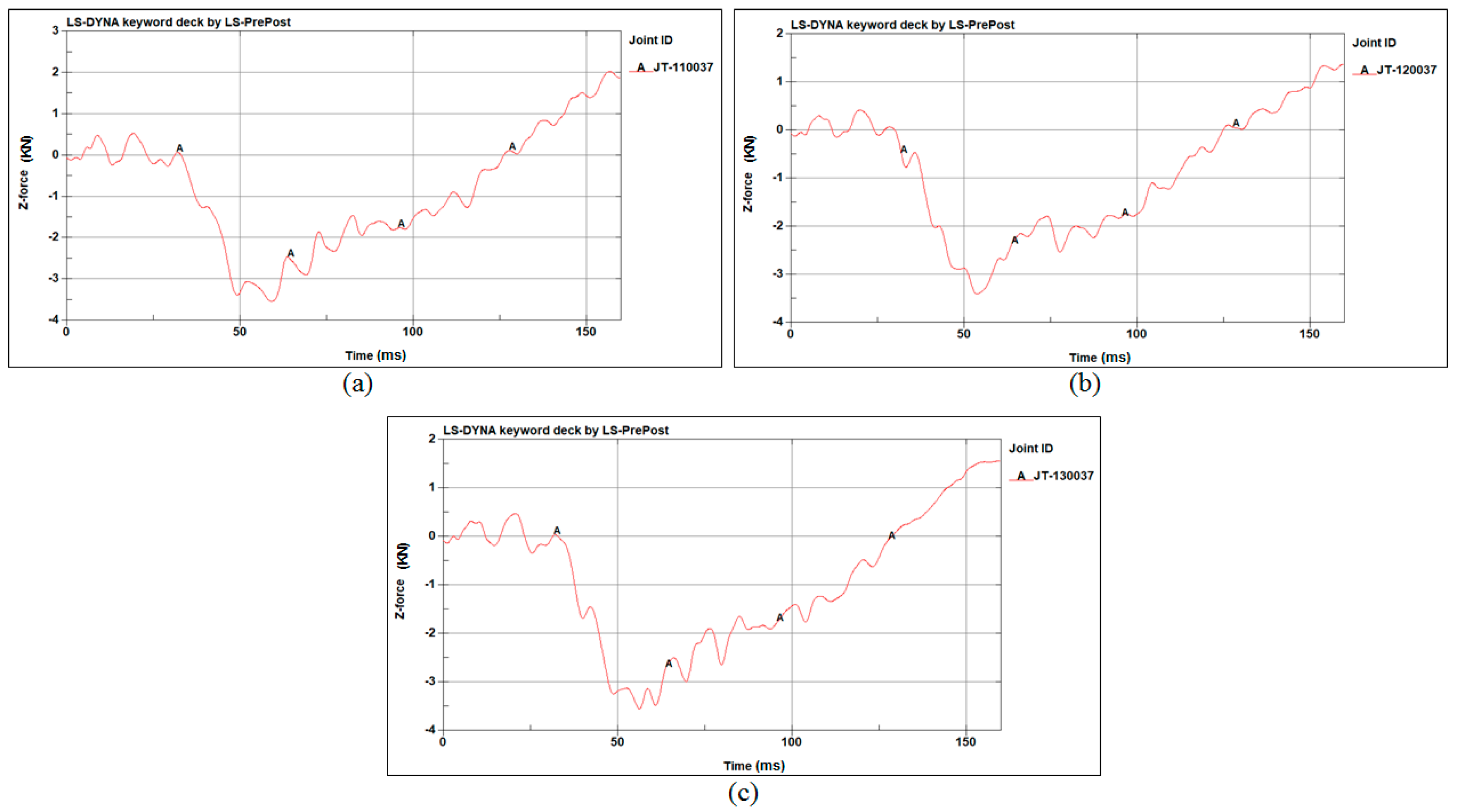
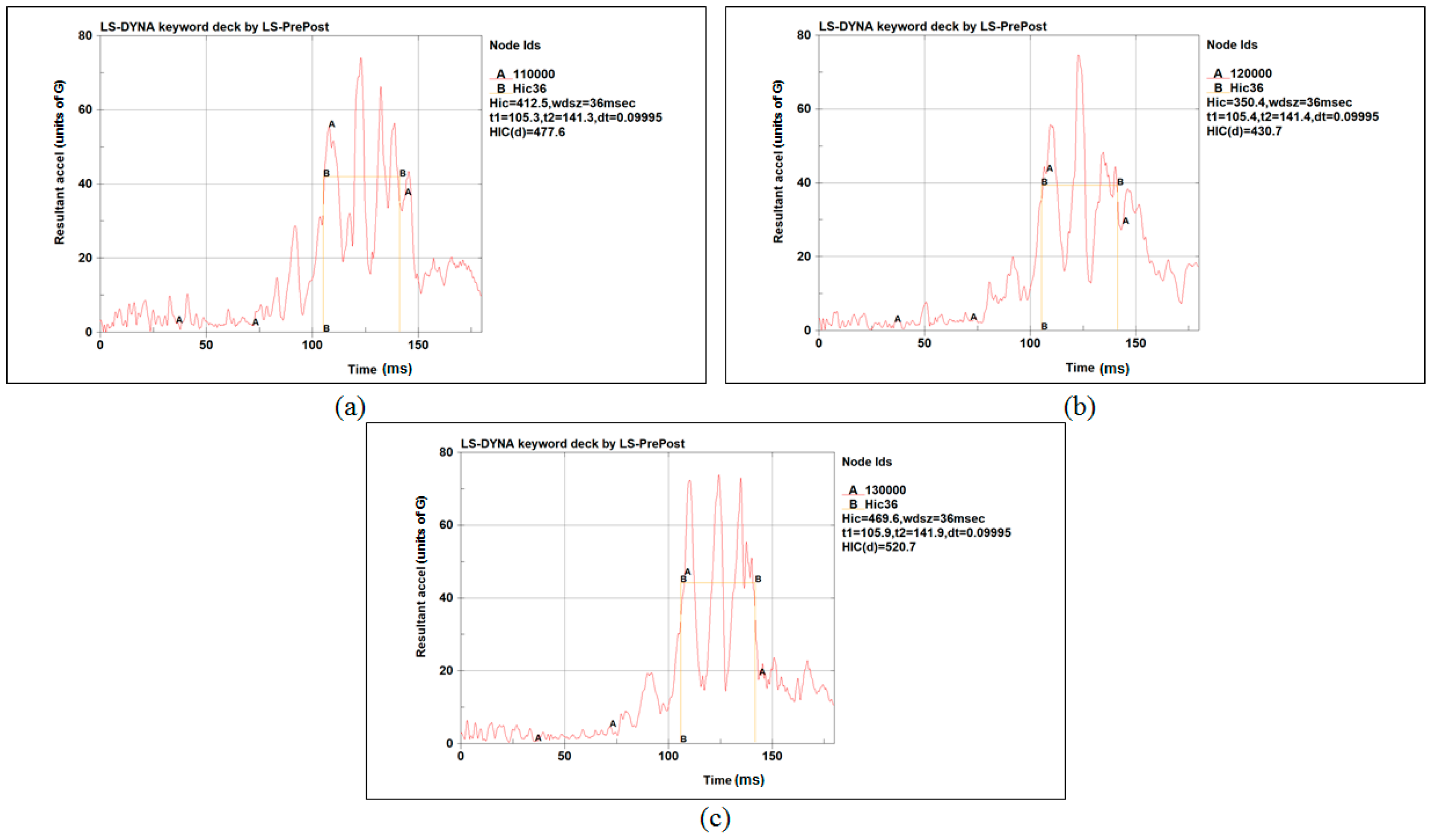
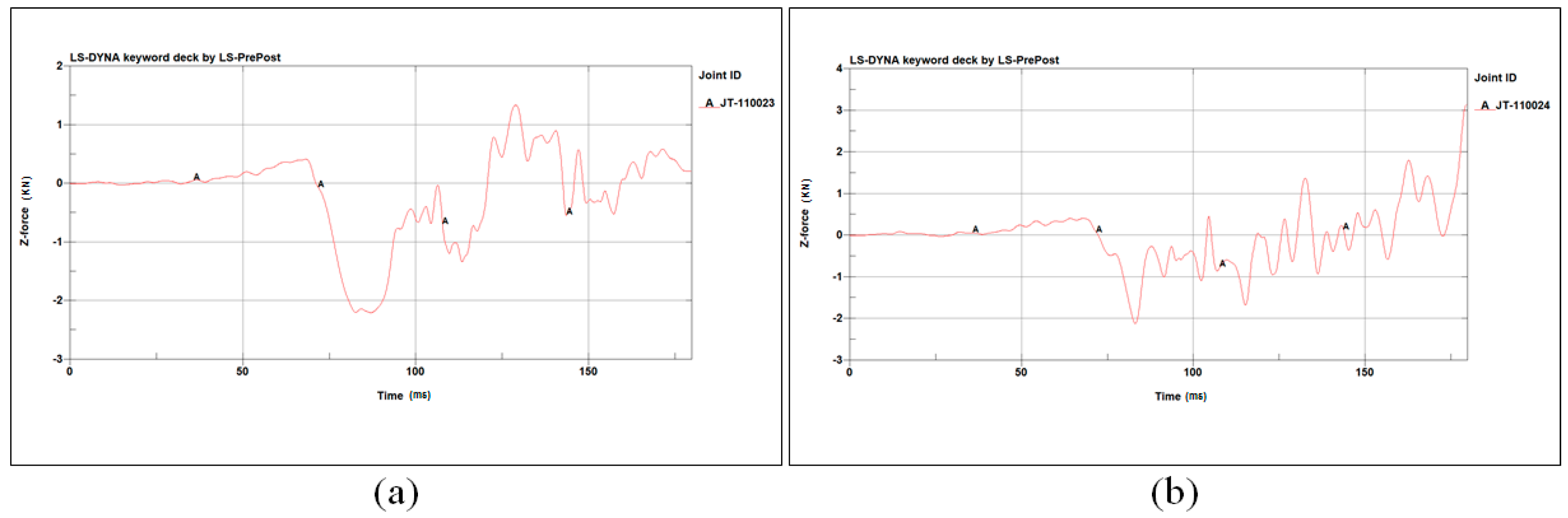
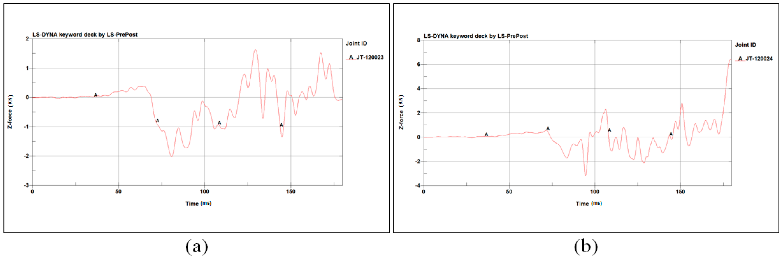
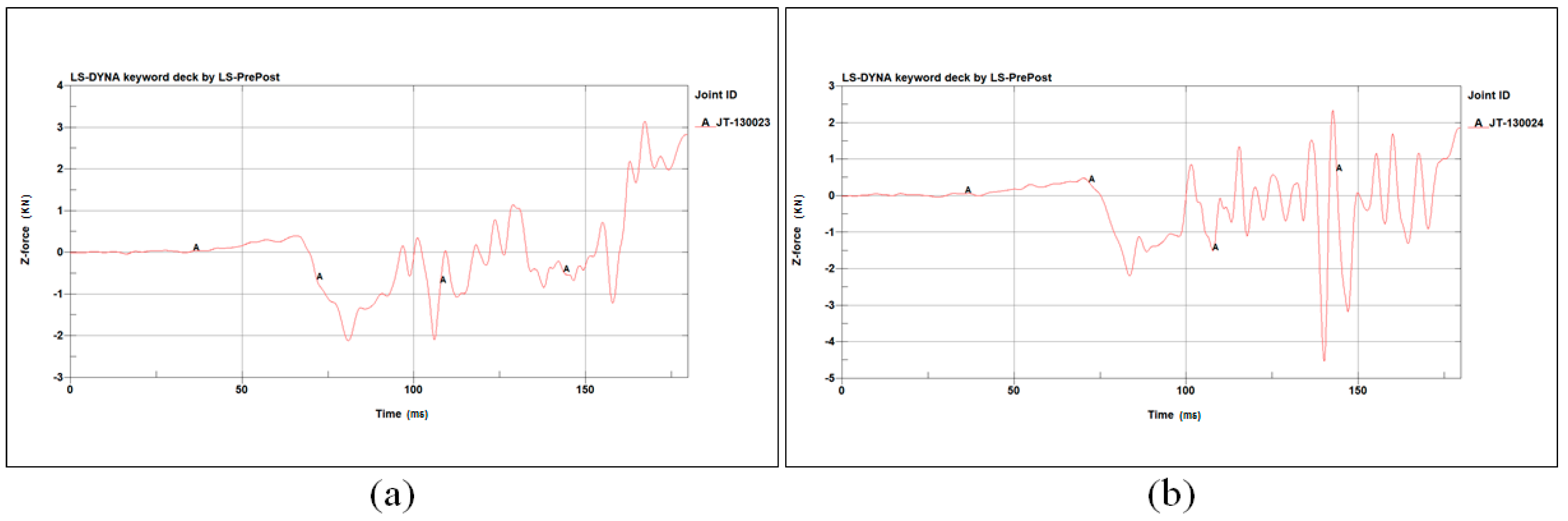
The evaluation of the injury possibility of an occupant during the crash test, with the calculation of the occupant’s lumbar compressive forces in Figure 15, head acceleration in Figure 16 and the femur compressive forces in Figure 17, Figure 18 and Figure 19, is conducted for test 1 and test 3 for the case of the two seat rows. The results from the injury criteria study indicate that the occupants are well protected and that they are likely to survive a minor crash landing (Table 11, Table 12 and Table 13).
4. Weight Reduction
The weight reduction that was achieved with the use of composite materials is approximately 48% and is summarized in Table 14.
5. Discussion
A 27 kg custom design of the aircraft seat exhibits an acceptable mechanical behavior as a matter of structural integrity and occupant safety. There are no major material failures of the isotropic metallic and polymer plastic components that exist in the primary loading path of the seat structure, nor are there minor failures for the anisotropic composites. The aluminum and plastic components that deform intensively and thus enter the plastic region of the material behavior result in the energy absorption of the system seat-occupant and decrease the possibility of the material fracture of the critically stressed areas of the seat or the occurrence of occupant injury. In addition, it should be noted that even though the produced results of the FE simulation are acceptable and promising, the CAE methods cannot replace the full-scale physical tests. However, the methodology that was followed for the design and study of this concept of an aircraft seat model, combined with the satisfaction of FEA reliability factors, such as convergence analysis and FE quality parameters, indicate that the produced model has promising characteristics and thus can proceed to the next steps of the development, such as the enhancement of the FE model and the further reduction of the seats’ weight. Lastly, it should be underlined that the main accomplishment of this study is the parallel replacement of isotropic materials with composites as a means of weight reduction, along with the structural behavior enhancement of the remaining isotropic materials in order to maintain the energy-absorbing behavior of the aircraft seats in the impact event.
Author Contributions
Conceptualization, G.T., A.K. and V.K.; methodology, G.T. and A.K.; software, G.T., A.K. and E.G.; validation, G.T. and A.K.; resources, V.K.; writing—original draft preparation, G.T.; writing—review and editing, G.T. and A.K.; supervision, V.K. All authors have read and agreed to the published version of the manuscript.
Funding
This research received no external funding.
Institutional Review Board Statement
Not applicable.
Informed Consent Statement
Not applicable.
Data Availability Statement
The data presented in this study are available on request from the corresponding author. The data are not publicly available due to pending IP exploitation.
Conflicts of Interest
The authors declare no conflict of interest.
References
- Guida, M.; Marulo, F.; Caprio, F.; Russo, S. Occupants’ Injury during a Drop Test of an Advanced Composite Fuselage Section. Aerotec. Missili Spaz. 2018, 97, 129–134. [Google Scholar] [CrossRef]
- Olschinka, C.; Schumacher, A. Dynamic Simulation of Flight Passenger Seats. In Proceedings of the 5th LS-DYNA Conference, Ulm, Germany, 12–13 October 2006. [Google Scholar]
- Meola, C.; Boccardi, S.; Carlomango, G.M. Composite Materials in the Aeronautical Industry. In Infrared Thermography in the Evaluation of Aerospace Composite Materials; Elsevier Science: Amsterdam, The Netherlands, 2017; pp. 1–24. [Google Scholar]
- Yi, X.S. Development of Multifunctional Composites for Aerospace Application. In Multifunctionality of Polymer Composites; William Andrew: Norwich, NY, USA, 2015; pp. 367–418. [Google Scholar]
- Kassapoglou, C. Design and Analysis of Composite Structures with Applications to Aerospace Structures; Wiley: Hoboken, NJ, USA, 2013; ISBN 9781118401606. [Google Scholar]
- Campbell, F.C. Structural Composite Materials; ASM International: Almere, The Netherlands, 2010. [Google Scholar]
- David Müzel, S.; Bonhin, E.P.; Guimarães, N.M.; Guidi, E.S. Application of the Finite Element Method in the Analysis of Composite Materials: A Review. Polymers 2020, 12, 818. [Google Scholar] [CrossRef] [PubMed] [Green Version]
- Dandekar, C.R.; Shin, Y.C. Modeling of machining of composite materials: A review. Int. J. Mach. Tools Manuf. 2012, 57, 102–121. [Google Scholar] [CrossRef]
- Cook, R.D. Finite Element Modeling for Stress Analysis, 1st ed.; John Wiley & Sons, Inc.: Hoboken, NJ, USA, 1995. [Google Scholar]
- Tenek, L.T.; Argyris, J. Finite Element Analysis for Composite Structures. In Solid Mechanics and Its Applications; Gladwell, G.M., Ed.; Springer: Dordrecht, The Netherlands, 1998; Volume 59. [Google Scholar]
- Zhao, L.G.; Warrior, N.A.; Long, A.C. Finite element modelling of damage progression in non-crimp fabric reinforced composites. Compos. Sci. Technol. 2006, 66, 36–50. [Google Scholar] [CrossRef]
- Mkaddem, A.; Demirci, I.; Mansori, M.E. A micro–macro combined approach using FEM for modelling of machining of FRP composites: Cutting forces analysis. Compos. Sci. Technol. 2008, 68, 3123–3127. [Google Scholar] [CrossRef]
- Zhao, S.Y.; Xue, P. New Two-Dimensional Polynomial Failure Criteria for Composite Materials. Adv. Mater. Sci. Eng. 2014, 2014, 503483. [Google Scholar] [CrossRef] [Green Version]
- Paris, F. A Study of Failure Criteria of Fibrous Composite Materials; NASA/CR-2001-210661; NASA: Hampton, UK, 2001.
- Camanho, P.P.; Dávila, C.G. Mixed-Mode Decohesion Finite Elements for the Simulation of Delamination in Composite Materials; NASA/TM-2002-211737; NASA: Hampton, UK, 2002.
- Madenci, E. Free vibration and static analyses of metal-ceramic FG beams via high-order variational MFEM. Steel Compos. Struct. 2021, 39, 493–509. [Google Scholar] [CrossRef]
- Bhonge, P. A Methodology for Aircraft Seat Certification by Dynamic Finite Element Analysis; Wichita State University: Wichita, KS, USA, 2008. [Google Scholar]
- U.S.Department of Transportation. Federal Aviation Administration. Available online: https://www.faa.gov/ (accessed on 22 June 2022).
- Dhole, N.E. Development and Validation of a Finite Element Model of a Transport Aircraft Seat Under Part 25.562 Dynamic Test Conditions; Wichita State University: Wichita, KS, USA, 2010. [Google Scholar]
- Lamanna, G.; Vanacore, A.; Guida, M.; Caputo, F.; Marulo, F.; Vitolo, B.; Cicatiello, S. Development of a Head Injury Criteria-Compliant Aircraft Seat by Design of Experiments. Aerospace 2019, 6, 95. [Google Scholar] [CrossRef] [Green Version]
- DeWeese, R.; Moorcroft, D.; Philippens, M.M.G.M. Assessment of Head and Neck Injury Potential During Aircraft Longitudinal Impacts; Office of Aerospace Medicine: Washington, DC, USA, 2016.
- Chen, E. Aircraft Seat Row-to-row Head Injury Criteria (HIC) Simulation Using LS-DYNA. In Proceedings of the 15th International LS-DYNA Users Conference, Dearborn, MI, USA, 10–12 June 2018. [Google Scholar]
- Quigley, C.; Southall, D.; Freer, M.; Moody, A.; Porter, J.M. Anthropometric Study to Update Minimum Aircraft Seating Standards; Loughborough University: Loughborough, UK, 2001. [Google Scholar]
- Hallquist, J. LS-DYNA Theory Manual; Livermore Software Technology Corporation: Livermore, CA, USA, 2006. [Google Scholar]
- Camanho, P.; Matthews, F. Stress analysis and strength prediction of mechanically fastened joints in FRP: A review. Compos. Part A Appl. Sci. Manuf. 1997, 28, 529–547, ISSN 1359-835X. [Google Scholar] [CrossRef] [Green Version]
- Guha, S.; Bhalsod, D.; Krebs, J. LSTC Hybrid III 50th Fast Dummy Positioning & Post-Processing; Livermore Software Technology Corporation: Troy, MI, USA, 2011. [Google Scholar]
- Lin, M.P.; Chang, C.M.; Tsai, C.H.; Tai, C.H.; Lee, C.-T. Usage of LSTC_NCAC Hybrid III 50th Dummy in Frontal Ocupant Simulation. In Proceedings of the 13th International LS-DYNA Users Conference, New Taipei City, Taiwan, 5–7 October 2021. [Google Scholar]
- Administration, F.A. Methodology for Dynamic Seat Certification by Analysis for Use in Parts 23, 25, 27, and 29 Airplanes and Rotorcraft; Office of the Federal Register, National Archives and Records Administration: Washington, DC, USA, 2003.
- Dhole, N.; Yadav, V.; Olivares, G. Certification by Analysis of a Typical Aircraft Seat. In Proceedings of the 12th International LS-DYNA Users Conference, Dearborn, MI, USA, 3–5 June 2012. [Google Scholar]
- Erden, S.; Yayla, P. Finite Element Stress Analysis of Airplane Seat. Eur. Mech. Sci. 2021, 5, 6–13. [Google Scholar] [CrossRef]
- Xiang, G.; Pownuk, A.; Kosheleva, O.; Starks, S.A. Von Mises Failure Criterion in Mechanics of Materials: How to Efficiently Use it Under Interval and Fuzzy Uncertainty. In Proceedings of the NAFIPS 2007—2007 Annual Meeting of the North American Fuzzy Information Processing Society, San Diego, CA, USA, 24–27 June 2007. [Google Scholar]
- Feraboli, P.; Wade, B. Crushing Behavior of Laminated Composite Structural Elements: Experiment and LS-DYNA Simulation; DOT/FAA/TC-15/25; U.S. Department of Transportation Federal Aviation Administration Office of Aviation Research: Washington, DC, USA, 2016.
- Feraboli, P.; Wade, B. Simulation Laminated Composite Materials Using LS-DYNA Material Model MAT54: Single-Element Investigation; Federal Aviation Administration: Egg Harbor Township, NJ, USA, 2015.
- Bjorkman, G.; Molitoris, D. Mesh Convergence Studies for Thin Shell Elements Developed by the ASME Task Group on Computational Modeling. In Proceedings of the ASME 2011 Pressure Vessels and Piping Conference, American Society of Mechanical Engineers, Baltimore, MD, USA, 17–21 July 2011. [Google Scholar]
- LSTC. LS-Dyna Keyword User’s Manual Volume I; Livermore Software Technology Corporation: Livermore, CA, USA, 2015. [Google Scholar]
- LSTC. LS-Dyna Keyword User’s Manual Volume II Material Models; Livermore Software Technology Corporation: Livermore, CA, USA, 2015. [Google Scholar]
Figure 1.
Dreamliner and its use of structural composites [4].
Figure 1.
Dreamliner and its use of structural composites [4].

Figure 2.
Methodology flow chart for the improvement of the aircraft seat concept.

Figure 3.
Distancing of aircraft seats [23].
Figure 3.
Distancing of aircraft seats [23].

Figure 4.
Aircraft seat models: Initial study model (left) and improved study model (right).

Figure 5.
Material usage in the initial version (left) and improved version (right).

Figure 6.
Meshing of the rear leg of seat models with (a) 692 elements, (b) 2768 elements and (c) 11,052 elements.
Figure 6.
Meshing of the rear leg of seat models with (a) 692 elements, (b) 2768 elements and (c) 11,052 elements.

Figure 7.
Detailed meshing view of the rear leg of seat models with (a) 692 elements, (b) 2768 elements and (c) 11,052 elements.
Figure 7.
Detailed meshing view of the rear leg of seat models with (a) 692 elements, (b) 2768 elements and (c) 11,052 elements.

Figure 8.
Stress comparison of the seat rear legs using three mesh cases.

Figure 9.
Loading conditions of (a) test 1 and (b) test 2 and test 3.

Figure 10.
Numbering of the primary loading path components.

Figure 11.
Νumbering of Anthropomorphic Test Devices.

Figure 12.
Kinematical response of crash test 3.

Figure 13.
Maximum stress of the primary loading path’s metal components for test 3.

Figure 14.
Failure study of the primary loading path’s composite components for test 3.

Figure 15.
Test 1: Lumbar compressive force (KN) vs. time (ms) of (a) Dummy 1, (b) Dummy 2 and (c) Dummy 3.
Figure 15.
Test 1: Lumbar compressive force (KN) vs. time (ms) of (a) Dummy 1, (b) Dummy 2 and (c) Dummy 3.

Figure 16.
Test 3: HIC curve of (a) Dummy 1, (b) Dummy 2 and (c) Dummy 3.

Figure 17.
Test 3: Dummy 1’s compressive force (KN) vs. the time (ms) of (a) the left femur and (b) the right femur.
Figure 17.
Test 3: Dummy 1’s compressive force (KN) vs. the time (ms) of (a) the left femur and (b) the right femur.

Figure 18.
Test 3: Dummy 2’s compressive force (KN) vs. the time (ms) of (a) the left femur and (b) the right femur.
Figure 18.
Test 3: Dummy 2’s compressive force (KN) vs. the time (ms) of (a) the left femur and (b) the right femur.

Figure 19.
Test 3: Dummy 3’s compressive force (KN) vs. the time (ms) of (a) the left femur and (b) the right femur.
Figure 19.
Test 3: Dummy 3’s compressive force (KN) vs. the time (ms) of (a) the left femur and (b) the right femur.


Table 1.
Summary of the dynamic tests of CFR 25.562.
| Test 1 | Test 2 |
|---|---|
 |  |
| Vertical loading | Horizontal loading |
| Seat rotation: 60° | 10° pitch, 10° yaw, 10° roll |
| Initial velocity: 10.67 m/s | Initial velocity: 13.41 m/s |
| Maximum deceleration: 14 g at 80 ms | Maximum deceleration: 16 g at 90 ms |
| Injury criteria: Spinal loading | Injury criteria: HIC, Femur loading |
Table 2.
Test 3 description.
| Test 3 |
|---|
 |
| Horizontal loading |
| 10° pitch, 10° yaw, 10° roll |
| Initial velocity: 13.41 m/s |
| Maximum deceleration: 16 g at 90 ms |
| Injury criteria: HIC, Femur loading |
Table 3.
Distancing of aircraft seats [23].
Table 3.
Distancing of aircraft seats [23].
| Dimension | Description | Minimum |
|---|---|---|
| A | The minimum distance between the back support cushion of a seat and the back of the seat or another fixed structure in the front | 26 inches (660 mm) |
| B | The minimum distance between a seat and the seat or another fixed structure in the front | 7 inches (178 mm) |
| C | The minimum vertically projected distance between seat rows or between a seat and any fixed structure in front of the seat | 3 inches (76 mm) |
Table 4.
Isotropic materials’ mechanical properties.
| Material | Density | Young Modulus | Ultimate Strength (σSU) | Yield Strength (σSF) | Poisson’s Ratio | Elongation at Break |
|---|---|---|---|---|---|---|
| Aluminum 2024-T3 | 2780 kg/m3 | 73.1 GPa | 483 MPa | 345 MPa | 0.33 | 18% |
| Aluminum 6082-T6 | 2700 kg/m3 | 70.0 GPa | 300 MPa | 255 MPa | 0.33 | 10% |
| Aluminum 7075-T6 | 2810 kg/m3 | 71.7 GPa | 572 MPa | 502 MPa | 0.33 | 11% |
| Titanium 3AL-2.5V | 4480 kg/m3 | 107 GPa | 790 MPa | 690 MPa | 0.33 | 15% |
| PC ABS T85 | 1115 kg/m3 | 2.3 GPa | 54 MPa | 50 MPa | 0.35 | 80% |
Table 5.
Cushion foam’s mechanical properties.
| Material | Density | Compressive Deflection |
|---|---|---|
| Polyethylene foam ETHAFOAM 4191FR | 35.2 kg/m3 | 10% 0.055 MPa |
| 25% 0.069 MPa | ||
| 50% 0.138 MPa |
Table 6.
Composite material T300/5208’s mechanical properties.
| Property | Value |
|---|---|
| Ply thickness, t | 0.125 mm |
| Modulus of elasticity 0°, E1 | 181 GPa |
| Modulus of elasticity 90°, E2 | 10.3 GPa |
| Poisson’s ratio, v12 | 0.28 |
| Shear Modulus, G12 | 7.17 GPa |
| Tensile strength 0°, Xt | 1500 MPa |
| Compressive strength 0°, Xc | 1500 MPa |
| Tensile strength 90°, Yt | 40 MPa |
| Compressive strength 90°, Yc | 246 MPa |
| Shear strength, Sc | 68 MPa |
| Density, ρ | 1760 kg/m3 |
Table 7.
Element formulations used in the models.
| Element Type | Element Formulation |
|---|---|
| Shell elements | Formulation (2) Belytscho–Tsay |
| Solid elements | Formulation (1) Constant stress solid element & Formulation (2) Fully integrated S/R solid |
| Beam elements | Formulation (1) Hughes–Liu with cross-section integration |
| 1D seatbelt elements | Seatbelt formulation |
| 2D seatbelt elements | Formulation (9) Fully integrated Belytscho–Tsay membrane |
Table 8.
Unit system.
| Mass | Length | Time | Force | Stress | Energy | Gravity |
|---|---|---|---|---|---|---|
| kg | mm | ms | kN | GPa | ΚN-mm | 9.806 × 10⁻³ |
Table 9.
Convergence study results.
| Element Number | Maximum Stress, Von Mises | Computational Time | Hardware |
|---|---|---|---|
| 692 elements | 426.5 MPa | 35 s | DDR4 24 GB RAMIntel core i7-6700K, 4.00 GHz |
| 2768 elements | 429.7 MPa | 144 s | |
| 11,052 elements | 431.0 MPa | 550 s |
Table 10.
Isotropic material safety factor against the fraction for test 3.
| Seat Component Location | Material | Frontal Seat Row Safety Factor | Rear Seat Row Safety Factor |
|---|---|---|---|
| 7 | PC ABS T85 | 1.10 | 5.56 |
| 8 | PC ABS T85 | 1.12 | 7.66 |
| 9 | PC ABS T85 | 1.07 | 5.04 |
| 10 | PC ABS T85 | 1.12 | 2.82 |
| 11 | PC ABS T85 | 1.12 | 1.95 |
| 12 | PC ABS T85 | 1.17 | 4.35 |
| 13 | Aluminum 6082-T6 | 1.63 | 1.80 |
| 14 | Aluminum 6082-T6 | 1.57 | 2.38 |
| 15 | Aluminum 6082-T6 | 1.22 | 1.22 |
| 17 | Titanium 3AL-2.5V | 3.51 | 11.62 |
| 19 | Titanium 3AL-2.5V | 3.24 | 13.39 |
| 21 | Titanium 3AL-2.5V | 3.97 | 13.28 |
| 23 | Titanium 3AL-2.5V | 3.50 | 13.37 |
| 24 | Aluminum 2024-T3 | 1.41 | 4.47 |
| 25 | Aluminum 2024-T3 | 1.40 | 3.83 |
| 26 | Aluminum 2024-T3 | 1.40 | 4.95 |
| 27 | Aluminum 2024-T3 | 1.40 | 4.47 |
| 28 | Aluminum 2024-T3 | 1.39 | 3.72 |
| 29 | Aluminum 2024-T3 | 1.41 | 4.09 |
| 30 | Aluminum 7075-T6 | 2.60 | 2.05 |
| 31 | Aluminum 7075-T6 | 2.50 | 1.40 |
| 32 | Aluminum 7075-T6 | 2.49 | 2.04 |
| 33 | Aluminum 7075-T6 | 2.32 | 2.25 |
| 34 | Aluminum 2024-T3 | 1.50 | 3.80 |
| 35 | Aluminum 2024-T3 | 1.67 | 5.60 |
| 36 | Aluminum 2024-T3 | 1.73 | 5.08 |
| 37 | Aluminum 2024-T3 | 1.64 | 5.55 |
| 38 | Aluminum 2024-T3 | 1.68 | 4.31 |
| 39 | Aluminum 2024-T3 | 1.50 | 3.83 |
| 40 | Aluminum 2024-T3 | 2.68 | 3.80 |
| 41 | Aluminum 2024-T3 | 1.37 | 1.45 |
| 42 | Aluminum 2024-T3 | 1.53 | 1.52 |
| 43 | Aluminum 2024-T3 | 1.45 | 1.57 |
| 44 | Aluminum 2024-T3 | 1.37 | 1.47 |
| 45 | Aluminum 2024-T3 | 2.30 | 4.03 |
| 52 | Aluminum 2024-T3 | 1.40 | 1.80 |
| 53 | Aluminum 2024-T3 | 1.13 | 1.37 |
| 56 | Aluminum 2024-T3 | 1.42 | 1.67 |
| 57 | Aluminum 2024-T3 | 1.12 | 1.38 |
Table 11.
Summary of Test 1: Lumbar maximum compressive force values.
| Dummy Position | Lumbar Compressive Load | Critical Value |
|---|---|---|
| 1 | −3.53 KN | −6.67 KN |
| 2 | −3.40 KN | −6.67 KN |
| 3 | −3.54 KN | −6.67 KN |
Table 12.
Summary of Test 3: HIC injury criteria values.
| Dummy Position | HIC | Critical Value |
|---|---|---|
| 1 | 477.6 units | 1000 units |
| 2 | 430.7 units | 1000 units |
| 3 | 520.7 units | 1000 units |
Table 13.
Summary of Test 3: Femurs’ maximum compressive force values.
| Dummy Position | Left Femur Compressive Load | Right Femur Compressive Load | Critical Value |
|---|---|---|---|
| 1 | −2.19 KN | −2.12 KN | −10.012 KN |
| 2 | −1.99 KN | −3.15 KN | −10.012 KN |
| 3 | −2.06 KN | −4.51 KN | −10.012 KN |
Table 14.
Weight calculations for the assembly of the three-seat configuration models.
| Structural Component | Model 1 Weight (kg) | Model 2 Weight (kg) | Weight Reduction |
|---|---|---|---|
| Back rests | 15 | 8.42 | 43.8% |
| Seat pans | 13.6 | 6.93 | 49.0% |
| Spreaders | 4.73 | 4.45 | 5.9% |
| Tubular axis | 6 | 2.62 | 56.3% |
| Seat legs | 12.67 | 4.61 | 63.6% |
| Total | 52 | 27.02 | 48% |
Disclaimer/Publisher’s Note: The statements, opinions and data contained in all publications are solely those of the individual author(s) and contributor(s) and not of MDPI and/or the editor(s). MDPI and/or the editor(s) disclaim responsibility for any injury to people or property resulting from any ideas, methods, instructions or products referred to in the content. |
© 2022 by the authors. Licensee MDPI, Basel, Switzerland. This article is an open access article distributed under the terms and conditions of the Creative Commons Attribution (CC BY) license (https://creativecommons.org/licenses/by/4.0/).
Share and Cite
MDPI and ACS Style
Tzanakis, G.; Kotzakolios, A.; Giannaros, E.; Kostopoulos, V. Structural Analysis of a Composite Passenger Seat for the Case of an Aircraft Emergency Landing. Appl. Mech. 2023, 4, 1-19. https://doi.org/10.3390/applmech4010001
AMA Style
Tzanakis G, Kotzakolios A, Giannaros E, Kostopoulos V. Structural Analysis of a Composite Passenger Seat for the Case of an Aircraft Emergency Landing. Applied Mechanics. 2023; 4(1):1-19. https://doi.org/10.3390/applmech4010001
Chicago/Turabian StyleTzanakis, Georgios, Athanasios Kotzakolios, Efthimis Giannaros, and Vassilis Kostopoulos. 2023. "Structural Analysis of a Composite Passenger Seat for the Case of an Aircraft Emergency Landing" Applied Mechanics 4, no. 1: 1-19. https://doi.org/10.3390/applmech4010001