Article

Mechanical Properties of Translucent Zirconia: An In Vitro Study

1
Department of Dentistry, Albanian University, 1001 Tirana, Albania
2
Department of Innovative Technologies in Medicine & Dentistry, University “G. d’Annunzio” of Chieti-Pescara, 66100 Chieti, Italy
3
Electron Microscopy Laboratory, University “G. d’Annunzio” of Chieti-Pescara, 66100 Chieti, Italy
*
Author to whom correspondence should be addressed.
Prosthesis 2023, 5(1), 48-59; https://doi.org/10.3390/prosthesis5010004
Submission received: 4 December 2022 / Revised: 3 January 2023 / Accepted: 4 January 2023 / Published: 10 January 2023
(This article belongs to the Special Issue Novel Zirconia Materials Applied in Dental Prostheses)

Abstract

:
Background: The introduction of translucent zirconia has improved mimetics: nevertheless, a reduction in the mechanical performance was registered. The study aim was to investigate the mechanical characteristics of a high-translucent zirconia used for monolithic restorations before and after the aging process compared to a low-translucent zirconia. Methods: A total of 23 specimens were used in the present study. Group A (n = 10) was made of a high-translucent Y-TZP; group B (n = 7) was made of a low-translucent Y-TZP and finally group C (n = 6) was an aged high-translucent Y-TZP. Flexural strength, fracture toughness, brittleness, microcrack’s propagation and grain size were analyzed. Results: The Vickers hardness was: 1483 ± 187 MPa (group C); 1102 ± 392 MPa (group A); 1284 ± 32 MPa (group B). The flexural strength was: 440 (±96.2) MPa (group C); 427 (±59.5) MPa (group A); 805 (±198.4) MPa (group B). The fracture toughness was: 5.1 (±0.7) MPa.m1/2 (group C); 4.9 (±0.9) MPa.m1/2 (group A); 8.9 (±1.1) MPa.m1/2 (group B). The brittleness was: 295 (±42.8) (group C), 230.9 (±46.4) (group A) and 144.9 (±20.3) (group B). The grain size was: 2.75 (±1.2) µm2 (group A); 0.16 (±0.05) µm2 (group B); 3.04 (±1.1) µm2 (group C). Conclusions: The significant reduction in the mechanical properties of high-translucent zirconia, compared to the traditional one, suggests their use in the anterior/lateral area (up to premolars).

1. Introduction

For many years, porcelain-fused-to-metal (PFM) restorations have been the only choice of aesthetic restoration, notwithstanding some aesthetic limitations [1,2]. To overcome these limitations, new aesthetic materials—without a metal core (metal free) and with improved biological characteristics—have been made available [3,4]. Metal-free prosthetic materials include a wide range of glass ceramics, such as lithium disilicate (LS2), zirconia reinforced lithium silicate (ZLS) and polycrystalline materials, such as zirconia and alumina [5]. Chemically, zirconia is a metal oxide with polymorphism and allotropy properties. In dentistry, it is defined as an “all-ceramic” material. Moreover, it has different crystallographic structures such as monoclinic (m), tetragonal (t) and cubic (c) that could differentiate the mechanical and optical characteristics [6,7]. Zirconium dioxide above 2370 °C assumes the cubic structure, the tetragonal is between 2370 and 1170 °C and the monoclinic one is below 1170 °C. Therefore, while it is cooled to room temperature, it assumes the monoclinic structure, a stable crystalline configuration; although, unfortunately, it is poorly resistant to repeated mechanical stress [7]. Over the years, different types of stabilizers (or dopants) applied to zirconia have been studied and nowadays the most used in dentistry are: Yttrium cation-doped Tetragonal Zirconia Polycrystals (Y-TZP), Magnesium cation-doped Partially Stabilized Zirconia (Mg-PSZ) and Zirconia Toughened Alumina (ZTA) [3,8]. Polycrystalline Tetragonal Zirconia stabilized with Yttria (Y-TZP) shows optimal mechanical properties and a remarkable fracture resistance, from 5 to 10 MPa.m1/2, as well as a flexural strength of 900–1400 MPa [9,10]. The fact of reserving the metastable tetragonal structure even at room temperature means having the possibility to hinder the microcrack propagation inside the material body in case of repeated mechanical stresses [1,2,11]. Passerini [12] and Ruff et al. [13] tried to increase the stabilization by adding small percentages of other “stabilizing oxides”. Generally, when zirconia undergoes the transformation from tetragonal to monoclinic (austenitic-- > martensitic), there is an increase in grain volume of about 3–5% [6,7]. The phase shift and the associated grain-volume increase has also been associated with the microcrack closure mechanism [6,14]. For this reason, zirconia is defined as self-healing and very resistant material. The described mechanism occurs only for tetragonal zirconia, since this phase shift cannot take place for cubic zirconia. From an aesthetic point of view, zirconia as a monolithic material has limitations due to its opacity. Recently, improvements have been made with zirconia Prettau (Zirkonzahn GmbH, Gais, Italy), a tetragonal polycrystalline partially stabilized zirconia with yttrium and aluminium, which has both a high translucency and flexural strength of 1200 MPa. The greatest translucency, nevertheless, is a property of cubic zirconia, because it has a cubic structure identical to that of zircon, which is the synthetic substitute for diamond. In general, translucency is one of the main factors in aesthetic dentistry and is critical for the choice of restoration materials. In the last few years, many studies have reported the clinical performance of zirconia ceramic restorations and the fracture rates of ceramic veneer (chipping) in the posterior region [9,10,11,15,16,17,18]. To reduce the incidence of chipping, all zirconia (monolithic) restorations have been recently introduced [6]. Y-TZP shows clear aesthetic advantages and more resistance when compared to other metal alloys [17,18,19]. Furthermore, zirconia placed in contact with soft tissues showed the best response in terms of their health and aesthetics [20]. The fine granulometry (grain size) and the absence of porosity of Y-TZP make it suitable for biomedical applications [21,22,23]. Meanwhile, when in contact with water, Y-TZP is subject to degradation, due to the transformation of the metastable tetragonal zirconia into the monoclinic form [24]. This phenomenon was first detected by Kobayashi et al. [25] and it is called “low-temperature degradation” (LTD) or “aging”. Translucent zirconia is usually used without the porcelain layers, which results in being directly exposed to the oral cavity, raising the problem of LTD and the possible abrasiveness of this material against the antagonist teeth [15,26,27,28]. To date, despite the efforts made by manufacturer’s to make zirconia significantly more translucent, the transmittance values of these materials still do not reach those of glass ceramics [29]. Starting from the evidence in the literature on the susceptibility of the zirconia-ceramic restorations to chipping and taking into account the positive effect of the high-translucent zirconia in aesthetic dentistry, the aim of the present study was to evaluate both the mechanical and microstructural characteristics of this high-translucent zirconia.

2. Materials and Methods

2.1. Study Design and Sample Preparation

In this study, we compared two types of polycrystalline tetragonal zirconia stabilized with Yttria (Y-TZP): high-translucent Prettau Anterior zirconia (Zirkonzahn GmbH, Gais, Italy) and low-translucent Diazir zirconia (Diadem SAS, Louey, France), with composition reported in Table 1.
A total of 30 samples with a rectangular shape (21 mm × 4 mm × 1 mm) were prepared. Twenty for high-translucent zirconia and 10 for low-translucent zirconia. After being finished and polished, 3 specimens from the high-translucent group and 4 specimens from the low-translucent group were lost or damaged. The remaining specimens were divided into three groups as follows: group A, high-translucent Y-TZP (n = 10); group B, low-translucent Y-TZP (n = 7); group C, aged high-translucent Y-TZP (n = 6).

2.2. Aging Process

To evaluate the LTD phenomenon on high-translucent zirconia, artificial accelerating aging was performed using cycles in an autoclave for 5 h at 134° and 0.2 MPa (Euronda R9 Recorder sterilizer, Euronda, Vicenza Italy) according to ISO standards 13356 and to the statement reported in the literature: 1 h at 134 °C corresponds to 3–4 years of in-vivo function [24,25,30].

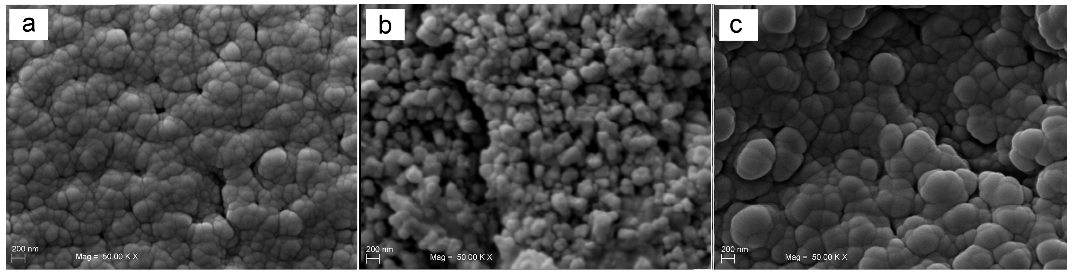
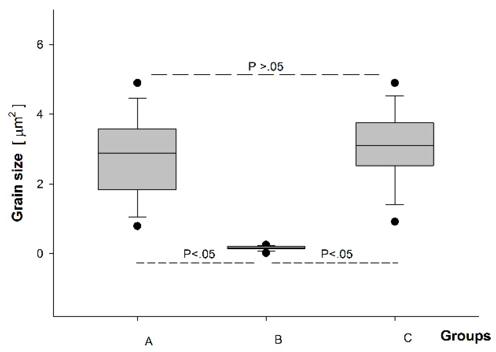
2.3. Grain Size Measurements

Grain size was calculated using a scanning electron microscope (SEM) (EVO 50 XVP with LaB6; Carl Zeiss S, Oberkochen, Germany) according to a previously described procedure [31]. Briefly, the samples were sputter coated with gold (K 550; Emitech Ltd., Ashford, Kent, UK) before evaluation. The SEM set-up included a tetra solid-state back-scattered electron detector operating at 30 kV accelerating voltage, 10 mm working distance and 270 pA probe current. The images were captured at a magnification of (50,000×) as TIFF files using a digital image process. Stored images were measured using a dedicated software, Image-Pro Plus version 6.0 (Media Cybernetics Inc., Bethesda, MD, USA), in order to calculate the grain size. A total of 42 random measurements for each group were made.

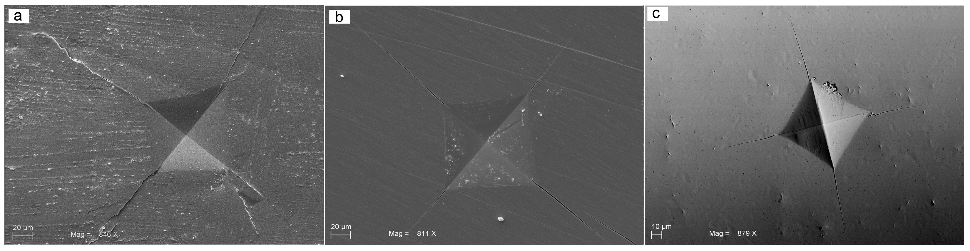
2.4. Vickers Hardness

One hundred and twenty-two Vickers indentations were made on each group. The indentations were made using a diamond Vickers pyramid (Angle 136° and area-depth ratio A = 24.5 hc2) fixed with the load cell at a universal testing machine (Lloyd 30K, Lloyd Instruments, Segensworth, UK) under a constant load of 50 N for 10 sec in a controlled displacement mode at 0.5 mm/min. To determine the stress intensity present at the crack due to the indentation, the crack tip profile was determined using SEM. The length of radial cracks emanated from each of the four-indented corner sources were measured using Image-Pro Plus ver. 6.0 (Media Cybernetics, Bethesda, MD, USA). To ensure accuracy, the software was calibrated for each experimental image using a software feature named “Calibration Wizard”, which reported the number of pixels between two selected points (scale bar). The linear remapping of the pixel number was used to calibrate the distance in microns. The necessary measurements for the calculation of the Vickers hardness values were carried out according to the Equation (1):
V H N = 2 P s i n   ( θ 2 ) L 2 = 1.854 P / L 2
where “L” is the diagonal average length of the indentation, “P” the load in kilogram-force (kgf) and “θ” the angle of the indenter (136°). The execution of the Vickers indentations during the microhardness test was carried out aligned, so it was possible to generate microcracks with a coherent course. By this way, it is possible to observe whether or not the mode of macroscopic fracture of the samples is influenced by the direction of the microcracks.

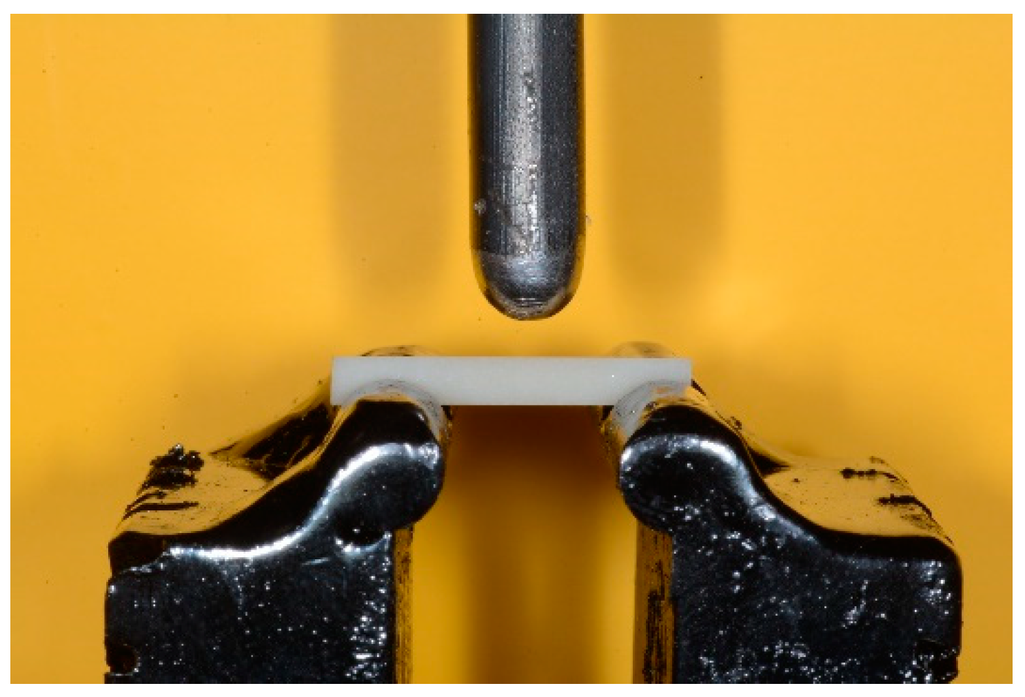
2.5. Flexural Strength

Flexural strength was determined using the three-point bending flexural test carried out using a universal testing machine (Lloyd LR30K universal testing machine, AMETEK Test & Calibration Instruments, Bognor Regis, UK) equipped with a 500 kN load cell and a crosshead speed of 1 mm/min, according to the ISO 6872 specification. For the execution of three-point bending tests, an ad hoc support (Figure 1) was designed and realized, following the specifications suggested by ISO6872: 5 mm diameters rollers, an inter-support distance greater than at least 10 times the thickness of the sample and a spherical head-loading piston with a diameter of 5 mm. Before the execution of each test, the dimensions of individual samples were measured with a precision digital calliper with an accuracy of 0.01 mm. The average bending-strength values were calculated according to the ISO 6872, using Equation (2):
σ = 3 P l 2 w b 2
where “P” is the load at which the fracture of the sample occurred, “l” is the distance between the two cylindrical supports on which the sample is placed, measured from centre-to-centre, “w” the sample diameter and “b” is the sample thickness.

2.6. Fracture Toughness

Fracture Toughness is the property that quantifies the ability of a material to resist the propagation of a pre-existing microcrack under stress conditions. It was calculated using cracks produced by the hardness indents. It was reported as K1C; the “1′′ stands for mode one (uniaxial) and the “C” stands for critical. It was defined as the critical value of the stress intensity factor at a crack tip necessary to produce catastrophic failure using uniaxial loading [6]. To measure the fracture toughness, a previously published method was used [6] by applying Equation (3):
K 1 C = β 0 ( P l ) 1 2
where “P” was the applied load, “l” was the crack length from the tip of the indentation to the crack end, and “β0” was an empirical parameter, usually set equal to 7 for a Vickers indenter. The measurement units of K1C are MPa.m1/2.

2.7. Brittleness

The brittleness (or index of fragility) B i of a material is defined as the measure of the relative susceptibility of the material to fracture [32]. A fragile material tends to poorly absorb energy and deform. Thus, the brittleness in the present study was calculated according to Equation (4):
B i = H v K 1 C
where “Hv” is the Vickers hardness and “K1C” the fracture toughness of the sample under examination.

2.8. Statistical Analysis

The results are shown as mean and standard deviation. For each variable, variance, normality and equality were assessed. The differences in mean values among the groups were analysed. A one-way ANOVA followed by a post hoc Tukey test was applied for multiple comparisons. The threshold value to detect statistically significant differences was set at p < 0.05.
Statistical analysis was performed using the computerized statistical software, SPSS (Vers. 24.0-IBM Corp., Armonk, NY, USA).

3. Results

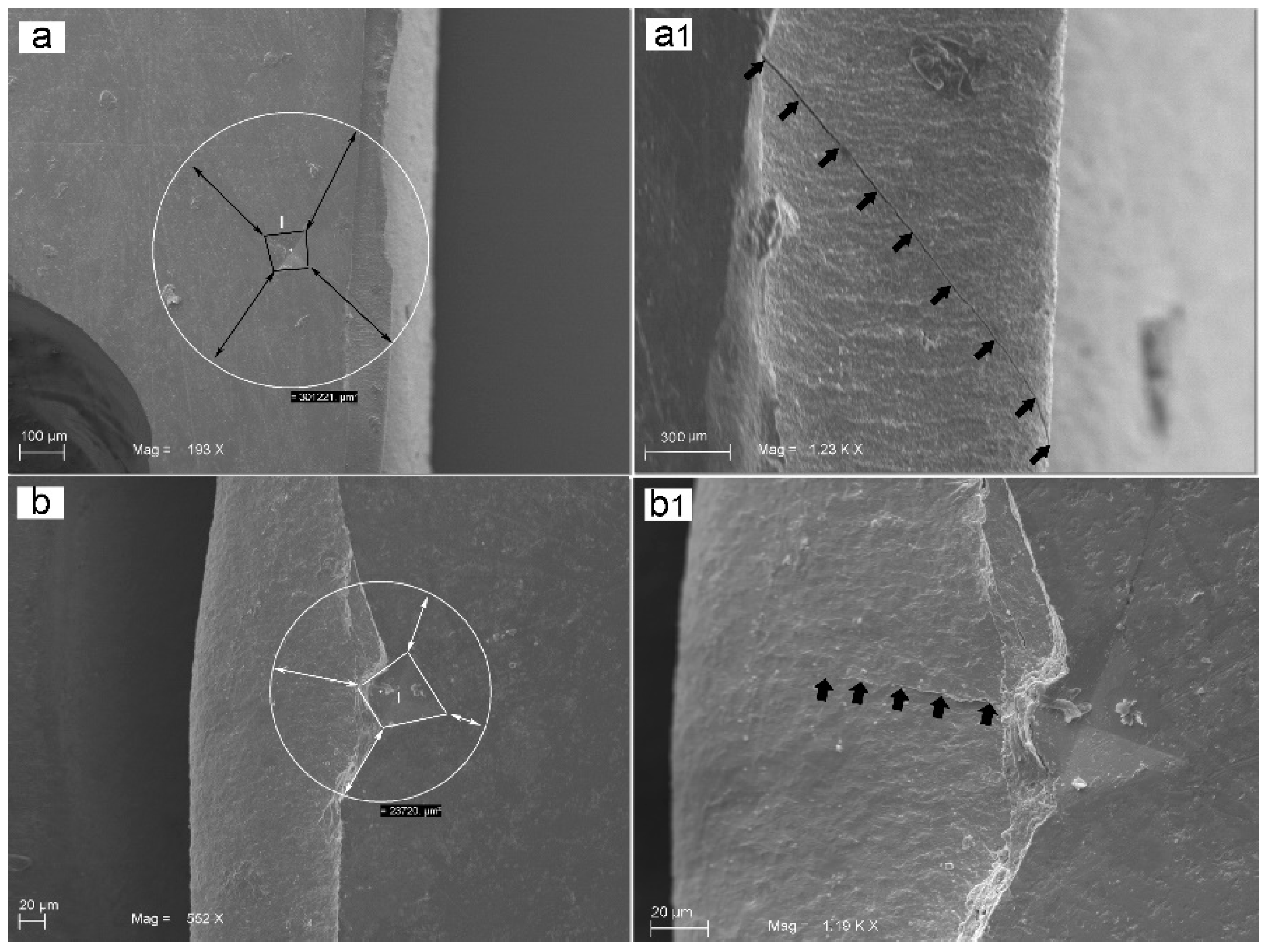
3.1. Grain Size Measurements

The grain size (mean ±SD) measured under SEM (Figure 2) was: for group A, 2.75 (±1.2) µm2; for group B, 0.16 (±0.05) µm2; for group C, 3.04 (±1.1) µm2. The statistical evaluation showed a significant difference between groups A and C versus B (p < 0.05), while no statistically significant difference was present between groups A and C (before and after aging) (Figure 3).

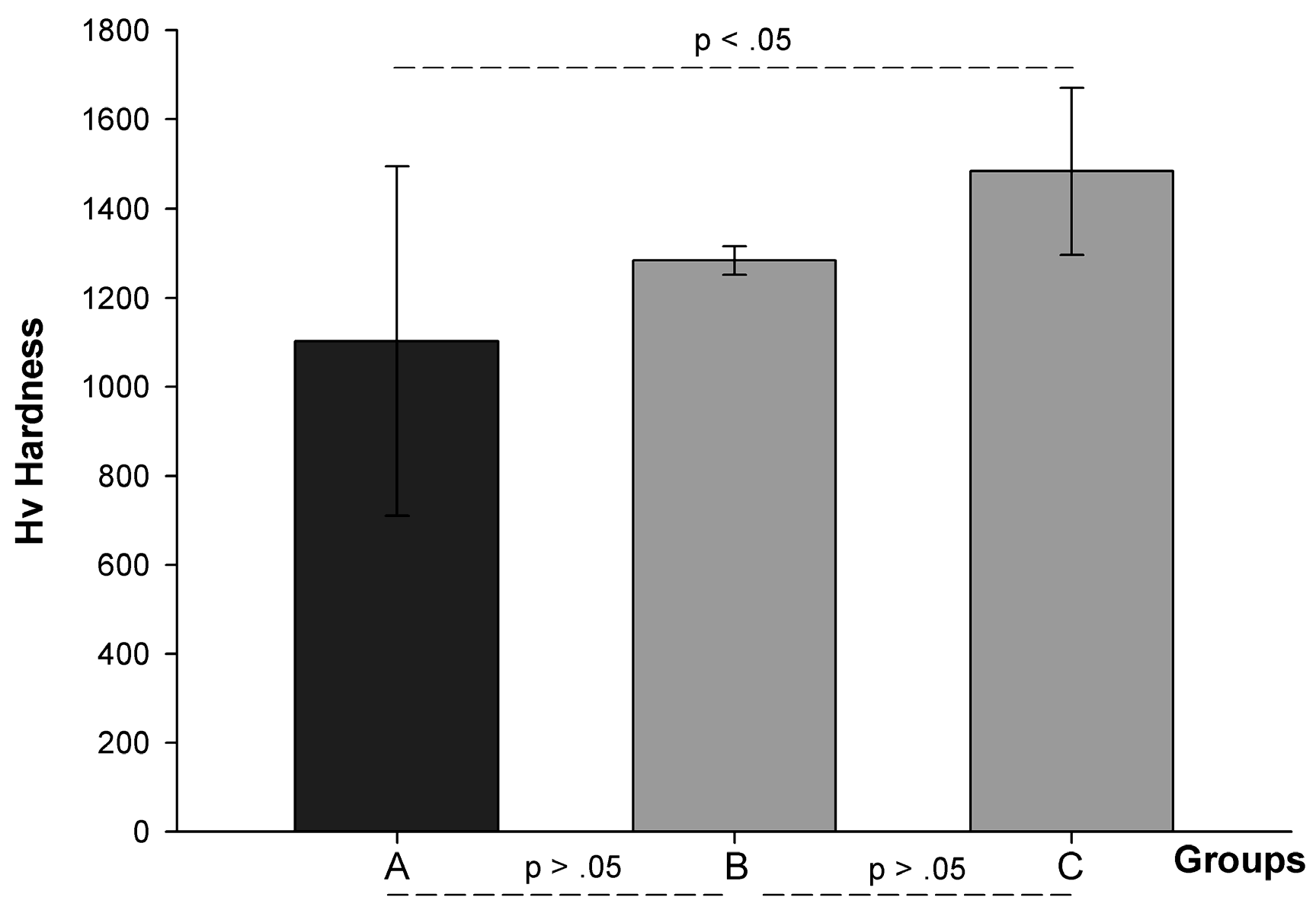
3.2. Vickers Hardness (Hv)

The Hv (mean ± SD) values for different groups were: 1102 ± 392 MPa for group A, 1284 ± 32 MPa for group B, and 1483 ± 187 for group C (Figure 4). The Hv was significantly increased in the group of “aged” zirconia (group C) samples compared to both group A and B (p = 0.002). Meanwhile, there was no statistically significant difference between group B and A (p > 0.05) (Figure 5).

3.3. Flexural Strength (Fs)

The results were: 427 (±59.5) MPa for group A; 805 (±198.4) MPa for group B and 440 (±96.2) MPa for group C. The Fs of traditional zirconia appeared significantly higher than the high-translucent zirconia (p = 0.004); however, no significant differences were shown in terms of Fs between the “aged”, which suffers aging, and group A (p > 0.05).

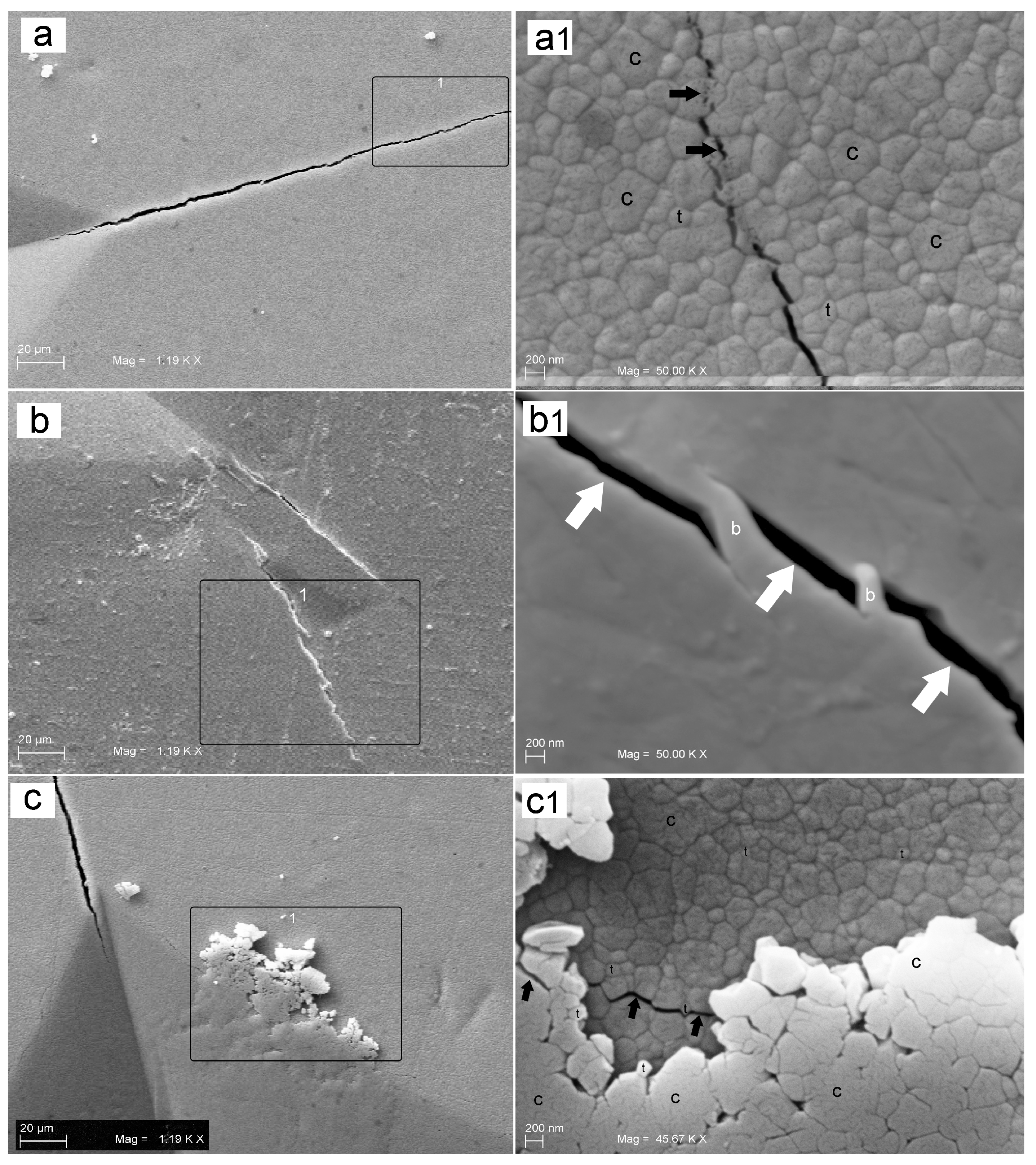
3.4. Fracture Toughness (Ft)

The results were: 4.9 (±0.9) MPa.m1/2 for group A; 8.9 (±1.1) MPa.m1/2 for group B and 5.1 (±0.7) MPa.m1/2 for group C. The Ft was significantly higher in group B compared to both group C and A (p < 0.001). Meanwhile, there were no statistically significant differences between group C and A. SEM images of microcracks and fractures are shown in in Figure 3 and Figure 6.

3.5. Brittleness (Br)

The Br values were: 230.9 (±46.4) for group A; 144.9 (±20.3) for group B and 295 (±42.8) for group C. The Br value was maximum in group C, whose entity was significantly higher (p < 0.001) compared to the other two groups (A and B). Group A had values immediately below, although significantly superior to group B. Using SEM analysis, it was possible to highlight the effects of the microcrack’s propagation, consisting in the formation of “bridging” along the margins of microcracks tending to close the fracture line itself as shown in Figure 6.
All data collected through mechanical tests are summarized in Table 2.

4. Discussion

The results demonstrated that the average grain size of the highly translucent zirconia particles was 165 ± 15 nm. It is reported that the reduction in the average grain size of zirconia ceramics has a positive effect on the stability [33,34,35,36,37] and, therefore, also on the LTD. Moreover, several studies have reported the ideal grain size of stabilized zirconia with 3% mol of yttria values that oscillates between 150 and 500 nm [33,38,39,40,41]. Sutharsini et al. showed that the average grain sizes of Y-TZP ceramics sintered at various holding times were between 0.24 and 0.26 µm [42]. On the other hand, the LTD process increases the Vickers hardness (Hv) of high-translucent zirconia and does not seem to alter either the flexural strength or the fracture toughness of high-translucent zirconia. In fact, in our study, Hv was significantly increased in the group of “aged” zirconia (group C) with a value of 1483 MPa, compared to both group A and B (p = 0.002) with 1102 MPa and 1284 MPa, respectively. These findings were in accordance with the data in the literature [43]. These results demonstrate how the aging process is capable of drastically increasing the Vickers hardness. Moreover, the brittleness of group C was significantly higher than the other two groups. The LTD process appeared to also increase the brittleness of high-translucent zirconia. In fact, the brittleness index values were 295 for group C, 230.9 for group A and 144.9 for group B. On the other hand, when we compared the crack path of translucent zirconia before and after aging, as reported in Figure 7a1,c1, the crack’s travel appeared to be different. The crack front in Figure 7a1 seemed to be locally deviated by the bigger grains that underwent intragranular fracture (black arrows). This behaviour creates a limit in crack speed. The propagating crack in Figure 7c1 appeared to run at grain boundaries level; this crack path drives a crack faster. Thus, a higher quality aesthetics may probably increase the fragility of the zirconia. The low-translucent zirconia reported in Figure 7b1 showed, at the crack-tip level, a crack deflection and crack shielding (bridging). This is a consequence of a great amount of energy stored. Furthermore, the presence of the “bridging” along the microcrack’s margins show the tendency of the low-translucent zirconia (group B) to strongly oppose the propagation of the fracture line. These observations were similar to the results obtained by Liu et al. [44].
While the flexural strength of group B appears significantly higher (p = 0.004) than the high-translucent zirconia (group A). These results can also be compared with other similar studies [45,46]. Flinn et al. stated that the LTD resulted in a significant decrease in flexural strength of Prettau [45,46]. Several studies [47,48,49] have investigated the ultra-translucent Prettau anterior zirconia. Some authors found no significant differences in strength after 8 h of steam autoclave treatment [48,49]. However, a significant reduction in strength was recorded in one study after ageing treatment [47]. In the present study, fracture toughness was significantly higher in group B than the other two groups (p < 0.001), although the values appeared high compared to the usual chewing loads. In addition, our results demonstrated that the macroscopic fracture can be influenced by the trend of microcrack. In fact, these were also evidenced by the SEM images at high magnification after three-point bending tests as shown in Figure 5. Several studies evaluating the clinical performance of ceramic/zirconia restorations have shown relatively high porcelain chipping and fracture rates in zirconia-ceramic restorations in posterior teeth [50]. Factors involved during the fabrication of the restorations include differences in the coefficient of thermal expansion, non-ideal heating or cooling rates between the substructure and the laminated porcelain, and the unfavourable cut between the zirconia structure and the ceramic coating [16,51,52,53,54]. The most frequent problems are the chipping of the ceramic or fracture of the structure; in most cases zirconia substructures rarely suffer damage and complications occur for the ceramic material [50,55,56]. Indeed, the study by Vigolo et al. [57] showed how the group of ceramic zirconia restorations was inclined to give more frequent clinical problems such as a fracture of the ceramic coating. For this reason, monolithic restorations have been recently introduced, specifically to reduce the incidence of chipping or fracturing of the glass ceramic veneer/component. These can be used without the porcelain coating, thus resulting in being directly exposed to the oral cavity. Even if the influence of sintering protocols onto the mechanical characteristics of the monolithic zirconia restorations was deeply investigated and reported [58,59,60,61,62], we do not consider it in the present study and used a standard procedure. In 2010, Jung et al. [63] analysed the effect of full zirconia restorations (Zirkonzahn Prettau) and feldspathic ceramics against dental enamel in a chewing simulator for 240,000 cycles. The author reported that the polished zirconia produced less abrasion than glazed zirconia or polished feldspathic ceramic. Recently, De Angelis et al. [64] reported a wear resistance for the ultra-translucent zirconia closest to that of type III gold alloy. On the other hand, Albashaireh et al. [65] showed how the degree of wear of the antagonist tooth enamel was significantly less in zirconia restorations compared to feldspar porcelain restorations. In conclusion, among various dental materials, the highly polished zirconia showed the lowest wear capacity against the antagonist enamel. Moreover, the glazed zirconia showed a superior wear capacity compared to highly polished zirconia, despite this surface is smooth before the test. This happens because the thin layer of glazing disappears from the areas of occlusal function after some time. [66]. Further studies must be performed on this topic.

5. Conclusions

The high-translucent zirconia, compared to the traditional one, showed a significant reduction in mechanical properties. The clinical applications should be related to the anterior/lateral area, where a high aesthetic performance is requested to the premolar region with relatively low occlusal stress.

Author Contributions

Conceptualization, T.T.; methodology, L.M. and T.T.; software, L.M. and T.T.; validation, L.M. and T.T.; formal analysis, L.M. and T.T.; investigation, T.T.; data curation, L.M. and T.T.; writing—original draft preparation, L.M. and T.T.; writing—review and editing, L.M. and T.T.; visualization, L.M. and T.T.; supervision T.T.; project administration, T.T.; funding acquisition, T.T. All authors have read and agreed to the published version of the manuscript.

Funding

This research was funded by Traini Tonino (T.T.) ex60% funds (TT60/2020).

Institutional Review Board Statement

Not applicable.

Informed Consent Statement

Not applicable.

Data Availability Statement

The data is unavailable.

Conflicts of Interest

The authors declare no conflict of interest.

References

  1. Pjetursson, B.E.; Sailer, I.; Zwahlen, M.; Hammerle, C.H. A systematic review of the survival and complication rates of all-ceramic and metal-ceramic reconstructions after an observation period of at least 3 years. Part I: Single crowns. Clin. Oral. Implant. Res. 2007, 18, 73–85. [Google Scholar] [CrossRef] [PubMed]
  2. Sailer, I.; Pjetursson, P.B.E.; Zwahlen, M.; Hammerle, C.H. A systematic review of the survival and complication rates of all-ceramic and metal-ceramic reconstructions after an observation period of at least 3 years. Part II: Fixed dental prostheses. Clin. Oral. Implant. Res. 2007, 18, 86–96. [Google Scholar] [CrossRef] [PubMed]
  3. Traini, T.; Sinjari, B.; Pascetta, R.; Serafini, N.; Perfetti, G.; Trisi, P.; Caputi, S. The zirconia-reinforced lithium silicate ceramic: Lights and shadows of a new material. Dent. Mater. J. 2016, 35, 748–755. [Google Scholar] [CrossRef] [PubMed] [Green Version]
  4. Traini, T.; Sorrentino, R.; Gherlone, E.; Perfetti, F.; Bollero, P.; Zarone, F. Fracture Strength of Zirconia and Alumina Ceramic Crowns Supported by Implants. J. Oral Implantol. 2015, 41, 352–359. [Google Scholar] [CrossRef] [Green Version]
  5. D’Addazio, G.; Santilli, M.; Rollo, M.L.; Cardelli, P.; Rexhepi, I.; Murmura, G.; Al-Haj Husain, N.; Sinjari, B.; Traini, T.; Özcan, M.; et al. Fracture Resistance of Zirconia-Reinforced Lithium Silicate Ceramic Crowns Cemented with Conventional or Adhesive Systems: An In Vitro Study. Materials 2020, 13, 2012. [Google Scholar] [CrossRef]
  6. Traini, T.; Gherlone, E.; Parabita, S.F.; Caputi, S.; Piattelli, A. Fracture toughness and hardness of a Y-TZP dental ceramic after mechanical surface treatments. Clin. Oral Investig. 2014, 18, 707–714. [Google Scholar] [CrossRef]
  7. Heuer, A.H.; Hobbs, L.W. Science, and Technology of Zirconia; The American Ceramic Society: Columbus, OH, USA, 1981; pp. 1–24. [Google Scholar]
  8. El-Ghany, O.S.; Sherief, A.H. Zirconia based ceramics, some clinical and biological aspects: Review. Future Dent. J. 2016, 2, 55–64. [Google Scholar] [CrossRef]
  9. Christel, P.; Meunier, A.; Heller, M.; Torre, J.P.; Peill, C.N. Mechanical properties and short-term in-vivo evaluation of yttrium-oxide partially stabilized zirconia. J. Biomed. Mater. Res. 1989, 23, 45–61. [Google Scholar] [CrossRef]
  10. Guazzato, M.; Albakry, M.; Ringer, S.P.; Swain, M.V. Strength, fracture tough- ness, and microstructure of a selection of all-ceramic materials. Part II. Zirconia-based dental ceramics. Dent. Mater. 2004, 20, 449–456. [Google Scholar] [CrossRef]
  11. Guazzato, M.; Albakry, M.; Swain, M.V.; Ironside, J. Mechanical properties of In-Ceram Alumina and In-Ceram Zirconia. Int. J. Prosthodont. 2002, 15, 339–346. [Google Scholar]
  12. Passerini, L. Isomorphism among oxides of different tetravalent metals: CeO 2—ThO 2; CeO 2—ZrO 2; CeO 2—HfO 2. Gazz. Chim. Ital. 1930, 60, 762–776. [Google Scholar]
  13. Ruff, O.; Ebert, F. Refractory ceramics: I. The forms of zirconium dioxide. Z. Anorg. Allg. Chem. 1929, 180, 19–41. [Google Scholar] [CrossRef]
  14. Denry, I.L.; Holloway, J.A. Microstructural and crystallographic surface changes after grinding zirconia-based dental ceramics. J. Biomed. Mater. Res. Part B Appl. Biomater. 2006, 76, 440–448. [Google Scholar] [CrossRef]
  15. Baldissara, P.; Llukacej, A.; Ciocca, L.; Valandro, F.L.; Scotti, R. Translucency of zirconia copings made with different CAD/CAM systems. J. Prosthet. Dent. 2010, 104, 6–12. [Google Scholar] [CrossRef]
  16. Gherlone, E.; Mandelli, F.; Capparè, P.; Pantaleo, G.; Traini, T.; Ferrini, F. A 3 years retrospective study of survival for zirconia-based single crowns fabricated from intraoral digital impressions. J. Dent. 2014, 42, 1151–1155. [Google Scholar] [CrossRef]
  17. Aurélio, I.L.; Marchionatti, A.M.; Montagner, A.F.; May, L.G.; Soares, F.Z. Does air particle abrasion affect the flexural strength and phase transformation of Y-TZP? A systematic review and meta-analysis. Dent. Mater. 2016, 32, 827–845. [Google Scholar] [CrossRef]
  18. Du, Q.; Swain, M.V.; Zhao, K. Fractographic analysis of anterior bilayered ceramic crowns that failed by veneer chipping. Quintessence Int. 2014, 45, 369–376. [Google Scholar]
  19. Chevalier, J. What is the future for zirconia as a biomaterial? Biomaterials 2006, 27, 535–543. [Google Scholar] [CrossRef]
  20. de Medeiros, R.A.; Vechiato-Filho, A.J.; Pellizzer, E.P.; Mazaro, J.V.; dos Santos, D.M.; Goiato, M.C. Analysis of the peri-implant soft tissues in contact with zirconia abutments: An evidence-based literature review. J. Contemp. Dent. Pract. 2013, 14, 567–572. [Google Scholar]
  21. Rimondini, L.; Cerroni, L.; Carrasi, A.; Torricelli, P. Bacterial colonization of zirconia ceramic surfaces: An in vitro and in vivo study. Int. J. Oral Maxillofac. Implant. 2002, 17, 793–797. [Google Scholar]
  22. Welander, M.; Abrahamsson, I.; Berglundh, T. The mucosal barrier at implant abutments of different materials. Clin. Oral Implant. Res. 2008, 19, 635–641. [Google Scholar]
  23. Jung, R.E.; Sailer, I.; Hämmerle, C.H.; Attin, T.; Schmidlin, P. In vitro color changes of soft tissues caused by restorative materials. Int. J. Periodontics Restor. Dent. 2007, 27, 251–257. [Google Scholar]
  24. Yoshimura, M.; Noma, T.; Kawabata, K.; Somiya, S. Role of water on the degradation process of Y-TZP. J. Mater. Sci. Lett. 1987, 6, 465–467. [Google Scholar] [CrossRef]
  25. Kobayashi, K.; Kuwajima, H.; Masaki, T. Phase change and mechanical properties of ZrO2-Y2O3 solid electrolyte after aging. Solid State Ion. 1981, 3, 489–495. [Google Scholar] [CrossRef]
  26. Alghazzawi, T.F.; Lemons, J.; Liu, P.R.; Essig, M.E.; Janowski, G.M. Evaluation of the optical properties of CAD-CAM generated yttria-stabilized zirconia and glassceramic laminate veneers. J. Prosthet. Dent. 2012, 107, 300–308. [Google Scholar] [CrossRef]
  27. Sakakibara, T.; Yoshihara, K.; Takeuchi, M.; Ban, S.; Kawai, T.; Murakami, H. Properties of dental polishing materials and devices. Jpn. Soc. Dent. Mater. Devices 2012, 31, 140. [Google Scholar]
  28. Ban, S. Caution for frame processing. In Current CAD/CAM Restoration; Practice in prosthodontics extra issue; Miura, H., Miyazaki, T., Eds.; Quintessence Publishing: Batavia, IL, USA, 2008; pp. 86–89. [Google Scholar]
  29. Harianawala, H.H.; Kheur, M.G.; Apte, S.K.; Kale, B.B.; Sethi, T.S.; Kheur, S.M. Comparative analysis of transmittance for different types of commercially available zirconia and lithium disilicate materials. J. Adv. Prosthodont. 2014, 6, 456–461. [Google Scholar] [CrossRef] [Green Version]
  30. Kontonasaki, E.; Rigos, A.E.; Ilia, C.; Istantsos, T. Monolithic Zirconia: An Update to Current Knowledge. Optical Properties, Wear, and Clinical Performance. Dent. J. 2019, 7, 90. [Google Scholar] [CrossRef]
  31. Sinjari, B.; D’Addazio, G.; Murmura, G.; Di Vincenzo, G.; Semenza, M.; Caputi, S.; Traini, T. Avoidance of Interaction between Impression Materials and Tooth Surface Treated for Immediate Dentin Sealing: An In Vitro Study. Materials 2019, 12, 3454. [Google Scholar] [CrossRef] [Green Version]
  32. Trunec, M. Effect of grain size on mechanical properties of 3Y-TZP ceramics. Ceram-Silik 2008, 52, 165–171. [Google Scholar]
  33. Lange, F.F.; Dunlpo, G.L.; Davis, B.I. Degradation during ageing of transformation toughened ZrO2–Y2O3 materials at 250 °C. J. Am. Ceram. Soc. 1986, 69, 237–240. [Google Scholar] [CrossRef]
  34. Garvie, R.C. The occurrence of metastable tetragonal zirconia as a crystallite size effect. J. Phys. Chem. 1965, 69, 1238–1243. [Google Scholar] [CrossRef]
  35. Garvie, R.C. Stabilization of the tetragonal structure in zirconia microcrystals. J. Phys. Chem. 1978, 82, 218–224. [Google Scholar] [CrossRef]
  36. Tsukuba, K.; Kubota, Y.; Tsukidate, T. Thermal and mechanical properties of Yttria -stabilized tetragonal zirconia polycrystals. In Advanced in Ceramics; American Ceramic Society, Inc.: Columbus, OH, USA, 1984; pp. 382–390. [Google Scholar]
  37. Munoz-Saldana, J.; Balmori-Ramirez, H.; Jaramillo-Vigueras, D.; Iga, T.; Schneider, G.A. Mechanical properties and low-temperature aging of tetragonal zirconia polycrystals processed by hot isostatic pressing. Mater. Res. 2003, 18, 2415–2426. [Google Scholar] [CrossRef]
  38. Lucas, T.J.; Lawson, N.C.; Janowski, G.M.; Burgess, J.O. Effect of grain size on the monoclinic transformation, hardness, roughness, and modulus of aged partially stabilized zirconia. Dent. Mater. 2015, 12, 1487–1492. [Google Scholar] [CrossRef]
  39. Matsui, K.; Yoshida, H.; Ikuhara, Y. Nanocrystalline, Ultra-Degradation-Resistant Zirconia: Its Grain Boundary Nanostructure and Nanochemistry. Sci. Rep. 2014, 4, 4758. [Google Scholar] [CrossRef] [Green Version]
  40. Kim, M.J.; Ahn, J.S.; Kim, J.H.; Kim, H.Y.; Kim, W.C. Effects of the sintering conditions of dental zirconia ceramics on the grain size and translucency. J. Adv. Prosthodont. 2013, 5, 161–166. [Google Scholar] [CrossRef] [Green Version]
  41. Gafur, M.; Sarker, M.; Alam, M.; Qadir, M. Effect of 3 mol% Yttria Stabilized Zirconia Addition on Structural and Mechanical Properties of Alumina-Zirconia Composites. Mater. Sci. Appl. 2017, 8, 584–602. [Google Scholar] [CrossRef] [Green Version]
  42. Sutharsini, U.; Thanihaichelvan, M.; Ting, C.H.; Ramesh, S.; Tan, C.Y.; Chandran, H.; Sarhan, A.A.D.; Ramesh, S.; Urriés, I. Effect of two-step sintering on the hydrothermal ageing resistance of tetragonal zirconia polycrystals. Ceram. Int. 2017, 43, 7594–7599. [Google Scholar] [CrossRef]
  43. Singh, R.; Meenaloshini, S.; Tan, C.; Sopyan, I.; Teng, W.D. Sintering and Ageing Properties of Manganese Doped Y-TZP Ceramics. In Proceedings of the 33rd International Conference & Exposition on Advanced Ceramics and Composites, Daytona Beach, FL, USA, 18–23 January 2009. [Google Scholar]
  44. Liu, C.; Eser, A.; Albrecht, T.; Stournari, V.; Felder, M.; Heintze, S.; Broeckmann, C. Strength characterization and lifetime prediction of dental ceramic materials. Dent. Mater. 2021, 37, 94–105. [Google Scholar] [CrossRef]
  45. Flinn, B.D.; Raigrodski, A.; Mancl, L.A.; Toivola, R.; Kuykendall, T. Influence of aging on flexural strength of translucent zirconia for monolithic restorations. J. Prosthet. Dent. 2017, 117, 303–309. [Google Scholar] [CrossRef] [PubMed]
  46. Kontonasaki, E.; Giasimakopoulos, P.; Rigos, A.E. Strength and aging resistance of monolithic zirconia: An update to current knowledge. Jpn. Dent. Sci. Rev. 2020, 56, 1–23. [Google Scholar] [CrossRef] [PubMed]
  47. Muñoz, E.M.; Longhini, D.; Antonio, S.G.; Adabo, G.L. The effects of mechanical and hydrothermal aging on microstructure and biaxial flexural strength of an anterior and a posterior monolithic zirconia. J. Dent. 2017, 63, 94–102. [Google Scholar] [CrossRef] [PubMed]
  48. Sulaiman, T.A.; Abdulmajeed, A.A.; Shahramian, K.; Lassila, L. Effect of different treatments on the flexural strength of fully versus partially stabilized monolithic zirconia. J. Prosthet. Dent. 2017, 118, 216–220. [Google Scholar] [CrossRef] [PubMed]
  49. Adabo, G.L.; Mariscal, E.M.; Hatanaka, G.R. Flexural strength and microstructure of anterior/monolithic zirconia after low-temperature aging. Dent. Mater. 2015, 31, e48–e49. [Google Scholar] [CrossRef]
  50. Sailer, I.; Gottnerb, J.; Kanelb, S.; Hammerle, C.H. Randomized controlled clinical trial of zirconia-ceramic and metal-ceramic posterior fixed dental prostheses: A 3-year follow-up. Int. J. Prosthodont. 2009, 22, 553–560. [Google Scholar]
  51. Komine, F.; Saito, A.; Kobayashi, K.; Koizuka, M.; Koizumi, H.; Matsumura, H. Effect of cooling rate on shear bond strength of veneering porcelain to a zirconia ceramic material. J. Oral Sci. 2010, 52, 647–652. [Google Scholar] [CrossRef] [Green Version]
  52. Aboushelib, M.N.; de Jager, N.; Kleverlaan, C.J.; Feilzer, A.J. Microtensile bond strength of different components of core veneered all-ceramic restorations. Dent. Mater. 2005, 21, 984–991. [Google Scholar] [CrossRef]
  53. Tan, J.P.; Sederstrom, D.; Polansky, J.R.; McLaren, E.A.; White, S.N. The use of slow heating and slow cooling regimens to strengthen porcelain fused to zirconia. J. Prosthet. Dent. 2012, 107, 163–169. [Google Scholar] [CrossRef]
  54. Komine, F.; Strub, J.R.; Matsumura, H. Bonding between layering materials and zirconia frameworks. Jpn. Dent. Sci. Rev. 2012, 48, 153–161. [Google Scholar] [CrossRef]
  55. Sailer, I.; Fehér, A.; Filser, F.; Gauckler, L.J.; Lüthy, H.; Hämmerle, C.H. Five-year clinical results of zirconia frameworks for posterior fixed partial dentures. Int. J. Prosthodont. 2007, 20, 383–388. [Google Scholar]
  56. Tang, X.; Nakamura, T.; Usami, H.; Wakabayashi, K.; Yatani, H. Effects of multiple firings on the mechanical properties and microstructure of veneering ceramics for zirconia frameworks. J. Dent. 2012, 40, 372–380. [Google Scholar] [CrossRef]
  57. Vigolo, P.; Mutinelli, S. Evaluation of zirconium-oxide-based ceramic single-unit posterior fixed dental prostheses (FDPs) generated with two CAD/CAM systems compared to porcelain-fused-to-metal single-unit posterior FDPs: A 5-year clinical prospective study. J. Prosthodont. 2012, 21, 265–269. [Google Scholar] [CrossRef]
  58. Kongkiatkamon, S.; Peampring, C. Effect of speed sintering on low temperature degradation and biaxial flexural strength of 5y-tzp zirconia. Molecules 2022, 27, 5272. [Google Scholar] [CrossRef]
  59. Ordoñez Balladares, A.; Abad-Coronel, C.; Ramos, J.C.; Martín Biedma, B.J. Fracture resistance of sintered monolithic zirconia dioxide in different thermal units. Materials 2022, 15, 2478. [Google Scholar] [CrossRef]
  60. Jerman, E.; Wiedenmann, F.; Eichberger, M.; Reichert, A.; Stawarczyk, B. Effect of high-speed sintering on the flexural strength of hydrothermal and thermo-mechanically aged zirconia materials. Dent. Mater. 2020, 36, 1144–1150. [Google Scholar] [CrossRef]
  61. Mayinger, F.; Pfefferle, R.; Reichert, A.; Stawarczyk, B. Impact of high-speed sintering of three-unit 3y-tzp and 4y-tzp fixed dental prostheses on fracture load with and without artificial aging. Int. J. Prosthodont. 2021, 34, 47–53. [Google Scholar] [CrossRef]
  62. Kongkiatkamon, S.; Peampring, C. Comparison of Regular and Speed Sintering on Low-Temperature Degradation and Fatigue Resistance of Translucent Zirconia Crowns for Implants: An In Vitro Study. J. Funct. Biomater. 2022, 13, 281. [Google Scholar] [CrossRef]
  63. Jung, Y.S.; Lee, J.W.; Choi, Y.J.; Ahn, J.S.; Shin, S.W.; Huh, J.B. A study on the invitro wear of the natural tooth structure by opposing zirconia or dental porcelain. J. Adv. Prosthodont. 2010, 2, 111–115. [Google Scholar] [CrossRef] [Green Version]
  64. De Angelis, F.; Buonvivere, M.; Sorrentino, E.; Rondoni, G.D.; D’Arcangelo, C. Wear Properties of Conventional and High-Translucent Zirconia-Based Materials. Materials 2022, 15, 7324. [Google Scholar] [CrossRef]
  65. Albashaireh, Z.S.M.; Ghazal, M.; Kern, M. Two-body wear of different ceramic materials opposed to zirconia ceramic. J. Prosthet. Dent. 2010, 104, 105–113. [Google Scholar] [CrossRef] [PubMed]
  66. Park, J.H.; Park, S.; Lee, K.; Yun, K.D.; Lim, H.P. Antagonist wear of three CAD/CAM anatomic contour zirconia ceramics. J. Prosthet. Dent. 2014, 111, 20–29. [Google Scholar] [CrossRef] [PubMed]
Figure 1. Image of the support realized for the execution of three-point bending tests, following the specifications suggested by ISO6872.
Prosthesis 05 00004 g001
Figure 2. SEM images showing the micrograins of Y-TZP Groups (50,000× magnification). (a) High-translucent zirconia; (b) low-translucent zirconia; (c) high-translucent zirconia after aging.
Prosthesis 05 00004 g002
Figure 3. Graphical representation of grain size distribution for groups A, B and C.
Prosthesis 05 00004 g003
Figure 4. SEM images of the Vickers indentations during the microhardness test. The dimension of the indentation determined the hardness, while the course and the length of the generated microcracks at the angles of the indentations were used to evaluate the fracture toughness. (a) High-translucent zirconia; (b) low-translucent zirconia; (c) high-translucent zirconia after aging.
Prosthesis 05 00004 g004
Figure 5. Graphical representation of Hv distribution for groups A, B and C.
Prosthesis 05 00004 g005
Figure 6. SEM images showing: (a) fracture and microcrack development at 193× magnification in group A. The surface area of the material involved by the four crack lines was 301 mm2; (a1) at higher magnification (1230×), the fracture propagation appears to involve the entire thickness of the specimen; (b) fracture and microcrack development at 552× magnification in group B. The surface area involved by the four crack lines was 23 mm2; (b1) at higher magnification (1190×), the fracture propagation appears to partially involve the specimen thickness.
Prosthesis 05 00004 g006
Figure 7. SEM images showing the microcrack propagation; (a) group A at low magnification (1190×). The rectangle delimits the area reported in a1; (a1) at higher magnification (50,000×), the relationship between grains and microcracks appears. The black arrows indicate a trans-granular fracture near the crack tip. It is also possible to recognize cubic grains (C) and tetragonal grains (t) on the basis of their dimensions. (b) Group B at low magnification (1190×). The rectangle delimits the area reported in (b1); (b1) at higher magnification (50,000×), the “bridging” phenomena (b) along the margins of microcracks (white arrows) highlight the effects that tend to close the fracture line, since the conventional zirconia undergoes a phase shift (tetragonal vs. monoclinic structure) with a crack tip closure phenomenon; (c) group C at low magnification (1190×). The rectangle delimits the area reported in (c1); (c1) at higher magnification (50,000×), a different relationship between grains and microcracks appears after the aging process. The black arrows indicate an intergranular fracture development (at grain boundaries) that shows a faster microcrack propagation. It is also possible to recognize cubic grains (C) and tetragonal grains (t) on the basis of their dimensions.
Prosthesis 05 00004 g007
Table 1. Composition in wt% of the materials.
Product NameZrO2
[wt%]
Y2O3
[wt%]
Fe2O3
[wt%]
SiO2
[wt%]
HfO2
[wt%]
Al2O3
[wt%]
Na2O
[wt%]
Prettau (group A)87–93<120.010.0200–10.04
Diazir * (group B)87–954–6001–50–10
* From Traini et al. [6].
Table 2. Summary of the data.
AverageGroup A (±SD)Group B (±SD)Group C (±SD)Measure Unit
Flexural Strength427 (±59.5)805 (±198.4)440 (±96.2)MPa
Fracture Toughness4.9 (±0.9)8.9 (±1.1)5.1 (±0.7)MPa.m1/2
Brittleness index230.9 (±46.4)144.9 (±20.3)295 (±42.8)Hv/MPa.m1/2
Vickers hardness1102 (±392)1284 (±32)1483 (±187)Hv
Grain Size2.7 (±1.2)0.16 (±0.05)3.0 (±1.1)µm2
Disclaimer/Publisher’s Note: The statements, opinions and data contained in all publications are solely those of the individual author(s) and contributor(s) and not of MDPI and/or the editor(s). MDPI and/or the editor(s) disclaim responsibility for any injury to people or property resulting from any ideas, methods, instructions or products referred to in the content.

