
Marginal and Internal Fit of Monolithic Zirconia Crowns Fabricated by Using Two Different CAD-CAM Workflows: An In Vitro Study

Abstract
:1. Introduction
2. Materials and Methods
3. Results
4. Discussion
5. Conclusions
Author Contributions
Funding
Institutional Review Board Statement
Informed Consent Statement
Data Availability Statement
Acknowledgments
Conflicts of Interest
References
- Blatz, M.B.; Conejo, J. The current state of chairside digital dentistry and materials. Dent. Clin. N. Am. 2019, 63, 175–197. [Google Scholar] [CrossRef] [PubMed]
- Abduo, J.; Elseyoufi, M. Accuracy of intraoral scanners: A systematic review of influencing factors. Eur. J. Prosthodont. Restor. Dent. 2018, 26, 101–121. [Google Scholar] [CrossRef] [PubMed]
- Mangano, F.; Gandolfi, A.; Luongo, G.; Logozzo, S. Intraoral scanners in dentistry: A review of the current literature. BMC Oral Health 2017, 17, 149. [Google Scholar] [CrossRef] [PubMed] [Green Version]
- Siqueira, R.; Galli, M.; Chen, Z.; Mendonça, G.; Meirelles, L.; Wang, H.L.; Chan, H.L. Intraoral scanning reduces procedure time and improves patient comfort in fixed prosthodontics and implant dentistry: A systematic review. Clin. Oral Investig. 2021, 25, 6517–6531. [Google Scholar] [CrossRef] [PubMed]
- Ammoun, R.; Suprono, M.S.; Goodacre, C.J.; Oyoyo, U.; Carrico, C.K.; Kattadiyil, M.T. Influence of tooth preparation design and scan angulations on the accuracy of two intraoral digital scanners: An in vitro study based on 3-dimensional comparisons. J. Prosthodont. 2020, 29, 201–206. [Google Scholar] [CrossRef] [PubMed]
- Leitão, C.I.M.B.; Fernandes, G.V.O.; Azevedo, L.P.P.; Araújo, F.M.; Donato, H.; Correia, A.R.M. Clinical performance of monolithic CAD/CAM tooth-supported zirconia restorations: Systematic review and meta-analysis. J. Prosthodont. Res. 2022, 66, 374–384. [Google Scholar] [CrossRef]
- de Kok, P.; Kleverlaan, C.J.; de Jager, N.; Kuijs, R.; Feilzer, A.J. Mechanical performance of implant-supported posterior crowns. J. Prosthet. Dent. 2015, 114, 59–66. [Google Scholar] [CrossRef]
- Nakamura, K.; Harada, A.; Inagaki, R.; Kanno, T.; Niwano, Y.; Milleding, P.; Örtengren, U. Fracture resistance of monolithic zirconia molar crowns with reduced thickness. Acta. Odontol. Scand. 2015, 73, 602–608. [Google Scholar] [CrossRef] [Green Version]
- Ramos, G.F.; Monteiro, E.B.; Bottino, M.A.; Zhang, Y.; Marques de Melo, R. Failure probability of three designs of zirconia crowns. Int. J. Periodontics Restor. Dent. 2015, 35, 843–849. [Google Scholar] [CrossRef] [Green Version]
- Sorrentino, R.; Triulzio, C.; Tricarico, M.G.; Bonadeo, G.; Gherlone, E.F.; Ferrari, M. In vitro analysis of the fracture resistance of CAD-CAM monolithic zirconia molar crowns with different occlusal thickness. J. Mech. Behav. Biomed. Mater. 2016, 61, 328–333. [Google Scholar] [CrossRef]
- Sulaiman, T.A.; Abdulmajeed, A.A.; Donovan, T.E.; Cooper, L.F.; Walter, R. Fracture rate of monolithic zirconia restorations up to 5 years: A dental laboratory survey. J. Prosthet. Dent. 2016, 116, 436–439. [Google Scholar] [CrossRef] [PubMed]
- Cionca, N.; Hashim, D.; Mombelli, A. Zirconia dental implants: Where are we now, and where are we heading? Periodontol. 2000 2017, 73, 241–258. [Google Scholar] [CrossRef] [PubMed]
- Griffin, J.D., Jr. Combining monolithic zirconia crowns, digital impressioning, and regenerative cement for a predictable restorative alternative to PFM. Compend. Contin. Educ. Dent. 2013, 34, 212–222. [Google Scholar] [PubMed]
- Mazza, L.C.; Lemos, C.A.A.; Pesqueira, A.A.; Pellizzer, E.P. Survival and complications of monolithic ceramic for tooth-supported fixed dental prostheses: A systematic review and meta-analysis. J. Prosthet. Dent. 2021, 128, 566–574. [Google Scholar] [CrossRef]
- Laumbacher, H.; Strasser, T.; Knüttel, H.; Rosentritt, M. Long-term clinical performance and complications of zirconia-based tooth- and implant-supported fixed prosthodontic restorations: A summary of systematic reviews. J. Dent. 2021, 111, 103723. [Google Scholar] [CrossRef]
- Abduo, J.; Lyons, K.; Swain, M. Fit of zirconia fixed partial denture: A systematic review. J. Oral Rehabil. 2010, 37, 866–876. [Google Scholar] [CrossRef]
- Hunter, A.J.; Hunter, A.R. Gingival margins for crowns: A review and discussion. Part II: Discrepancies and configurations. J. Prosthet. Dent. 1990, 64, 636–642. [Google Scholar] [CrossRef]
- Karlsson, S. The fit of Procera titanium crowns. An in vitro and clinical study. Acta. Odontol. Scand. 1993, 51, 129–134. [Google Scholar] [CrossRef]
- Contrepois, M.; Soenen, A.; Bartala, M.; Laviole, O. Marginal adaptation of ceramic crowns: A systematic review. J. Prosthet. Dent. 2013, 110, 447–454. [Google Scholar] [CrossRef]
- Boitelle, P.; Mawussi, B.; Tapie, L.; Fromentin, O. A systematic review of CAD/CAM fit restoration evaluations. J. Oral Rehabil. 2014, 41, 853–874. [Google Scholar] [CrossRef]
- Tuntiprawon, M.; Wilson, P.R. The effect of cement thickness on the fracture strength of all-ceramic crowns. Aust. Dent. J. 1995, 40, 17–21. [Google Scholar] [CrossRef] [PubMed]
- Wiskott, H.W.; Belser, U.C.; Scherrer, S.S. The effect of film thickness and surface texture on the resistance of cemented extracoronal restorations to lateral fatigue loading. Int. J. Prosthodont. 1999, 12, 255–262. [Google Scholar] [PubMed]
- May, L.G.; Kelly, J.R.; Bottino, M.A.; Hill, T. Effects of cement thickness and bonding on the failure loads of CAD/CAM ceramic crowns: Multi-physics FEA modeling and monotonic testing. Dent. Mater. 2012, 28, E99–E109. [Google Scholar] [CrossRef] [PubMed]
- Borba, M.; Cesar, P.F.; Griggs, J.A.; Della Bona, A. Adaptation of all-ceramic fixed partial dentures. Dent. Mater. 2011, 27, 1119–1126. [Google Scholar] [CrossRef] [PubMed] [Green Version]
- Holmes, J.R.; Bayne, S.C.; Holland, G.A.; Sulik, W.D. Considerations in measurement of marginal fit. J. Prosthet. Dent. 1989, 62, 405–408. [Google Scholar] [CrossRef]
- Holmes, J.R.; Sulik, W.D.; Holland, G.A.; Bayne, S.C. Marginal fit of castable ceramic crowns. J. Prosthet. Dent. 1992, 67, 594–599. [Google Scholar] [CrossRef]
- McLean, J.W.; von Frauenhofer, J.A. The estimation of cement film thickness by an in vivo technique. Br. Dent. J. 1971, 131, 107–111. [Google Scholar] [CrossRef]
- Sorensen, J.A. A standardized method for determination of crown margin fidelity. J. Prosthet. Dent. 1990, 64, 18–24. [Google Scholar] [CrossRef]
- Karataşli, O.; Kursoğlu, P.; Capa, N.; Kazazoğlu, E. Comparison of the marginal fit of different coping materials and designs produced by computer aided manufacturing systems. Dent. Mater. J. 2011, 30, 97–102. [Google Scholar] [CrossRef] [Green Version]
- Matta, R.E.; Schmitt, J.; Wichmann, M.; Holst, S. Circumferential fit assessment of CAD/CAM single crowns—A pilot investigation on a new virtual analytical protocol. Quintessence Int. 2012, 43, 801–809. [Google Scholar]
- Euán, R.; Figueras-Álvarez, O.; Cabratosa-Termes, J.; Oliver-Parra, R. Marginal adaptation of zirconium dioxide copings: Influence of the CAD/CAM system and the finish line design. J. Prosthet. Dent. 2014, 112, 155–162. [Google Scholar] [CrossRef] [PubMed]
- Souza, R.O.A.; Özcan, M.; Pavanelli, C.A.; Buso, L.; Lombardo, G.H.L.; Michida, S.M.A.; Mesquita, A.M. Marginal and internal discrepancies related to margin design of ceramic crowns fabricated by a CAD/CAM system. J. Prosthodont. 2012, 21, 94–100. [Google Scholar] [CrossRef] [PubMed]
- Kocaagaoglu, H.; Kilinc, H.I.; Albayrak, H. Effect of digital impressions and production protocols on the adaptation of zirconia copings. J. Prosthet. Dent. 2017, 117, 102–108. [Google Scholar] [CrossRef] [PubMed]
- Dauti, R.; Cvikl, B.; Franz, A.; Schwarze, U.Y.; Lilaj, B.; Rybaczek, T.; Moritz, A. Comparison of marginal fit of cemented zirconia copings manufactured after digital impression with Lava™ C.O.S and conventional impression technique. BMC Oral Health 2016, 16, 129. [Google Scholar] [CrossRef] [PubMed] [Green Version]
- Pedroche, L.O.; Bernardes, S.R.; Leão, M.P.; de Almeida Kintopp, C.C.; Correr, G.M.; Ornaghi, B.P.; Gonzaga, C.C. Marginal and internal fit of zirconia copings obtained using different digital scanning methods. Braz. Oral Res. 2016, 30, e113. [Google Scholar] [CrossRef] [Green Version]
- Rödiger, M.; Heinitz, A.; Bürgers, R.; Rinke, S. Fitting accuracy of zirconia single crowns produced via digital and conventional impressions-a clinical comparative study. Clin. Oral Investig. 2017, 21, 579–587. [Google Scholar] [CrossRef]
- Kohorst, P.; Brinkmann, H.; Dittmer, M.P.; Borchers, L.; Stiesch, M. Influence of the veneering process on the marginal fit of zirconia fixed dental prostheses. J. Oral Rehabil. 2010, 37, 283–291. [Google Scholar] [CrossRef]
- Pak, H.S.; Han, J.S.; Lee, J.B.; Kim, S.H.; Yang, J.H. Influence of porcelain veneering on the marginal fit of Digident and Lava CAD/CAM zirconia ceramic crowns. J. Adv. Prosthodont. 2010, 2, 33–38. [Google Scholar] [CrossRef] [Green Version]
- Torabi, K.; Vojdani, M.; Giti, R.; Taghva, M.; Pardis, S. The effect of various veneering techniques on the marginal fit of zirconia copings. J. Adv. Prosthodont. 2015, 7, 233–239. [Google Scholar] [CrossRef] [Green Version]
- Ahmed, W.M.; Abdallah, M.N.; McCullagh, A.P.; Wyatt, C.C.L.; Troczynski, T.; Carvalho, R.M. Marginal discrepancies of monolithic zirconia crowns: The influence of preparation designs and sintering techniques. J. Prosthodont. 2019, 28, 288–298. [Google Scholar] [CrossRef]
- Sakornwimon, N.; Leevailoj, C. Clinical marginal fit of zirconia crowns and patients’ preferences for impression techniques using intraoral digital scanner versus polyvinyl siloxane material. J. Prosthet. Dent. 2017, 118, 386–391. [Google Scholar] [CrossRef] [PubMed]
- Freire, Y.; Gonzalo, E.; Lopez-Suarez, C.; Pelaez, J.; Suarez, M.J. Evaluation of the marginal fit of monolithic crowns fabricated by direct and indirect digitization. J. Prosthodont. Res. 2021, 65, 291–297. [Google Scholar] [CrossRef] [PubMed]
- Rosenstiel, S.F.; Land, M.F.; Fujimoto, J. Contemporary Fixed Prosthodontics, 5th ed.; Elsevier: St. Louis, MO, USA, 2016; pp. 264–277. [Google Scholar]
- Tamac, E.; Toksavul, S.; Toman, M. Clinical marginal and internal adaptation of CAD/CAM milling, laser sintering, and cast metal ceramic crowns. J. Prosthet. Dent. 2014, 112, 909–913. [Google Scholar] [CrossRef] [PubMed]
- Kale, E.; Yilmaz, B.; Seker, E.; Özcelik, T.B. Effect of fabrication stages and cementation on the marginal fit of CAD-CAM monolithic zirconia crowns. J. Prosthet. Dent. 2017, 118, 736–741. [Google Scholar] [CrossRef] [PubMed]
- Sadeqi, H.A.; Baig, M.R.; Al-Shammari, M. Evaluation of marginal/internal fit and fracture load of monolithic zirconia and zirconia lithium silicate (ZLS) CAD/CAM crown systems. Materials 2021, 14, 6346. [Google Scholar] [CrossRef]
- Ha, S.J.; Cho, J.H. Comparison of the fit accuracy of zirconia-based prostheses generated by two CAD/CAM systems. J. Adv. Prosthodont. 2016, 8, 439–448. [Google Scholar] [CrossRef] [PubMed] [Green Version]
- Davis, S.H.; Kelly, J.R.; Campbell, S.D. Use of an elastomeric material to improve the occlusal seat and marginal seal of cast restorations. J. Prosthet. Dent. 1989, 62, 288–291. [Google Scholar] [CrossRef]
- Ferrairo, B.M.; Piras, F.F.; Lima, F.F.; Honório, H.M.; Duarte, M.A.H.; Borges, A.F.S.; Rubo, J.H. Comparison of marginal adaptation and internal fit of monolithic lithium disilicate crowns produced by 4 different CAD/CAM systems. Clin. Oral Investig. 2021, 25, 2029–2036. [Google Scholar] [CrossRef]
- Li, Y.; Zhao, J.; Sun, Z.; Lin, N.; Zheng, Y. Three-dimensional fit of self-glazed zirconia monolithic crowns fabricated by wet deposition. Dent. Mater. J. 2022, 41, 363–367. [Google Scholar] [CrossRef]
- Haddadi, Y.; Bahrami, G.; Isidor, F. Accuracy of crowns based on digital intraoral scanning compared to conventional impression-a split-mouth randomised clinical study. Clin. Oral Investig. 2019, 23, 4043–4050. [Google Scholar] [CrossRef]
- Uluc, I.G.; Guncu, M.B.; Aktas, G.; Turkyilmaz, I. Comparison of marginal and internal fit of 5-unit zirconia fixed dental prostheses fabricated with CAD/CAM technology using direct and indirect digital scans. J. Dent. Sci. 2022, 17, 63–69. [Google Scholar] [CrossRef] [PubMed]
- Schriwer, C.; Skjold, A.; Gjerdet, N.R.; Øilo, M. Monolithic zirconia dental crowns. Internal fit, margin quality, fracture mode and load at fracture. Dent. Mater. 2017, 33, 1012–1020. [Google Scholar] [CrossRef]
- Rau, S.A.; Raedel, M.; Mikeli, A.; Raedel, M.; Walter, M.H. Clinical fit of monolithic zirconia single crowns. Int. J. Prosthodont. 2018, 31, 443–445. [Google Scholar] [CrossRef] [PubMed]
- Paul, N.; Raghavendra Swamy, K.N.; Dhakshaini, M.R.; Sowmya, S.; Ravi, M.B. Marginal and internal fit evaluation of conventional metal-ceramic versus zirconia CAD/CAM crowns. J. Clin. Exp. Dent. 2020, 12, e31–e37. [Google Scholar] [CrossRef] [PubMed]
- Kale, E.; Seker, E.; Yilmaz, B.; Ozcelik, T.B. Effect of cement space on the marginal fit of CAD/CAM-fabricated monolithic zirconia crowns. J. Prosthet. Dent. 2016, 116, 890–895. [Google Scholar] [CrossRef] [PubMed]
- Yuzbasioglu, E.; Kurt, H.; Turunc, R.; Bilir, H. Comparison of digital and conventional impression techniques: Evaluation of patients’ perception, treatment comfort, effectiveness and clinical outcomes. BMC Oral Health 2014, 14, 10. [Google Scholar] [CrossRef] [Green Version]
- Schepke, U.; Meijer, H.J.; Kerdijk, W.; Cune, M.S. Digital versus analog complete-arch impressions for single-unit premolar implant crowns: Operating time and patient preference. J. Prosthet. Dent. 2015, 114, 403–406.e1. [Google Scholar] [CrossRef]
- Berrendero, S.; Salido, M.P.; Valverde, A.; Ferreiroa, A.; Pradíes, G. Influence of conventional and digital intraoral impressions on the fit of CAD/CAM-fabricated all-ceramic crowns. Clin. Oral Investig. 2016, 20, 2403–2410. [Google Scholar] [CrossRef]
- Anadioti, E.; Aquilino, S.A.; Gratton, D.G.; Holloway, J.A.; Denry, I.; Thomas, G.W.; Qian, F. 3D and 2D marginal fit of pressed and CAD/CAM lithium disilicate crowns made from digital and conventional impressions. J. Prosthodont. 2014, 23, 610–617. [Google Scholar] [CrossRef]
- Zimmermann, M.; Valcanaia, A.; Neiva, G.; Mehl, A.; Fasbinder, D. Digital evaluation of the fit of zirconia-reinforced lithium silicate crowns with a new three-dimensional approach. Quintessence Int. 2018, 49, 9–15. [Google Scholar] [CrossRef]
- Weaver, J.D.; Johnson, G.H.; Bales, D.J. Marginal adaptation of castable ceramic crowns. J. Prosthet. Dent. 1991, 66, 747–753. [Google Scholar] [CrossRef] [PubMed]


| Location | t | df | p-Value | Mean Difference | Std. E. | 95% CI Lower | 95% CI Upper |
|---|---|---|---|---|---|---|---|
| M | 3.793 | 18 | 0.001 * | 12.4 | 3.269 | 5.531 | 19.269 |
| AMA | 6.548 | 18 | 0.000 * | 18.9 | 2.886 | 12.836 | 24.964 |
| AOA | 4.844 | 10.738 | 0.001 * | 19.8 | 4.088 | 10.776 | 28.824 |
| O1 | 5.031 | 12.71 | 0.000 * | 27.7 | 5.506 | 15.777 | 39.623 |
| O2 | 7.044 | 11.874 | 0.000 * | 30.8 | 4.373 | 21.262 | 40.338 |
| O3 | 5.527 | 10.379 | 0.000 * | 35.4 | 6.405 | 21.199 | 49.601 |
| O4 | 4.360 | 18 | 0.000 * | 30.1 | 6.903 | 15.598 | 44.602 |
| O5 | 5.207 | 18 | 0.000 * | 24.4 | 4.686 | 14.556 | 34.244 |
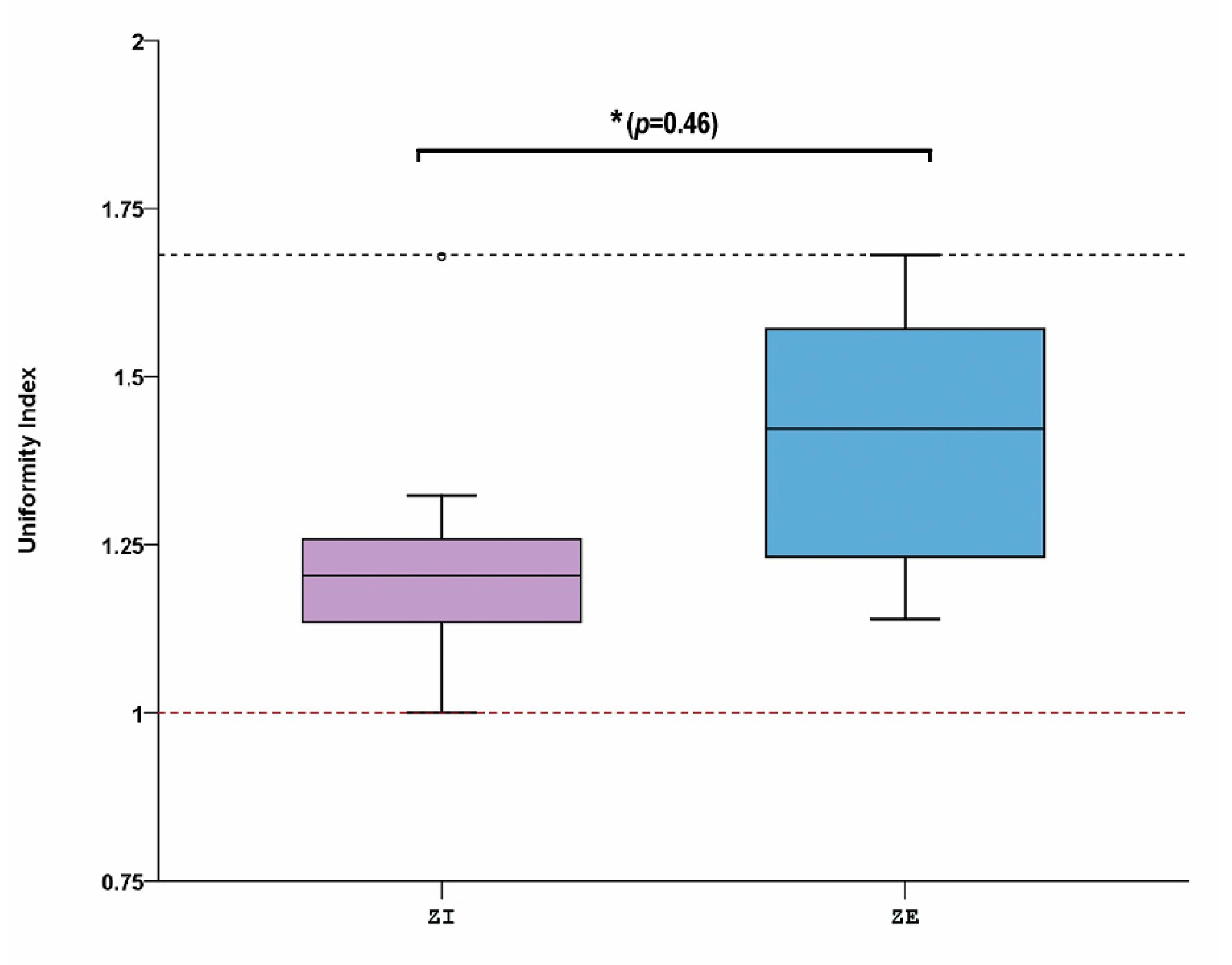
| Location | Group | Mean Rank | Sum of Ranks | U | p-Value |
|---|---|---|---|---|---|
| A | ZI | 6.35 | 63.50 | 8.5 | 0.002 * |
| ZE | 14.65 | 146.50 |
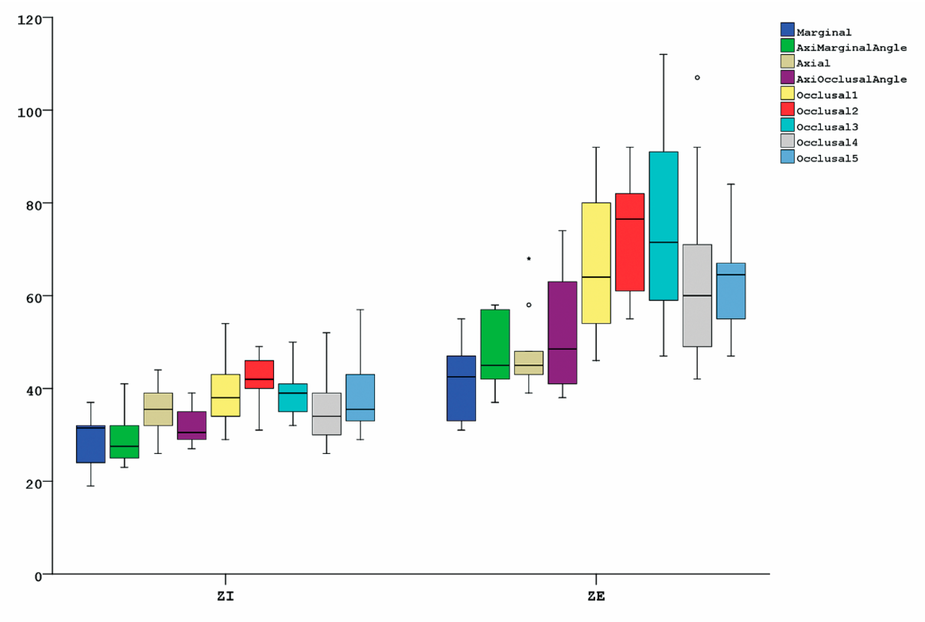
| Location | Group | Mean | Std. D. | Median | Std. E. | Min. | Max. |
|---|---|---|---|---|---|---|---|
| M | ZI | 29 | 6 | 32 | 2 | 19 | 37 |
| ZE | 42 | 9 | 43 | 3 | 31 | 55 | |
| AMA | ZI | 29 | 5 | 28 | 2 | 23 | 41 |
| ZE | 48 | 7 | 45 | 2 | 37 | 58 | |
| A | ZI | 36 | 5 | 36 | 2 | 26 | 44 |
| ZE | 47 | 9 | 45 | 3 | 39 | 68 | |
| AOA | ZI | 32 | 4 | 31 | 1 | 27 | 39 |
| ZE | 52 | 12 | 49 | 4 | 38 | 74 | |
| O1 | ZI | 39 | 7 | 38 | 2 | 29 | 54 |
| ZE | 66 | 16 | 64 | 5 | 46 | 92 | |
| O2 | ZI | 43 | 5 | 42 | 2 | 31 | 49 |
| ZE | 73 | 13 | 77 | 4 | 55 | 92 | |
| O3 | ZI | 39 | 5 | 39 | 2 | 32 | 50 |
| ZE | 75 | 20 | 72 | 6 | 47 | 112 | |
| O4 | ZI | 35 | 8 | 34 | 3 | 26 | 52 |
| ZE | 65 | 20 | 60 | 6 | 42 | 107 | |
| O5 | ZI | 39 | 9 | 36 | 3 | 29 | 57 |
| ZE | 64 | 12 | 65 | 4 | 47 | 84 |
| M | AMA | A | AOA | O1 | O2 | O3 | O4 | O5 | |
|---|---|---|---|---|---|---|---|---|---|
| #1 | 32 | 41 | 36 | 29 | 30 | 42 | 41 | 33 | 34 |
| (20–41) | (24–62) | (15–59) | (23–41) | (28;31) | (37;46) | (40;42) | (33;34) | (30;38) | |
| #2 | 30 | 30 | 35 | 27 | 36 | 46 | 38 | 36 | 39 |
| (20–41) | (19–38) | (17–59) | (21–37) | (30;42) | (34;58) | (33;44) | (35;37) | (39;40) | |
| #3 | 23 | 26 | 31 | 30 | 37 | 42 | 35 | 30 | 36 |
| (14–35) | (12–40) | (15–45) | (18–41) | (30;45) | (33;52) | (30;40) | (28;33) | (30;42) | |
| #4 | 19 | 25 | 26 | 31 | 42 | 46 | 50 | 45 | 53 |
| (10–40) | (5–42) | (16–52) | (22–40) | (37;46) | (43;49) | (46;53) | (36;54) | (53;54) | |
| #5 | 24 | 24 | 32 | 28 | 29 | 31 | 39 | 39 | 35 |
| (12–54) | (18–28) | (17–46) | (18–36) | (27;31) | (25;37) | (35;42) | (28;49) | (30;40) | |
| #6 | 32 | 32 | 39 | 36 | 43 | 48 | 39 | 35 | 43 |
| (20–45) | (15–40) | (19–70) | (33–41) | (30;56) | (33;64) | (28;49) | (30;40) | (40;46) | |
| #7 | 32 | 23 | 44 | 35 | 43 | 42 | 32 | 52 | 57 |
| (16–70) | (17–33) | (21–78) | (28–44) | (42;45) | (38;47) | (26;38) | (40;64) | (37;76) | |
| #8 | 37 | 32 | 39 | 39 | 54 | 49 | 46 | 26 | 33 |
| (17–66) | (14–44) | (13–61) | (27–50) | (49;58) | (40;59) | (44;49) | (26;26) | (31;35) | |
| #9 | 34 | 26 | 40 | 30 | 34 | 40 | 34 | 26 | 29 |
| (15–65) | (15–35) | (26–62) | (29–35) | (28;40) | (27;52) | (33;35) | (21;31) | (23;34) | |
| #10 | 31 | 29 | 33 | 33 | 39 | 40 | 39 | 31 | 33 |
| (17–47) | (20–37) | (21–40) | (27–38) | (35;43) | (38;43) | (35;42) | (29;33) | (31;34) |
| M | AMA | A | AOA | O1 | O2 | O3 | O4 | O5 | |
|---|---|---|---|---|---|---|---|---|---|
| #1 | 53 | 57 | 48 | 63 | 81 | 82 | 70 | 58 | 53 |
| (30–79) | (29–74) | (40–64) | (39–66) | (71;91) | (73;92) | (63;77) | (42;74) | (37;70) | |
| #2 | 32 | 42 | 46 | 41 | 49 | 55 | 47 | 49 | 47 |
| (14–46) | (23–61) | (33–64) | (27–57) | (43;56) | (44;67) | (37;58) | (44;53) | (45;49) | |
| #3 | 31 | 42 | 44 | 43 | 54 | 65 | 64 | 62 | 66 |
| (20–43) | (27–60) | (37–56) | (39–52) | (35;72) | (49;82) | (56;72) | (53;70) | (63;70) | |
| #4 | 45 | 45 | 39 | 56 | 92 | 89 | 81 | 66 | 67 |
| (30–60) | (26–60) | (22–60) | (40–74) | (88;96) | (75;103) | (65;96) | (53;78) | (52; 83) | |
| #5 | 33 | 37 | 39 | 44 | 61 | 78 | 73 | 49 | 55 |
| (21–52) | (25–50) | (23–56) | (37–57) | (60;63) | (70;86) | (65;80) | (37;60) | (42;68) | |
| #6 | 47 | 50 | 43 | 53 | 79 | 75 | 91 | 71 | 67 |
| (21–82) | (36–63) | (15–61) | (34–68) | (74;84) | (68;83) | (87;96) | (65;76) | (61;74) | |
| #7 | 46 | 57 | 43 | 38 | 55 | 61 | 58 | 42 | 55 |
| (24–85) | (32–85) | (33–64) | (32–42) | (46;64) | (52;70) | (52;65) | (37;47) | (52;58) | |
| #8 | 55 | 58 | 68 | 74 | 80 | 92 | 112 | 107 | 79 |
| (33–79) | (40–80) | (24–116) | (50–92) | (68;93) | (88;95) | (100;124 *) | (95;119) | (50;109) | |
| #9 | 40 | 45 | 58 | 64 | 67 | 78 | 92 | 92 | 84 |
| (21–61) | (29–59) | (30–84) | (38–82) | (64;70) | (75;82) | (82;102) | (75;110) | (70;98) | |
| #10 | 36 | 44 | 46 | 40 | 46 | 59 | 59 | 58 | 63 |
| (17–66) | (19–64) | (33–55) | (30–57) | (45;47) | (49;68) | (53;65) | (49;68) | (63;63) |
Disclaimer/Publisher’s Note: The statements, opinions and data contained in all publications are solely those of the individual author(s) and contributor(s) and not of MDPI and/or the editor(s). MDPI and/or the editor(s) disclaim responsibility for any injury to people or property resulting from any ideas, methods, instructions or products referred to in the content. |
© 2023 by the authors. Licensee MDPI, Basel, Switzerland. This article is an open access article distributed under the terms and conditions of the Creative Commons Attribution (CC BY) license (https://creativecommons.org/licenses/by/4.0/).
Share and Cite
Çin, V.; İzgi, A.D.; Kale, E.; Yilmaz, B. Marginal and Internal Fit of Monolithic Zirconia Crowns Fabricated by Using Two Different CAD-CAM Workflows: An In Vitro Study. Prosthesis 2023, 5, 35-47. https://doi.org/10.3390/prosthesis5010003
Çin V, İzgi AD, Kale E, Yilmaz B. Marginal and Internal Fit of Monolithic Zirconia Crowns Fabricated by Using Two Different CAD-CAM Workflows: An In Vitro Study. Prosthesis. 2023; 5(1):35-47. https://doi.org/10.3390/prosthesis5010003
Chicago/Turabian StyleÇin, Vahap, Ayça Deniz İzgi, Ediz Kale, and Burak Yilmaz. 2023. "Marginal and Internal Fit of Monolithic Zirconia Crowns Fabricated by Using Two Different CAD-CAM Workflows: An In Vitro Study" Prosthesis 5, no. 1: 35-47. https://doi.org/10.3390/prosthesis5010003