Article

Testing the Use of Advanced Upper Limb Prostheses: Towards Quantifying the Movement Quality with Inertial-Magnetic Measurement Units

by
Andreas W. Franzke
1,*,
Morten B. Kristoffersen
1,2,3,
Dario Farina
4,
Corry K. van der Sluis
1,
Raoul M. Bongers
5 and
Alessio Murgia
5
1
Department of Rehabilitation Medicine, University of Groningen, University Medical Center Groningen, 9713 GZ Groningen, The Netherlands
2
Center for Bionics and Pain Research, 431 30 Mölndal, Sweden
3
Department of Orthopaedics, Institute of Clinical Sciences, Sahlgrenska Academy, University of Gothenburg, 405 30 Gothenburg, Sweden
4
Department of Bioengineering, Faculty of Engineering, Imperial College London, London SW7 2AZ, UK
5
Department of Human Movement Sciences, University of Groningen, University Medical Center Groningen, 9713 GZ Groningen, The Netherlands
*
Author to whom correspondence should be addressed.
Prosthesis 2023, 5(1), 264-281; https://doi.org/10.3390/prosthesis5010020
Submission received: 28 December 2022 / Revised: 15 February 2023 / Accepted: 20 February 2023 / Published: 24 February 2023
(This article belongs to the Special Issue Design, Control, and Biomechanics of Prosthetic Limbs)

Abstract

:
Background: A thorough assessment of upper limb prostheses could help facilitate their transfer from scientific developments into the daily lives of users. Ideally, routine clinical testing would include assessments of upper limb function using motion-capturing technology. This is particularly relevant for the state-of-the-art upper limb prostheses. Methods: We designed a test based on an activity of daily life (“tray-task”) which could be completed outside the laboratory, and developed a set of outcome measures aimed at characterizing the movement quality. For this purpose, kinematics of the thorax and the humerus were captured with an inertial–magnetic measurement unit (IMMU) motion-capture system. Six prosthesis users and ten able-bodied participants were recruited to test the feasibility of the proposed assessment procedure and to evaluate the outcome variables. Results: All participants completed the test either at home or in our lab. The prosthesis users needed more time to complete the task and showed a larger range of motion in the thoracic flexion and a smaller range of motion in the humeral elevation, compared to the able-bodied participants. Furthermore, the prosthesis users’ movements were less smooth and characterized by less stable coordination patterns between the humerus and thorax. Conclusion: A new test method and associated outcome variables have been proposed.

1. Introduction

The scientific community has put much effort in advancing the functionality of upper limb prostheses, with advances in mechatronics and machine-learning control (see, e.g., [1,2,3,4]). Nonetheless, it is unclear to which degree prosthesis users benefit in their everyday lives from the technological advances demonstrated in research laboratories [5,6]. This might be related to the lack of appropriate assessment procedures for advanced prosthetic technologies [7]. Relevant clinical tests for the assessment of upper limb prostheses would better elucidate which system components need refinement and, therefore, would provide clear indications for technical developments.
A large number of well-designed and -established clinical assessment tools for upper limb prosthetics is available in the literature, such as the Southampton Hand Assessment Procedure (SHAP) [8,9], the Clothespin Relocation Test (CRT) [10,11,12], the Action Research Arm Test (ARAT) [13,14,15,16], the Box and Block Test (BBT) [17], the Activities Measure for Upper Limb Amputees (AM-ULA) [18], the Brief Activity Measure for Upper Limb Amputees (BAM-ULA) [19], the Assessment of capacity for myoelectric control (ACMC) [20,21], the Jebsen–Taylor Hand Function Test [22], the University of New Brunswick Test of Prosthetic Function (UNB) [23], and the timed measure of activity performance for persons with upper limb amputation (T-MAP) [24]. These tests focus on varying components (body function/activity and participation) related to the domains of the framework of the International Classification of Functioning, Disability, and Health (ICF) [25]. Additionally, all these tests are designed to be performed within the clinical routine. That means that neither extensive or complicated equipment nor highly technical or specialized personnel (with the exception of the ACMC, which requires a trained and certified observer) are required. These are clear advantages, or even necessities, for clinical tests. However, it also means that these tests are a compromise between the clinical feasibility and the depth of the assessment that could be achieved with more extensive methods, e.g., with motion-capture techniques and kinematic assessments. Indeed, the scientific community has used camera-based motion capturing to assess the upper limb function in prosthesis users during simulated activities of daily living (ADL) and reported movement deviations compared to able-bodied participants. These deviations include compensatory motion in several joints, such as in the trunk, the elbow, or the shoulder joint [26,27,28,29,30,31], decoupling of reaching-and-grasping, asymmetric velocity profiles, reduced smoothness and movement speed [32,33], higher kinematic variability in repeated task execution [29], and higher temporal variability in forearm acceleration [34]. For a review of an assessment of upper body kinematics during functional upper limb tasks, the reader can refer to [35].
An in-depth analysis of movement when using prostheses is particularly important with regard to the high prevalence of overuse complaints in prosthesis users, which are likely caused by unnatural movements and pathological compensation strategies when performing everyday tasks [36,37,38,39,40]. However, camera-based motion-capture assessments are unlikely to be routinely implemented in clinical tests because they require expensive and sophisticated equipment and personnel. Moreover, the setup and execution of camera-based motion capture is usually time-consuming, which is not always an option during clinical testing routine. Ideally, new test methods would combine the simplicity of the execution of standard clinical tests with the analytic depth and accuracy of motion-capture procedures. Furthermore, we argue that such new test methods should fulfill the following set of requirements:
(1) Given that the core purpose of a prosthetic device is to restore the potential to perform actions in everyday life, the functional user benefits of upper limb prostheses in solving everyday tasks need to be assessed on the activity and participation level within the framework of the International Classification of Functioning, Disability, and Health (ICF) [25], where the level of activity refers to “the execution of a task or action by an individual”. Testing the hand function at the level of body function in the framework of the ICF will yield little information about how the user solves the tasks in his/her everyday life and whether the prosthesis is actively involved [41,42].
(2) When testing upper limb prostheses in research settings, the test tasks and conditions should be chosen to reflect the way a prosthetic device is used in everyday life. In light of the evidence that upper limb prosthetics are predominantly used as a supporting and stabilizing tool in bimanual action, as opposed to unimanual object manipulation, the test tasks should require prosthesis use of both types [43,44].
(3) The test should aim at replicating the challenges which prosthesis users face outside of lab conditions. Lifting objects of different weights can put at risk the control robustness in myoelectric devices, specifically in machine-learning controlled multi-electrode systems. Likewise, the control can be affected by arm movements and a change in arm orientation [44,45,46]. Therefore, the test should require the user to move objects of different weights and to move their arm through various orientations.
(4) The outcomes of prosthesis assessments need to be sensitive to the potential advantages which state-of-the-art prostheses can offer. Multi-function upper limb prostheses and multi-electrode machine-learning-based control strategies aim at facilitating natural and dexterous movements, so the advantages of these systems should be expected (and assessed) at the level of the movement quality when solving tasks with the prosthesis.
In this study, we propose and test a new assessment procedure according to these requirements. In order to achieve an objective evaluation of the movement quality, we suggest using inertial–magnetic measurement unit (IMMU) motion-capture systems. These systems are easier to set up compared to opto-electronic systems and offer a high degree of portability. Moreover, since IMMU systems do not require the movement of the markers to be visible by mounted cameras, IMMU-based assessments are theoretically applicable to a wide variety of activities of daily living. Furthermore, we designed an exemplary ADL-task in line with the requirements of the new test methods, and we propose a set of outcome measures aiming at assessing the quality of the movements. To assess the feasibility of the test procedure, and to assess whether the outcome measures are sensitive to the deviations between prosthesis users and able-bodied individuals, two groups (six prosthesis users, ten able-bodied) completed the proposed test procedure.

2. Design of the Test Procedure—Methods

2.1. Participants

Six prosthesis users (mean age 50.2 ± 7.4 years, two females, see Table 1) and ten able-bodied participants (mean age 41.8 ± 19.8 years, four females) were recruited through invitation letters from their treating clinician (prosthesis users) and by word-of-mouth (able-bodied). All able-bodied individuals were right-handed, which was assessed with the handedness questionnaire of the Edinburgh Inventory, which is an established tool to assess the laterality of individuals [47,48]. Furthermore, all able-bodied were free of any movement restrictions or pathologies relating to the movements required to complete the task.

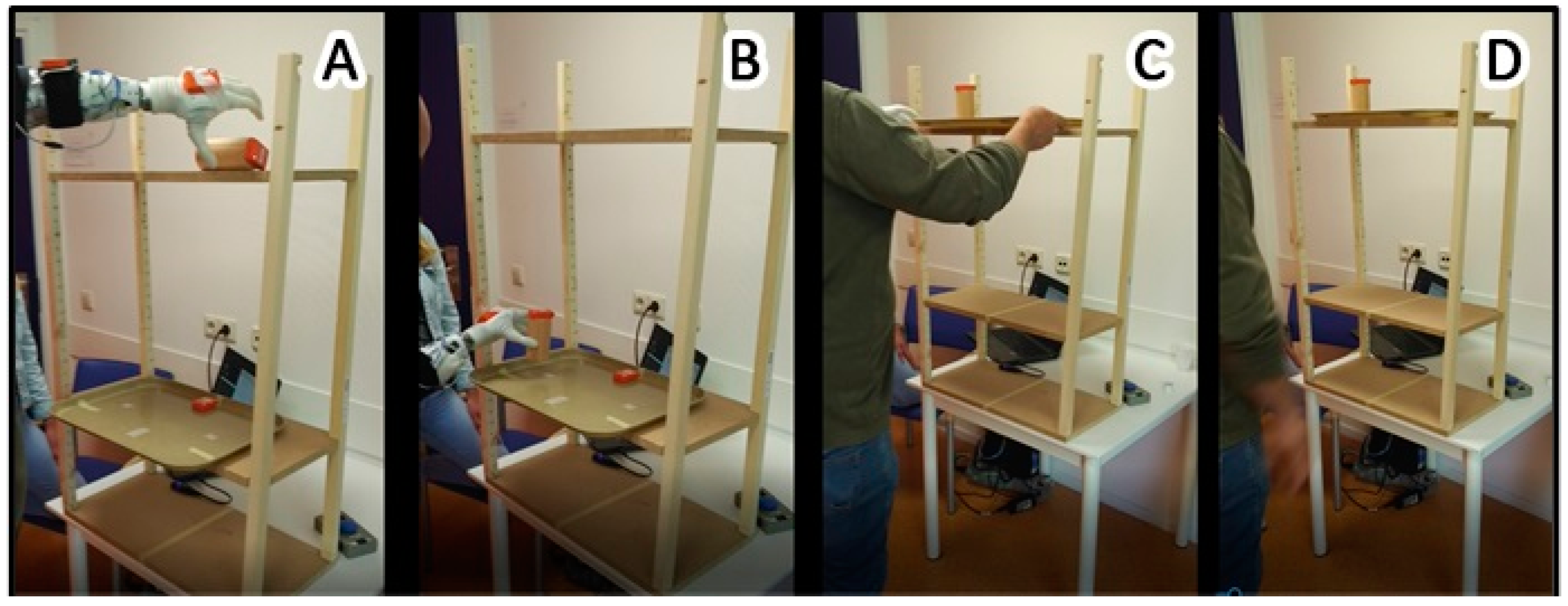
2.2. Description of the Task

We designed a tray-task’ according to the requirements formulated in the introduction section above. Namely, to execute the task the participants had to move the affected arm through a wide range of orientations, and the task required prehensile, as well as supporting actions of the prosthesis, in unimanual and bimanual upper limb movements. Moreover, the task required the user to lift objects of different weights.
The participants stood in front of a wooden rack (facing the rack), which had two height-adjustable shelves (Figure 1). The top shelf was placed at shoulder height, whereas the lower shelf was placed at 55% of the body height. For the able-bodied participants, the distance between the wooden rack and the participant was equal to the distance from the acromion to the styloid process of the radius with an extended elbow while reaching forwards. For the prosthesis users, the distance to the wooden rack was equal to the distance from the acromion to the “wrist” unit of the prosthesis.
A wooden cylinder was placed on the higher shelf, in a horizontal (laying) orientation. This cylinder was placed so that its edge was 20 cm away from the middle of the shelf, contra-lateral to the prosthesis side (for able-bodied individuals: contra-lateral to the non-dominant hand); see Figure 1A. This position required the participants to reach across their body at shoulder height and grab the cylinder with a palmar grip from the top; see Figure 1A.
A rectangular food-tray was placed in the middle of the lower shelf. The edge of the tray had approximately 5 cm overhang from the border of the wooden shelf to make it easier for the prosthesis users to grasp the edge of the tray; see Figure 1A,B.
In each repetition of the tray-task, the participants started in a neutral position, standing upright with both arms held downwards and parallel to the trunk. Then, the participants had to use their prosthesis (able-bodied individuals: non-dominant hand) to move the cylinder from the top shelf into a vertical standing position onto the food tray at the lower shelf; see Figure 1B. This part of the task required the participants to rotate the cylinder by 90 degrees and to lower it from approximately shoulder height to hip height.
Subsequently, the participants had to bimanually move the tray back to the top shelf, while the cylinder remained on the tray; see Figure 1C. After each repetition, the participant was instructed to remain in the neutral position for several seconds so that each repetition would be clearly distinguishable in the data. (See below: Data recording and analysis: Determination of onset and ending of one repetition). Furthermore, during this rest period, the experimenter moved the tray and the cylinder back to its initial position.
The participants were asked to perform the tray-task 15 consecutive times. However, during pilot tests, several prosthesis users reported uncomfortable muscle fatigue, predominantly in the shoulder, so the number of repetitions was set to 10 for prosthesis users to avoid fatigue effects on the performance.

2.3. Data Recording and Analysis

2.3.1. Placement of IMMUs

Two IMMUs (MVN Awinda, Xsens, Enschede, The Netherlands, sampling rate 60 Hz) were placed on the participant’s thorax (at the sternum) and on the humerus (laterally, in the middle between the humeral head and the lateral epicondyle). For the prosthesis users, the humeral IMMU was placed on the affected side, whereas for the able-bodied, the humeral sensor was placed on the non-dominant side. Furthermore, IMMUs were placed on the forearm and on the hand (prosthesis).
Initially, two more IMMUs were placed on the wooden cylinder and the tray to assist in the determination of the onset and the ending of one task repetition. However, these data were not used in this study.

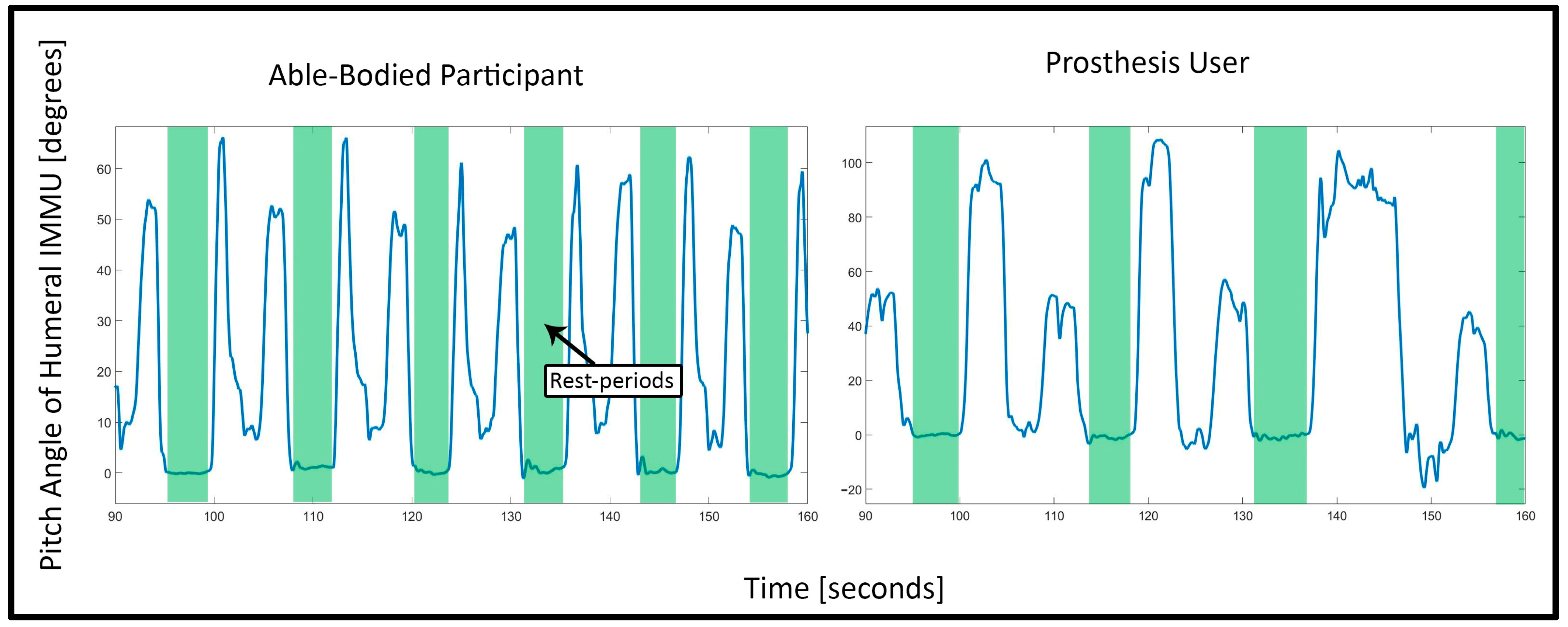
2.3.2. Determination of Onset and Ending of One Repetition

All data processing and visualization was performed in MATLAB (R2018a), Natick, Massachusetts: The MathWorks Inc. Visual inspection of the data revealed that the thorax and the humerus had the largest angular differences between able-bodied and prosthesis users, which was in agreement with previous findings; although, it should be noted that the type of compensation has been reported to be highly dependent on the task itself [26,27,49,50]. Therefore, we constrained the kinematic analysis to the thoracic and the humeral IMMU.
Onset and ending of one task repetition were then determined based on the angular data of the humeral IMMU axis which corresponded to humeral elevation, as we observed that the participants reliably initiated and finished the task by lifting and lowering their arm, respectively.
A threshold detection algorithm to automatically identify onset and ending of task repetitions proved successful for able-bodied data, but could not deal with the variability in postures and duration of the prosthesis users. Therefore, in order to avoid a potential bias between the two groups, the onset and ending were determined manually for all participants by marking the transitions from (and back to) the rest periods in the angular data of the humeral IMMU, as seen in Figure 2.

2.3.3. Calculation of 3D Orientation and Range of Motion

The 3D orientation of each sensor was expressed and stored in the form of rotation matrices by the IMMU system. For the purpose of visualization and interpretation of the data, we calculated Euler angles through Euler decomposition in custom-written MATLAB scripts, according to the recommendations of the International Society of Biomechanics (ISB) [51]. The orientation of the thorax segment was defined as the relative orientation of the thorax IMMU to the global coordinate system. The Euler angle decomposition order for the thorax sensor was Z-X′-Y″, where Z describes flexion/extension of the thorax around the transversal axis (i.e., forwards/backwards bending of the upper body), X′ describes lateral lean, and Y″ describes axial rotation [51]. Motion of the shoulder complex was defined as the relative orientation between the humeral IMMU and the thoracic IMMU (commonly referred to as a simplified “shoulder joint”). The corresponding Euler angle decomposition order was Y-X′-Y″, where Y describes the plane of elevation, X′ describes elevation, and Y″ describes internal and external rotation [51]. All Euler angles were reported in degrees. We limited the analysis to the axes in the thorax and the humerus where we expected the largest amplitude of movements to complete the tray-task: those were flexion/extension of the thorax around the transversal axis and humeral elevation. Range of motion was calculated as the difference between maximum and minimum angles per task repetition, averaged over all repetitions per participant.

2.3.4. Smoothness

For the purpose of assessing the smoothness of motion during the task execution, we calculated the change in acceleration over time (“jerk”) of the humeral IMMU.
The IMMU system outputs each sensor’s acceleration separately for each 3D axis without the gravity component, which is referred to as “free” acceleration. We then defined humeral jerk as:
H u m e r a l _ j e r k = ( a x ) ˙ 2 + ( a y ) ˙ 2 + ( a z ) ˙ 2
where a x ˙ , a y   ˙ , and a z ˙ are the first time-derivatives of the humeral IMMU’s “free” acceleration in the x-, y-, and z-axis, respectively. We based the definition of smoothness on the average peak prominence in the humeral jerk data. The prominence (also called “relative height”) is a metric derived from topography, and it quantifies the height of a peak relative to its surrounding data and, therefore, depicts the degree to which a peak “stands out” from the rest of the data. We defined smoothness based on the average prominence of all peaks per task repetition which exceeded a pre-defined threshold. This threshold (0.97 m/s3) was based on the able-bodied data and set as the mean of the humeral jerk per task repetition averaged over all able-bodied participants (mean = 0.39 m/s3), plus two times the standard deviation (std = 0.29 m/s3).

2.3.5. Stability of Coordination

For the purpose of assessing the stability of the coordination between the humeral and thoracic motion, we constructed angle–angle relative motion plots between humeral elevation and thoracic flexion [52]. In these plots, the time series of the angular data of one joint are plotted against the angular data of another joint. Therefore, these plots can reveal more information about the movement coordination than, e.g., the range of motion in both joints alone because the relative motion between two angles can be easily assessed. For example, if the lines of multiple task repetitions show a high congruency with respect to each other, it means that the participant showed a similar inter-segmental coordination during the task. In contrast, non-overlapping lines of several repetitions indicate that the participant showed a different movement pattern in each repetition with a more variable inter-segmental coordination. Furthermore, the trajectories can also reveal whether motion in one joint is leading/initiating the movement. Last, the smoothness of the trajectories in the angle–angle plots can also provide information about the fluidity of the movement.

2.3.6. Statistical Analysis

Due to the small number of participants in the prosthesis user group, for the statistical analyses no distinction was made between the users of a standard myoelectric device (n = 3) and those who used a multi-function upper limb prosthesis (n = 3), so that all prosthesis users were treated as one group. Potential differences between the users of different prosthesis types were taken up in the discussion section.
Before any statistical tests were performed, all data were averaged over task repetitions per person, so that each participant yielded one value per outcome. To assess the normality of each outcome variable, the Kolmogorov–Smirnov test was used to compare the distribution in each group to a standard normal distribution. Since the assumption of normality was violated for all variables, Wilcoxon rank sum tests were used to assess whether there was a statistically significant difference between the two groups. Effect sizes for the Wilcoxon rank sum test (r) were calculated as Z-statistic divided by the square root of the sample size. The significance level for all tests was set to 0.05. All statistical tests were conducted with R (v4.0.3) in RStudio (v1.3.1093).
Differences between the groups were assessed for the following outcomes: time-to-completion, range of motion in the shoulder elevation, range of motion in the thoracic flexion, and smoothness.

3. Results

All participants successfully completed the test. The testing of all able-bodied participants and three prosthesis users took place in the research laboratory. Two prosthesis users completed the test in the facility of their treating orthopedic technician, and one prosthesis user completed the test in his living room at home. The entire setup fit into two large suitcases, and two experimenters prepared the setup and guided the participants through the procedure. The whole preparation (setting up the wooden rack according to the participant’s measurements and attaching the IMMU sensors) took between 10–15 min per participant. The actual test procedure and recording of the data usually took less than 5 min per participant.

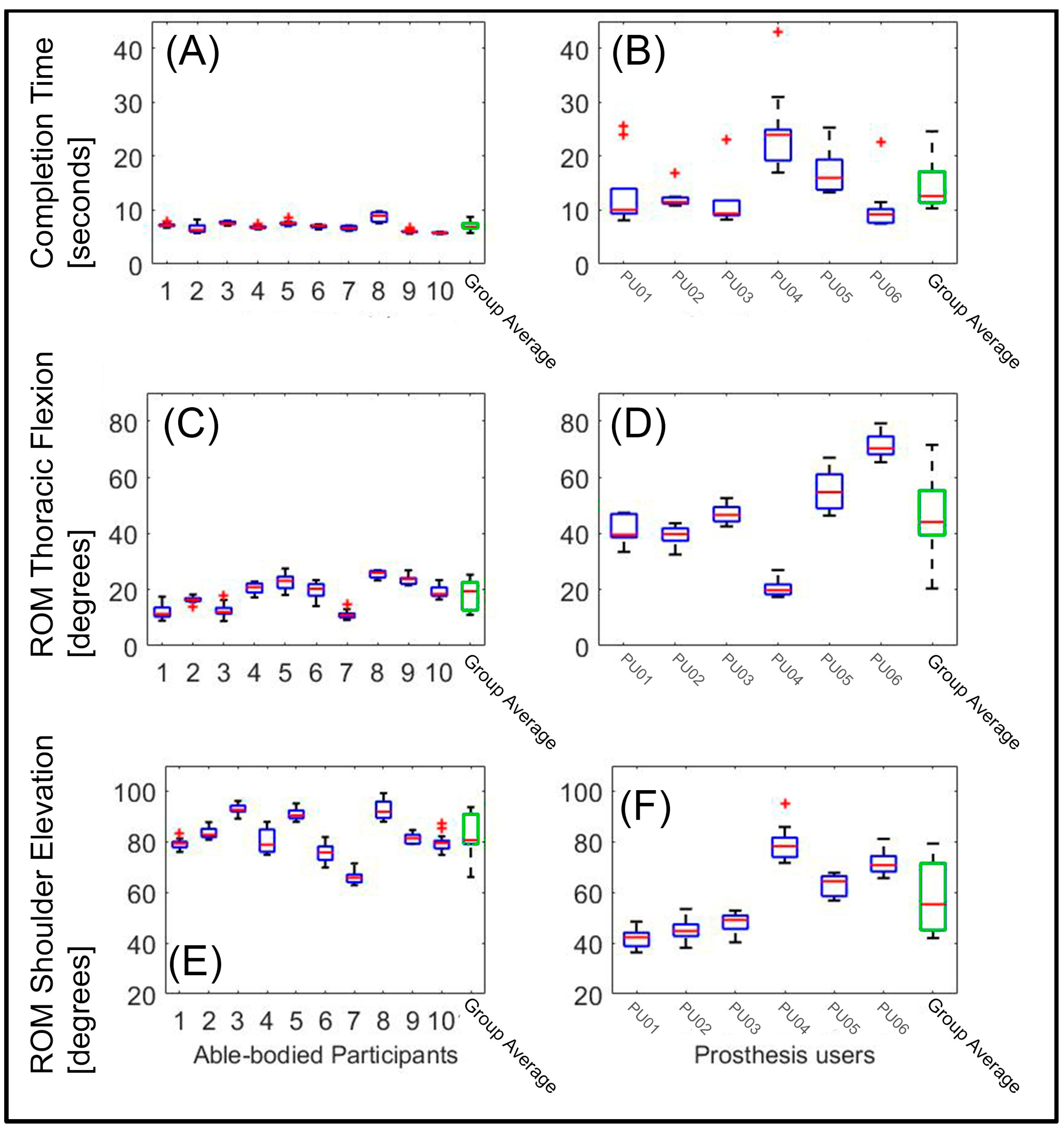
3.1. Average Time to Completion

The time to completion was longer for the prosthesis users (median (Mdn) = 12.6 s) than for the able-bodied participants (Mdn = 6.9 s), W = 55, p < 0.05, r = 0.81. Figure 3 shows the completion time for each participant and the average for both groups.

3.2. Range of Motion (ROM) in Body Angles: Thoracic Flexion (Anterior/Posterior) and Humeral Elevation

The ROM in the thoracic flexion was greater for the prosthesis users (Mdn = 44.05 degrees) than for the able-bodied participants (Mdn = 19.41 degrees), W = 59, p < 0.05, r = 0.71 (Figure 3, panels C and D). In contrast, the ROM in the shoulder elevation was smaller for the prosthesis users (Mdn = 55.36 degrees) than for the able-bodied participants (Mdn = 80.66 degrees), W = 111, p < 0.05, r = 0.71 (Figure 3, panels E and F). It appeared that the able-bodied participants completed the task predominantly by elevating their humerus, so as to pick up the cylinder from the upper shelf and to move the tray back to the higher shelf, with little movement of the thorax. The prosthesis users exploited both thoracic flexion and shoulder elevation.

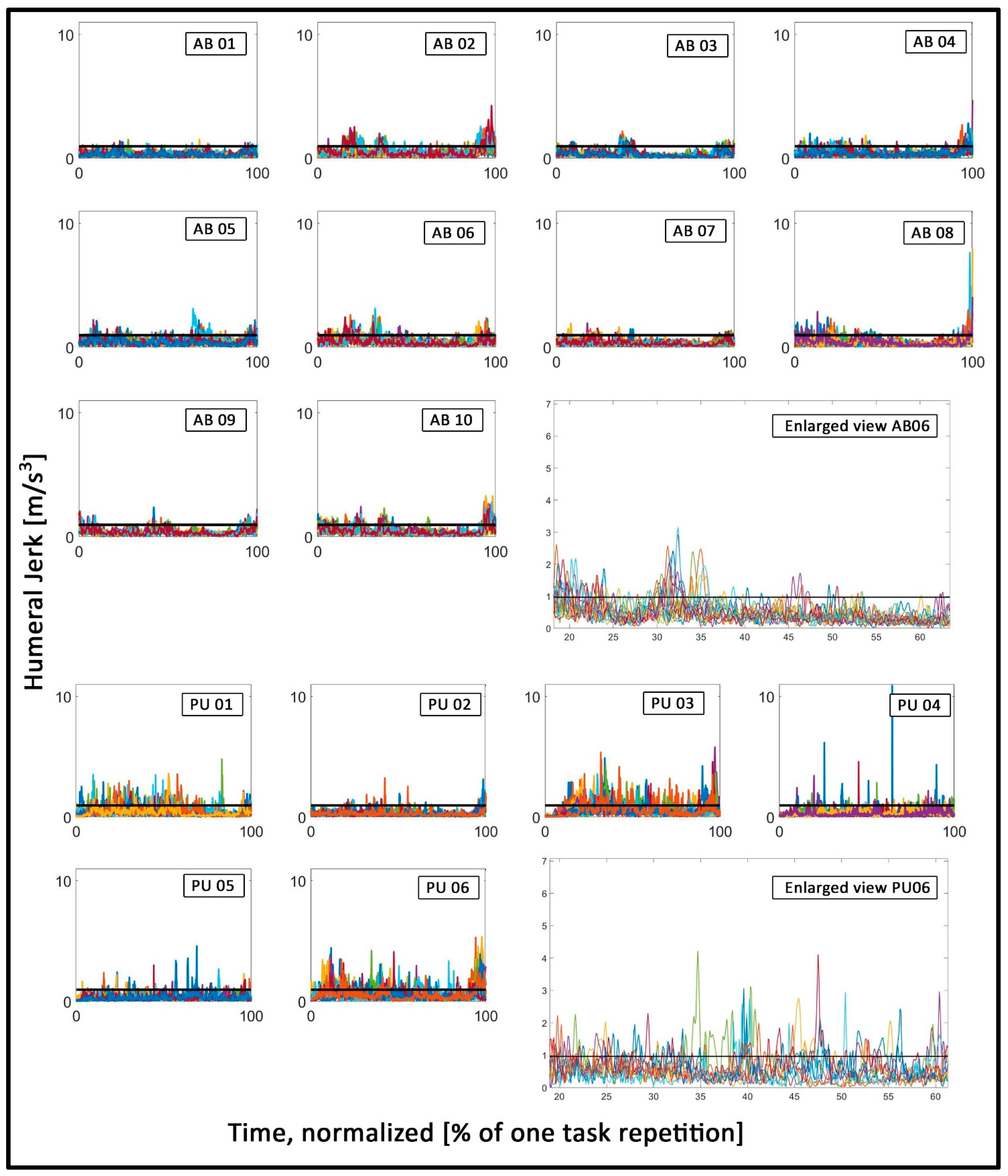
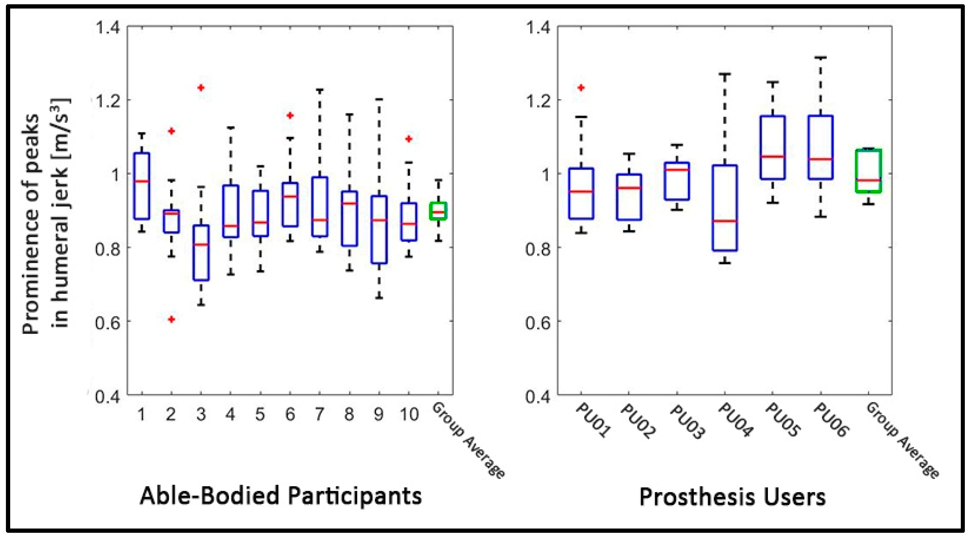
3.3. Smoothness of Motion: Prominence of Peaks in Humeral Jerk

The peak prominence was greater for the prosthesis users (Mdn = 0.98) than for the able-bodied participants (Mdn = 0.9), W = 60, p < 0.05, r = 0.68. This implies that the prosthesis users showed more abrupt changes in motion, depicted by larger peaks in the humeral jerk, compared to the able-bodied. Figure 4 shows the jerk data of the humeral IMMU of all individuals participants, with visibly prominent peaks in the prosthesis user data. Figure 5 shows the average prominence of the peaks which exceeded the defined threshold. It appears that there is a large variation between the prosthesis users, where some participants showed values similar to those of the able-bodied participants and others strongly exceeded those values.

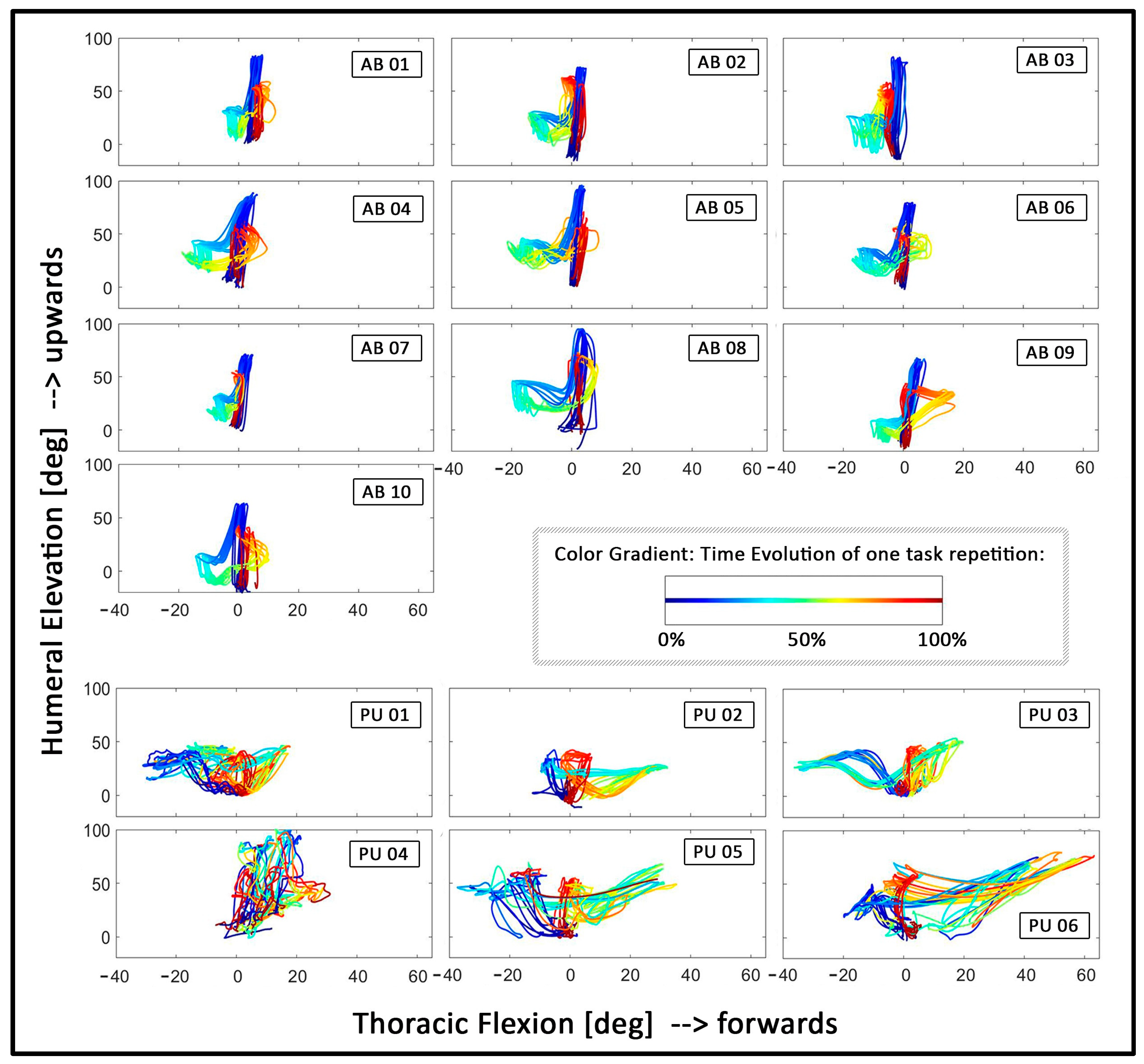
3.4. Coordination: Relative Motion between Thoracic Flexion and Humeral Elevation

From visual inspection of the angle–angle plots (see Figure 6), it can be derived that the able-bodied participants follow a similar coordinative strategy to complete the task, as the trajectories show a similar shape in each plot. All able-bodied individuals start by lifting their humerus to grasp the cylinder, followed by a small back and forth flexion of the thorax, followed by lowering of the humerus to put the cylinder onto the tray at hip height. Last, the tray with the cylinder is moved back to the top shelf, which is predominantly achieved by lifting the humerus again. Furthermore, the repetitions within each able-bodied participant appear highly consistent, indicated by the overlapping trajectories which follow a similar shape. In contrast, the group of the prosthesis users appears to show more variety between individuals, as each prosthesis user shows a unique shape of trajectories. Moreover, some prosthesis users appear to show repetitive trajectories, especially PU02 and PU03, whereas the remaining prosthesis users show little congruency between repetitions. Figure 6 shows the angle–angle plots between thoracic flexion and humeral elevation for all participants.

4. Discussion

Despite the impressive technological advancements demonstrated in prosthesis design, the daily-life benefits for prosthesis users have been slow to materialize [53,54]. This discrepancy reflects relatively long delays of transfer from the lab to the daily lives of the prosthesis users [5,6,46]. A possible contributing cause for this delay might be that the advancement of the assessment procedures has gained less attention than the advancement of the prosthetic technologies. This might affect the opportunities to exploit indications for improving the state-of-the-art prostheses towards higher functionality [5,55]. To advance the assessment paradigms, efforts should be made to replicate realistic outside-of-the-lab prosthesis use incorporating real-life challenges. Furthermore, the test outcome should aim at characterizing all relevant aspects of prosthesis use. In state-of-the-art upper limb prostheses, this includes the dexterity, the naturalness, or the quality of the moments [5,6,7,48].
In order to put the assessment of upper limb prosthetics forwards, we suggested a new assessment procedure which aims at finding a compromise between the simplicity of clinical tests for upper limb function and the analytic depth of motion-capture-based assessments. For that purpose, we restricted the measurement setup to a light-weight and portable system, so that the assessment could be carried out independently of the task and outside of the lab. We tested the feasibility of this assessment procedure by comparing the data of six (myoelectric) prosthesis users and ten able-bodied participants. All participants successfully completed the task, demonstrating the feasibility of the test in different environments (e.g., in the lab, clinic, or home environment). Furthermore, we found that the outcomes can discriminate between able-bodied individuals and prosthesis users.
The results showed that prosthesis users needed more time to complete the task and showed a larger ROM in thoracic flexion, compared to the able-bodied individuals, presumably to compensate for missing degrees-of-freedom in the upper limb [26,27,28,29,30,31,56]. The prosthesis users showed less humeral elevation compared to the able-bodied subjects, which was against our expectations [29,49]. The findings showed that the able-bodied participants mainly performed the task by primarily moving the arm, whereas prosthesis users exploited both trunk and arm movements. The prosthesis users might be aware that lifting the arm to a high angle might cause a shift of the socket and, therefore, cause control deterioration due to skin/electrode shifts [46]. Moreover, the large thoracic motion in the prosthesis users might also be a compensation strategy for the lack of DOFs in the prosthetic wrist. In particular, while placing the cylinder on the lower shelf and moving the tray back to the upper shelf, the prosthesis users relied strongly on movement of the thorax. (See, for example, Figure 1B, where the prosthesis user appears to be standing in a strongly forwards bend position.) Interestingly, the range-of-motion results of PU04 appear to stand out from the other prosthesis users. PU04 was the only user who had an active wrist rotation unit (pronation/supination), and he yielded a range of motion in both thoracic flexion and humeral elevation, which appeared more similar to the able-bodied individuals, compared to the other prosthesis users. Due to the number of participants, a statistical analysis of the effect of different prosthesis types was not possible; however, the results of PU04 might suggest that the access to more distal degrees of freedom in a prosthesis can reduce compensation motion in more proximal body joints, such as the thorax [49,57]. Although clearly preliminary, the data of this user might also imply that the test is able to discriminate the compensatory motions that result from different DOFs (not) being present. In future tests, measurements of the prosthetic movement itself (e.g., by reading out the motor commands of the prosthesis) in combination with IMMU-derived kinematic information would help in further assessing the association between the use of different prosthetic functions and the quality of the (human) movements.
Our results showed that relevant kinematic information can be captured with a highly mobile and easy-to-set-up IMMU system, which could be a first step towards implementing motion capturing into clinical testing routines. In addition, our results underlined the variability in joint angle coordination in prosthesis users depending on the task [10,26,28,29,58].
The prosthesis users’ movements furthermore appeared to be less smooth and interrupted by large changes in acceleration when compared to those of the able-bodied, as shown by the humeral IMMU jerk data (see Figure 5 and Figure 6) [32,33]. While smoothness is considered a hallmark of unimpaired movement (see, e.g., [59,60,61]), the most appropriate or clinical meaningful definition of smoothness is under discussion and might also be different between different populations, e.g., between individuals recovering from stroke and prosthesis users (see, e.g., [62,63]). We chose the prominence of the peaks in the jerk data because we observed that the prosthesis users’ data appeared to be characterized by large peaks which stood out from the surrounding data, while the able-bodied data showed no such “outstanding” peaks. In accordance with this observation, we found that simply calculating the average jerk showed no significant difference between the groups (data not shown). These findings appear to suggest that the prosthesis users’ movements are not necessarily less smooth “on average”, but rather, that if there are changes in the acceleration, they tend to be very sharp and large in magnitude, relative to the able-bodied individuals. It thus appeared that the prosthesis users needed to make strong and abrupt adjustments in their movements. These could be related to the unpredictability of the prosthesis response in myoelectric devices [32,64].
Lastly, the angle–angle plots between humeral and thoracic movement suggest that the coordination strategy of able-bodied participants was highly invariant, whereas prosthesis users exhibited more variable coordination patterns, which might be related to the high kinematic and temporal variability reported in prosthesis users [29,34]. These variable coordination patterns might be indicative of small and repetitive adaptations, which are needed to complete the tasks, e.g., due to unintended prosthesis motion [62]. Similarly, they could reflect a motor learning process, indicating that the prosthesis users were still learning how to complete the task optimally while adopting different strategies [29]. Assessing the stability of the performance, e.g., by quantifying the deviations between individual repetitions, might be useful for future assessments because such a metric could be related to the reliability of the control system [58,64].

4.1. Challenges in the Design of a New Assessment of Upper Limb Prosthetics

Currently, the only feasible way to assess the quality of movements, e.g., by quantifying compensatory movements, is to invite prosthesis users to the lab and record their kinematics (for a non-comprehensive list, see, e.g., [26,29,30,31,32,34,65,66,67,68,69,70], and for a review, see [35]). Given that the user (and thus, the clinics) are primarily interested in how well the user can accomplish motor tasks with the prosthesis under variable conditions during everyday life, e.g., at home or at work, it might be a fruitful next step to employ assessment procedures which could be completed in the users’ home environments and which are applicable to a large variety of activities [5,6].
We therefore provided a first attempt of designing an assessment in a way so that the test could be performed outside of the lab and task-independent. Thies et al. also developed a method to assess the upper limb temporal and amplitude variability in prosthesis users, and while the authors used camera-based data collection, their method would allow to collect the required data from IMMU sensors mounted to the participants’ arms and, therefore, presents a clinically feasible method which might be well-suited to combine with the measures presented in this study [34,71]. As a next step, we suggest to test these measures over a broad range of tasks in order to assess whether they indeed can be applied activity-independent. This would be an important step towards prosthesis assessments which move beyond standardized tasks and where users could ideally execute tasks of their own choice.
Furthermore, there is not a golden standard in evaluating movements with or without a prosthesis [72]. Thus, new outcome criteria need to be defined which can quantify the “naturalness” or the dexterity and thus provide clinically relevant information about the benefits of the prostheses, thereby closing the gap between the technological advancements and suitable clinical tests [7]. Recently, machine-learning methods applied to kinematic data have been proposed to further enhance the quantification of movement quality in prosthesis users [73]. Likewise, the importance and relation between different outcome measures need to be considered: For example, the prosthesis user PU04 (who used a device with wrist rotation) shows a range of thoracic flexion and shoulder elevation which is more in line with the able-bodied participants. This could be interpreted as a benefit of the prosthetic device. However, this user also shows seemingly “noisy” angle–angle plot trajectories without any clear coordinative strategy (Figure 6) and the highest completion time (Figure 3), which might be a negative consequence of the device used. In order to decide which outcomes are most meaningful, careful clinical consideration and a dialogue with the device users are crucial.

4.2. Limitations

The test procedure as described in this study cannot be an all-encompassing solution, and further steps need to be taken to refine the test procedures to eventually implement a new generation of prosthesis tests in clinical test routines [55]. The tray-task served as an exemplary task which aimed at fulfilling the requirements formulated in the introduction and was used in this study to assess whether the IMMU-derived measures would yield differences between the able-bodied participants and the prosthesis users.
We acknowledge that the weight that users had to lift and the range of arm orientations could have been larger to put more stress onto the prosthetic control systems. However, initial pilot tests revealed that some users found it difficult to lift the tray back to shoulder height and many users reported fatigue in the shoulder. Therefore, the procedure presented here was a compromise between applying stress to the control system and reducing the strain on the participants.
We also acknowledge that a larger group of prosthesis users would have strengthened the robustness of the study. However, we aimed at a relatively homogenous sample of prosthesis users (e.g., all myoelectric users), which further limited the range of potential participants.
Similarly, the assessment of coordination in angle–angle plots as performed in this study is expressed as a subjective measure. Future research should focus on a more effective and objective interpretation of these data, for instance, by expressing the stability of coordination patterns using appropriate dynamical system approaches [74]. Such methods are already implemented for the assessment of lower limb function (see, for example, [75,76,77,78]) and might further simplify the evaluation process. Recently, it has also been proposed to use the identification of inverse kinematic parameters in order to objectively quantify the inter-joint coordination in upper limb movements [79].
It is also noteworthy that despite the fact that we focused on myoelectric users only, there appear to be differences in the outcomes between the different type of prosthetic devices, although this is solely based on visual inspection of the data and not on statistical analyses. For example, users PU01, PU02, and PU03 seem to show less ROM in shoulder elevation, compared to the other three prosthesis users, who had a multi-function prosthesis (Figure 3). Relatedly, the angle–angle plots in Figure 6 appear to show more congruent/overlapping trajectories in PU01, PU02, and PU03, compared to the users of multi-function devices, which could indicate that the users of the simple one-degree-of-freedom prostheses rely on a somewhat more consistent coordinative strategy than those users who can switch the function (e.g., the grip type) of their prosthesis. Likewise, the prominence of the peaks in the jerk data appear to be lower in the users of one-degree-of-freedom prostheses (Figure 5) which could indicate that these users need to make less abrupt and less strong adjustments in their movements. Similarly, PU04, the only user with a device which allowed wrist rotation, appears to deviate from all other prosthesis users in nearly all outcomes (see Figure 3, Figure 4, Figure 5 and Figure 6). Whereas this might pose challenges to group-level analyses, it could also indicate that the IMMU-derived measures might be sensitive to device type. However, this clearly warrants further research given the small sample size.
Last, in the current design, a tester is still required to attach the IMMU sensors and to prepare the test setup. Ideally, in future iterations, smarter technology (e.g., embedded sensors in the prosthesis socket) might enable the prosthesis users to perform such a test in their home environments by themselves.

5. Conclusions

In summary, this study argues that functional assessment procedures should aim at replicating real-life prosthesis use, the assessment conditions should aim at reflecting real-life pitfalls of prosthesis use, and the assessment outcomes should aim at an evaluation of movement qualities that are expected to be affected by modern prosthetic systems, such as movement naturalness or dexterity.
We provide a first suggestion for a new assessment procedure to promote this shift of focus, by aiming at a compromise between the simplicity of clinical tests for upper limb function and the depth and accuracy of motion-capture-based assessments of upper limb function. Our results show that important kinematic parameters can be captured and the test could be performed in a relatively short time in different environments. We therefore conclude that the assessment procedure presented in this study might ultimately aid the refinement of prosthetic technologies and, therefore, aid the transfer process from research developments to the daily lives of prosthesis users.

Author Contributions

Conceptualization, A.W.F., M.B.K., D.F., C.K.v.d.S., R.M.B. and A.M.; data curation, A.W.F.; formal analysis, A.W.F.; investigation, A.W.F. and M.B.K.; methodology, A.W.F., M.B.K., C.K.v.d.S., R.M.B. and A.M.; software, A.W.F.; supervision, C.K.v.d.S., R.M.B. and A.M.; writing—original draft, A.W.F.; writing—review and editing, A.W.F., M.B.K., D.F., C.K.v.d.S., R.M.B. and A.M. All authors revised and edited the manuscript. All authors have read and agreed to the published version of the manuscript.

Funding

This research has received funding from the European Union’s Horizon 2020 research and innovation program under grant agreement number 687795 (Acronym: INPUT). The content of this manuscript does not reflect the official opinion of the European Union. Responsibility for the information and views expressed in the manuscript lies entirely with the authors. D.F.’s research is also sponsored by the Department of Bioengineering, Faculty of Engineering, Imperial College London, London, UK.

Institutional Review Board Statement

The ethics committee of the University Medical Center Groningen approved the study (METc 2018.268).

Informed Consent Statement

All participants gave written informed consent before participation.

Data Availability Statement

The datasets used and/or analyzed during the current study are available from the corresponding author on reasonable request.

Acknowledgments

The authors wish to thank Loë Kostermans and Annerens Hoogerkamp for their great assistance in the experimental sessions.

Conflicts of Interest

The authors declare no conflict of interest.

Abbreviations

ACMCAssessment of capacity for myoelectric control
ADLActivity of daily living
AM-ULAActivities Measure for Upper Limb Amputees
ARATThe Action Research Arm Test
BBTBox and Block Test
BAM-ULABrief Activity Measure for Upper Limb Amputees
CRTClothespin Relocation Test
ICFInternational Classification of Functioning Disability and Health
IMMUsInertial–magnetic measurement units
ISBInternational Society of Biomechanics
J-T HFTJebsen–Taylor Hand Function Test
ROMRange of motion
SHAPThe Southampton Hand Assessment Procedure
T-MAPtimed measure of activity performance for persons with upper limb amputation
UNBUniversity of New Brunswick Test of Prosthetic Function

References

  1. Atzori, M.; Muller, H. Control Capabilities of Myoelectric Robotic Prostheses by Hand Amputees: A Scientific Research and Market Overview. Front. Syst. Neurosci. 2015, 9, 162. Available online: http://www.ncbi.nlm.nih.gov/pubmed/26648850%5Cnhttp://www.ncbi.nlm.nih.gov/pmc/articles/PMC4663252/pdf/fnsys-09-00162.pdf (accessed on 5 February 2021). [CrossRef] [PubMed]
  2. Hudgins, B.; Parker, P.; Scott, R.N. A New Strategy for Multifunction Myoelectric Control. IEEE Trans. Biomed. Eng. 1993, 40, 82–94. [Google Scholar] [CrossRef] [PubMed]
  3. Belter, J.T.; Segil, J.L.; Dollar, A.M.; Weir, R.F. Mechanical Design and Performance Specifications of Anthropomorphic Prosthetic Hands: A Review. J. Rehabil. Res. Dev. 2013, 50, 599–618. Available online: http://www.ncbi.nlm.nih.gov/pubmed/24013909 (accessed on 5 February 2021). [CrossRef] [PubMed]
  4. Scheme, E.; Englehart, K. Electromyogram Pattern Recognition for Control of Powered Upper-Limb Prostheses: State of the Art and Challenges for Clinical Use. J. Rehabil. Res. Dev. 2011, 48, 643–660. Available online: http://www.rehab.research.va.gov/jour/11/486/pdf/scheme486.pdf (accessed on 5 February 2021). [CrossRef]
  5. Vujaklija, I.; Roche, A.D.; Hasenoehrl, T.; Sturma, A.; Amsuess, S.; Farina, D.; Aszmann, O.C. Translating research on myoelectric control into clinics-are the performance assessment methods adequate? Front Neurorobot. 2017, 11, 7. [Google Scholar] [CrossRef] [PubMed] [Green Version]
  6. Farina, D.; Aszmann, O. Bionic limbs: Clinical reality and academic promises. Sci. Transl. Med. 2014, 6, 257. [Google Scholar] [CrossRef]
  7. Hill, W.; Kyberd, P.; Norling Hermansson, L.; Hubbard, S.; Stavdahl, Ø.; Swanson, S. Upper Limb Prosthetic Outcome Measures (ULPOM): A Working Group and Their Findings. JPO J. Prosthet. Orthot. 2009, 21, P69–P82. [Google Scholar] [CrossRef]
  8. Light, C.M.; Chappell, P.H.; Kyberd, P.J. Establishing a standardized clinical assessment tool of pathologic and prosthetic hand function: Normative data, reliability, and validity. Arch. Phys. Med. Rehabil. 2002, 83, 776–783. [Google Scholar] [CrossRef] [Green Version]
  9. Burgerhof, J.G.M.; Vasluian, E.; Dijkstra, P.U.; Bongers, R.M.; van der Sluis, C.K. The Southampton Hand Assessment Procedure revisited: A transparent linear scoring system, applied to data of experienced prosthetic users. J. Hand. Ther. 2017, 30, 49–57. [Google Scholar] [CrossRef]
  10. Hussaini, A.; Kyberd, P. Refined clothespin relocation test and assessment of motion. Prosthet. Orthot. Int. 2017, 41, 294–302. [Google Scholar] [CrossRef]
  11. Kyberd, P.; Hussaini, A.; Maillet, G. Characterisation of the Clothespin Relocation Test as a functional assessment tool. J. Rehabil. Assist. Technol. Eng. 2018, 5, 2055668317750810. [Google Scholar] [CrossRef] [PubMed] [Green Version]
  12. Hussaini, A.; Hill, W.; Kyberd, P. Clinical evaluation of the refined clothespin relocation test: A pilot study. Prosthet. Orthot. Int. 2019, 43, 485–491. [Google Scholar] [CrossRef] [PubMed] [Green Version]
  13. Carroll, D. A quantitative test of upper extremity function. J. Chronic Dis. 1965, 18, 479–491. [Google Scholar] [CrossRef] [Green Version]
  14. Lyle, R.C. A performance test for assessment of upper limb function in physical rehabilitation treatment and research. Int. J. Rehabil. Res. 1981, 4, 483–492. [Google Scholar] [CrossRef] [PubMed]
  15. van der Lee, J.H.; Roorda, L.D.; Beckerman, H.; Lankhorst, G.J.; Bouter, L.M. Improving the Action Research Arm test: A unidimensional hierarchical scale. Clin. Rehabil. 2002, 16, 646–653. [Google Scholar] [CrossRef] [Green Version]
  16. Yozbatiran, N.; Der-Yeghiaian, L.; Cramer, S.C. A standardized approach to performing the action research arm test. Neurorehabil. Neural. Repair 2008, 22, 78–90. [Google Scholar] [CrossRef] [Green Version]
  17. Mathiowetz, V.; Volland, G.; Kashman, N.; Weber, K. Adult norms for the Box and Block Test of manual dexterity. Am. J. Occup. Ther. 1985, 39, 386–391. [Google Scholar] [CrossRef] [Green Version]
  18. Resnik, L.; Adams, L.; Borgia, M.; Delikat, J.; Disla, R.; Ebner, C.; Walters, L.S. Development and evaluation of the activities measure for upper limb amputees. Arch. Phys. Med Rehabil. 2013, 94, 488–494. [Google Scholar] [CrossRef]
  19. Resnik, L.; Borgia, M.; Acluche, F. Brief activity performance measure for upper limb amputees: BAM-ULA. Prosthet. Orthot. Int. 2018, 42, 75–83. [Google Scholar] [CrossRef] [Green Version]
  20. Hermansson, L.M.; Fisher, A.G.; Bernspang, B.; Eliasson, A.-C. Assessment of capacity for myoelectric control: A new Rasch-built measure of prosthetic hand control. J. Rehabil. Med. 2005, 37, 166–171. [Google Scholar] [CrossRef] [Green Version]
  21. Hermansson, L.M.; Bodin, L.; Eliasson, A.-C. Intra- and inter-rater reliability of the assessment of capacity for myoelectric control. J. Rehabil. Med. 2006, 38, 118–123. [Google Scholar] [CrossRef] [Green Version]
  22. Jebsen, R.H.; Taylor, N.; Trieschmann, R.B.; Trotter, M.J.; Howard, L.A. An objective and standardized test of hand function. Arch. Phys. Med. Rehabil. 1969, 50, 311–319. [Google Scholar] [PubMed]
  23. Sanderson, E.R.; Scott, R.N. UNB Test of Prosthetics Function: A Test for Unilateral Upper Extremity Amputees, Ages 2–13; Institute of Biomedical Engineering, University of New Brunswick: Fredericton, NB, Canada, 1985. [Google Scholar]
  24. Resnik, L.; Borgia, M.; Acluche, F. Timed activity performance in persons with upper limb amputation: A preliminary study. J. Hand Ther. 2017, 30, 468–476. [Google Scholar] [CrossRef] [PubMed]
  25. WHO. The International Classification of Functioning, Disability and Health; World Health Organization: Geneva, Switzerland, 2001; Volume 18, p. 237. [Google Scholar]
  26. Carey, S.L.; Jason Highsmith, M.; Maitland, M.E.; Dubey, R.V. Compensatory movements of transradial prosthesis users during common tasks. Clin. Biomech. 2008, 23, 1128–1135. [Google Scholar] [CrossRef] [PubMed]
  27. Carey, S.L.; Dubey, R.V.; Bauer, G.S.; Highsmith, M.J. Kinematic comparison of myoelectric and body powered prostheses while performing common activities. Prosthet. Orthot. Int. 2009, 33, 179–186. [Google Scholar] [CrossRef]
  28. Hebert, J.S.; Lewicke, J. Case report of modified Box and Blocks test with motion capture to measure prosthetic function. J. Rehabil. Res. Dev. 2012, 49, 1163–1174. [Google Scholar] [CrossRef]
  29. Major, M.J.; Stine, R.L.; Heckathorne, C.W.; Fatone, S.; Gard, S.A. Comparison of range-of-motion and variability in upper body movements between transradial prosthesis users and able-bodied controls when executing goal-oriented tasks. J. Neuroeng. Rehabil. 2014, 11, 132. [Google Scholar] [CrossRef] [Green Version]
  30. Hebert, J.S.; Boser, Q.A.; Valevicius, A.M.; Tanikawa, H.; Lavoie, E.B.; Vette, A.H.; Pilarski, P.M.; Chapman, C.S. Quantitative Eye Gaze and Movement Differences in Visuomotor Adaptations to Varying Task Demands Among Upper-Extremity Prosthesis Users. JAMA Netw. Open 2019, 2, e1911197. [Google Scholar] [CrossRef] [Green Version]
  31. Valevicius, A.M.; Boser, Q.A.; Chapman, C.S.; Pilarski, P.M.; Vette, A.H.; Hebert, J.S. Compensatory strategies of body-powered prosthesis users reveal primary reliance on trunk motion and relation to skill level. Clin. Biomech. 2019, 21, 74–78. [Google Scholar] [CrossRef]
  32. Bouwsema, H.; der Sluis CK van Bongers, R.M. Movement characteristics of upper extremity prostheses during basic goal-directed tasks. Clin. Biomech. 2010, 25, 523–529. [Google Scholar] [CrossRef] [Green Version]
  33. Bouwsema, H.; Kyberd, P.J.; Hill, W.; van der Sluis, C.K.; Bongers, R.M. Determining Skill Level in Myoelectric Prosthesis Use with Multiple Outcome Measures. J. Rehabil. Res. Dev. 2012, 49, 1331. Available online: http://www.rehab.research.va.gov/jour/2012/499/pdf/bouwsema499.pdf (accessed on 8 May 2022). [CrossRef] [PubMed] [Green Version]
  34. Thies, S.B.; Kenney, L.P.; Sobuh, M.; Galpin, A.; Kyberd, P.; Stine, R.; Major, M.J. Skill assessment in upper limb myoelectric prosthesis users: Validation of a clinically feasible method for characterising upper limb temporal and amplitude variability during the performance of functional tasks. Med. Eng. Phys. 2017, 47, 137–143. [Google Scholar] [CrossRef] [PubMed]
  35. Valevicius, A.M.; Jun, P.Y.; Hebert, J.S.; Vette, A.H. Use of Optical Motion Capture for the Analysis of Normative Upper Body Kinematics during Functional Upper Limb Tasks: A Systematic Review. J. Electromyogr. Kinesiol. 2018, 40, 1–15. [Google Scholar] [CrossRef] [PubMed]
  36. Jones, L.E.; Davidson, J.H. Save that arm: A study of problems in the remaining arm of unilateral upper limb amputees. Prosthet. Orthot. Int. 1999, 2355–2358. [Google Scholar] [CrossRef] [Green Version]
  37. Hanley, M.A.; Ehde, D.M.; Jensen, M.; Czerniecki, J.; Smith, D.G.; Robinson, L.R. Chronic Pain Associated with Upper-Limb Loss and VA Puget Sound HealthCare System. Am. J. Phys. Med. Rehabil. 2009, 88, 742–779. Available online: https://www.ncbi.nlm.nih.gov/pmc/articles/PMC3079279/pdf/nihms264457.pdf (accessed on 5 February 2021). [CrossRef] [Green Version]
  38. Østlie, K.; Franklin, R.J.; Skjeldal, O.H.; Skrondal, A.; Magnus, P. Musculoskeletal Pain and Overuse Syndromes in Adult Acquired Major Upper-Limb Amputees. Arch. Phys. Med. Rehabil. 2011, 92, 1967–1973.e1. [Google Scholar] [CrossRef] [PubMed]
  39. Johansen, H.; Østlie, K.; Andersen, L.Ø.; Rand-Hendriksen, S. Adults with congenital limb deficiency in Norway: Demographic and clinical features, pain and the use of health care and welfare services. A cross-sectional study. Disabil. Rehabil. 2015, 37, 2076–2082. [Google Scholar] [CrossRef]
  40. Postema, S.G.; Bongers, R.M.; Brouwers, M.A.; Burger, H.; Norling-Hermansson, L.M.; Reneman, M.F.; Dijkstra, P.U.; van der Sluis, C.K. Musculoskeletal Complaints in Transverse Upper Limb Reduction Deficiency and Amputation in the Netherlands: Prevalence, Predictors, and Effect on Health. Arch. Phys. Med. Rehabil. 2016, 97, 1137–1145. [Google Scholar] [CrossRef]
  41. Wright, F.V.; Rosenbaum, P.L.; Goldsmith, C.H.; Law, M.; Fehlings, D.L. How do changes in body functions and structures, activity, and participation relate in children with cerebral palsy? Dev. Med. Child. Neurol. 2008, 50, 283–289. [Google Scholar] [CrossRef]
  42. Wright, V. Prosthetic outcome measures for use with upper limb amputees: A systematic review of the peer-reviewed literature, 1970–2009. J. Prosthet. Orthot. 2009, 21, 64–68. [Google Scholar] [CrossRef]
  43. Spiers, A.J.; Resnik, L.; Dollar, A.M. Analyzing at-home prosthesis use in unilateral upper-limb amputees to inform treatment & device design. In IEEE International Conference on Rehabilitation Robotics; IEEE: Piscataway, NY, USA, 2017; pp. 1273–1280. [Google Scholar]
  44. Franzke, A.W.; Kristoffersen, M.B.; Bongers, R.; Murgia, A.; Pobatschnig, B.; Unglaube, F.; Van Der Sluis, C.K. Users’ and therapists’ perceptions of myoelectric multi-function upper limb prostheses with conventional and pattern recognition control. PLoS ONE 2019, 14, e0220899. [Google Scholar] [CrossRef] [PubMed] [Green Version]
  45. Vidovic, M.M.C.; Hwang, H.J.; Amsuss, S.; Hahne, J.M.; Farina, D.; Muller, K.R. Improving the robustness of myoelectric pattern recognition for upper limb prostheses by covariate shift adaptation. IEEE Trans. Neural. Syst. Rehabil. Eng. 2016, 24, 961–970. [Google Scholar] [CrossRef] [PubMed]
  46. Jiang, N.; Dosen, S.; Muller, K.R.; Farina, D. Myoelectric control of artificial limbsis there a need to change focus? [In the Spotlight]. IEEE Signal Process. Mag. 2012, 29, 148–152. [Google Scholar]
  47. Cohen, M. Brain Mapping, Handedness Questionnaire 2008 [cited 2005 Jul 20]. Available online: http://www.brainmapping.org/shared/Edinburgh.php (accessed on 5 February 2021).
  48. Oldfield, R.C. The assessment and analysis of handedness: The Edinburgh inventory. Neuropsychologia 1971, 9, 97–113. [Google Scholar] [CrossRef] [PubMed]
  49. Metzger, A.J.; Dromerick, A.W.; Holley, R.J.; Lum, P.S. Characterization of Compensatory Trunk Movements during Prosthetic Upper Limb Reaching Tasks. Arch. Phys. Med. Rehabil 2012, 93, 2029–2034. [Google Scholar] [CrossRef]
  50. van der Laan, T.M.J.; Postema, S.G.; Reneman, M.F.; Bongers, R.M.; van der Sluis, C.K. Development and Reliability of the Rating of Compensatory Movements in Upper Limb Prosthesis Wearers during Work-Related Tasks. J. Hand Ther. 2019, 32, 368–374. [Google Scholar] [CrossRef]
  51. Wu, G.; van der Helm, F.; Veeger, D.; Makhsous, M.; Van Roy, P.; Anglin, C.; Nagels, J.; Karduna, A.; McQuade, K.; Wang, X.; et al. ISB recommendation on definitions of joint coordinate systems of various joints for the reporting of human joint motion--Part II: Shoulder, elbow, wrist and hand. J. Biomech. 2005, 38, 981–992. [Google Scholar] [CrossRef]
  52. Robertson, D.G.E.; Caldwell, G.E.; Hamill, J.; Kamen, G.; Whittlesey, S.N. Research Methods in Biomechanics; Human Kinetics: Champaign, IL, USA, 2014. [Google Scholar]
  53. Biddiss, E.; Chau, T.T. Upper limb prosthesis use and abandonment: A survey of the last 25 years. Prosthet. Orthot. Int. 2007, 31, 236–257. [Google Scholar] [CrossRef]
  54. Østlie, K.; Lesjø, I.M.; Franklin, R.J.; Garfelt, B.; Skjeldal, O.H.; Magnus, P. Prosthesis rejection in acquired major upper-limb amputees: A population-based survey. Disabil. Rehabil. Assist Technol. 2012, 7, 294–303. [Google Scholar] [CrossRef]
  55. Hill, W.; Stavdahl, Ø.; Hermansson, L.N.; Kyberd, P.; Swanson, S.; Hubbard, S. Functional outcomes in the WHO-ICF model: Establishment of the upper limb prosthetic outcome measures group. J. Prosthet. Orthot. 2009, 21, 115–119. [Google Scholar] [CrossRef]
  56. Hussaini, A.; Zinck, A.; Kyberd, P. Categorization of compensatory motions in transradial myoelectric prosthesis users. Prosthet. Orthot. Int. 2017, 41, 286–293. [Google Scholar] [CrossRef] [PubMed]
  57. Michaelsen, S.M.; Jacobs, S.; Roby-Brami, A.; Levin, M.F. Compensation for distal impairments of grasping in adults with hemiparesis. Exp. Brain Res. 2004, 157, 162–173. [Google Scholar] [CrossRef] [PubMed]
  58. Valevicius, A.M.; Boser, Q.A.; Lavoie, E.B.; Chapman, C.S.; Pilarski, P.M.; Hebert, J.S.; Vette, A.H. Characterization of Normative Angular Joint Kinematics during Two Functional Upper Limb Tasks. Gait Posture 2019, 69, 176–186. [Google Scholar] [CrossRef] [PubMed]
  59. Flash, T.; Hogan, N. The Coordination of Arm Movements: An Experimentally Confirmed Mathematical Model. J. Neurosci. 1985, 5, 1688–1703. Available online: http://www.ncbi.nlm.nih.gov/pubmed/4020415 (accessed on 5 February 2021). [CrossRef] [PubMed]
  60. Krebs, H.I.; Hogan, N.; Aisen, M.L.; Volpe, B.T. Robot-aided neurorehabilitation. IEEE Trans. Rehabil. Eng. 1998, 6, 75–87. [Google Scholar] [CrossRef] [PubMed] [Green Version]
  61. Sejnowski, T.J. Neurobiology. In Making Smooth Moves; Nature: York, UK, 1998; Volume 394, pp. 725–726. [Google Scholar]
  62. Refai, M.I.M.; Saes, M.; Scheltinga, B.L.; van Kordelaar, J.; Bussmann, J.B.J.; Veltink, P.H.; Buurke, J.H.; Meskers, C.G.M.; van Wegen, E.E.H.; Kwakkel, G.; et al. Smoothness Metrics for Reaching Performance after Stroke. Part 1: Which One to Choose? J. Neuroeng. Rehabil. 2021, 18, 1–16. [Google Scholar] [CrossRef]
  63. Bayle, N.; Lempereur, M.; Hutin, E.; Motavasseli, D.; Remy-Neris, O.; Gracies, J.-M.; Cornec, G. Comparison of Various Smoothness Metrics for Upper Limb Movements in Middle-Aged Healthy Subjects. Sensors 2023, 23, 1158. [Google Scholar] [CrossRef]
  64. Chadwell, A.; Kenney, L.; Thies, S.; Head, J.; Galpin, A.; Baker, R. Addressing unpredictability may be the key to improving performance with current clinically prescribed myoelectric prostheses. Sci. Rep. 2021, 11, 3300. [Google Scholar] [CrossRef]
  65. Touillet, A.; Gouzien, A.; Badin, M.; Herbe, P.; Martinet, N.; Jarrassé, N.; Roby-Brami, A. Kinematic analysis of impairments and compensatory motor behavior during prosthetic grasping in below-elbow amputees. PLoS ONE 2022, 17, e0277917. [Google Scholar] [CrossRef]
  66. Bloomer, C.; Kontson, K.L. Comparison of DEKA Arm and Body-Powered Upper Limb Prosthesis Joint Kinematics. Arch. Rehabil. Res. Clin. Transl. 2020, 2, 100057. [Google Scholar] [CrossRef]
  67. Kontson, K.L.; Wang, S.; Barovsky, S.; Bloomer, C.; Wozniczka, L.; Civillico, E.F. Assessing Kinematic Variability during Performance of Jebsen-Taylor Hand Function Test. J. Hand Ther. 2020, 33, 34–44. [Google Scholar] [CrossRef] [PubMed]
  68. Kontson, K.; Marcus, I.; Myklebust, B.; Civillico, E. Targeted box and blocks test: Normative data and comparison to standard tests. PLoS ONE 2017, 12, e0177965. [Google Scholar] [CrossRef] [PubMed] [Green Version]
  69. Chadwell, A.; Kenney, L.; Granat, M.; Thies, S.; Head, J.S.; Galpin, A. Visualisation of Upper Limb Activity Using Spirals: A New Approach to the Assessment of Daily Prosthesis Usage. Prosthet. Orthot. Int. 2017, 42, 37–44. Available online: http://journals.sagepub.com/doi/10.1177/0309364617706751 (accessed on 5 February 2021). [CrossRef] [PubMed] [Green Version]
  70. Williams, H.E.; Chapman, C.S.; Pilarski, P.M.; Vette, A.H.; Hebert, J.S. Myoelectric Prosthesis Users and Non-Disabled Individuals Wearing a Simulated Prosthesis Exhibit Similar Compensatory Movement Strategies. J. Neuroeng. Rehabil. 2021, 18, 1–15. [Google Scholar] [CrossRef]
  71. Thies, S.B.; A Tresadern, P.; Kenney, L.P.; Smith, J.; Howard, D.; Goulermas, J.Y.; Smith, C.; Rigby, J. Movement variability in stroke patients and controls performing two upper limb functional tasks: A new assessment methodology. J. Neuroeng. Rehabil. 2009, 6, 1–12. [Google Scholar] [CrossRef] [Green Version]
  72. Latash, M.L.; Anson, J.G. What are “normal movements” in atypical populations? Behav. Brain Sci. 1996, 19, 55. [Google Scholar] [CrossRef]
  73. Wang, S.L.; Bloomer, C.; Civillico, G.; Kontson, K. Application of Machine Learning to the Identification of Joint Degrees of Freedom Involved in Abnormal Movement during Upper Limb Prosthesis Use. PLoS ONE 2021, 16, e0246795. [Google Scholar] [CrossRef]
  74. Emmerik REA van Miller, R.H.; Hamill, J. Dynamical Systems Analysis of Coordination. In Research Methods in Biomechanics, 2nd ed; Robertson, D.G.E., Caldwell, G.E., Hamill, J., Kamen, G., Whittlesey, S.N., Eds.; Human Kinetics: Champaign, IL, USA, 2014; pp. 291–316. Available online: https://www.humankineticslibrary.com/encyclopedia-chapter?docid=b-9781492595809&tocid=b-9781492595809-chapter13 (accessed on 8 May 2022).
  75. Donker, S.F.; Beek, P.J. Interlimb coordination in prosthetic walking: Effects of asymmetry and walking velocity. Acta Psychol. 2002, 110, 265–288. [Google Scholar] [CrossRef]
  76. Krasovsky, T.; Baniña, M.C.; Hacmon, R.; Feldman, A.G.; Lamontagne, A.; Levin, M.F. Stability of gait and interlimb coordination in older adults. J. Neurophysiol. 2012, 107, 2560–2569. [Google Scholar] [CrossRef] [Green Version]
  77. Armitano, C.N.; Morrison, S.; Russell, D.M. Coordination stability between the legs is reduced after anterior cruciate ligament reconstruction. Clin. Biomech. 2018, 58, 28–33. [Google Scholar] [CrossRef]
  78. Yamagata, M.; Tateuchi, H.; Shimizu, I.; Saeki, J.; Ichihashi, N. The Relation between Limb Segment Coordination during Walking and Fall History in Community-Dwelling Older Adults. J. Biomech. 2019, 93, 94–100. [Google Scholar] [CrossRef] [PubMed]
  79. Khoramshahi, M.; Roby-Brami, A.; Parry, R.; Jarrassé, N. Identification of inverse kinematic parameters in redundant systems: Towards quantification of inter-joint coordination in the human upper extremity. PLoS ONE 2022, 17, e0278228. [Google Scholar] [CrossRef] [PubMed]
Figure 1. Illustration of the tray-task. The four panels show a prosthesis user in four different phases of the task. (Panel A): The user is reaching for the wooden cylinder on the top shelf. (Panel B): The user places the wooden cylinder unimanually into a vertical position onto the tray. (Panel C): The user bimanually moves the tray with the cylinder from the lower shelf to the higher shelf. (Panel D): The user returns to the neutral standing position.
Prosthesis 05 00020 g001
Figure 2. Visible rest periods in the humeral IMMU data: The two plots show the angular data of the humeral IMMU which corresponded with humeral elevation (“pitch” angle of the IMMU). The left plot shows the data of an able-bodied participant, whereas the right plot shows the data of a prosthesis user. The green areas were marked manually after visual inspection. The areas depict the phases where the participants were standing in the neutral position and therefore demarcate the onset and ending of one task repetition. The two peaks between the green areas depict the participants first reaching for the cylinder on the upper shelf and placing the tray from the lower to the upper shelf, respectively.
Prosthesis 05 00020 g002
Figure 3. Time to completion and range of motion (ROM) for all participants: The three panels on the left side show data of the able-bodied participants; the three right panels show the data of the prosthesis users. (Panels A,B) show the completion time, (Panels C,D) show the ROM in thoracic flexion, and (Panels E,F) show the ROM in the shoulder elevation. The green box at the right side of each panel shows the group average. The horizontal red line within the boxes depicts the median. The upper and lower edges of the blue boxes indicate the 25th and 75th percentiles, respectively, over all repetitions. The whiskers indicate the most extreme datapoints (which are not considered outliers), whereas the red plusses indicate outliers.
Prosthesis 05 00020 g003
Figure 4. Humeral jerk: Each plot contains the time series of all task repetitions, depicted in different colors. The three top rows show data of the able-bodied participants. The two bottom rows show data of the prosthesis users. The black horizontal line depicts the threshold value. The different colors depict the individual time-series (i.e. individual task repetitions) of each participant and were only used to better visually distinguish between the individual time-series. All data were time-normalized in this figure, and the axes in all the small plots were fixed to identical values to facilitate an easy visual comparison between different plots. The two large plots show an enlarged section of exemplary data of participants AB06 and PU06, respectively.
Prosthesis 05 00020 g004
Figure 5. Smoothness: The figure shows the prominence of those peaks which exceeded the threshold. The left panel shows the data for the able-bodied individuals, whereas the right panel shows the data of the prosthesis users. The green box on the right side of each panel shows the group average. The horizontal red lines in the boxes depict the median. The upper and lower edges of the blue boxes indicate the 25th and 75th percentiles, respectively, over all task repetitions. The whiskers indicate the most extreme datapoints (which are not considered outliers), whereas the red plusses indicate outliers. Note that the group average boxes contain only one mean value per participant, whereas the boxes of each individual contain all values of that participant, which is why the variance in the group average boxes appears smaller than the variance per participant.
Prosthesis 05 00020 g005
Figure 6. Angle–angle plots depicting the relative motion between thoracic flexion (x-axis) and humeral elevation (y-axis): The four top rows show data of the able-bodied participants. The two bottom rows show data of the prosthesis users. The coloring depicts the time evolution of one task repetition, starting from blue through green and yellow to end with red (see box with color examples in the fourth row). All plots were centered, starting from 0 degrees on both axes. Furthermore, the axes were fixed on the same scale for all plots to facilitate a visual comparison between plots.
Prosthesis 05 00020 g006
Table 1. Characteristics of the prosthesis users.
ParticipantAgeSexAffected
Side
LevelCause of Upper Limb DefectProsthesis TypeUse of Prosthesis
[Total Years]
Wearing Time [Days/Week]Wearing Time [Hours/Day]
PU0152FLTRPDMyoelectric, 1 DOF23714
PU0239FLTCCongenitalMyoelectric, 1 DOFProsthesis was used during 8 weeks in 2004; then abandoned.00
PU0359MLTRCongenitalMyoelectric, 1 DOF4568
PU0448MRTRTraumaMichelangelo Hand with Axon Rotation1478
PU0546MLTRPDiLimb quantum574
PU0657MLTRTraumaiLimb quantum with gesture control13712
Abbreviations: PU: Prosthesis users. F: female; M: male; R: right; L: left; TR: trans-radial; TC: trans-carpal; PD: post-traumatic dystrophy; DOF: degree-of-freedom.
Disclaimer/Publisher’s Note: The statements, opinions and data contained in all publications are solely those of the individual author(s) and contributor(s) and not of MDPI and/or the editor(s). MDPI and/or the editor(s) disclaim responsibility for any injury to people or property resulting from any ideas, methods, instructions or products referred to in the content.

