Article

Bioengineering Applied to Oral Implantology, a New Protocol: “Digital Guided Surgery”

1
Department of Biomedical and Dental Sciences, Morphological and Functional Images, University of Messina, 98100 Messina, Italy
2
Multidisciplinary Department of Medical-Surgical and Odontostomatological Specialties, University of Campania “Luigi Vanvitelli”, 80121 Naples, Italy
3
Department of Dentistry, Faculty of Dental Sciences, University of Aldent, 1007 Tirana, Albania
*
Author to whom correspondence should be addressed.
Prosthesis 2023, 5(1), 234-250; https://doi.org/10.3390/prosthesis5010018
Submission received: 11 January 2023 / Revised: 14 February 2023 / Accepted: 15 February 2023 / Published: 17 February 2023
(This article belongs to the Collection Oral Implantology: Current Aspects and Future Perspectives)

Abstract

:
Rehabilitative dentistry has made enormous progress in recent years, not only due to the advent of new implant-prosthetic methods, but also thanks to new information technologies that support the doctor. This study aims to present a new implant protocol that involves the application of bioengineering methods. With the application of the finite element analysis, it is possible to evaluate the distribution of the forces of a fixture and possible implant rehabilitation on each patient, even before performing the surgery. This protocol provides for the combination of radiographic images and three-dimensional files to obtain predictable results on possible rehabilitation, guiding its planning in the best possible way. Surely, the evolution of machines and computers will enable the surgeon to carry out and maintain these protocols in a chair-side manner, and to carry out safe and predictable rehabilitations.

1. Introduction

1.1. Background

Implantology is a branch of oral surgery that deals with the replacement of missing teeth with the use of dental implants, which can be used either to replace a single tooth or as supports for fixed bridges or for anchoring mobile prostheses. The rehabilitation of one or more dental elements using implantology requires a multidisciplinary approach for each case to be treated. Since 1952, the year in which Prof. Branemark discovered the phenomenon of implant osseointegration [1], to the present, industry and research have produced dental implants with morphologies and coating surfaces so innovative as to guarantee increasingly reliable results, to the point of allowing us to reduce the waiting time between the moment when the dental implant is inserted and when it is connected to the dental prosthesis; from 6–8 months with the old protocols, to the same day (immediate load) or 2–3 months for the current ones. A dental implant is a small titanium screw designed to replace the root of a missing natural tooth. Titanium is perfectly biocompatible; it is the same material used for the construction of orthopaedic prostheses. Dental implants are inserted into the bone where before there were natural teeth. Thanks to the biocompatibility of titanium, the dental implant integrates perfectly with the bone and becomes a good anchoring point for the replacement tooth (crown).
Implant rehabilitation is an innovative implantology technique that allows an entire dental arch to be rehabilitated without excessive trauma for the patient, and ensures comfort similar to that of natural teeth; certainly much higher than removable prostheses or dentures [2]. Implant rehabilitation is necessary when the patient has lost all his teeth, especially in cases in which he has used dentures for many years. In these cases there is a loss of bone material due to the natural resorption process, which in turn causes a lack of root system in the tooth [2]. The lack of one or more teeth affects 240 million people in the industrialized world [3]. Metal-free prostheses now have a market share of 7–8%. The interpretation of this data is twofold: on the one hand, it can be stated that about 93% of dental prostheses are still made with traditional materials and methods attributable to metal–ceramic crowns and bridges; on the other hand, the growth margins in the market of metal-free prostheses are very high, especially when compared to demand for the same from civil society, which is increasingly sensitive that aspects related to biocompatibility, aesthetics, and functional and biomechanical performance of the prostheses should at least be superimposable to those made in metal–ceramic [4].
New computer-guided technologies allow the dentist to carry out implantology interventions by exploiting, for the insertion of dental implants, the areas of the maxillary or mandibular bone in which there has been greater preservation of bone material, or preservation sufficient to give the right anchor. Everything starts from the execution of a Computed Tomography or Cone Beam. This is a three-dimensional examination that, through software, allows one to virtually process an entire implant surgery and therefore to examine the real possibility of performing an implant rehabilitation of the dental arch with the “All on Four” or “All on Six” technique without further interventions. With this technology, it is possible to identify points of the bone where it is possible to anchor the dental implants, four or six, on which to apply the prostheses. In fact, in some cases it is enough to simply change the inclination of the pin to insert the implant, without further intervention. If, from the virtual processing, these measures are found to be insufficient to give the right anchorage to the dental implants, it is possible to proceed with tissue grafts. In this way, implant rehabilitation is possible even in case of bone insufficiency [5,6,7]. The grafts can be performed with different types of material; the choice depends on the will of the patient or his clinical condition. It can be autologous material (taken from the same patient), heterologous, or alloplastic [8,9]. Thanks to bioengineering, recently it has been possible to improve prosthetic components and increase the predictability of rehabilitations. One useful tool that has been put in place is Finite Element Analysis (FEA) [10,11].

1.2. Aim

The purpose of this study is to guide the positioning of the implants, based not only on what the prosthetic rehabilitation will be, but also on the patient’s anatomical conditions. With this general framework we aim to carry out a finite element study that can predict the behaviour of the implant fixtures and therefore improve their planning, with the ultimate aim of placing the implants at the best possible point from an anatomical–prosthetic–biomechanical point of view, thus creating a digitally guided surgery.

2. Materials and Methods

2.1. Prosthodontics and Dental Biomechanics

In its daily applications. dentistry is the medical discipline the most affected by biomechanical problems in activities such as dental prosthetics, orthodontics and conservatives. Scientific progress in medicine and, therefore, also in dentistry, requires minimally invasive surgical techniques, high-tech and highly biocompatible dental prostheses which use the least amount of material possible without reducing the quality of the product, and finally, predictability of the result over time in terms of both biomechanical and aesthetic performance [12]. The dental prosthesis should respond, on the one hand, to a need for simplification in its design, construction and application, and on the other to the need for an overall reduction in both production costs and those ultimately borne by the end-user patient [13,14].

2.2. Dental Implants

The implant-prosthetic components need to respond to a series of requirements which are:
  • Reliability in terms of optimal biological response by the tissues, sustainable healing times, and adequate connection between the various elements (given the presence of a series of interconnected devices such as the intraosseous component that simulates the root of the dental elements, the supra-bone component that simulates the prosthetic posts as we know them for conventional fixed prosthetic preparations, and a component that simulates the morphology of the dental elements);
  • Simplicity, which is a very important factor. The evolution of medical technology tends towards the optimization of implant shape and everything related to the possibility of replacing missing elements with dental implants. However, this must take place within a whole series of procedures and a reduction in the number of steps in currently time-consuming procedures that will then be easy to learn and require little surgical instrumentation;
  • Versatility, which is the characteristic of being able to use implant devices interchangeably for several areas of the mouth as a connection method that can work well in many cases;
  • Patient needs;
  • Clinical case, because choices cannot be standardized but
    aimed at the individual patient;
  • Experience of the operator.
When an edentulous patient who requires the replacement of missing dental elements is visited for the first time it is first of all important to understand what the subject’s need is. The patient’s need does not always represent a common goal, and sometimes the request turns out to be impractical; in such a case it will be necessary to take into consideration other aspects, including a more careful study of the clinical case and the preparation of a treatment plan in which the prosthetic aspect plays a predominant role. In the end, dental implants do not represent the ultimate goal, but one tool to reach the goal, and the operator’s experience plays a very important role in all this.
Speaking of implant-prosthetic techniques, we will have to consider a series of fundamental parts including the fixture (intraosseous component), accessories (to insert dental implants) and prosthetic components (supraosseous) [15,16].

2.3. Bioengineering in Dentistry

The contributions of technology have been decisive. Consider the biomaterials that are used in dental surgery at all levels: from cement to photopolymerizable resins, to the materials used for the construction of implants and the surface treatments to which they are subjected. However, many of these technologies have not been developed specifically for the dental sector, but have been “inherited” from other medical disciplines such as orthopaedics and neurosurgery. Speaking of dedicated contributions in the strict sense, instrumental dental diagnostics has been particularly favoured by the introduction of cone beam acquisition technology, which, with a reduced dose of rays compared to traditional tomographic acquisition, returns to the clinician diagnostic images of high quality on which to develop a complete treatment plan. Diagnosis and therapy make up the two parts of the patient’s treatment plan and technologies have focused on developing both. The diagnostic process is probably the one that has undergone the most evolution over the years, given that the entire therapeutic and rehabilitative path of the patient depends on the decisions taken by the clinic in this phase. Today it is possible to use equipment in the studio that until a few years ago was not very accessible; cone beam technology has emerged both in the form of large-field analysis machines, capable of analysing the complete skull and incorporating results into “multi-function” digital panoramas, supporting the clinician’s decisions in an exhaustive and often three-dimensional way. The information acquired with these technologies can be interpreted with very high-precision diagnostic software that allows you to perfectly reconstruct the subject’s anatomy and simulate the surgery on the virtual model [6,17,18]. This planning can be translated into a real therapeutic plan thanks to the possibility of working in guided surgery, or transferring the virtual project into a surgical guide customized to the needs of the clinician and patient, and preparing in advance a temporary prosthesis to be fitted in the post-surgery phase (in cases where it is possible to carry out an immediate load). All this is also supported by CAD-CAM technologies provided in modern dental laboratories, whose art is combined with the use of increasingly sophisticated materials and machines [10,19,20].

2.4. Digital Workflow in Dentistry

Thanks to the evolution of information technology and the application of bioengineering to dentistry, it is now possible to proceed with rehabilitation, diagnoses, treatment plans, and definitive manufacturing directly with a completely digital workflow (Figure 1). This is thanks to the acquisition of three-dimensional radiographic images and intraoral scans, which, if coupled, allow us to have a reliable reconstruction of our patients. Software developed in recent years, such as Digital Smile Design (DSD), allows us to complete this digital workflow. DSD allows for complete planning of the treatment; the programmed results and those obtained after the surgery are comparable. The increase in the clinical crown is an intervention that must always be appropriately planned. Patients accept better oral surgical techniques if techniques such as DSD are used [21].

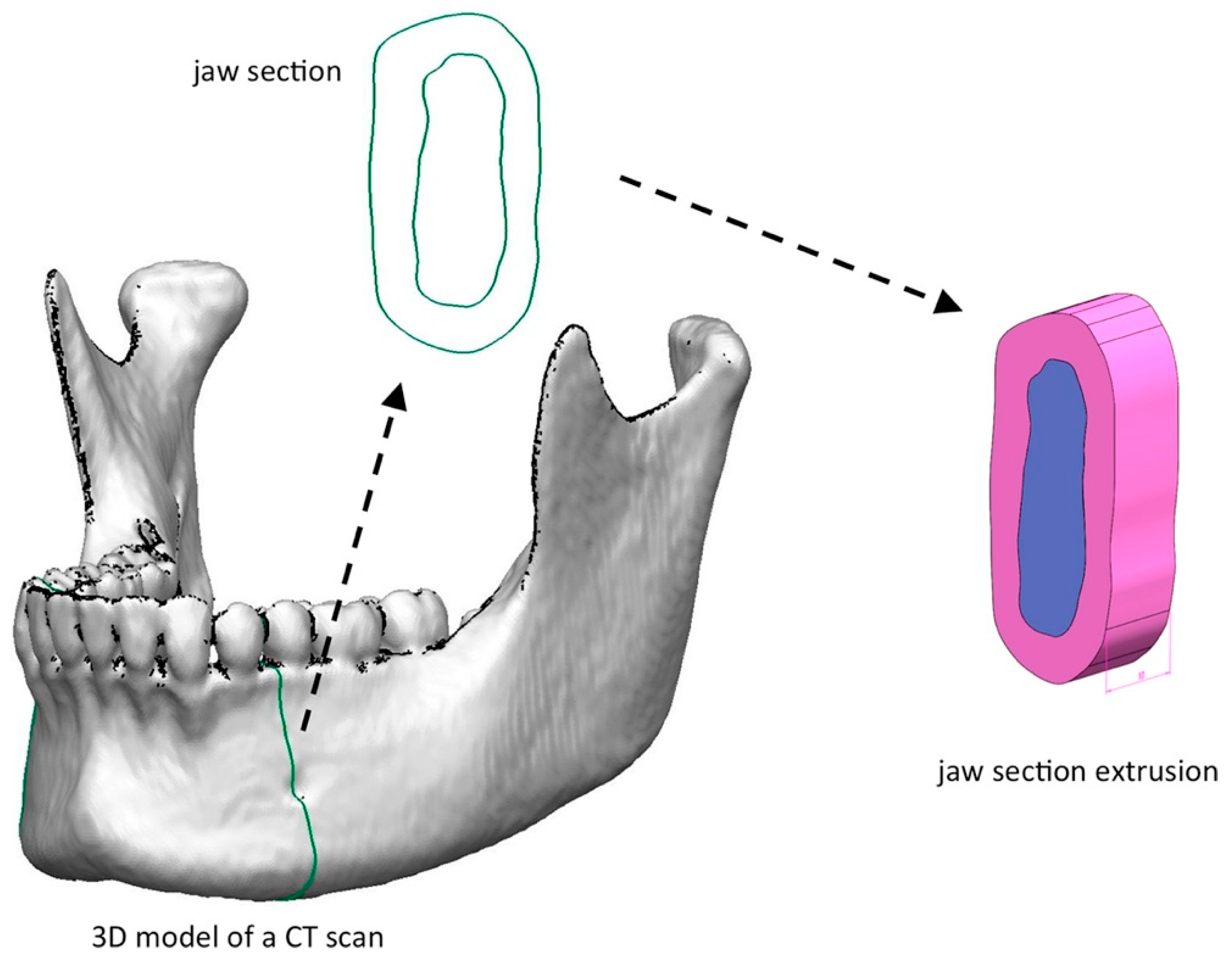
2.5. Finite Element Analysis

The use of finite element analysis (FEA) in oral implantology helps understand the characteristics of the individual implant-prosthetic components, their physical and chemical properties, and the optimal environmental conditions, because it offers the best performance. The FEA is a numerical technique designed to seek approximate solutions to problems described by partial differential equations by reducing the latter to a system of algebraic equations. Although it competes in some limited areas with other numerical strategies (e.g., finite difference method, finite volume method, boundary element method, cell method, spectral method, etc.), FEA maintains a dominant position in the panorama of numerical techniques. In general, finite element analysis lends itself very well to solving partial differential equations when the domain has a complex shape (such as the chassis of a car or the engine of an aeroplane), when the domain is variable (for example, a reaction solid state with variable boundary conditions), when the required accuracy of the solution is not homogeneous on the domain (e.g., in a crash test on a car the required accuracy is greater near the impact zone), and when the sought solution is lacking in regularity [10].
FEA has its origins in the need to solve complex elastic and structural analysis problems in the field of civil and aeronautical engineering. The origins of the method can be traced back to the years 1930–1935 with the works of A. R. Collar and W. J. Duncan, who introduced a primitive form of the structural element in the resolution of an aeroelasticity problem, and to the years 1940–1941 with works by Alexander Hrennikoff and Richard Courant, where both, although in different approaches, shared the idea of dividing the domain of the problem into subdomains of a simple form (the finite elements). However, the actual birth and development of finite element analysis took place in the second half of the 1950s with the fundamental contribution of M. J. Turner of Boeing, who formulated and perfected the Direct Stiffness Method, the first approach to elements Turner’s work found diffusion outside the narrow fields of aerospace engineering, and in particular in civil engineering, through the work of John Argyris at the University of Stuttgart (who in the same years had proposed a formal unification of the method of forces and the displacement method by systematizing the concept of assembling the relations of a structural system starting from the relations of the component elements), and by Clough at the University of Berkeley (who first spoke of FEA and whose collaboration with Turner had given birth to the famous work considered as the beginning of the modern FEA). Other fundamental contributors to the history of FEA include: B. M. Irons, who is responsible for isoparametric elements, the concept of shape function, the patch test, and the frontal solver (an algorithm for solving the linear algebraic system); R. J. Melosh, who framed FEA in the class of Rayleigh-Ritz methods and systematized its variational formulation (a rigorous and famous exposition of the mathematical basis of the method was also provided in 1973 by Strang and Fix); and E. L.Wilson, who developed the first (and largely imitated) open source FEA software, which gave birth to SAP. In 1967 Zienkiewicz published the first book on finite elements. Since the 1970s, FEA has found widespread use as a numerical modelling strategy for physical systems in a wide variety of engineering disciplines, for example, electromagnetism, fluid dynamics, structural calculus, and geotechnics. Over the years, most of the commercial FEA analysis codes were born (NASTRAN®, ADINA®, ANSYS®, ABAQUS®, SAMCEF®, MESHPARTS®, etc.) and are still available today [22].
FEA is applied to physical bodies which can be subdivided into a certain number, sometimes very large, of elements of defined shape and small size. In the continuum, every single finite element is considered a numerical integration field of homogeneous characteristics. The main feature of finite element analysis is discretization through the creation of a grid (mesh) composed of primitives (finite elements) of the coded form (triangles and quadrilaterals for 2D domains, tetrahedra and hexahedrons for 3D domains). On each element characterized by this elementary form, the solution of the problem is assumed to be expressed by the linear combination of functions called basic functions or shape functions. It should be noted that sometimes the function is approximated, and the exact values of the function will not necessarily be those calculated in the points, but the values that will provide the least error over the whole solution. The typical example is that of polynomial functions, so that the overall solution of the problem is approximated with a polynomial function in pieces. The number of coefficients that identify the solution on each element is therefore linked to the degree of the chosen polynomial. This, in turn, governs the accuracy of the numerical solution found. In its original form, and still more widespread, finite element analysis is used to solve problems based on linear constitutive laws. Stress problems are typical, and include deformations in the elastic range and the diffusion of heat inside a material body. Some more refined solutions allow us to explore the behaviour of materials even in a highly non-linear field, hypothesizing plastic or visco-plastic behaviours. In addition, coupled problems are sometimes considered, within which various complementary aspects can be solved simultaneously, each attributable on its own to a FEA separate. Typical in this sense is the geotechnical problem of the behaviour of a given soil (geomechanical field) in the presence of groundwater filtration motions (hydrogeological field). To arrive at the model of the final elements, we follow the fundamental steps, each of which involves the insertion of errors in the final solution:
  • Modelling: this phase is present in all engineering-type studies: we move from the physical system to a mathematical model, which abstracts some aspects of interest from the physical system, focusing attention on a few aggregate variables of interest and “filtering” the remaining ones. For example, when calculating the bending moment of a beam, interactions at the molecular level are not taken into account. The physical system of the complex is divided into subsystems. In the case in question, it is not necessary, or it can be assumed that it is a part belonging to a more complex system, for example, a ship or an aeroplane. The subsystem will then be divided into finite elements to which a mathematical model will be applied. Unlike the analytical treatments, it is sufficient that the chosen mathematical model is suitable for the simple geometries of finite elements. The choice of an element type in a software program is equivalent to an implicit choice of the mathematical model underlying it. The error that can lead to the use of a model must be evaluated with experimental tests, an operation that is generally expensive in terms of time and resources.
  • Discretization: in a numerical simulation it is necessary to pass from an infinite number of degrees of freedom (condition proper to the “continuum”) to a finite number (situation proper to the grid). The discretization, in space or time, aims to obtain a discrete model characterized by a finite number of degrees of freedom. An error is inserted given by the discrepancy with the exact solution of the mathematical model. This error can be appropriately evaluated if there is a mathematical model suitable for the entire structure (and therefore preferable to use concerning FEA analysis), and in the absence of numerical calculation errors, this can be considered true using electronic calculators [23,24].

2.6. Finite Element Analysis and Dental Implants

In the physiology of the stomatognathic apparatus, there are maximum occlusal forces ranging on average from 155 N for the incisors to 208 N for the canines, up to 288 N for the premolars and 565 N for the molars. In particular, under conditions of occlusal stress, the molars can exert maximum occlusal forces of up to 800 N. Otherwise, the maximum masticatory forces vary between 70 N and 150 N. On the other hand, the forces acting on the dental restorations in a patient with a fixed bridge and a replaced molar in one hemi-arch, with the other hemi-arch intact, are on average around 240 N in the hemi-arch where the bridge is present and about 300 N in the intact hemiarch.
These considerations on the maximum occlusal forces and the masticatory forces must be taken into great consideration when evaluating the possible load stress of a prosthetic structure subjected to biomechanical stress in its occlusal physiological function [23,25,26].
The total implant-supported prosthesis today represents the first-choice option, especially in cases of the elderly in which there is a need to anchor the lower classic denture in patients, which is always more difficult to stabilize than the upper prosthesis. It is important to remember that an osseointegrated implant, although it gives good retention and support to the prosthetic, differs significantly from the natural tooth. The most important difference from the biomechanical point of view is the absence of the periodontal ligament (PDL), which in the natural tooth performs the amortization functions of occlusal loads, is involved in proprioceptive sensitivity, and promotes bone regeneration activities. Under a load, the complex movements of a natural tooth first involve the PDL and subsequently the alveolar bone. In an osseointegrated dental implant, in the absence of the cushioning action of the PDL, there is a linear model of the deflection force that depends exclusively on the elastic deformation of the alveolar bone [27].
For these reasons, excessive masticatory loads, which are often not perceived as such by the patient because of the lack of PDL, may lead to implant loss. Among the different types of forces that make the occlusal load the most dangerous are those that are discharged in the transverse direction, that is, those forces which act in the transverse direction or in which the point of application is away from the axis of the implant, since this will tend to rotate or flex. These forces are less favourable and more harmful than axial compression [27].
The main difficulty in simulating the biomechanical behaviour of compensatory bone implant prosthesis, other than the tensile forces, lies in the modelling of the maxilla and mandible and their reaction to the load. To perform this analysis, these parameters are usually used: Young’s modulus (Exx, Eyy, Ezz), Poisson’s ratio (νxx, νyy, νzz), tangential modulus (Gxx, Gyy, Gzz), and density (ρ) [28,29,30,31]. The bone tissues (cortical and cancellous), arere considered orthotropic (Table 1).

2.7. Von Mises

The criterion of maximum distortion (commonly known in the technical field as the von Mises criterion, even if the origin is uncertain) is a resistance criterion relative to ductile materials (it is therefore a yield criterion) which are isotropic and have equal tensile and compressive strength. In the three-dimensional space of the principal stresses, this domain corresponds to a cylinder with a circular section with an axis placed in the tri-sector of the positive octant. This cylinder circumscribes the straight prism with a hexagonal base associated with the criterion of maximum tangential stress. The von Mises criterion assumes that the yield strength of the material is reached when the distortion energy reaches a limit value, where the distortion is the component of the deformation that causes a change in the shape, but not in the volume, of a volume element. The criterion can originally be attributed to Maxwell (1856), who proposed it based on purely mathematical–formal considerations. In a more strictly mechanical context, the criterion was subsequently proposed by Richard von Mises (1913) and, almost independently and based on different considerations, by Huber (1904) and Hencky (1924) [32].

2.8. Fracture Mechanics Analysis

Bone has a hierarchical structure consisting of collagen, water, and minerals. The arrangement of these components in different functional units creates a light and resistant structure, which is multifunctional and able to adapt to different mechanical environments. To understand the influence of bone quality, characterized by the bone material composition and structural design, on its mechanical properties, it is necessary to study how bone resists fracture at different length scales. As a living tissue, bone has a unique ability to repair itself through growth and remodelling processes, which give it a dynamic structure. The remodelling process allows the bone structure to adapt to external changes. This continuous process also removes damaged bone tissue and replaces it with new bone material. However, excessive remodelling of microdamage induced by ageing and bone disease degrades bone quality and increases the possibility of fracture. Therefore, to better understand fracture phenomena in bone, it is necessary to improve our understanding of changes in structure and composition related to ageing, which, in turn, affect the mechanical properties of bone. At the microstructural level, the main structural features that control cortical bone fracture toughness include osteons, cement lines, and extended discontinuities such as Haversian canals. Such discontinuities could turn out to be sites of stress concentration for the initiation of cracks. Finally, at the microscale and beyond, bone microstructures and material properties vary with age, which significantly affects bone toughness at the macroscale [33].
Most FEA analyses of bone deformation and nanoscale failure used a two-dimensional representation of the staggered arrangement of mineral platelets in a collagen matrix. For example, Raeisi Najafi et al. [34] investigated the growth trajectory of cracks in cortical bone using a FEA model. Their results show that a trajectory of microcracks deviates from the osteon [33].
Some studies have used a cohesive FEA technique to model bone fracture at the microscale. Ural and collaborators used this modelling technique [35] in an idealized two-dimensional model of a single osteon, surrounded by a cement line and an interstitial bone, and investigated the mechanisms influencing possible crack deflection and penetration near the concrete lines. Subsequently, they expanded their study to a multi-osteogenic model based on microscopic images of cross-sections of human cortical bone 2 [33,36].
The extended finite element analysis (XFEA) has also been used to study the growth path of the fissure in a Haversian cortical bone. In this way, it is possible to model the growth of multiple cracks in the human cortical bone under tension to create a constitutive law at the macroscopic level and to study the influence of microstructure morphology on bone failure. A two-dimensional fracture model was developed for osteonal bovine cortical bone taking into account its microstructure. The topology of the bone microstructure was obtained using an optical microscope and the mechanical properties of the microstructural features were measured by a nanoindentation method. It confirmed a significant role for the bone microstructure in the crack propagation path [33].

2.9. Oral Surgery, Guided Surgery and Dental Implant Surgery

The positioning of an implant fixture within the bone structure must be considered as damage to the integrity of the organism. Around an implant, there is always an empty micrometric space in which complex biological phenomena occur. Ischemia of the tissues with necrobiosis occurs immediately on the bone side. The increase in vascular permeability in the surgery area determines the pouring of undifferentiated mesenchymal cells to fill the gap between the bone surface and the implant (cell and vascular migration and colonization). After the first four days, cell differentiation and the organization of the peri-prosthetic tissue occur. This allows the removal of cellular and bone debris in necrosis operated by macrophages to begin the reparative phase.
New bone formation follows all the stages that characterize direct ossification: the arrival of osteoblasts, deposition of osteoid tissue, and formation of immature bone with intertwined fibres.
Around the sixth week, the primitive bone is progressively reabsorbed and replaced by mature lamellar bone; this process then leads to the formation of bone around the inserted implant.
Implant surgery is a branch of oral surgery, entrusted to a professional surgeon who aims at the positioning of one or more implant fixtures for prosthetic, rehabilitative, or orthodontic purposes.
The insertion of the fixture can take place at different times:
(1)
A surgical period where, after osseointegration, the gum will not have to be re-incised to see the position of the implant, as is the case for transmucosal implants;
(2)
Two surgical stages, as is the case for fully submerged implants, in which the gum will have to be re-incised after osseointegration to see where the implant is and allow it to be connected to the supra-body prosthetic devices.
Alongside these two canonical methods, there are others linked above all to the timing of implant insertion concerning the extraction of the dental element that will be replaced:
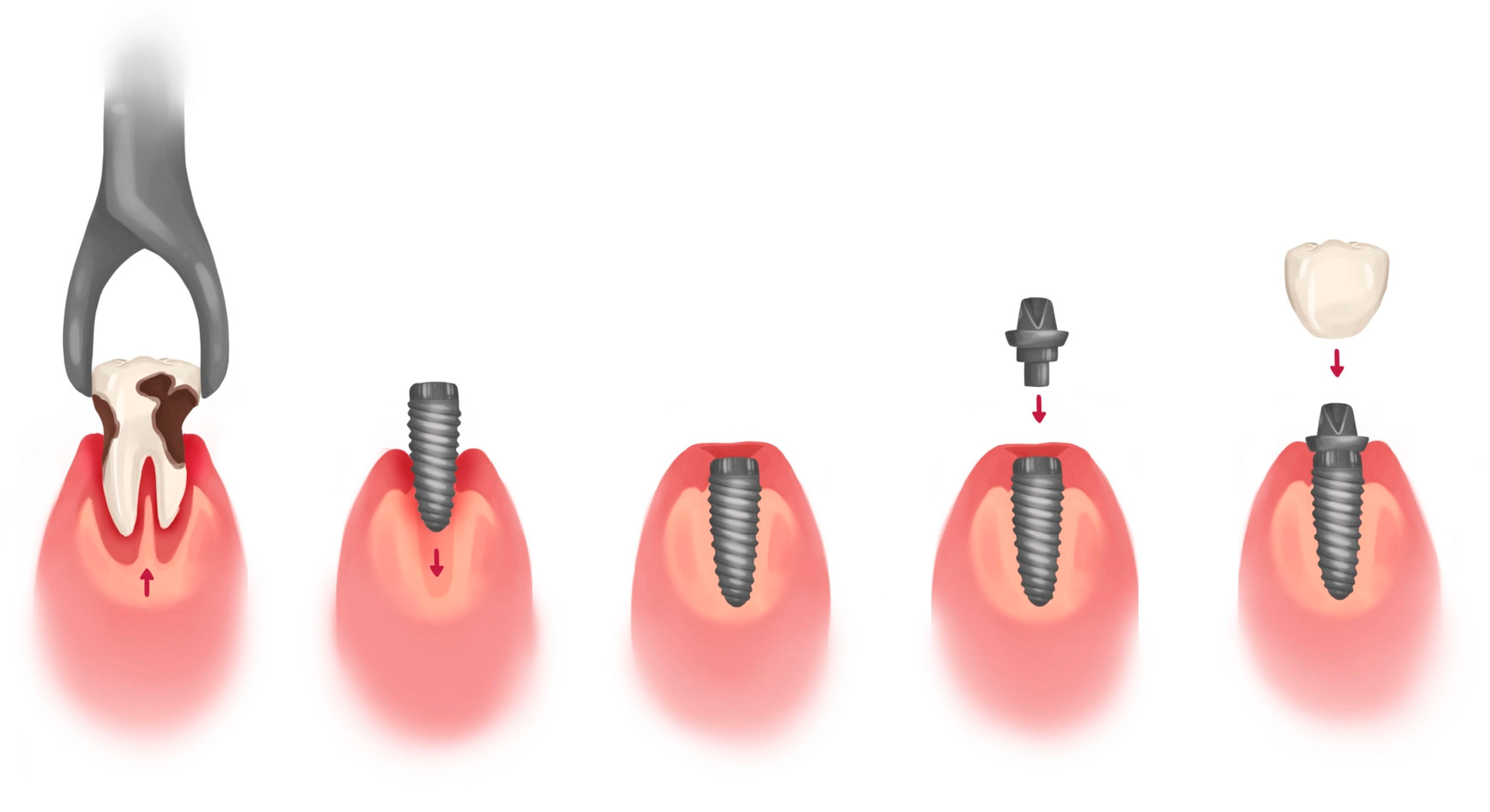
  • Immediate post-extraction implants, in which the implant is inserted immediately after the extraction;
  • Deferred post-extraction implants, in which the insertion of the implant takes place a few weeks after dental extraction when healing of the molal tissues has occurred;
  • Delayed post-extraction implants, in which the insertion of the implant takes place 12–16 after weeks of dental extraction;
  • Late post-extraction implants, in which the implant is inserted 3–4 months after extraction.
The positioning of the implant fixture is a surgical intervention that should take place in sterile conditions. After having carried out an antiseptic wash to the area affected by surgery and the peri-oral area, we proceed to the loco-regional anaesthesia phase of the affected area. Manual implant surgery subsequently provides for the surgical incision and the preparation of a full-thickness mucoperiosteal flap with an incision that varies according to the district and the number of implants to be placed. After the exposure of the cortical bone, drilling with a pilot drill is carried out if the bone surface is regular, using a previously planned inclination and depth. Subsequently, the calibre of implant preparation is increased by using drills with a gradually larger diameter until the one corresponding to the implant is reached, depending on the surgical kit of drills used. At this point, it will be possible to proceed with the positioning of the implant fixture, which only now must be removed from its sterile packaging, and must be positioned on the site of the implant preparation in the shortest possible time to limit the risk of contamination. At this point, the screwing of the latter proceeds until the desired position is reached according to the maximum torque recommended by the implant manufacturer. Once the mounting device has been removed, where present, the cap screw will be positioned, and then the surgical flap will be repositioned. After osseointegration, it will be possible to proceed to a new, possibly reduced, surgical flap, and to the positioning of the healing abutment. Once the soft tissues have matured, the impression can then be taken via analogue transfer, or body scan for a digital impression, and then the prosthetic phase begins (Figure 2).
This describes just one of the surgical procedures for inserting dental implants. For clarity and brevity of speech other techniques, such as those using osteotomes or ultrasonic instruments, are not described [37].

3. Results

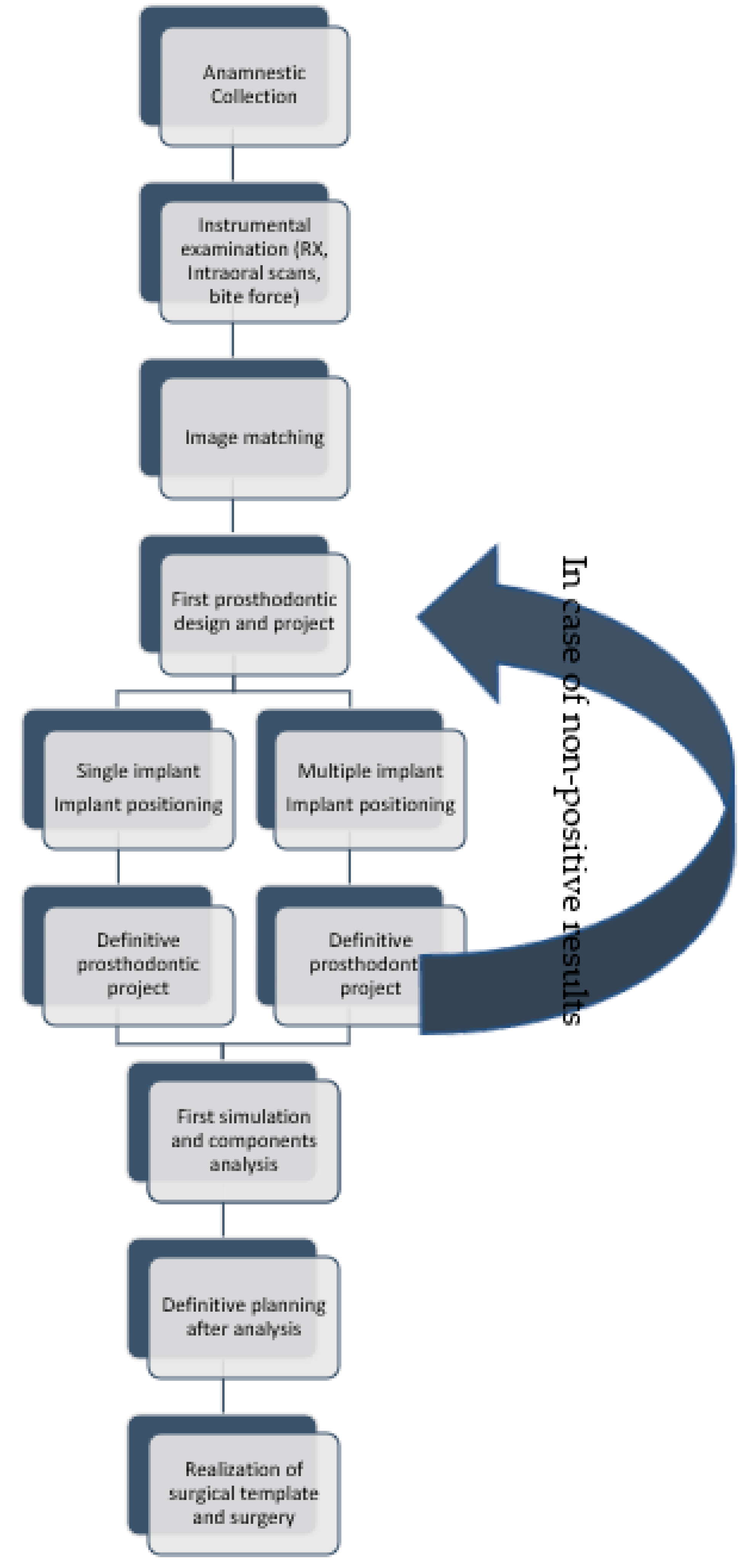
3.1. Digital-Assisted Pre-Guided Implant Surgery

Through the interpretation of the materials and methods, it is possible to devise the following protocol. To summarize the protocol, there are seven important phases. The first phase involves the screening of all patients with contraindications to implant therapy and the anamnestic collection, to be carried out in each case. Subsequently, we proceed with the radiographic instrumental evaluation (possibly with intraoral scanners and masticatory force meters). We then proceed with the matching of these files and with the transformation of the X-ray files (.dicom) into 3D design files (.stl), and the first rehabilitation design is carried out. Once the project is completed, we proceed to the simulation using the finite element analysis, and subsequently with tools such as FEA and von Mises analysis. If the results are optimal, only then can it be possible to proceed with the creation of the surgical guide, and therefore with the surgery. If the simulation does not give the expected results then, we will start again from point 4, with a new and modified simulation (Figure 3).
Assuming the case is the same for different implants, it is possible to draw as a conclusion a new method useful for implant-prosthetic planning, which aims to improve the short–long term predictability of oral rehabilitations. This method can be applied to simple or complex type rehabilitations and can be made more precise by improving the resolution of the FEA simulations. Furthermore, it is possible to calculate not only the main components of the restorations, such as prostheses, implants, and bone, but also all the smaller components, such as abutments, passing screws, or other structures present.
The FEA analysis allows us to carry out a biomechanical simulation of the simulated masticatory forces on a specific component of the implant-prosthetic. It begins with an intraoral scan and a three-dimensional radiographic examination of our patient. Once these images have been matched, it is possible to proceed with the realization of the .stl model. Theoretically, a determined value of bone density can be assigned according to the identified Hounsfield scale of the radiographic .dicom images (Figure 3 and Figure 4).
The masticatory forces can also be measured in vivo on the patient with the use of precision electromyographs, with customized forks that measure the masticatory force, currently already on the market.
Once these values have been obtained along with the .stl model of our patient, we can proceed with the realization of the prosthesis and the surgical planning.
Having roughly identified, in the first instance, the ideal position of the dental elements to be rehabilitated, it is therefore possible to proceed with the digital positioning of the implant fixtures, respecting where possible the patient’s bone anatomy, or evaluating any contextual regenerative manoeuvres. Only at this point will it be possible to proceed with the positioning of the abutment and therefore with the design of the definitive prosthesis.
Having obtained this structure, it will be possible to proceed with the simulation by applying the FEA analysis with cycles as described above and with the forces previously measured. If the analysis shows stress peaks on the cortical or bone marrow, at this point it will be possible to proceed with the rescheduling of the implant placement, to reduce the stress on the hard tissues. This is obviously done to obtain an image in which the distribution of the loads is uniform and allows the correct biomechanical function. It is known how bone is not a static structure, but is in fact highly dynamic, and can respond to certain mechanical stimuli, as is mentioned by Wolff’s law [40].
However, if the stimulus is excessive, this can induce bone damage or resorption, which can indeed trigger peri-implant disease or the loss of the fixture itself. Usually, in the biomechanical field, the tension distribution is analysed with particular attention, both in biological structures, to see how much the coupling with an artificial structure (e.g., prosthesis, implant) modifies their structural response to external stresses, and in artificial structures to check their resistance capacity. The identification of the distribution and extent of tensions in a structure is important as it highlights which areas are the most stressed and at risk of rupture. Furthermore, in the case of biological tissues, it can identify necrosis or hypertrophy, as well as areas which are less stressed and could induce atrophy. In an analysis of the stress state of biomechanical systems in which the tension values in areas of interface with the implant were compared, particular attention was paid to the mandibular cortical bone, as it was one of the most stressed areas. Experience indicates these as being the areas most affected by bone resorption. According to other studies [32], the forces transferred by dental implants on cancellous bone and cortical bone vary between 4–13 MPa and 12–29 Mpa, respectively, according to the implant geometry. Once an optimal analysis has been obtained from the point of view of the distribution of forces on the cortical and medullary bone, we can then move on to the evaluation of the implant-prosthetic components, to correctly distribute the forces on these as well. This phase can be much more difficult if involving prostheses screwed on four, five, or six dental implants.
Only after the last simulation and the single analysis of all components will it be possible to consider the planning complete and move on to the next phase: Making a surgical guide (template) that the surgeon will use to place the implants as planned. For this reason, the manufacturers of dental implants are also often involved, and in recent years they have created surgical kits for the positioning of implants with a template. Surgery thus becomes one of the simplest phases. Once the template has been positioned, the protocol and planning are followed.
The following phases can therefore be summarized:
  • Anamnestic collection;
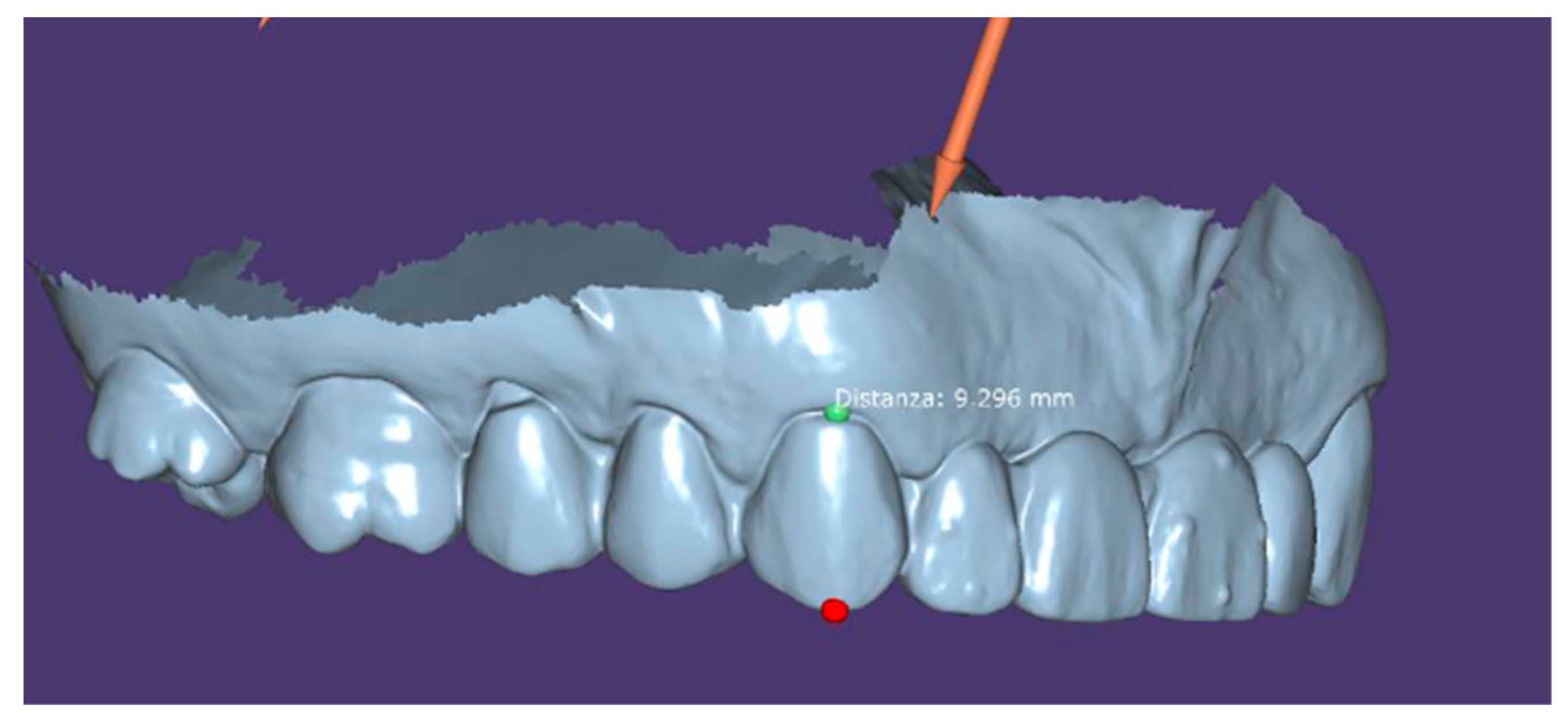
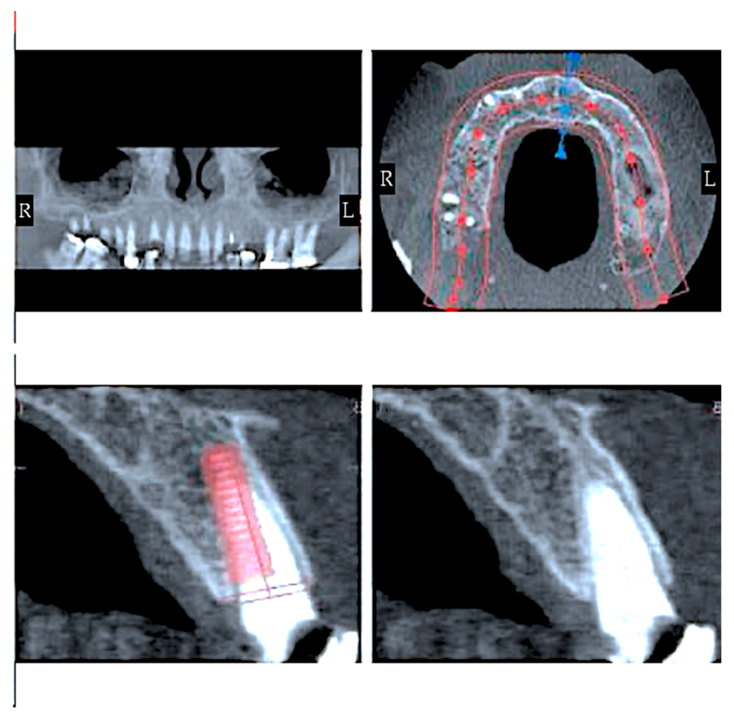
  • Instrumental examinations (three-dimensional radiography, intraoral optical impression);
  • Image matching and transformation from .dicom to .stl;
  • The first design of a prosthodontic with an advantageous position from a biomechanical point of view:
    Implant positioning respecting anatomy as much as possible;
    Realization of definitive prosthetic design;
  • First simulation:
    Analysis of force peaks and attenuation by moving dental implant;
    Definitive implant planning;
  • Realization of the surgical guide;
  • Surgical intervention (Figure 5).

3.2. Fi-Index Tool

This manuscript has been checked with the Fi-index tool and obtained a score of 0.88 for the first author only on the date 10 January 2023 according to SCOPUS® for all Authors [41,42]. The fi-index tool aims to ensure the quality of the reference list and limit any auto-citations.

4. Discussion

From what has been said above, it is clear how important it is to be able to have electronic and computer equipment performing to such an extent as to allow the creation of an ad hoc simulation of this kind for each patient during the planning of implant insertion. As already discussed in different studies, the time to perform a single simulation of this kind can be more than 30 min. The difficulties still lie in being able to “discretize” the patient’s bone components with the lowest possible error rate, starting with the three-dimensional radiographic images contained in the .dicom files. The transformation of .dicom into .stl is currently possible. The quality of the radiographic images is essential, and a bone density value should be applied, therefore biomechanical values must be measured, depending on the radiographic value identified in the grayscale (Hounsfield scale). The finite element analysis is a useful aid for the assessment of stress rising in the bone due to the presence of prosthetic devices. It represents an easy way to investigate complex biomechanical systems instead of experimental techniques that are difficult to apply. To perform a reliable simulation, several fundamental parameters have to be taken into account, such as the bone tissue material model, the state of osseointegration of the implant, and the preload of the internal screw [43]. A study by the research group of the University of Messina [32] highlighted how evident the difference in the distribution of forces on the bone tissue and any case of all peri-implant tissues when the direction of the load changes. Considering that it is impossible to obtain a “pure” axial load during chewing, it would therefore be advisable to be able to plan the implant insertion after a simulation of this type. According to Michailidis et al. [44], the increased rigidity of the implant material develops high stresses, while the adjacent cancellous bone is deformed, partially absorbing the induced load, thus determining a lower distribution of stresses. This is evident along the entire length of implant fixation and in all loading scenarios, which has been associated with the geometry of the cylindrical implant screw.
The simulations revealed that the length of implant fixation (length of the embedded screw) is of paramount importance for long-term stability. Poorly osseointegrated implants are insufficiently supported and could lead to fractures even under low forces. Bone resorption, which alters the initial implant/crown ratio, has a significant effect on the biomechanical behaviour of the prosthesis. Detection of the implant in the order of 15% of the total embedded length will lead to increased implant fatigue and possible fracture, even in mild load scenarios. The results of our study were verified by comparing simulated stress fields with fractured (clinically recovered) implants. The correlation confirmed the realistic development of stress, as the predicted critical regions calculated by the model are consistent with the fracture site of the prosthesis [44].
The possibility of creating a virtual articulator, measuring the patient’s masticatory force, and creating a simulation that is as close to reality as possible would certainly allow safe and predictable rehabilitation over time, identifying the best position for implant insertion and for prosthetic design, allowing to limit the number of medium–long term implant failures linked to peri-implant processes induced by biomechanical parameters. If the loss of an implant occurs shortly after having performed a dental implant surgery, before osseointegration has taken place, then the probable cause is not attributable to peri-implantitis and can be:
  • Insufficient sterilization of the operating field;
  • Overheating of the bone;
  • The lack of primary stability at the time of its insertion;
  • The occlusal overload of the implant screw.
Peri-implantitis is a bacterial infection that affects dental implants. This is determined by the accumulation of plaque and tartar and therefore poor or incorrect home oral hygiene associated with the lack of professional oral hygiene sessions, which in subjects predisposed to periodontitis and therefore to peri-implantitis should have a quarterly frequency. The main causes of peri-implantitis are:
  • genetic predisposition for periodontitis
  • the inaccurate crown which causes greater plaque accumulation around the implant
  • lack of the contact point that determines food impaction, i.e., accumulation of food and plaque between the teeth
  • presence of cement under the gum which is colonized by bacteria
The latter is probably the main cause of peri-implantitis. For this reason, screw-retained prostheses on implants are now preferred. The onset of peri-implantitis is linked to the conditions that cause greater accumulation of plaque and tartar under the gingiva. Generally, the infection manifests itself with spontaneous bleeding and swelling of the affected area, the presence of a metallic taste on salivation, and ultimately the mobility of the dental implant. Peri-implantitis acts similarly to periodontitis, causing bone resorption around the implants and causing the inevitable loss of the prosthesis. In any case, infection involving dental implants is a slow process, the more serious consequences of which, such as the loss of the dental implant, can be avoided through bone regeneration surgery. When the implant is mobile, unlike the dental elements, it is always lost. In any case, if the symptoms of peri-implantitis are present, it is necessary to immediately contact an expert implantologist and periodontist for a thorough examination and radiographic examination. An intraoral radiograph, a periodontal probe and a clinical examination will be sufficient to make a diagnosis of peri-implantitis. The peri-implant area could be affected by non-axial loading, cantilever prosthetic elements, crown/implant ratio, type of implant–abutment connection, misfits, properties of restoration materials and antagonistic tooth. However, the macro-architectural design of the implant establishes initial mechanical fixation, which is crucial in minimizing implant mobility in the first 3–4 weeks of function. In the search for a new macro-architectural design, the idea of adding a wing to the implant for extra primary stability was raised. Finite element analysis of the ‘winged’ implant, in comparison to a regular implant, revealed that when a 20 kg force is applied at an off-axis angle of 20°, the amount of maximal displacement at the neck of a regular implant is 60% higher than observed with the ‘winged’ implant. To determine the clinical efficacy of this new implant, a study was undertaken to evaluate the implant in both jaws under conditions of immediate function. This implant will be presented with finite element analysis and animal experiments with an explanation of the biomechanics of peri-implantitis. Another study by Macedo et al. [39], shows how the stresses analysed with the von Mises method on the cortical bone were higher than those recorded on the trabecular bone, by the axial or oblique load. In addition, Morse taper implants showed a higher volume of peri-implant bone at low stress and a lower volume of peri-implant bone at high stress. Therefore, Morse taper implant systems revealed better biomechanical behaviour than external hex implants, concerning significant bone volume subjected to low stress intensity. This also provides important information regarding the influence of an internal component of the dental implant on the bone. Artificial intelligence (AI) can assist in dental implant positioning by analysing patient-specific data, such as CT scans, to determine the optimal location for implant placement [45]. AI algorithms can use image recognition and deep learning techniques to identify and analyse the bone structure, tooth alignment, and soft tissue characteristics to create a 3D model of the patient’s mouth. This model can then be used to simulate different implant placement scenarios and predict the most suitable position for the implant. AI can also be used during the surgery to provide real-time guidance to the dentist, improving accuracy and reducing the risk of complications. Overall, AI has the potential to enhance the precision and efficiency of dental implant procedures, resulting in better outcomes for patients [46,47,48,49]. At this point, it is natural to add that the application of artificial intelligence could further screen all these phases which are currently entrusted to the clinician and to an expert in simulations by directly proposing a series of projects compatible with oral biomechanics and entrusting the clinician only with the choice last of the best solution.

Limitations

The main limitation of this study lies purely in the fact that it is currently not possible to carry out such a simulation, which would require not only a positive opinion from an ethics committee, but also resources to collect the sample of patients along with a control group, and to perform both simulations and surgical interventions with all surgical material and prosthetic implants.

5. Conclusions

The analyses derived from bioengineering would certainly allow much safer and more predictable rehabilitation. Nowadays, FEA analyses allow us to improve implant fixtures, connections, and individual components. This is thanks to cyclical simulations and continuous scientific research in this area. Having such an instrument chair-side and available to the dentist is a very important goal. Unfortunately, these simulations still require very high performance and expensive hardware, and the simulation times are very long. Among other things, the software is not easy to use, and a dentist, albeit one helped by a dental technician (who by now has necessarily had to apply himself to the digital world), does not have the skills or tools necessary to carry out this type of work.
The possibility of carrying out simulations of this type, after having performed simple instrumental examinations which are now part of clinical practice, would allow simple and complex safe rehabilitations not only in the short but also in the long term.

Author Contributions

Conceptualization, methodology, investigation, data curation, writing—original draft preparation, writing—review and editing, L.F.; supervision, A.M.; project administration, M.C. All authors have read and agreed to the published version of the manuscript.

Funding

This research received no external funding.

Institutional Review Board Statement

Not applicable.

Informed Consent Statement

Not applicable.

Data Availability Statement

Data is available on request to the corresponding author.

Conflicts of Interest

The authors declare no conflict of interest.

References

  1. Urist, M.R. Bone: Formation by autoinduction. Science 1965, 150, 893–899. [Google Scholar] [CrossRef] [PubMed]
  2. Pihlstrom, B.L.; Michalowicz, B.S.; Johnson, N.W. Periodontal diseases. Lancet 2005, 366, 1809–1820. [Google Scholar] [CrossRef] [Green Version]
  3. Diesendorf, M. The mystery of declining tooth decay. Nature 1986, 322, 125–129. [Google Scholar] [CrossRef]
  4. Fiorillo, L. Oral Health: The First Step to Well-Being. Medicina 2019, 55, 676. [Google Scholar] [CrossRef] [PubMed] [Green Version]
  5. Schmidt, A.; Klussmann, L.; Wöstmann, B.; Schlenz, M.A. Accuracy of Digital and Conventional Full-Arch Impressions in Patients: An Update. J. Clin. Med. 2020, 9, 688. [Google Scholar] [CrossRef] [PubMed] [Green Version]
  6. Tomita, Y.; Uechi, J.; Konno, M.; Sasamoto, S.; Iijima, M.; Mizoguchi, I. Accuracy of digital models generated by conventional impression/plaster-model methods and intraoral scanning. Dent. Mater. J. 2018, 37, 628–633. [Google Scholar] [CrossRef] [PubMed] [Green Version]
  7. Tallarico, M.; Ceruso, F.M.; Muzzi, L.; Meloni, S.M.; Kim, Y.-J.; Gargari, M.; Martinolli, M. Effect of Simultaneous Immediate Implant Placement and Guided Bone Reconstruction with Ultra-Fine Titanium Mesh Membranes on Radiographic and Clinical Parameters after 18 Months of Loading. Materials 2019, 12, 1710. [Google Scholar] [CrossRef] [Green Version]
  8. Zhang, C.; Li, Z.; Yang, R. Digital Design and Application of 3D Printed Surgical Guide for Long Screw Fixation of Condylar Sagittal Fracture. J. Craniofac. Surg. 2021, 32, e632–e634. [Google Scholar] [CrossRef]
  9. Gherlone, E.F.; Ferrini, F.; Crespi, R.; Gastaldi, G.; Cappare, P. Digital impressions for fabrication of definitive "all-on-four" restorations. Implant Dent. 2015, 24, 125–129. [Google Scholar] [CrossRef]
  10. Kolata, G.B. The finite element method: A mathematical revival. Science 1974, 184, 887–889. [Google Scholar] [CrossRef]
  11. Makin, S. Searching for digital technology's effects on well-being. Nature 2018, 563, S138–S140. [Google Scholar] [CrossRef] [PubMed] [Green Version]
  12. Kim, S.K.; Heo, S.J.; Koak, J.Y.; Lee, J.H.; Lee, Y.M.; Chung, D.J.; Lee, J.I.; Hong, S.D. A biocompatibility study of a reinforced acrylic-based hybrid denture composite resin with polyhedraloligosilsesquioxane. J. Oral Rehabil. 2007, 34, 389–395. [Google Scholar] [CrossRef] [PubMed]
  13. John, J.; Gangadhar, S.A.; Shah, I. Flexural strength of heat-polymerized polymethyl methacrylate denture resin reinforced with glass, aramid, or nylon fibers. J. Prosthet. Dent. 2001, 86, 424–427. [Google Scholar] [CrossRef] [PubMed]
  14. Lee, J.H.; Jun, S.K.; Kim, S.C.; Okubo, C.; Lee, H.H. Investigation of the cytotoxicity of thermoplastic denture base resins. J. Adv. Prosthodont. 2017, 9, 453–462. [Google Scholar] [CrossRef] [PubMed] [Green Version]
  15. Sher, J.; Kirkham-Ali, K.; Luo, J.D.; Miller, C.; Sharma, D. Dental Implant Placement in Patients With a History of Medications Related to Osteonecrosis of the Jaws: A Systematic Review. J. Oral Implantol. 2021, 47, 249–268. [Google Scholar] [CrossRef]
  16. Norcia, A.; Cicciù, M.; Matacena, G.; Bramanti, E. Dental implant positioning by using the root way. A predictable technique for postextractive surgery. Minerva. Stomatol. 2016, 65, 393–402. [Google Scholar]
  17. Camardella, L.T.; Breuning, H.; de Vasconcellos Vilella, O. Accuracy and reproducibility of measurements on plaster models and digital models created using an intraoral scanner. J. Orofac. Orthop. 2017, 78, 211–220. [Google Scholar] [CrossRef]
  18. Tallarico, M. Computerization and Digital Workflow in Medicine: Focus on Digital Dentistry. Materials 2020, 13, 2172. [Google Scholar] [CrossRef]
  19. Rodrigues, S.B.; Franken, P.; Celeste, R.K.; Leitune, V.C.B.; Collares, F.M. CAD/CAM or conventional ceramic materials restorations longevity: A systematic review and meta-analysis. J. Prosthodont. Res. 2019, 63, 389–395. [Google Scholar] [CrossRef]
  20. Ferrini, F.; Sannino, G.; Chiola, C.; Capparé, P.; Gastaldi, G.; Gherlone, E.F. Influence of Intra-Oral Scanner (I.O.S.) on The Marginal Accuracy of CAD/CAM Single Crowns. Int. J. Environ. Res. Public Health 2019, 16, 544. [Google Scholar] [CrossRef] [Green Version]
  21. Cervino, G.; Fiorillo, L.; Arzukanyan, A.V.; Spagnuolo, G.; Cicciu, M. Dental Restorative Digital Workflow: Digital Smile Design from Aesthetic to Function. Dent. J. 2019, 7, 30. [Google Scholar] [CrossRef] [Green Version]
  22. Clough, R. Thoughts about the origin of the finite element method. Comput. Struct. 2001, 79, 2029–2030. [Google Scholar] [CrossRef]
  23. Cervino, G.; Fiorillo, L.; Arzukanyan, A.; Spagnuolo, G.; Campagna, P.; Cicciù, M. Application Of Bioengineering Devices For The Stress Evaluation In Dentistry: The Last 10 Years Fem Parametric Analysis Of Outcomes And Current Trends. Minerva Stomatol. 2020, 69, 55–62. [Google Scholar] [CrossRef] [PubMed]
  24. Cicciù, M.; Cervino, G.; Milone, D.; Risitano, G. FEM investigation of the stress distribution over mandibular bone due to screwed overdenture positioned on dental implants. Materials 2018, 11, 1512. [Google Scholar] [CrossRef] [PubMed] [Green Version]
  25. Cicciù, M.; Cervino, G.; Milone, D.; Risitano, G. FEM analysis of dental implant-abutment interface overdenture components and parametric evaluation of Equator® and Locator® prosthodontics attachments. Materials 2019, 12, 592. [Google Scholar] [CrossRef] [Green Version]
  26. D’Amico, C.; Bocchieri, S.; Sambataro, S.; Surace, G.; Stumpo, C.; Fiorillo, L. Occlusal Load Considerations in Implant-Supported Fixed Restorations. Prosthesis 2020, 2, 252–265. [Google Scholar] [CrossRef]
  27. Yamanishi, Y.; Yamaguchi, S.; Imazato, S.; Nakano, T.; Yatani, H. Influences of implant neck design and implant–abutment joint type on peri-implant bone stress and abutment micromovement: Three-dimensional finite element analysis. Dent. Mater. 2012, 28, 1126–1133. [Google Scholar] [CrossRef] [Green Version]
  28. Zhang, Y.; Lawn, B.R. Evaluating dental zirconia. Dent. Mater. 2019, 35, 15–23. [Google Scholar] [CrossRef]
  29. Zhang, Y.; Lawn, B.R. Novel Zirconia Materials in Dentistry. J. Dent. Res. 2018, 97, 140–147. [Google Scholar] [CrossRef]
  30. Hanawa, T. Zirconia versus titanium in dentistry: A review. Dent. Mater. J. 2020, 39, 24–36. [Google Scholar] [CrossRef] [Green Version]
  31. Filardi, V. Stress shielding FE analysis on the temporomandibular joint. J. Orthop. 2020, 18, 63–68. [Google Scholar] [CrossRef] [PubMed]
  32. Fiorillo, L.; Cicciù, M.; D'Amico, C.; Mauceri, R.; Oteri, G.; Cervino, G. Finite Element Method and Von Mises Investigation on Bone Response to Dynamic Stress with a Novel Conical Dental Implant Connection. Biomed. Res. Int. 2020, 2020, 2976067. [Google Scholar] [CrossRef] [PubMed]
  33. Sabet, F.A.; Raeisi Najafi, A.; Hamed, E.; Jasiuk, I. Modelling of bone fracture and strength at different length scales: A review. Interface Focus 2016, 6, 20150055. [Google Scholar] [CrossRef] [PubMed] [Green Version]
  34. Najafi, A.R.; Arshi, A.R.; Eslami, M.R.; Fariborz, S.; Moeinzadeh, M.H. Micromechanics fracture in osteonal cortical bone: A study of the interactions between microcrack propagation, microstructure and the material properties. J. Biomech. 2007, 40, 2788–2795. [Google Scholar] [CrossRef] [PubMed]
  35. Mischinski, S.; Ural, A. Finite Element Modeling of Microcrack Growth in Cortical Bone. J. Appl. Mech. 2011, 78, 041016. [Google Scholar] [CrossRef]
  36. Mischinski, S.; Ural, A. Interaction of microstructure and microcrack growth in cortical bone: A finite element study. Comput. Methods Biomech. Biomed. Eng. 2013, 16, 81–94. [Google Scholar] [CrossRef]
  37. Makary, C.; Menhall, A.; Zammarie, C.; Lombardi, T.; Lee, S.Y.; Stacchi, C.; Park, K.B. Primary Stability Optimization by Using Fixtures with Different Thread Depth According To Bone Density: A Clinical Prospective Study on Early Loaded Implants. Materials 2019, 12, 2398. [Google Scholar] [CrossRef] [Green Version]
  38. Gluckman, H.; Salama, M.; Du Toit, J. Partial Extraction Therapies (PET) Part 2: Procedures and Technical Aspects. Int. J. Periodontics Restor. Dent. 2017, 37, 377–385. [Google Scholar] [CrossRef]
  39. Macedo, J.P.; Pereira, J.; Faria, J.; Pereira, C.A.; Alves, J.L.; Henriques, B.; Souza, J.C.M.; López-López, J. Finite element analysis of stress extent at peri-implant bone surrounding external hexagon or Morse taper implants. J. Mech. Behav. Biomed. Mater. 2017, 71, 441–447. [Google Scholar] [CrossRef] [Green Version]
  40. Frost, H.M. Wolff's Law and bone's structural adaptations to mechanical usage: An overview for clinicians. Angle Orthod. 1994, 64, 175–188. [Google Scholar] [CrossRef]
  41. Fiorillo, L. Fi-Index: A New Method to Evaluate Authors Hirsch-Index Reliability. Publ. Res. Q. 2022, 38, 465–474. [Google Scholar] [CrossRef]
  42. Fiorillo, L.; Cicciù, M. The Use of Fi-Index Tool to Assess Per-manuscript Self-citations. Publ. Res. Q. 2022, 38, 684–692. [Google Scholar] [CrossRef]
  43. Cicciù, M.; Cervino, G.; Terranova, A.; Risitano, G.; Raffaele, M.; Cucinotta, F.; Santonocito, D.; Fiorillo, L. Prosthetic and Mechanical Parameters of the Facial Bone under the Load of Different Dental Implant Shapes: A Parametric Study. Prosthesis 2019, 1, 41–53. [Google Scholar] [CrossRef] [Green Version]
  44. Michailidis, N.; Karabinas, G.; Tsouknidas, A.; Maliaris, G.; Tsipas, D.; Koidis, P. A FEM based endosteal implant simulation to determine the effect of peri-implant bone resorption on stress induced implant failure. Biomed. Mater. Eng. 2013, 23, 317–327. [Google Scholar] [CrossRef]
  45. Alqutaibi, A.Y. Artificial intelligence (AI) models show potential in recognizing the dental implant type, predicting implant success, and optimizing implant design. J. Evid. -Based Dent. Pract. 2023, 101836. [Google Scholar] [CrossRef]
  46. Revilla-León, M.; Gómez-Polo, M.; Vyas, S.; Barmak, B.A.; Galluci, G.O.; Att, W.; Krishnamurthy, V.R. Artificial intelligence applications in implant dentistry: A systematic review. J. Prosthet. Dent. 2021. [Google Scholar] [CrossRef]
  47. Roy, S.; Dey, S.; Khutia, N.; Roy Chowdhury, A.; Datta, S. Design of patient specific dental implant using FE analysis and computational intelligence techniques. Appl. Soft Comput. 2018, 65, 272–279. [Google Scholar] [CrossRef]
  48. Al-Sarem, M.; Al-Asali, M.; Alqutaibi, A.Y.; Saeed, F. Enhanced Tooth Region Detection Using Pretrained Deep Learning Models. Int. J. Environ. Res. Public Health 2022, 19, 15414. [Google Scholar] [CrossRef]
  49. Alqutaibi, A.Y.; Aboalrejal, A.N. Artificial intelligence (AI) as an aid in restorative dentistry is promising, but still a work in progress. J. Evid. -Based Dent. Pract. 2023, 101837. [Google Scholar] [CrossRef]
Figure 1. Intraoral Scan is an example of measurement (CCBY 4.0).
Prosthesis 05 00018 g001
Figure 2. Dental implant surgery phases. With permission from AuthorityDental CC 2.0.
Prosthesis 05 00018 g002
Figure 3. Cone beam-computed tomography planning in the maxilla [38].
Prosthesis 05 00018 g003
Figure 4. From radiographic images (.dicom files) to .stl. All rights reserved [39].
Prosthesis 05 00018 g004
Figure 5. Digital-assisted pre-guided implant surgery workflow.
Prosthesis 05 00018 g005
Table 1. Material properties according to the literature (CCBY 4.0) [1,2,3,4].
PropertiesCortical BoneCancellous Bone
ρ [g/cm3]1.81.2
Exx [GPa]9.60.144
Eyy [GPa]9.60.099
Ezz [GPa]17.80.344
vxx0.550.23
vyy0.300.11
vzz0.300.13
Gxx [GPa]3.100.053
Gyy [GPa]3.510.063
Gzz [GPa]3.510.045
Disclaimer/Publisher’s Note: The statements, opinions and data contained in all publications are solely those of the individual author(s) and contributor(s) and not of MDPI and/or the editor(s). MDPI and/or the editor(s) disclaim responsibility for any injury to people or property resulting from any ideas, methods, instructions or products referred to in the content.

