1. Introduction
After a lot of debate and international meetings, the evidence of climate change effects has finally pushed governments all over the world to act in order to reduce the emissions of Greenhouse Gases (GHGs). The transportation sector is one of the dominant sources of these type of emissions. Therefore, over the next twenty years, the transportation sector is expected to face a deep transformation in order to meet the required emissions targets, and the mobility industry is asked to provide innovative solutions to reach these objectives. CO2 emission limits are enforced by the regulation adopted in different countries and they are expected to decrease carbon-based fuel consumption.
In 2018, the transport sector, as a whole, accounted for 21% of the GHG emissions, with road transport alone accounting for 15% [
1]. Passenger and goods transports account each for about half of the GHGs emitted by vehicles [
1]. The more stringent emission regulations and the possible advantages that can come from innovative vehicles have pushed the manufacturers (OEMs) to start the transition toward alternative propulsion systems.
At present, the most diffused solution is electrification, which includes hybrid electric vehicles (HEVs), plug-in hybrid electric vehicles (PHEVs), and fully electric battery electric vehicles (BEVs). Hydrogen-powered fuel cell electric vehicles (FCEVs) are also considered as a possible evolution, although hydrogen production and refueling distribution are still considered challenging problems [
2,
3,
4]. In terms of the future, hybrid electric vehicles are considered a transition toward BEVs, and they are expected to become the prevalent vehicle type in the market [
5].
The benefits of the electric powertrain obviously come from the possible diversification of the energy sources, but also from the mechanical characteristics of the electric motor, which make it particularly suitable for vehicle traction. BEVs are accredited for an overall efficiency of up to 35% against an efficiency of 25% for gasoline ICEVs [
2,
6], and, consequently, in emission reductions ranging from 40% to 60% in real driving conditions [
7,
8]. In order to perform a complete comparison among the solutions, it is important to also take into account the effective energy density of the on-board energy storage devices. Yu and coworkers presented some data in their recently published paper [
9], whereby the effective energy density for the ICE vehicle was largely greater than that of the hydrogen fuel cell vehicles and of the BEVs.
Further, to gather the complete picture, it is necessary to look at the total life cycle emissions of the vehicle, accounting for the emissions from manufacturing, including the vehicle use and end-of-life. A Preformed Life Cycle Analysis (LCA) says that the GHG emissions during battery manufacturing heavily affect the overall life cycle emissions of BEVs. Despite that, the overall life cycle emissions of BEVs are still considered to be at least 17% lower than that for ICEVs [
7,
8]. Battery recycling will play a crucial role in reducing end-of-life emissions as well as mineral extractions and manufacturing emissions. Battery recycling will allow us to reduce both the cost of the battery and the whole vehicle itself, while coping with a critical base element supply (Lithium and Cobalt) [
3,
10]. In addition, a “battery second life” is another possible approach that can reduce the end-of-life impacts of BEVs [
11]. At present, it is generally accepted that when the battery loses more than 20% of its energy storage capacity due to progressive ageing, it is no longer considered suitable for automotive applications and it has to be replaced. However, (and this is the meaning of “second life”) it still has a sufficient energy performance so that it can be used in less demanding applications, such as stationary energy storage services [
12,
13].
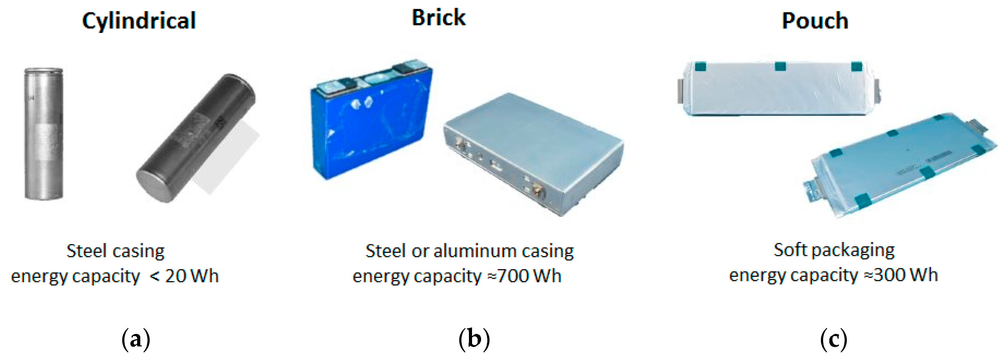
The main concerns regarding BEVs are currently associated with the battery pack, which is their energy storage medium. In recent decades, Li-ion batteries have become the preferred choice for BEVs thanks to their relatively high energy density and good durability [
3,
5,
10,
12]. In [
13], a comprehensive comparison of the different Li-ion technologies for battery solutions is reported. In [
14], the application of the Life Cycle Assessment (LCA) methodology to battery packs is presented and discussed as, in the perspective of environmental improvement, the transition to BEVs should not induce negative effects caused by the battery packs.
As the energy density of the battery pack is not comparable with one of the fuels, a relevant weight increase, a severe limitation in the driving range, and rather lengthy recharging operations are, at present, affecting BEVs. A trade-off is needed for the effective diffusion and usefulness of these vehicles [
5].
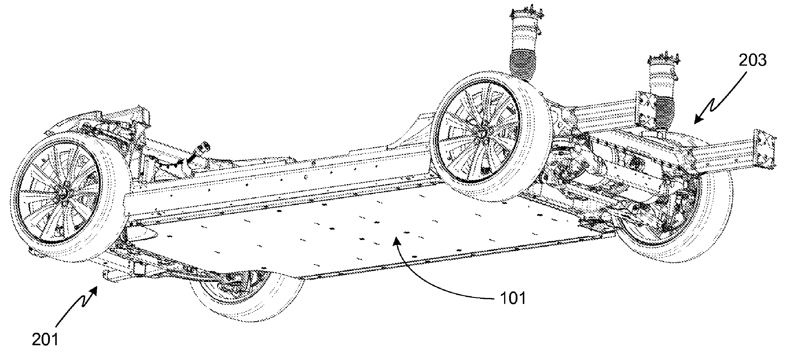
In this paper, our attention is focused on the architectural modifications that should be introduced into the car body to give a proper location to the battery pack. The required battery pack is no longer a simple, relatively cheap brick that will be located in the engine compartment, but it is a big, heavy, and expensive component to be located, managed, climatized, maintained, and protected. This paper intends to develop some engineering analyses and reviews by means of sketching out the possible solutions that have already been adopted for market vehicles. The location of the battery pack on board of the vehicle may affect the position of the vehicle center of gravity, which in turn could affect the vehicle’s drivability. In order to lower the possible negative consequences, the battery housing is generally located below the passengers compartment floor. This solution is also one of the most interesting in terms of battery pack protection in case of a lateral impact and for easy serviceability and maintenance. The integration of the battery pack’s housing structure and the vehicle floor leads to a sort of sandwich structure that could have beneficial effects on the body’s stiffness (both torsional and bending) and on the acoustical performance of the passenger compartment (better insulation).
The structural problems have already been considered in the published literature. Luttenbeger and co-workers [
15] developed a study concerning the safety behavior of a battery pack in case of impact. They have considered both the frontal impact and the pole side impact according to EuroNCAP standards. The battery housing is integrated into the pre-existing body in white. They have hypothesized some lateral impact energy absorbers to be applied around the battery pack enclosures. Arora and co-workers [
16] have developed a study related to the battery packaging design aimed to maximize its reliability and mitigate the safety risks in case of impact. They pay particular attention to the side impact but without developing a simulation analysis of the sketched solutions. Furthermore, the problem of the battery pack’s placement is considered, and some design guidelines are proposed. Kukrejia and co-workers [
17] have developed a study concerning the battery pack’s structure to enhance its damage-tolerant features, with particular reference to a possible frontal impact situation. Setiawan and Salim [
18] have developed a specific analysis of the side impact test against a pole according to the EuroNCAP standard. In particular, they have considered two structural modifications: either a metallic foam or a honeycomb inserted into the hollow thin-walled rocker in order to enhance its lateral compression strength or a contour of thin-walled tubes to be placed around the battery pack enclosure as an energy-absorber device. Hao and co-workers [
19] have developed a base study through the FE simulation of the behavior of the battery pack in case of a frontal impact. The 110 kg battery pack is placed in the front compartment under the hood and this justifies why they have concentrated their attention on the front impact event. Shui and co-workers [
20] have developed a study on the battery pack enclosure through a design optimization methodology aimed to optimize some of the relevant features of its mechanical design. In particular, they have considered the minimization of mass, the maximization of minimum natural frequency, and the minimization of maximum deformation as objective functions. Navale and co-workers [
21] have developed a study concerning the impact behavior of EV derived through a conversion process from a conventional vehicle. Some different cases of impact including side and pole side impact are considered. The flat battery pack and its control module are placed under the floor. To achieve an acceptable result, some modifications are introduced in some structural elements, including the floor cross-members. Furthermore, some special energy-absorbing structures are added for the door sills. In a very recent study, Pan and co-workers [
22] concentrated their attention on the impact behavior of the battery pack as a component that, equipping an EV vehicle, is submitted to dangerous acceleration in case of impact. Different materials and sheet thicknesses are considered to increase the protection offered by the enclosure to the battery pack. Mortazavi Moghaddam and co-workers [
23] have recently developed an analysis of an EV in case of a side pole impact as the severe load case according to ENCAP. Protection of the battery pack is improved by implementing a novel energy-absorber element into the body sill side that consists of a set of transverse conical corrugated tubes made of steel.
From the above review, the relevance of the safety problem of the EVs is clear, with particular attention to the lateral pole impact, which is more severe with respect to the lateral barrier impact. To protect the battery pack in case of impact, the above mentioned papers propose either the reinforcement of the vehicle’s lateral structure (the lateral rockers or the door sills) or the addition of a sacrificial structure around the battery enclosure. None of the mentioned papers develop the idea that the protection of the battery pack is the result of the properly conceived design of the battery pack enclosure together with (in relation to) the vehicle’s underbody structure (mainly the lateral rockers and the floor). This paper proposes some architectural considerations and presents some simulation results that offer evidence concerning how the interplay of the two mentioned structures is fundamental and gives some guidelines toward a collaborative design.
3. Approaches in the Crashworthiness Design
One of the challenging problems to be studied in the design phase of the described new architectural solutions for BEVs is the passive safety, with particular reference to the side impact. The side impact is not only the second type of statistical relevance in the road accident data analysis, but it is of top relevance with particular reference to the considered architecture and the concerns about possible damages of the battery pack [
22,
26].
The side impact suffers because of the very small space that is present in the body in the white structure where a structural device could be located with the aim of absorbing the side impact energy.
It is well known that in case of a side impact, two main test conditions are taken into account: one is related to the possible impact against another vehicle, the other one is related to the possible impact against a pole (or something similar, such as a tree). This last condition is particularly severe because the loads are concentrated in a smaller part of the body in white, compared to the first test condition, where a large part of the vehicle’s side structure is involved. This type of impact test is even more relevant for BEVs and targets that are even more stringent than in the case of traditional ICE vehicles, because of the battery pack. As already introduced, the battery pack is typically positioned in the underfloor, and it cannot be deformed in any way due to the above mentioned hazard of fire and explosion.
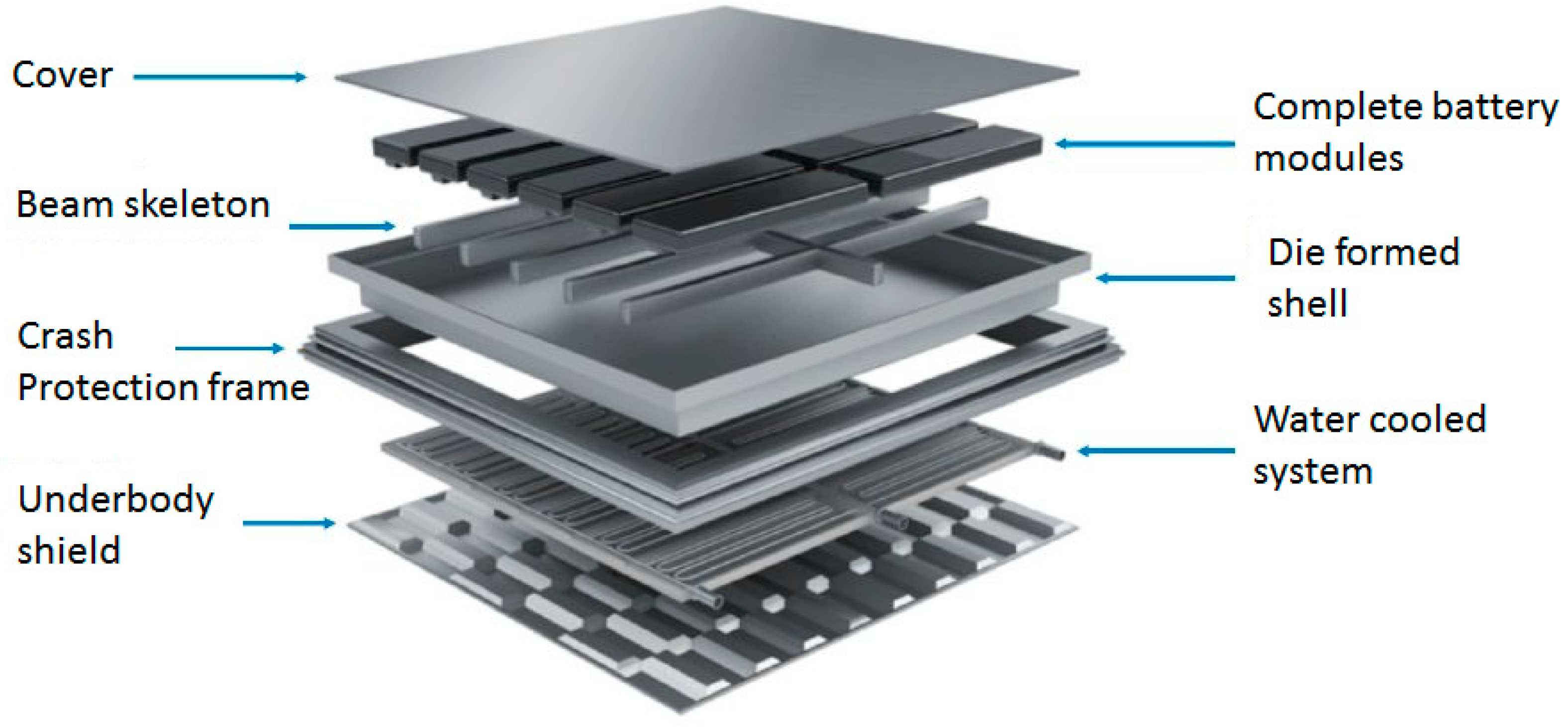
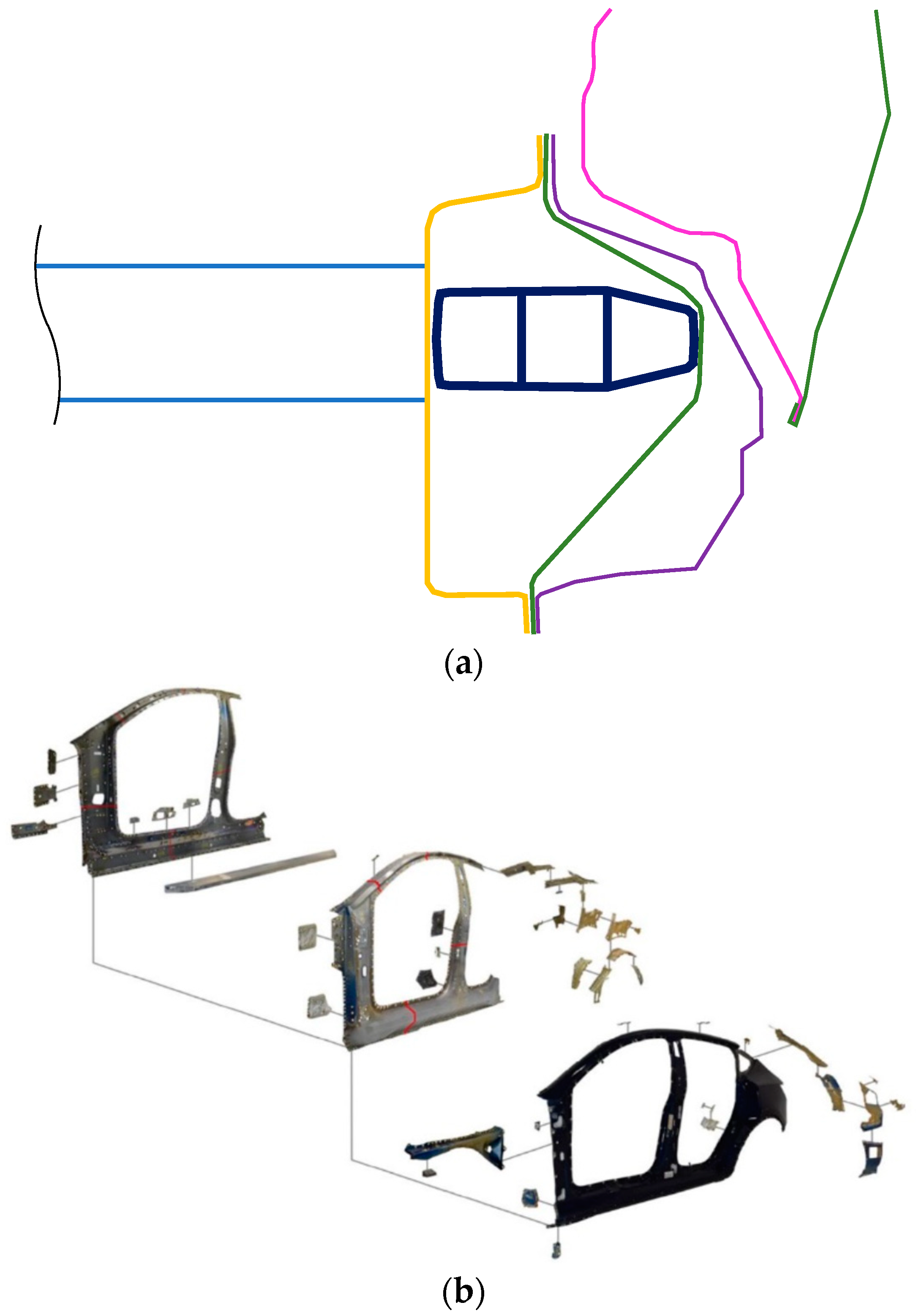
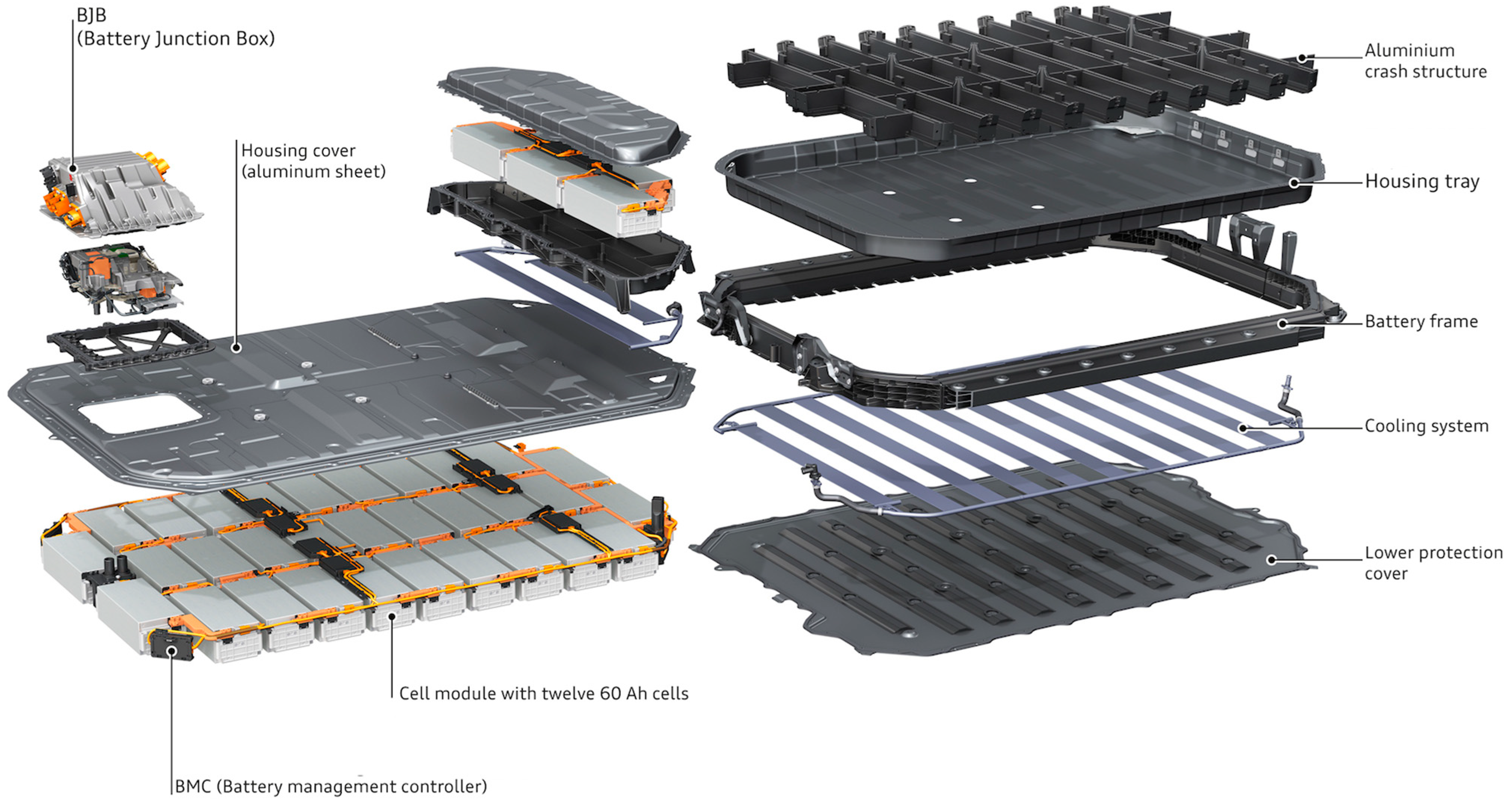
In these impact situations, the deck is the part of the body in white structure that is mainly involved. Some smaller contributions to the energy absorption in case of a side impact come from the B-pillar and from the door structure. The main contribution comes from the deck; therefore, the deck design had the priority. One essential component is the rocker, i.e., the lower longitudinal side member, which is typically a thin-walled, closed-section beam. Another important contribution comes from the sandwich structure, which is constituted by the passenger compartment floor and the underbody shield; sometimes, but not in all the existing solutions, the battery pack structure gives a contribution (see
Figure 2) through specific structural components that are part of the battery case.
In order to match the peculiar requirements for BEVs, the rocker should be stiffer and stronger than the usual one. A typical design solution used in BEVs has already been described in
Section 2.5 and it includes an extruded profile that is positioned inside the rocker, as shown in
Figure 9A–C. The section and the material of this added extruded profile change from one vehicle to another according to the adopted design philosophy.
The choice of the geometry of the extruded profile, of its wall thickness and material is very influential on the global behavior; therefore, these parameters must be optimized to achieve an excellent design. This results from a careful analysis of how the geometry, the position, and the shape of the extruded profile influence, for example, the lateral load distribution on the different parts of the underbody: the upper floor, lower floor, or battery case.
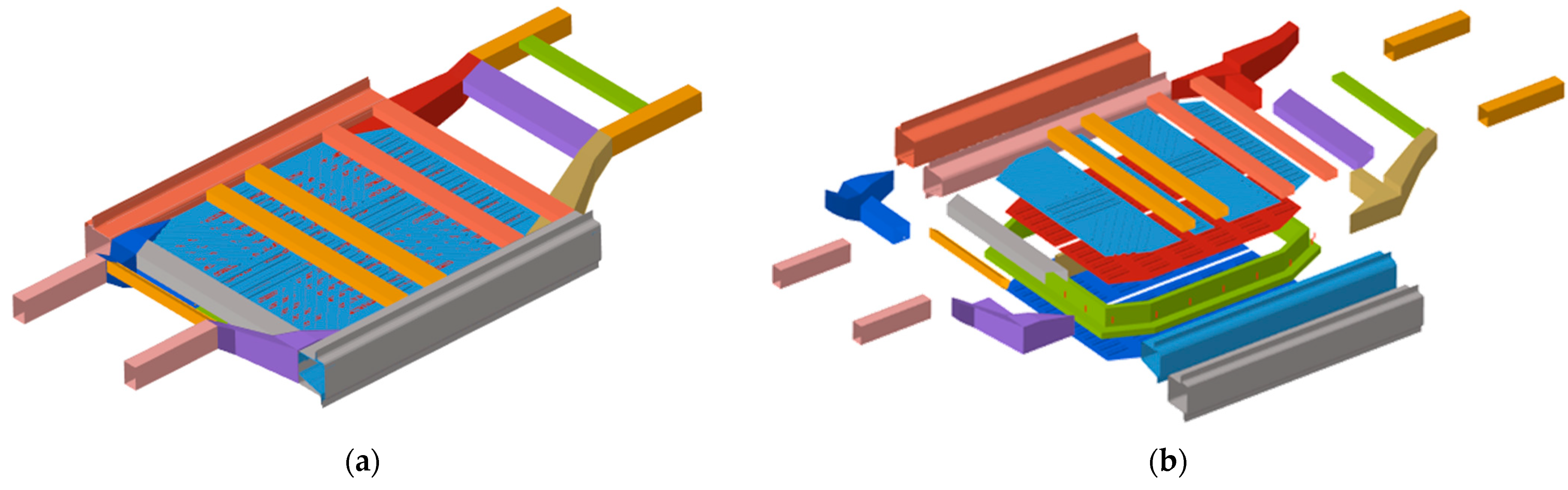
A detailed design of the structural solution is made by means of a Finite Element (FE) simulation. To this aim, the authors investigated the influence of the above mentioned parameters of the rocker by means of the simplified FE model shown in
Figure 11. It is a simplified generic model of the underbody for a low market segment of BEVs. It can be labeled a “generic” model because the geometries and the geometrical dimensions are not specific to a real vehicle. However, as it is possible to see in the exploded view of
Figure 11b, the simplified model is made up of the main underbody components that are present in a real vehicle. All these components were simulated with shell elements. Because the target of the developed analysis is to point out the influence of the rocker cross-sections, all the components were simulated with a simple bi-linear material model representing the typical steel/aluminum used for these applications. In particular, the material parameters were defined as the average values of what is currently present in the real solutions. A benchmarking analysis enabled the definition of the yield value of 500 MPa for the steel rocker components, 270 MPa for the aluminum rocker-extruded profiles, and 280 MPa for all the other components in the model. The end cross-sections of the longitudinal rail members in the front and rear (pink and yellow components in
Figure 11, respectively) are connected in a rigid way to two nodes positioned on the longitudinal x axis of the vehicle. The appropriate values of the mass and inertia were applied to these nodes in order to account for the other parts of the vehicle that were not present in the model and, therefore, to achieve the real behavior of the underbody. The parameters (geometries, dimensions, masses, and inertias) of this model were defined after a careful benchmarking analysis on the BEV vehicles on the market. With reference to a small car (B segment), the values of the masses were defined in 690 kg and 310 kg for the front and rear parts, respectively. To perform the study, the FE model was subjected to the side impact with the pole, according to the EuroNCAP regulations. Therefore, the impact angle between the longitudinal vehicle centerline and the pole velocity was set to 75°, whereas the initial velocity of the pole was set to 32 km/h [
32]. During the simulated test, the deformations, the forces transmitted, and the energies absorbed by the different components were measured and recorded. The deformations were measured as the compression of spring elements positioned along the transverse axis of the vehicle at the impact point considering their longitudinal position. The forces were measured with the cross-sections positioned as the spring elements. The energies absorbed by the different components were measured as the internal energy in the simulation.
The influence of the geometry of the extruded profile inserted into the rocker is highlighted in
Figure 12a, where the time history of the energy absorbed by the battery case is shown for three different rocker solutions studied in the work. The cross-sections of the rocker used in these considered solutions are shown in the figure. These three solutions are representative of the possible solutions that are present in the market. The solution with the black border in
Figure 12a is a traditional solution, whereby the rocker is reinforced with an internal septum in stamped steel sheets. In the other two cross-sections, the rocker is reinforced with an extruded profile made of aluminum. In the green border solution, the extruded profile fills all the cross-section, whereas in the blue border solution, the extruded profile is localized in a part of the cross-section. A smaller value of the energy to be absorbed by the battery case means better energy absorption by the rocker. The influence of the position of the aluminum-extruded profile on the value of impact lateral loads can be deduced from
Figure 12b, where the time history of the load, separately on the floor and on the battery pack, is reported for two different rocker reinforcement solutions. In this case, the traditional solution that is completely made of stamped steel sheets was not considered because it was outside the scope of the analysis. The cross-sections of the rocker used in these two considered solutions are shown in the figure. Once again, a smaller value of the force applied to the battery pack means a better solution.
On the other hand, it is of interest to analyze the effect of changes in the wall thicknesses of the extruded profile because, if their values are too high, the stiffness of this part will be too high compared with the nearer components and it will not deform (thus it will not absorb energy) or deform slightly (thus, it will absorb a little amount of energy) during the impact. In
Figure 13a, the time histories of the impact deformation of the rocker are reported for the same internal reinforcement solution but with two different wall thicknesses. As a consequence of a too stiff solution, all the loads will be rigidly transmitted to the battery pack (
Figure 13b). This is not what the structural designer desires to achieve, as this will probably result in relevant damage to the battery pack.
As a conclusion of this part of the study, the interplay between the compressive stiffness of the vehicle’s lateral structure (and in particular, of the rocker and its internal reinforcing structure) with the lateral stiffness of the battery case is evident. When the internal reinforcement is not occupying the whole section of the rocker, it is important to properly select its location and eventual clearance.
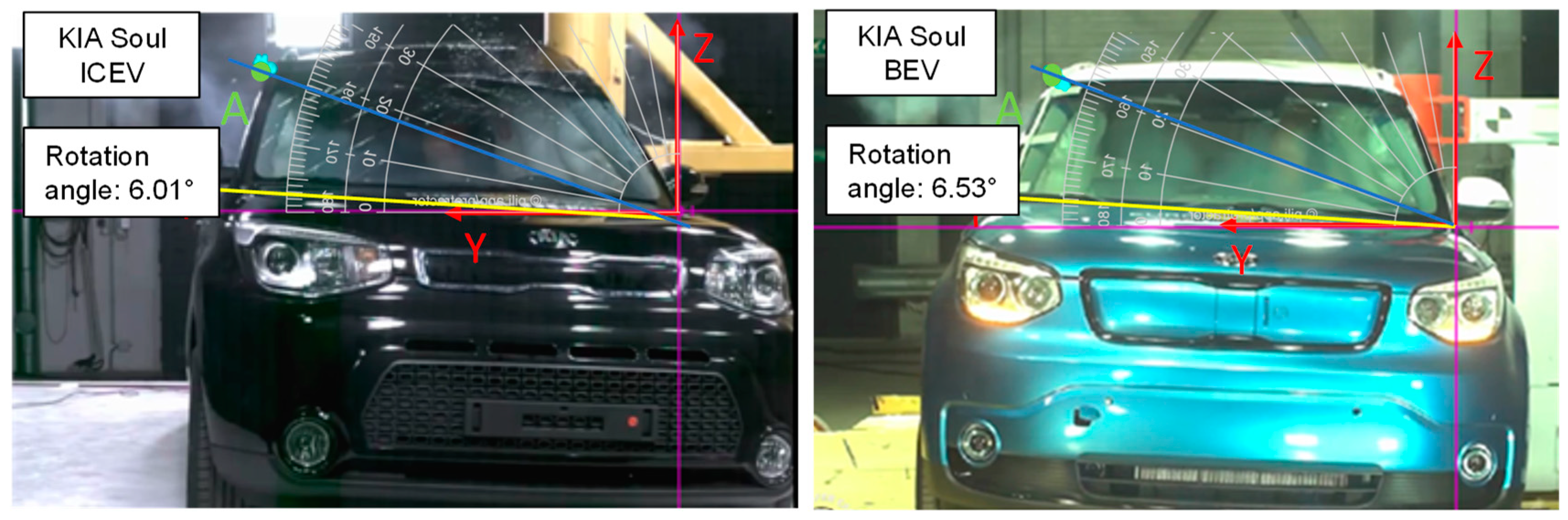
As a consequence of the changes in the structure, the global dynamic behavior of BEVs during a side crash is different with respect to the usual ICEVs. Being the lower longitudinal member stiffer, the vehicle tends to have a higher rolling rotation around the longitudinal axis, because there is less deformation of the lower structure, as it is possible to see in
Figure 14, where the responses of the same vehicle equipped either with a traditional internal combustion engine or with an electrical powertrain and submitted to the pole impact test are compared. Consequently, the upper part of the BEV structure (in particular the B-pillar and the upper beam that constitute the roof longitudinal member) is involved in the impact, making contact with the pole.
4. Conclusions
The evolution toward electric vehicles nowadays appears to be the main stream in the automotive and transportation industries. This choice is expected to have a beneficial impact on climate change and on the pollution of the air, especially inside our towns; however, as discussed in this paper, it is really challenging to develop feasible, effective solutions to relevant problems in the BEV design.
This innovative type of vehicle, equipped with an electrical powertrain system and related specific controls, may have an insufficient autonomy problem. A solution for this is given by strong increments of the dimension and capacity of the on-board battery pack and through the development of technologies to dramatically increase the rapidity of battery recharging operations.
Our attention has been focused on the architectural modifications that should be introduced into the car body to give a proper location to the battery pack. The required battery pack is no longer a simple, relatively cheap brick to be located in the engine compartment, but it is a big, heavy, and expensive component to be located, managed, climatized, maintained, and protected.
After a detailed overview of the published literature on the specific subject, we presented some engineering analyses together with an overview of sketches of some possible solutions for the above-listed points.
Taking into account the weight of the battery pack required for new BEVs, in order to avoid a relevant change in the location of the vehicle center of gravity that in turn could affect the vehicle’s drivability, it is generally accepted that the battery housing should be located below the passenger compartment floor. This solution is very interesting from the point of view of the battery pack’s protection in case of a front, lateral, or rear impact and for easy serviceability and maintenance.
The integration of the battery pack housing structure and of the vehicle floor leads to a sort of sandwich structure that could have beneficial effects on the body’s stiffness (both torsional and bending).
This paper proposes some considerations related to the impact protection of the battery pack, with particular reference to the side impacts against another vehicle and against a fixed obstacle, such as a pole, which demonstrate themselves to be the most critical condition. Three different solutions for the reinforcement of the lateral rocker are considered. One consists of a traditional internal septum, and the other two consist of extruded profiles inserted inside the rocker. The reported results of the FE analysis, carried out with a simplified model, demonstrate the effectiveness of the different possible solutions for reinforcement placed inside the rocker, and the importance of the proper choice of wall thickness in the interplay among the different parts of the vehicle side structure and battery case structure.


