1. Introduction
Autonomous vehicles (AV) will drastically transform human and goods transportation and enable urban areas to be redesigned, creating more liveable and enjoyable spaces, thus meeting several demands simultaneously. The cost of transportation is reduced by removing the driver from the control loop. Efficiency is enhanced by integrating communication and intelligent algorithms to improve the flow of traffic. Safety is increased because AVs, unlike human drivers, are not prone to fatigue-induced errors, distractions, drowsiness, etc. [
1]. In addition, AVs offer greater comfort due to their accuracy and adaptivity in motion control.
In turn, AVs contribute to tackling many socio-economic challenges, such as narrowing the equality gap. With reduced transportation costs, AVs enable private mobility for each individual; car ownership also declines, which will potentially lead to minimising the number of vehicles on the road. In addition, AVs can be operated continually, thereby leaving certain areas free throughout the day [
2,
3].
However, despite the great number of advantages, the development of autonomous transportation is experiencing serious challenges, limiting its practical application. Many technological and infrastructural bottlenecks, as well as governmental policies, are restricting the advancement of AVs. Nevertheless, from a technological perspective, scholars around the world are working alongside major vehicle manufacturers to make AVs a reality and integrate them into everyday life. The fruit of one such industry–academy collaboration is presented in this paper.
The most efficient way of bringing AVs to the road is through gradual automation, rather than developing full autonomy from the outset. This means the first AVs being partly or conditionally automated, i.e., levels 2 to 3 in the AV automation classification [
4]. The first commercial AVs can handle individual tasks, such as parking and overtaking and driving on the highway. This entails a human driver remaining in the loop as a supervisor and observer who must be ready to assume control of the vehicle at any time. These autonomous driving functions are being rapidly researched and developed today. Eventually, these individual automated functions will merge in a unified system, ultimately enabling full autonomous mobility, corresponding to levels 4 and 5, where human input into controlling the vehicle will not be required [
4].
One such automated driving function, the Autonomous Parking System (APS), is designed to perform automated parking. The system automatically searches the environment adjacent to the vehicle for suitable parking slots between vehicles or road markings, such as painted lines, evaluates the information required to calculate parking trajectories, and sends steering and throttle/braking commands to an electronic interface in the control systems for lateral and longitudinal control of the vehicle. Its goal is to liberate humans from one of the most tedious and stressful tasks of driving, and to make these manoeuvres safer by avoiding numerous potential collisions. Not only does APS contribute to enhancing the parking infrastructure in general by creating more liveable space in urban areas, it also saves drivers a substantial amount of time usually spent having to search for a parking space, and decreases the burden of traffic jams, which cause frustration, monetary losses, and unnecessary pollution [
5].
This paper is dedicated to APS development and experimental, on-street testing under real-world traffic conditions. Communication technology, connecting AVs, the parking infrastructure, and end-users (i.e., drivers) based on Message Queuing Telemetry Transport (MQTT) [
6] is introduced. Various human–machine interface (HMI) concepts for vehicle communication with human drivers via mobile devices, webpages, and cockpit control panels are proposed and illustrated. A methodology for on-street APS testing under real-world traffic conditions, which includes parallel and perpendicular parking manoeuvres and also indicates clear requirements and safety triggers, is established. In addition, an experimental scenario is elaborated. Finally, a case study with an electric vehicle platform in an urban environment is presented, which also outlines the limitation of the current conceptual system.
The paper is set out as follows: the next subsection places this work in the context of the existing literature.
Section 2 is dedicated to describing the communication system. In
Section 3, the HMI concepts for various communication technologies are discussed. A testing methodology is described in
Section 4. A case study with an electric vehicle prototype is presented in
Section 5. Finally, the research is concluded and discussed in
Section 6.
Related Works
Several patents have been granted for multiple inventions related to APS. The works are dated from the 1990s to the present. Czekaj [
7] proposed a semi-APS that calculated the current position, as well as the trajectory required to accomplish the parking manoeuvre, by utilising vehicle position measurements. It also provides tactile feedback to the vehicle operator. Moshchuk et al. [
8] developed a method of guiding a vehicle to a region to initiate a parallel parking manoeuvre. A system and method for using gestures in APS were described in [
9]. An approach for transferring a command to activate the APS procedure using a communication link between an operator located outside the vehicle and the vehicle itself was developed in [
10]. Finally, a method for operating a driver assistance system to perform an APS manoeuvre was presented in [
11].
Paromtchik and Laugier [
12] proposed a practical approach to generating and controlling motion for a nonholonomic vehicle to parallel park autonomously based on range measurements to environmental objects around the vehicle. Using ultrasonic sensors, another parallel parking APS was described in [
13]. A computational-intelligence-based APS, implemented using neuro-fuzzy architecture capable of detecting parking slots and performing reverse parking manoeuvres on various types of roads, was built in [
14]. Another artificial-intelligence-based eco-friendly APS—which used hybrid robotic valets in smart parking, helped to optimise parking space usage, and incorporated reinforcement learning to achieve high performance—was proposed in [
15]. Recently, fuzzy logic was also applied to autonomous vehicle parking [
16].
Jang et al. [
17] introduced a re-plannable APS with a stand-alone around-view monitor. The proposed system can continuously reflect several errors and risks of perception, positioning, and control in real-life situations, and then re-generate the parking trajectory to improve parking precision and avoid collisions. Wu et al. [
18] and Zhang et al. [
19] introduced compact automated parking concepts. The first involves the system having a rotating ring equipped with shuttles in each tier for horizontal transport. The latter work investigated a tower-based APS, which can simultaneously implement two types of movement—ascending/descending in the vertical direction and rotating counter-clockwise/clockwise. At present, these designs are rarely seen in cities, yet they represent promising solutions for transforming urban areas into liveable spaces in the future.
Connectivity is central to the success of APS, especially in urban environments where vehicular networks are characterised by high mobility and dynamic topology [
20]. Chippalkatti et al. [
21] described a system based on the Internet of Things (IoT) that monitors empty parking spaces in real time, not only saving drivers time but also eliminating frustration. A smart parking system, suitable for both indoor and outdoor use and which is based on Bluetooth low-energy beacons and uses particle filtering to improve its accuracy, was introduced in [
22]. Shahzad et al. [
23] developed a smart system capable of managing a massive crowd of vehicles during parking.
Some of the major cybersecurity threats arising in the world of connected cars are discussed in [
24]. This work focuses on three important areas most susceptible to cyberattacks—e-mobility, car sharing, and automated valet parking. The authors also mention available models that help to protect connected vehicles. A new privacy-preserving reservation scheme for securing APS was developed in [
25], which is based on the following policy: each anonymous user may only have one valid reservation token at any given moment, and the token can only be used to book one vacant parking space once. Furthermore, communication via vehicle-to-infrastructure and model predictive control functionality distributed among multiple vehicles and infrastructures was studied in [
26]. In this context, cooperative automated valet parking was examined in [
27], where the authors proposed a solution involving multi-agent pathfinding.
Lastly, as a human driver is not expected to be present inside an AV operating in APS mode, HMI is of great importance in the overall loop. This is true, for instance, for people with visual impairments, increasing trust in self-driving vehicular technology, encouraging belief in its likely usability, motivating people to purchase it, and reducing fear of operational failures [
28]. HMIs for people living with disabilities have been verified internally and are out of the scope of this research.
In [
29], two conceptual external HMIs were presented to display the vehicle’s manoeuvring intentions with respect to pedestrians. With another goal to improve the safety of transportation systems, the authors in [
30] showed that multimodal HMIs significantly reduced driver workload, improved the efficiency of the interaction, and minimised input errors compared to unimodal HMIs. In [
31], the colours white and turquoise for external HMI lamps—indicating that the automated driving system is engaged—were compared for safety-critical deployment.
Most of the examined works have one thing in common—they focus on one single element in the whole APS software and communication stack. Hence, most of their functionality is not directly applicable to a real vehicle platform, because it is not clear how these individual systems can be integrated into each other or coexist under real-world conditions.
This paper, however, offers a unique contribution in that the full APS pipeline is elaborated and experimentally validated. The starting point is the communication framework between the system’s clients—vehicle, end-user/driver, and parking infrastructure. How the clients interact among various devices via the HMI (i.e., different HMI technologies) is then presented. A methodology to comprehensively test the software stack in a real vehicle demonstrator is introduced. Finally, the APS is verified in a real-world environment with an electric vehicle prototype operating in real traffic conditions using real-time connectivity. The robotic sub-systems, namely perception, localisation, decision making [
32], etc., are out of the scope of this paper.
2. Communication System
2.1. General Framework
The communication system is the core element of the AV software stack. It enables data to be transferred among the AV, parking infrastructure, and driver (e.g., via a mobile application, webpage, etc.) in real-time, without the driver needing to be inside the AV. The main interaction with the system is performed remotely. The communication concept among the AV, mobile device, and parking facility is described in detail in this section.
The information is exchanged with individual sub-systems of the APS. These data may contain individual preferences, time, reserved parking space, payment, location, and others. This transfer of information and the appropriate response from the various components of the communication system must be reliable. The shared information also contains an input of intention from the driver to carry out a specific action.
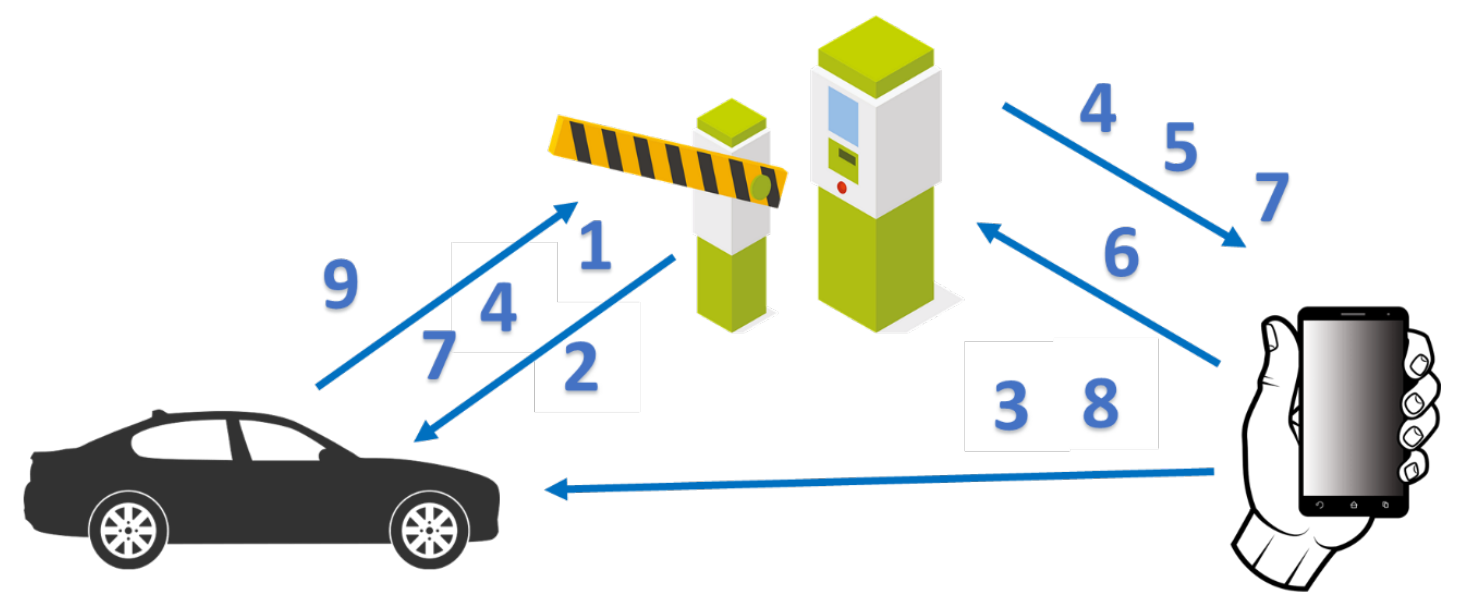
A simplified communication diagram is introduced in
Figure 1. It comprises the three main clients—the AV, parking facility, and driver (via mobile device). The communication procedure can be divided into individual steps with respect to communication (outlined in
Figure 1):
Communication between AV and parking facility: The AV connects to the parking facility and requests that the parking procedure be accepted;
Communication between parking facility and AV: The parking infrastructure looks for an available parking space and confirms the availability of spaces to the AV;
Communication between driver and AV: The driver exits the AV and initiates the automated parking manoeuvre (i.e., via key or mobile application);
Communication between AV, parking facility, and AV; and between parking facility and mobile device: The AV automatically pulls up to the parking drop-off zone (if not already located at the drop-off zone) and goes on to be parked by the parking infrastructure;
Communication between parking facility and driver: Confirmation of successful parking procedure;
Communication between driver and parking facility: Request for parking termination;
Communication between parking facility, AV, and parking facility; and between parking facility and driver: The AV is driven by the parking infrastructure via the automated vehicle systems. The parking facility tracks the progress and updates the driver on the process;
Communication between driver and AV: The driver unlocks the AV and assumes control of the AV;
Communication between AV and parking facility: End of communication. The vehicle is in manual control mode.
The proposed communication scheme may be slightly modified to comply with user requirements. It can also be expanded. In addition, the communication mechanism can be modified to perform similar communication tasks. The presented communication scheme only represents a basic functional concept, leading directly to the requested process. In real-world situations, there are many other control processes and security checks included in this sequence as a parallel process.
One significant requirement is that the state of the process must be seen by all clients involved in the manoeuvre. This can be guaranteed by the permanent intercommunication among all clients, which must be established and maintained via the client–server communication system.
2.2. Message Queuing Telemetry Transport Protocol
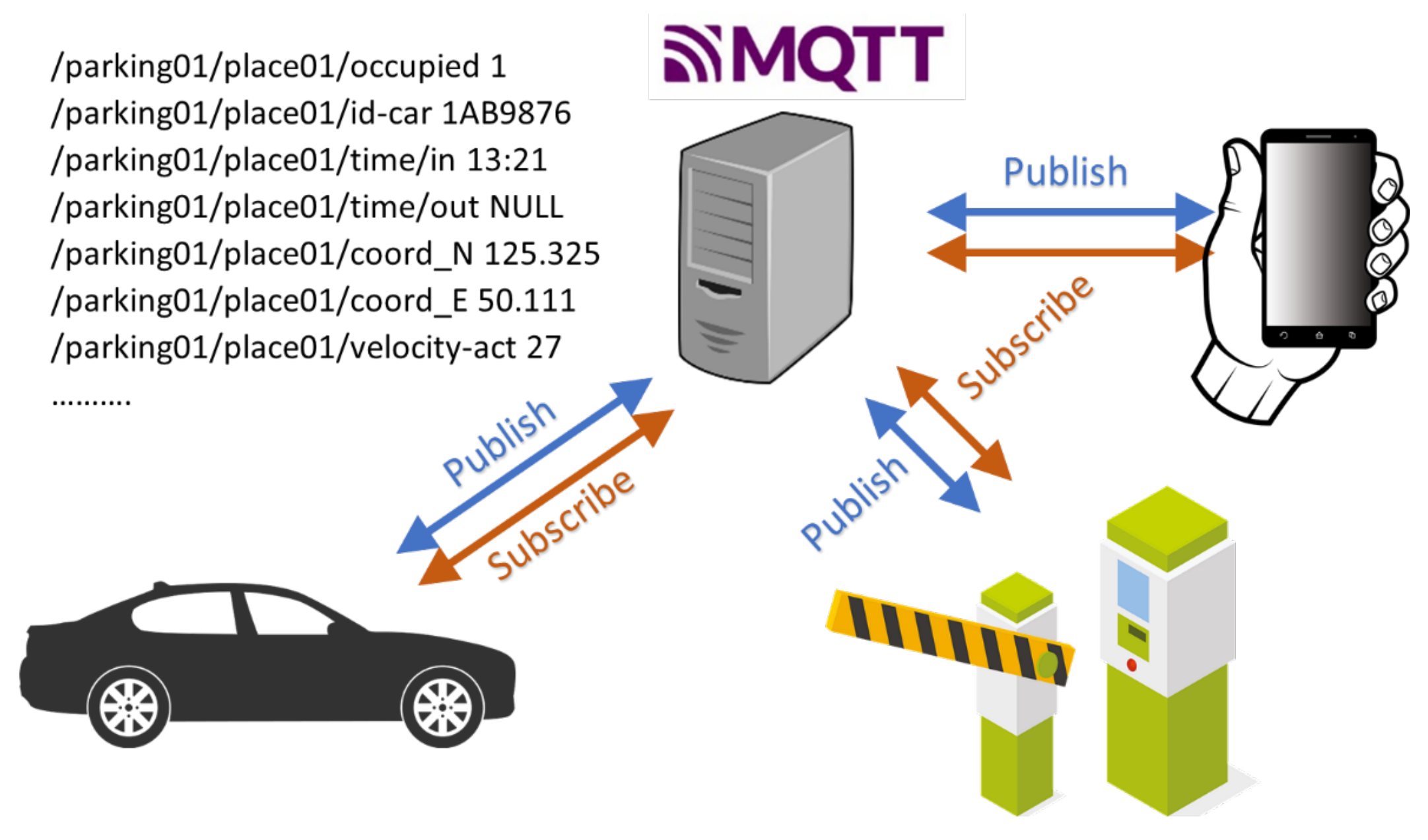
The MQTT protocol is selected to serve as the basis for communication and data exchange. The MQTT topology for the AV–parking facility–driver system is presented in
Figure 2. MQTT allows clients to publish data on the server, similar to a noticeboard, and to receive their subscribed subsets almost immediately after they are published [
33]. The mosquito MQTT server [
34] is used as the test platform. The MQTT protocol is widely supported by coding languages as proprietary devices, mainly from the IoT community. The MQTT server is also often called a “pub/sub broker”, and its main duty is to supervise the interaction between publisher and subscriber. This solution is beneficial when the system has a number of publishers and subscribers simultaneously, while the publishers do not need to know which of the stackholders is receiving the information. The sub/pub broker is only concerned about the correct message being delivered to the correct subscriber. The MQTT protocol is centralised, making the whole communication system centralised, too.
The clear benefits of using MQTT communication principles (
Figure 3) are outlined below:
Every message in the MQTT comprises two parts—the topic and the message;
The topic is a hierarchically created structure, which directly points to the individual message. The length of the actual topic string is a maximum of 65,536 bytes. For instance, the topic /CZ/Prague/Parking_UTIA/parking01/place01/time/in specifies the name of the state, name of the city, place in the city, the exact car park, parking space number, time values, and time of arrival;
The message for the topic is any string limited to 268,435,456 bytes. For the topic above, it could be the time of arrival, for example,
”13:21” (
Figure 2);
The publisher is the client that publishes information on the server;
The subscriber is the client that receives a requested digest of topics and messages;
Any device or system (e.g., mobile device, AV, parking facility) can serve as a publisher and subscriber simultaneously;
Every message has a defined Quality of Service (QoS) flag for delivery: QoS0—at most once (fire and forget), QoS1—at least once (acknowledged delivery), and QoS2—exactly once (assured delivery). The QoS level is set by the protocol itself and has the main influence on the network load and the response time;
Every message may have the flag ”retain”, which tells the broker that it is possible to send the subscriber the last known value of a message for the requested topic. For example, if the capacity of the battery is measured every minute and no retain flag is set, the subscriber must wait for up to 60 s to obtain the newly measured value. If the topic has the retain flag, the last known value is published to the client immediately.
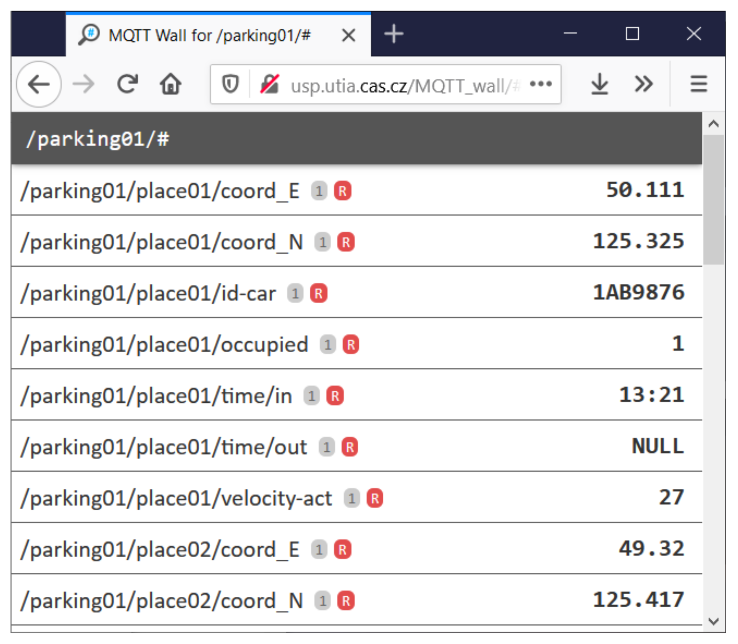
Remark 1. The MQTT server is relatively non-resource-intensive on hardware. For instance, the authors in [35] showed that, on an Intel i5/2.2 GHz processor with 8 GB RAM, the Eclipse Mosquitto™ server can handle up to 32,016 messages per second at the minimum QoS0, and 6585 messages per second at QoS2. A complete description of the MQTT protocol is established as an ISO standard—ISO/IEC 20922:2016. The MQTT wall [
36] is an application for visualising the MQTT state via an httpd server. It connects to the MQTT server using the WebSocket computer communications protocol. It dynamically shows the state of every subscribed topic and corresponding message. It also allows for messages to be filtered by the MQTT syntax.
2.3. Practical Communication Platform
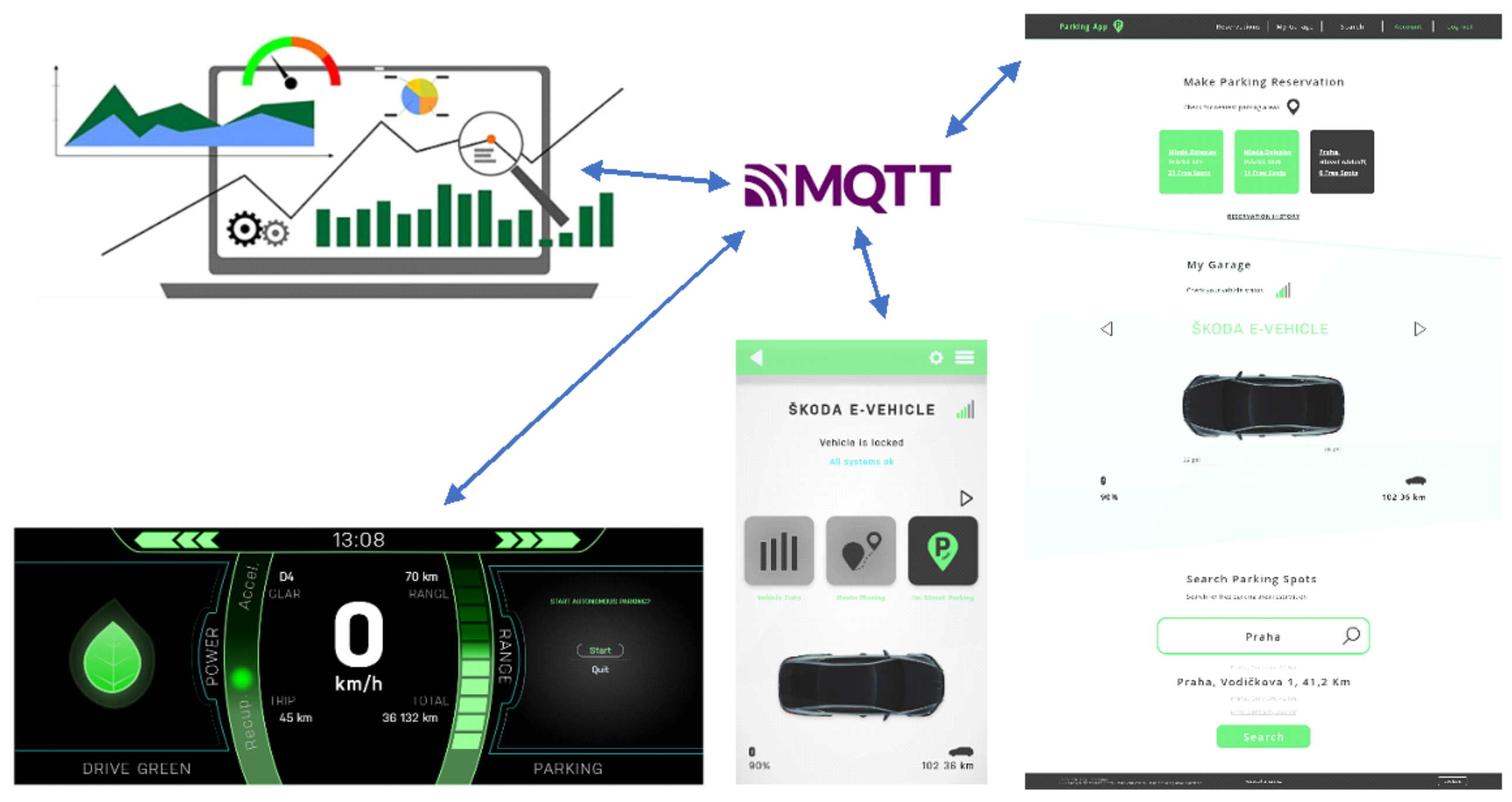
The practical implementation of the MQTT protocol (
Figure 4) depends on the specific software solution, which can vary among low-level programmed car software, mobile applications written, for example, in Java, and web or Android apps running on mobile software. The car, mobile, and web apps can be programmed independently; the monitoring centre does not require a direct connection to individual apps.
The MQTT server looks like an integration platform that gathers all the required information from all devices interacting in the parking process. Each device functions according to subscribed values that are obtained dynamically with minimum latency. The MQTT protocol is standardised and thus operates under the assumption that it is usable independently of programming techniques and should be supported by every IoT-certified device as a common standard.
Remark 2. In commercial apps, both authentication and authorisation must be considered.
3. Human–Machine Interface
Four HMI concepts have been developed in total—vehicle, web application, mobile application, and vehicle cockpit. All HMI systems are developed in C++. They can also be modified according to the user’s needs without requiring any knowledge of programming.
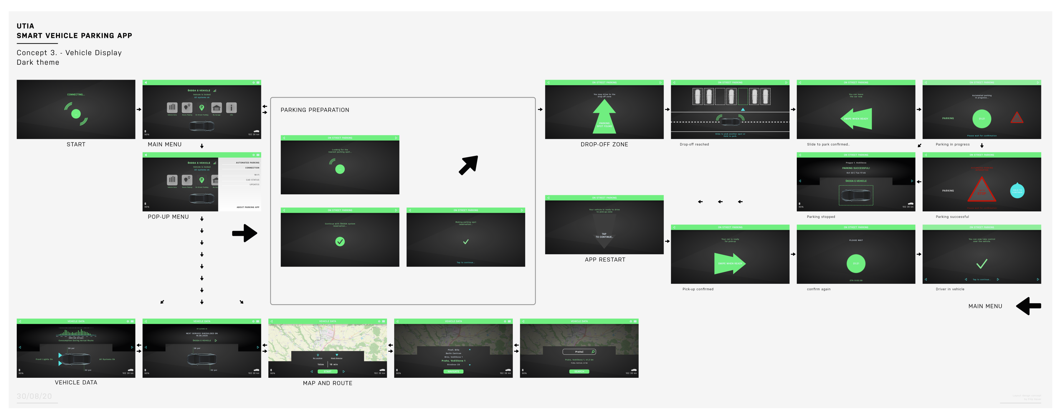
3.1. Vehicle Display HMI
The concept of the vehicle APS HMI is introduced in
Figure 5. It is depicted on the vehicle display to the right of the driver (i.e., for most vehicles operating in Europe). The HMI is designed to be intuitive and was verified in a comprehensive driver decoy study looking into minimising driver distraction. This technology is available to the ŠKODA AUTO research laboratory and was tested on numerous volunteers from young to elderly and with female and male drivers. The user activates the application via the touch screen display or a button on the multifunctional steering wheel. The display then flashes icons informing the user about the current environment, i.e., location, availability, etc. The next stage involves selecting parking preparation. This operation is successful once the parking facility has been scanned and an available parking space has been selected. The HMI informs the driver about the successful parking preparation.
The application also allows for vehicle data to be extracted. It interactively shows the symbolic representation of the environment in which the vehicle is operating. The environment is extracted from the AV’s perception sensors, and the concept is connected to the global map of the environment. Therefore, the user may find other available parking facilities within a reasonable radius, should parking at the selected area not be accepted by the communication system.
After successfully preparing for parking (i.e., request—confirmation), the AV is left at the drop-off zone, where the occupants are expected to exit the car. The autonomous navigation route to a selected parking space can be viewed from the display should the driver remain inside the cockpit. Upon arrival at the parking space, two possible states appear on the display—either a safe option for performing a manoeuvre or the detection of a hazard. If the latter is activated, the vehicle waits until it is safe for the manoeuvre to continue and the path is clear of other road users and static obstacles in the vicinity. The final display icon signals the end of the manoeuvre.
The next stage involves the HMI being restarted for the vehicle’s exit from the parking space. In principle, the described method is performed in reverse. After the user’s confirmation of assuming control of the vehicle, the HMI is switched to standby mode until the next request from the driver.
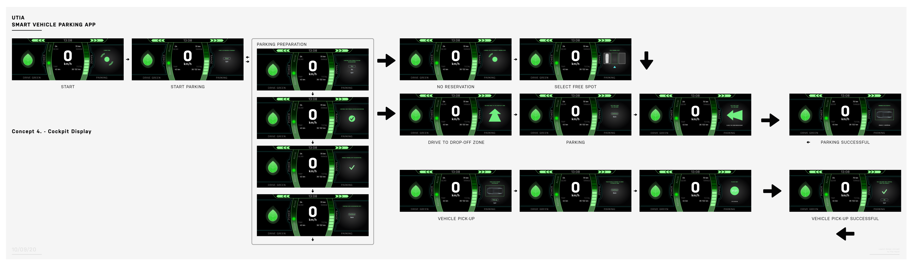
3.2. Vehicle Cockpit HMI
The vehicle cockpit HMI concept is presented in
Figure 6. While avoiding complexity in information delivery and minimising the potential for distraction, relevant information on the autonomous parking procedure is displayed on a screen behind the steering wheel. The icons are identical to those developed for the vehicle’s main onboard display.
Standard information remains available on the HMI. Among other things, it includes the vehicle’s current velocity, battery charge level, and recuperation potential if applicable. The user navigates through the icons via the switches around the steering wheel. To avoid overloading the driver with information, other parking facilities may not be displayed to the driver along with the area map.
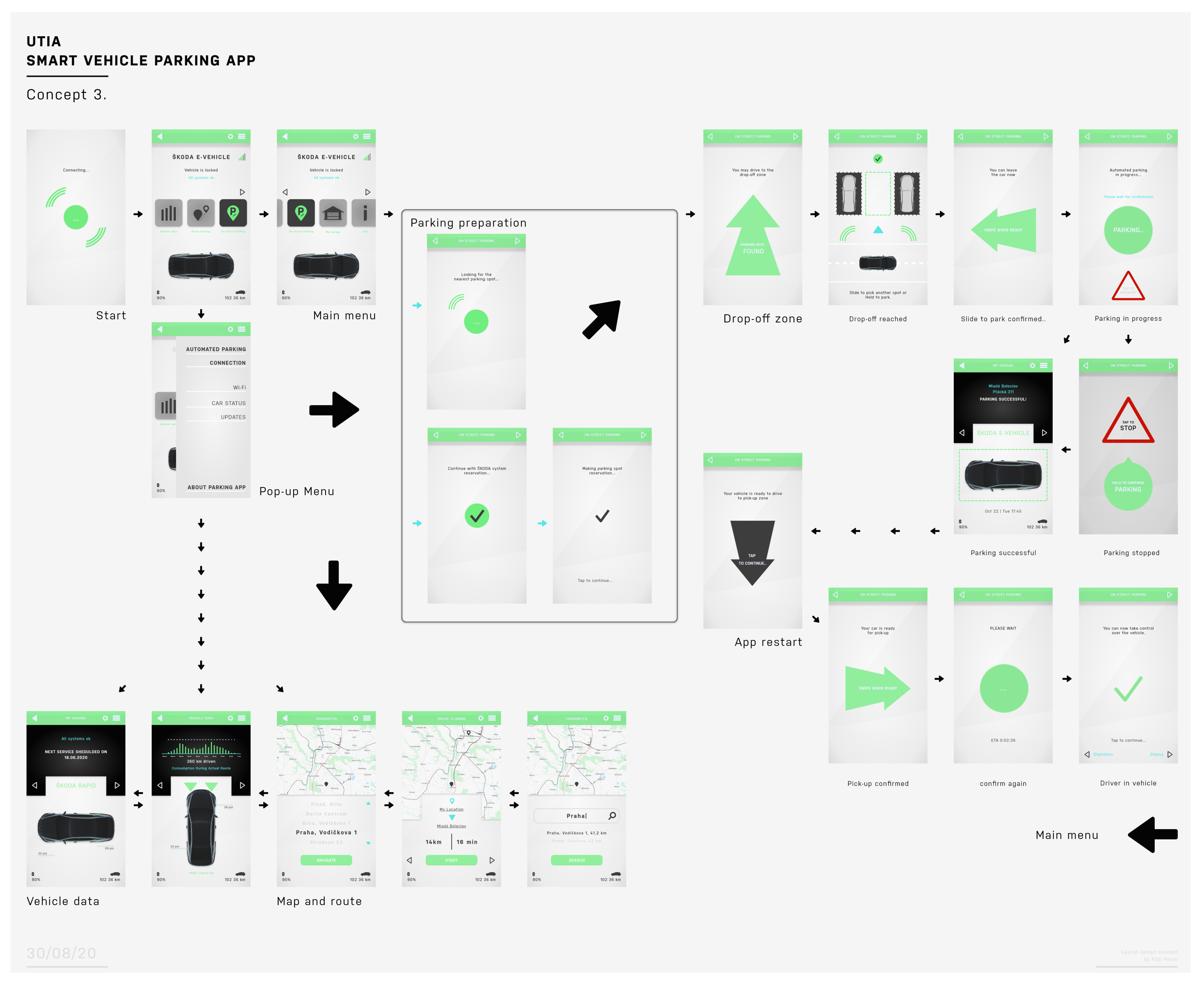
3.3. Smartphone HMI
The smartphone HMI concept is presented in
Figure 7. The process starts by activating the application. The user controls the functionality via a touch screen. The main menu displays the vehicle status to the user. From the main menu, the user can access additional information and parking locations as well as request autonomous parking to be activated.
The vehicle data, map, and routes can each be selected. The first gives information on the vehicle status, its active functions, etc.; the latter includes global environment information, for example, the distance to a selected parking facility, time to reach the location, reservation, payment, etc.
Once the autonomous parking function has been selected, the preparation window flashes. This phase involves the time spent connected to the parking infrastructure and the selected parking space, with the end-user being informed as to the current status through audible and visual signals.
The mobile application waits for the vehicle to arrive at the drop-off zone where the user may exit the vehicle. Next, the vehicle drives to the selected parking space. Once it arrives at the space, the user confirms the initiation of the parking manoeuvre via the application.
Next, the autonomous parking manoeuvre starts, and the user is informed by receiving the notification “Parking in progress”. In addition, the driver can cancel the operation should a hazard arise and the vehicle is unable to recognise it. The cancellation button is highlighted in a red triangle to draw attention to this area on the screen. Finally, if no termination is requested, the vehicle informs the driver that the parking manoeuvre has been completed successfully.
The driver presses a black arrow button on the screen when the car is to be recalled from the parking infrastructure. Then, the operation starts in reverse. The user confirms the request twice. The mobile application finishes once the recognised human is inside the vehicle cockpit.
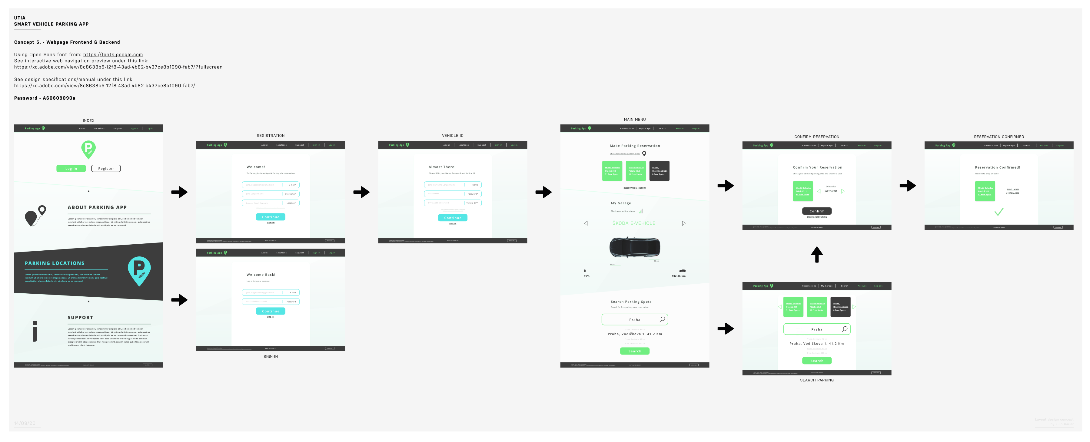
3.4. Web HMI
The final HMI concept is a web application (
Figure 8)—a webpage front- and backend. A user manual is also available along with online user support. What differentiates this part of the concept from other HMI solutions proposed in this paper is the requirement to pre-register a vehicle and log in.
Thanks to a larger memory capacity, the webpage is enhanced with several specific design features: the three main functions available on the welcome page are parking reservation, information about the vehicle, and a search engine for desired parking facilities. After selecting a parking option, the user confirms their reservation, after which they receive feedback confirming this reservation. An alternative path is to first select the parking space from the search engine. In this case, it can be reserved before arrival.
3.5. Concluding Remark
HMI technology plays a role in the communication between the driver and the AV; the system must be intuitive, easy to use, and understandable. An AV is a complex technology, which is why the user, who remains responsible for the vehicle operation, must be aware of each step the AV is taking. As shown in the concepts described in this paper, the information conveyed via the HMI must be comprehensive and easy to read. Technology acceptance is also addressed for a large scope of potential users. Minimal text is used in designing the HMI concepts. All major aspects are represented as figures or shape icons. Colour is also integral to the design, responsible for attracting attention and clarifying information. The design can be also modified to user preferences.
4. Methodology
The system has a strict validation methodology and must be capable of multitasking. The APS methodological functionality verification demands the desired manoeuvre be performed without systematic or functional errors.
The APS consists of non-contact sensors for environmental perception and a control algorithm. Once the manoeuvre has been confirmed (i.e., the decision has been made by the human driver or end-user), the APS starts by searching for a suitable parking space, then acquires information about the environment around the vehicle, calculates the trajectory, and finishes with the lateral and longitudinal control of the vehicle. The vehicle control is fully automated; however, the driver has the power to cancel the operation at any time for safety reasons. The APS also recognises obstacles and avoids collisions with them while manoeuvring into the parking slot. Robotic sub-systems are out of scope of this paper.
An APS-equipped vehicle supports both parallel and perpendicular parking equally well. It must also automatically select one or the other depending on the space available at the parking facility. An APS’ target slot is either a space between two vehicles or a space defined by road markings, such as painted lines. During the test, the driver must be able to assume control of the vehicle at any time.
4.1. System Requirements
During the methodology test experiment under real-world conditions, the following requirements for the system functionality are stipulated to ensure the maximum safety of its operation:
The recommended speed limit is (a) forward: 10 km/h, (b) reverse: 7–12 km/h. However, this speed limit must conform to local regulatory requirements, such as internal law and technical guidance;
The APS vehicle must automatically navigate to a selected parking space;
The APS must avoid collisions with any dynamic or stationary object while manoeuvring into or exiting a parking slot;
The driver must ensure that the parking slot has sufficient depth. This is essential to avoiding perception failures, which is currently under development;
The APS shall abort the automated parking procedure in the event of one or more of the following conditions:
- -
The driver assumes control or aborts the procedure, including remotely via the mobile application;
- -
The APS detects an internal system failure;
- -
The vehicle exceeds the speed limit for the autonomous parking procedure;
- -
Collision with any obstacle/obstruction;
- -
Connection to driver’s mobile device is lost;
The APS vehicle automatically recognises obstacles while manoeuvring into or exiting a parking slot;
If the system detects an unsafe condition, the manoeuvre must not be started or must be immediately aborted, and the driver will be informed about the APS vehicle state via the HMI, e.g., mobile application;
Drivers and passengers leave the APS vehicle before the automated APS is activated;
The APS vehicle informs the driver upon completing the manoeuvre via the HMI.
4.2. Control System
The control system is concerned with the optimal speed package tool. This tool is created to find optimal driving profiles for a car driving along a known path from point A to point B with a certain gain function. This function can take various forms and ensures the weighted optimisation of two contradicting criteria: the passage of time and traffic rules. The goal is to provide an optimal leading speed and acceleration/deceleration signals to maximise gains (i.e., minimum losses in terms of time spent and energy consumption).
The approach to achieving the above-stated goal lies in the use of Bayesian networks in the form of decision graphs. The system benefits from the decomposability property of this type of graph and the Bellman’s principle, leading to the possibility of local solutions. The path is traversed backwards, obtaining optimal profiles leading to the next point in each step. When the algorithm reaches the start of the track, the forward pass constructs the optimal solution profile. The model works with different drive types (i.e., electric and conventional), while the use of the neutral gear is substantially revised. The overview of the current status of the parking place in proximity to the test facilities is presented with dynamic local maps digitalised specifically for this purpose.
The most important aspects of the model are the functions modelling the dynamic parameters of the vehicle and safety limitations. So far, the functions fitted from observed experimental data were utilised. It is necessary to point out that these data are limited in volume. Due to a previous discretisation step, some intervals of values need further verification. The most apparent point of the research was in the discretisation of acceleration.
Various automotive/robotics sensors were used as control system inputs. These include radar, a global positioning system, an odometer, a two-dimensional gyroscope, and an accelerometer. The integrated inertial localisation system is based on a satellite assessment of the position with real-time kinematics correction signals transmitted via a private radio network, three-dimensional accelerometers, and gyroscopes supported by a camera recognition system.
4.3. Parallel Parking Manoeuvre
The parallel parking manoeuvre is performed with a parking slot between two vehicles or similar obstacles and an optional curb as a lateral reference (
Figure 9). It is recommended that the bordering vehicles be aligned in the same direction and parallel to each other. The parking slot length,
, is defined as the length of the APS vehicle plus
, and the slot depth,
, is defined as the width of the APS vehicle plus 0.2 m. For the tested vehicle length between 4 m and 6 m,
= the length of the tested vehicle multiplied by 0.25. In short, the length is the distance between the two reference vehicles, whereas the depth is the distance between the outer border line of the reference vehicle and the curb.
For the test parking scenario, two situations are considered, either with or without a reference curb. In the case with a reference curb, the vehicles are parked at a fixed distance parallel to it. In the situation without a curb, the lateral reference line is the virtual connecting line between the outer borders of the parked vehicles projected onto the ground.
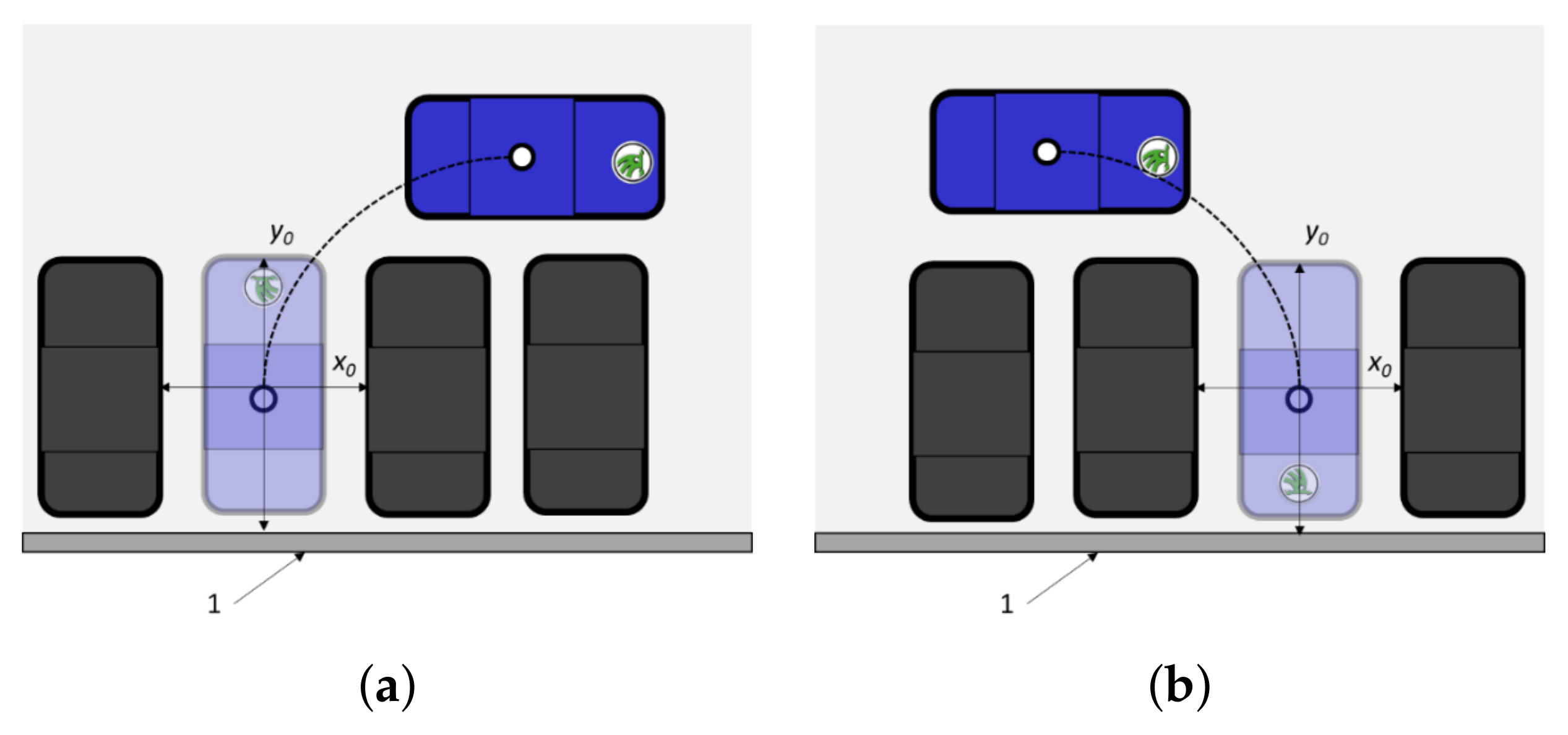
4.4. Perpendicular Parking Manoeuvre
The minimum requirement is that the perpendicular parking manoeuvre be performed with a parking slot between two vehicles of a similar size to the APS vehicle (
Figure 10). It is recommended that the bordering vehicles be aligned in the same direction as the APS vehicle in its target position and parallel to each other. The parking slot depth,
, is defined as the width of the APS vehicle plus
, and the slot length,
, is defined as the length of the APS vehicle. For the tested vehicle of a length between 4 m and 6 m,
= 1.2 m.
For the test parking scenario, two situations are considered, either with or without a reference curb. In the case with a reference curb, the vehicles are parked at a fixed distance perpendicular to it. In a situation without a curb, the longitudinal reference line is the virtual connecting line between the outer borders of the parked vehicles projected onto the ground. The test parking supports both reverse (
Figure 10a) and forward (
Figure 10b) driving manoeuvres.
4.5. Methodology
The overall APS is split into five major functional scenarios:
The APS starts from the drop-off zone;
Automated driving to a point of interest;
Automated manoeuvring into a parking slot;
Automated exiting of the parking slot;
Vehicle handover to the driver at the pick-up zone.
The driver can monitor the executed manoeuvres on a portable HMI device. The parking slot is confirmed by the driver before the autonomous parking manoeuvre.
The APS starts from the drop-off zone. The APS procedure starts with pulling up to the drop-off zone. The driver is responsible for driving to the drop-off zone. For simplicity, the AV and parking facility communicate at the drop-off zone (i.e., request—confirmation), which ideally ends with parking confirmation. The driver and passengers exit the vehicle. The vehicle checks whether all occupants have left the vehicle and all the doors are closed. When all the requirements are met, the APS vehicle assumes control of the vehicle. The parking slot is reserved.
Automated driving to a point of interest. The vehicle navigates to a point of interest. The point of interest is defined as the desired location, which is usually the assigned parking slot or the location after an emergency brake or full stop. Several manoeuvres are performed, following a straight or curved lane, turning left/right, etc. The end state is reached once the vehicle arrives at the desired point of interest without collisions. This scenario does not include manoeuvring into a parking slot.
Automated manoeuvring into a parking slot. The APS vehicle pulls up to the parking slot (i.e., point of interest); the parking manoeuvre can be executed. The desired free parking slot is identified and reserved following confirmation from the driver before step 1. The vehicle checks with perception sensors whether the parking slot is appropriate. The longitudinal or lateral actions are executed to correctly position the vehicle according to the type of parking slot (
Figure 9 or
Figure 10). The parking slots are arranged from 0° to 90° with respect to the lane. Reverse parking is recommended to reduce the required range of the rear-side sensors when leaving the parking slot in reverse. The end state is achieved provided:
The APS vehicle parks in the assigned parking slot without collisions;
The vehicle size does not exceed the parking slot;
The parking brake is activated, and the vehicle is in standby mode.
Automated exiting of the parking slot. The driver confirms the pick-up request and specifies the time and pick-up zone via the application. The APS vehicle is triggered to leave the parking space. The APS vehicle can manoeuvre out of the parking slot forwards and in reverse. However, exiting forwards is recommended. The manoeuvres “accelerate/decelerate”, “manoeuvre out of the parking slot”, and “reverse driving” are required. The execution is successful if no road user is harmed and the automated vehicle has left the parking slot. The APS vehicle autonomously drives to the pick-up zone to complete this step.
Vehicle handover to the driver at the pick-up zone. The APS vehicle stops at the pick-up zone and goes into standby mode. The driver enters the vehicle. The application frees up the parking slot. If the constraints are met and no road users have been harmed, the APS scenario is completed.
5. Results: Case Study
5.1. Environmental Set-Up
The APS offers a complete solution to parking by allowing quick-to-park drop-off/pick-up zones in most cities, modern multi-storey car parks, or public parking spaces marked by lines. This paper highlights the benefits of APS for everyday users and offers a summary of various preliminary tests that include communication among the AV, driver, and parking infrastructure. Both parallel and perpendicular parking manoeuvres are explored on the vehicle platform. The concept of reserving a parking space via an HMI was tested. All experiments were carried out with an electric vehicle prototype—a ŠKODA RAPID.
Preliminary tests were performed in Mladá Boleslav, Česana, Czech Republic—at a car park with the approximate dimensions of 110 m by 30 m. The structure of each test is such that the communication between the vehicle and the mobile device (automated on-street parking application) is established through an MQTT publish–subscribe network protocol and web pages. Once connected, the user can intuitively initiate sequences of commands that are then processed by the MQTT server and sent to the vehicle demonstrator.
The entire communication sequence is performed remotely via portable devices. The test vehicle is also equipped with communication technology. The test area is open to other road users (other vehicles, pedestrians, cyclists, etc.), making this a perfect environment to test an AV system under real-world conditions, as it must be able to interact with a dynamically changing environment.
Several different tests were performed, where, for instance, other road users were not present at the parking facility. In another study, the AV interacted with other road users. The system performed equally well in both instances.
5.2. Test Description
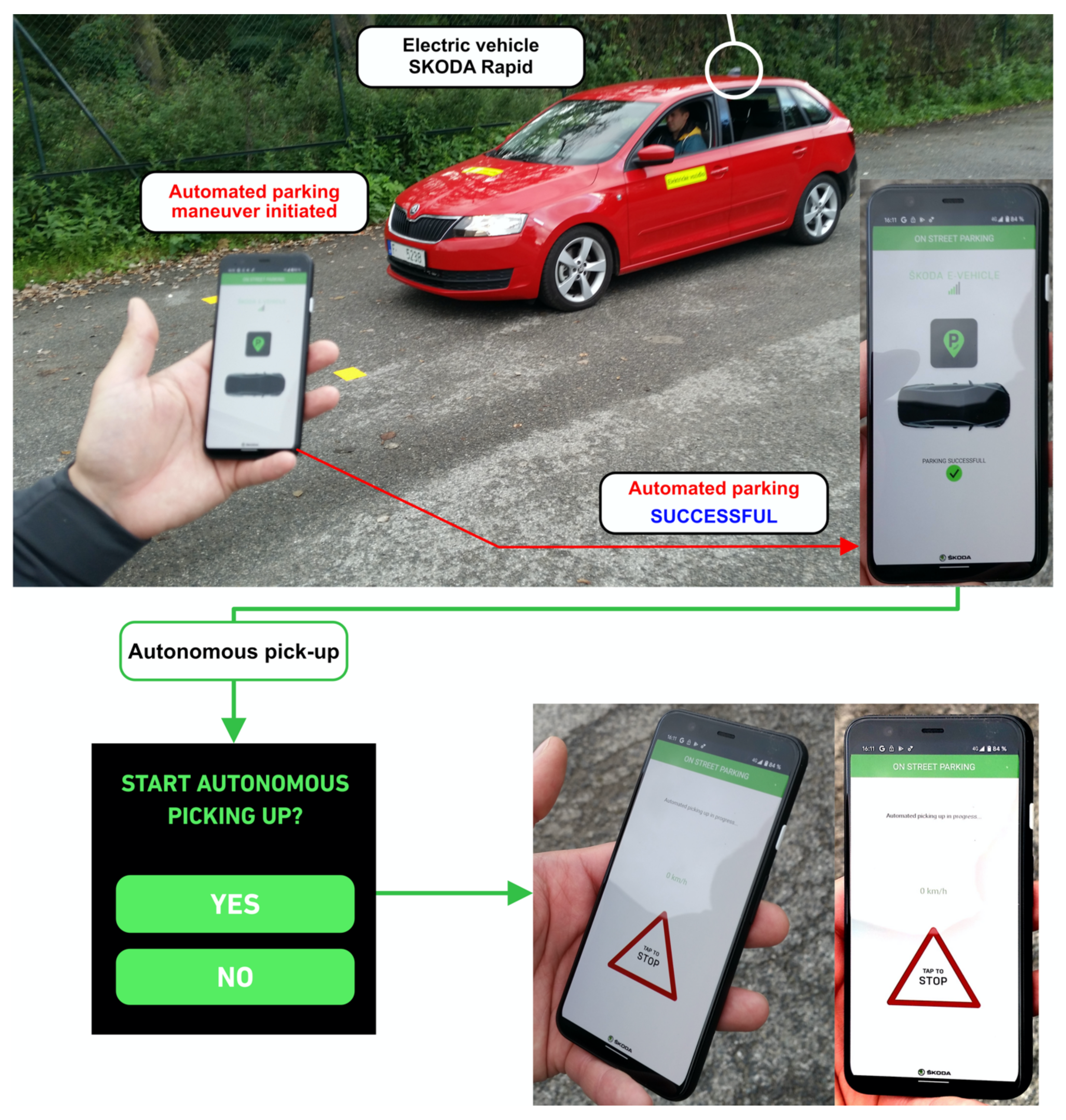
The illustration of real-life testing is introduced in
Figure 11. The AV has additional visual feedback on the people outside the vehicle cockpit. It has three modes providing information about the state of the vehicle. The blue light shows the AV’s operation in APS mode while stationary. A flashing blue light symbolises the direction the AV is moving in with the APS also active and no human driver being inside the AV. Finally, the green light flashes when the vehicle has successfully performed an autonomous manoeuvre, or the vehicle is ready for an automated parking manoeuvre. The green light also indicates when there is an ongoing search for parking facilities while the driver is still inside the vehicle. No light indicates manual vehicle control; the human driver is fully responsible for each manoeuvre.
The following functions of the mobile application were carried out during testing: reserving a parking space and the AV autonomously navigating to it, and recalling the AV from the drop-off and pick-up zones. These functions are described individually below.
5.2.1. Reserving a Parking Space and Autonomous Parking
In this phase, the communication between the driver and AV was tested during driving to validate the parking space reservation concept. The experiment was carried out as follows: The driver requested the autonomous parking function be performed. Based on the received information from the MQTT server, the vehicle displayed the notification “confirmation of reservation”. Once the driver had tapped “proceed”, the vehicle HMI system started navigating to the drop-off zone. After successfully performing the parking manoeuvre, the driver safely exited the vehicle.
The next test involved examining the communication between the mobile application and the MQTT protocol, such that the command “activate autonomous parking” was initiated by the driver and forwarded to the MQTT server. The vehicle parked without human assistance in the reserved parking space. This concluded the first validation phase (“Reserving a parking space and autonomous parking”), and triggered the second phase (“Recalling the AV from the pick-up zone”). At this preliminary stage of testing, the driver was present in the vehicle for safety reasons.
5.2.2. Recalling a Vehicle from the Drop-Off and Pick-Up Zone, Respectively
Firstly, the established communication between the mobile application and the MQTT server was verified by sending an activation message to the vehicle to drive from the drop-off zone to the pick-up zone in autonomous mode. Meanwhile, the vehicle was also receiving information about the geographical coordinates of the designated pick-up zone (it should be noted that the driver chooses the pick-up zone, and its location usually differs from the drop-off zone). The vehicle then autonomously drove to the designated pick-up zone at the coordinates provided. Several parameters, such as the vehicle’s trajectory and speed (including data on accelerating and decelerating, dynamic and safety aspects of driving, etc.), were recorded for testing and parameter analysis.
At the pick-up zone, the driver is informed by a green light near the antenna that the vehicle is ready for manual control to be assumed. The final testing phase involved a few additional actions to test other possibilities of the mobile application, namely, deactivating autonomous mode, unlocking the vehicle for the driver, and switching to manual drive mode. An example of using the mobile phone application is given in
Figure 11. The entire parking sequence relies on AV–smartphone communication and the capability of the integrated APS. In the event of functionality failure and the loss of connectivity, the AV immediately terminates the manoeuvre and applies the brakes.
6. Discussion and Conclusions
This paper presented APS development elements, which include (i) communication technology, (ii) HMI concepts, and (iii) validation methodology. The communication system is based on the MQTT protocol, where the AV, parking infrastructure, and driver communicate in a client–server manner. Decoding a transmitted signal was given as an example. The flow of information was briefly introduced. HMI technology includes multiple concepts for the most valuable communication purposes—the vehicle cockpit and main infotainment display, portable mobile devices, and webpages. The concepts were illustrated, and the interaction was explained. Moreover, additional comments for possible settings were mentioned. The results of the autonomous parking functionality in a conceptual parking environment were presented. Communication among system participants was highlighted in a selected infrastructure. The testing consisted of two phases—parking space reservation and autonomous parking, and recall of the AV from the drop-off/pick-up zones.
The results of the autonomous parking functionality in a conceptual parking environment were presented. Communication among system participants was highlighted in a selected infrastructure. The testing consisted of two phases—parking space reservation with autonomous parking, and recall of the AV from the drop-off/pick-up zones.
The methodology for APS verification according to functional safety and comfort requirements was described through an experimental case study. Both parallel and perpendicular parking manoeuvres are required for efficient system testing of safety and suitability at various parking facilities. The safety aspect of the system was prioritised in the methodology.
Several minor limitations of the proposed system must be highlighted: first, the communication and functionality were tested in a very simple scenario in a well-known environment. Second, basic perception technology was established between the vehicle platform and the surrounding environment. To enhance the performance of the manoeuvres, a more sophisticated array of sensors and an algorithmic update would be required. Furthermore, before the next stage of on-road testing, the APS must be validated in more intensive and dense traffic under complex environmental conditions.
In future work, the vehicle’s operating unit will be extended to integrate algorithms for increasing safety to allow partly autonomous charging [
37]. Data will be logged and synchronised directly from the vehicle to allow fast and straightforward processing between the mobile application and the MQTT server. Furthermore, integration with other autonomous driving functions is planned with the goal of full vehicle autonomy in urban mobility infrastructures.
Author Contributions
Conceptualisation, P.N., J.P. and A.A.; methodology, V.S.; software, Z.H.; validation, J.P., V.S. and Z.H.; writing—original draft preparation, J.P. and A.A.; writing—review and editing, A.A.; visualisation, J.P. and A.A.; supervision, P.N.; project administration, P.N.; funding acquisition, J.P. and P.N. All authors have read and agreed to the published version of the manuscript.
Funding
This research work, established under the FPA Grant agreement No. 2020/EIT/EIT KIC Urban mobility SL/090, is funded by the EIT, a body of the European Union.
Institutional Review Board Statement
Not applicable.
Informed Consent Statement
Not applicable.
Data Availability Statement
Not applicable.
Acknowledgments
The authors would like to express their sincere gratitude to KIC Urban Mobility. This work has been established under the FPA Grant agreement No. 2020/EIT/EIT KIC Urban mobility SL/090, supported by the EIT, a body of the European Union. The authors would like to express their great appreciation to the project coordinator of the Automotive Research Centre Niedersachsen (NFF), Technische Universität Braunschweig, R. Henze, S. Thal, A. Sonka, for their high professionalism and comprehensive guidance.
Conflicts of Interest
The authors declare no conflict of interest. The funders had no role in the design of the study; in the collection, analyses, or interpretation of data; in the writing of the manuscript, or in the decision to publish the results.
Abbreviations
The following abbreviations are used in this manuscript:
| APS | Autonomous Parking System |
| AV | Autonomous Vehicle |
| HMI | Human–Machine Interface |
| IoT | Internet of Things |
| MQTT | Message Queuing Telemetry Transport |
| QoS | Quality of Service |
References
- National Traffic Law Center. Investigation and Prosecution of Distracted Driving Cases; Report No. DOT HS 812 407; National Highway Traffic Safety Administration: Washington, DC, USA, 2017. [Google Scholar]
- Litman, T. Autonomous Vehicle Implementation Predictions; Victoria Transport Policy Institute Victoria: Victoria, BC, Canada, 2020; Available online: https://www.vtpi.org/avip.pdf (accessed on 28 November 2021).
- Creger, H.; Esprino, J.; Sanchez, A.S. Autonomous Vehicles Heaven or Hell? Creating a Transportation Revolution That Benefits All; The Greenlining Institute: Oakland, CA, USA, 2019; Available online: http://greenlining.org/ (accessed on 28 November 2020).
- Grayned, L. SAE International: Levels of Autonomous Driving and Sensor Packages; Oak Ridge Institute for Science and Education: Oak Ridge, TN, USA, 2020. [Google Scholar]
- Brennand, C.A.R.L.; Rocha Filho, G.P.; Maia, G.; Cunha, F.; Guidoni, D.L.; Villas, L.A. Towards a fog-enabled intelligent transportation system to reduce traffic jam. Sensors 2019, 18, 3916. [Google Scholar] [CrossRef] [PubMed] [Green Version]
- Hillar, G.C. MQTT Essential—A Lightweight IoT Protocol; Packt Publishing Ltd.: Birmingham, UK, 2017. [Google Scholar]
- Czekaj, J.L. Semi-Autonomous Parking Control System for a Vehicle Providing Tactile Feedback to a Vehicle Operator. U.S. Patent 5 742 141A, 6 June 1996. [Google Scholar]
- Moshchuk, N.K.; Litkouhi, B.B.; Chen, S.-K. Directing Vehicle into Feasible Region for Autonomous and Semi-Autonomous Parking. U.S. Patent 8 862 321 B2, 15 August 2012. [Google Scholar]
- Shen, Z.; Weng, F.; Albrecht, B. System and Method for Using Gestures in Autonomous Parking. U.S. Patent 9 656 690 B2, 30 October 2012. [Google Scholar]
- Bonnet, C.; Hiller, A.; Kuenzel, G.; Moser, M.; Schiemenz, H. Method for Autonomous Parking of a Motor Vehicle, Driver Assistance Device for Performing the Method and Motor Vehicle with the Driver Assistance Device. U.S. Patent 201 500 883 60A1, 16 November 2016. [Google Scholar]
- Stefan, F.; Gussen, U.; Arndt, C.; Busch, R. Method for Operating a Driver Assistance System to Perform an Autonomous Parking Maneuver. U.S. Patent 107 105 77B2, 15 January 2015. [Google Scholar]
- Paromtchik, I.E.; Laugier, C. Autonomous parallel parking of a nonholonomic vehicle. In Proceedings of the Conference on Intelligent Vehicles, Tokyo, Japan, 19–20 September 1996. [Google Scholar] [CrossRef]
- Jiang, K.; Seneviratne, L.D. A sensor guided autonomous parking system for nonholonomic mobile robots. In Proceedings of the 1999 IEEE International Conference on Robotics and Automation (Cat. No.99CH36288C), Detroit, MI, USA, 10–15 May 1999. [Google Scholar] [CrossRef]
- Oentaryo, R.J.; Pasquier, M. Self-trained automated parking system. In Proceedings of the ICARCV 2004 8th Control, Automation, Robotics and Vision Conference, Kunming, China, 6–9 December 2004. [Google Scholar] [CrossRef]
- Shoeibi, N.; Shoeibi, N. Future of smart parking: Automated valet parking using deep Q-learning. In Proceedings of the Distributed Computing and Artificial Intelligence, 16th International Conference, Avila, Spain, 26–28 June 2019. [Google Scholar] [CrossRef]
- Nakrani, N.M.; Joshi, M.M. Integration of dimension-adaptive obstacle avoidance algorithm in fuzzy-based autonomous vehicle parking. Int. J. Circuits Syst. Signal Process. 2021, 15, 367–376. [Google Scholar] [CrossRef]
- Jang, C.; Kim, C.; Lee, S.; Kim, S.; Lee, S.; Sunwoo, M. Re-plannable automated parking system with a standalone around view monitor for narrow parking lots. IEEE Trans. Intel. Transp. Sys. 2019, 21, 777–790. [Google Scholar] [CrossRef]
- Wu, G.; Xu, X.; Gong, Y.Y.; De Koster, R.; Zou, B. Optimal design and planning for compact automated parking systems. Europ. J. Operat. Res. 2019, 273, 948–967. [Google Scholar] [CrossRef]
- Zhang, J.; Gao, Z.-Y.; Yu, Y.-G.; Wang, T. Travel time model for a tower-based automated parking system. Int. J. Prod. Res. 2020, 59, 5422–5437. [Google Scholar] [CrossRef]
- Pereira, R.; Boukerche, A.; da Silva, M.A.C.; Nakamura, L.H.V.; Freitas, H.; Rocha Filho, G.P.; Meneguette, R.I. FORESAM—FOG paradigm-based resource allocation mechanism for vehicular clouds. Sensors 2021, 21, 5028. [Google Scholar] [CrossRef] [PubMed]
- Chippalkatti, P.; Kadam, G.; Ichake, V. I-SPARK: IoT based smart parking system. In Proceedings of the 2018 International Conference on Advances in Communication and Computing Technology, Sangamner, India, 8–9 February 2018. [Google Scholar] [CrossRef]
- Mackey, A.; Spachos, P.; Plataniotis, K.N. Smart parking system based on Bluetooth low energy beacons with particle filtering. IEEE Syst. J. 2020, 14, 3371–3382. [Google Scholar] [CrossRef] [Green Version]
- Shahzad, A.; Choi, J.-Y.; Xiong, N.; Kim, Y.-G.; Lee, M. Centralized connectivity for multiwireless edge computing and cellular platform: A smart vehicle parking system. Wirel. Commun. Mob. Comput. 2018, 2018, 7243875. [Google Scholar] [CrossRef] [Green Version]
- Haas, R.E.; Möller, D.P.F. Automotive connectivity, cyber-attack scenarios and automotive cyber security. In Proceedings of the 2017 IEEE International Conference on Electro Information Technology (EIT), Lincoln, NE, USA, 14–17 May 2017. [Google Scholar] [CrossRef]
- Huang, C.; Lu, R.; Lin, X.; Shen, X. Secure automated valet parking: A privacy-preserving reservation scheme for autonomous vehicles. IEEE Tran. Veh. Technol. 2018, 67, 11169–11180. [Google Scholar] [CrossRef]
- Kneissl, M.; Madhusudhanan, A.K.; Molin, A.; Esen, H.; Hirche, S. A multi-vehicle control framework with application to automated valet parking. IEEE Trans. Intell. Transp. Syst. 2020, 22, 5697–5707. [Google Scholar] [CrossRef]
- Okoso, A.; Otaki, K.; Nishi, T. Multi-agent path finding with priority for cooperative automated valet parking. In Proceedings of the 2019 IEEE Intelligent Transportation Systems Conference (ITSC), Auckland, New Zealand, 27–30 October 2019. [Google Scholar] [CrossRef]
- Brinkley, J.; Posadas, B.; Sherman, I.; Daily, S.B.; Gilbert, J.E. An open road evaluation of a self-driving vehicle human-machine interface designed for visually impaired users. Int. J. Hum. Comput. Interact. 2019, 11, 1018–1032. [Google Scholar] [CrossRef]
- Burns, C.G.; Oliveira, L.; Thomas, P.; Iyer, S.; Birrell, S. Pedestrian decision-making responses to external human-machine interface designs for autonomous vehicles. In Proceedings of the 2019 IEEE Intelligent Vehicles Symposium (IV), Paris, France, 9–12 June 2019. [Google Scholar] [CrossRef] [Green Version]
- Manawadu, U.E.; Kamezaki, M.; Ishikawa, M.; Kawano, T.; Sugano, S. A multimodal human-machine interface enabling situation-adaptive control inputs for highly automated vehicles. In Proceedings of the 2017 IEEE Intelligent Vehicles Symposium (IV), Los Angeles, CA, USA, 11–14 June 2017. [Google Scholar] [CrossRef]
- Faas, S.M.; Baumann, M. Light-based external human-machine interface: Color evaluation for self-driving vehicle and pedestrian interaction. In Proceedings of the Human Factors and Ergonomics Society Annual Meeting, Seattle, WA, USA, 28 October–1 November 2019. [Google Scholar] [CrossRef]
- Jiménez, F.; Clavijo, M.; Cerrato, A. Perception, positioning and decision-making algorithms adaptation for an autonomous valet parking system based on infrastructure reference points using one single LiDAR. Sensors 2022, 22, 979. [Google Scholar] [CrossRef] [PubMed]
- Kenitar, S.B.; Salhaoui, M.; Arioua, M.; Younes, A.; González, A. Evaluation of the MQTT protocol latency over different gateways. In Proceedings of the 3rd International Conference on Smart City Applications (SCA 18), Tetouan, Morocco, 10–11 October 2018. [Google Scholar] [CrossRef]
- Eclipse Mosquitto™: An Open-Source MQTT Broker. Available online: https://mosquitto.org/ (accessed on 12 October 2021).
- Mishra, B.; Mishra, B. Evaluating and analyzing MQTT brokers with stress-testing. In Proceedings of the 12th Conference of PHD Students in Computer Science, Szeged, Hungary, 24–26 June 2020. [Google Scholar]
- Institute of Information Theory and Automation. MQTT Server. Available online: http://ucs.utia.cas.cz/MQTT_wall/ (accessed on 12 October 2021).
- Schwesinger, U.; Bürki, M.; Timpner, J.; Rottmann, S.; Wolf, L.; Paz, L.M.; Grimmett, H.; Posner, I.; Newman, P.; Häne, C.; et al. Automated valet parking and charging for e-mobility. In Proceedings of the 2016 IEEE Intelligent Vehicles Symposium (IV), Gothenburg, Sweden, 19–22 June 2016. [Google Scholar] [CrossRef]
| Publisher’s Note: MDPI stays neutral with regard to jurisdictional claims in published maps and institutional affiliations. |
© 2022 by the authors. Licensee MDPI, Basel, Switzerland. This article is an open access article distributed under the terms and conditions of the Creative Commons Attribution (CC BY) license (https://creativecommons.org/licenses/by/4.0/).


