Article

A Cloud-Based Data Storage and Visualization Tool for Smart City IoT: Flood Warning as an Example Application

1
Department of Electrical and Computer Engineering, University of Virginia, Charlottesville, VA 22904, USA
2
Department of Computer Science, University of Virginia, Charlottesville, VA 22904, USA
3
Department of Civil and Environmental Engineering, University of Virginia, Charlottesville, VA 22904, USA
4
Department of Systems and Information Engineering, University of Virginia, Charlottesville, VA 22904, USA
*
Author to whom correspondence should be addressed.
Smart Cities 2023, 6(3), 1416-1434; https://doi.org/10.3390/smartcities6030068
Submission received: 15 April 2023 / Revised: 13 May 2023 / Accepted: 16 May 2023 / Published: 19 May 2023
(This article belongs to the Topic IoT for Energy Management Systems and Smart Cities)

Abstract

:
Collecting, storing, and providing access to Internet of Things (IoT) data are fundamental tasks to many smart city projects. However, developing and integrating IoT systems is still a significant barrier to entry. In this work, we share insights on the development of cloud data storage and visualization tools for IoT smart city applications using flood warning as an example application. The developed system incorporates scalable, autonomous, and inexpensive features that allow users to monitor real-time environmental conditions, and to create threshold-based alert notifications. Built in Amazon Web Services (AWS), the system leverages serverless technology for sensor data backup, a relational database for data management, and a graphical user interface (GUI) for data visualizations and alerts. A RESTful API allows for easy integration with web-based development environments, such as Jupyter notebooks, for advanced data analysis. The system can ingest data from LoRaWAN sensors deployed using The Things Network (TTN). A cost analysis can support users’ planning and decision-making when deploying the system for different use cases. A proof-of-concept demonstration of the system was built with river and weather sensors deployed in a flood prone suburban watershed in the city of Charlottesville, Virginia.

1. Introduction

Recent advances in information and communication technologies (ICT) are enabling Internet of Things (IoT) smart city projects to collect and analyze vast amounts of data in an effort to support more environmentally and economically sustainable communities [1,2]. For instance, smart stormwater projects have shown successful IoT-based infrastructure-monitoring applications to address communities’ operation and planning challenges [3,4,5]. As IoT devices become more pervasive, the collected data is expected to play an increasingly central role to inform communities’ decisions and, therefore, it is critical to develop and maintain cyber infrastructure to collect, store, and visualize sensor data.
However, as a growing number of new ICT technologies become available, the task of developing and integrating hardware and software solutions for IoT smart city projects can demand extensive specialized knowledge in different ICT domains [6,7], which can be challenging for IoT system designers. To reduce IoT systems’ design effort and to make IoT solutions more accessible, The Things Industry (TTI) [8] created and sponsored The Things Network (TTN) [9], a set of open-source tools to provide the basic software infrastructure to deploy IoT sensors based on LoRaWAN [10,11], a low-power and wide-area network (LPWAN) wireless communication protocol. This open-source project enables contributors around the globe to publicly share TTN compatible gateways that can connect LoRaWAN sensors to a network server known as The Things Stack, which is maintained by TTI. The use of TTN for smart city projects has been successfully demonstrated in the literature for different applications (e.g., [3,12]), while it also benefits communities by creating an open LoRaWAN communication infrastructure that can be leveraged by other IoT projects such as air quality monitoring [13].
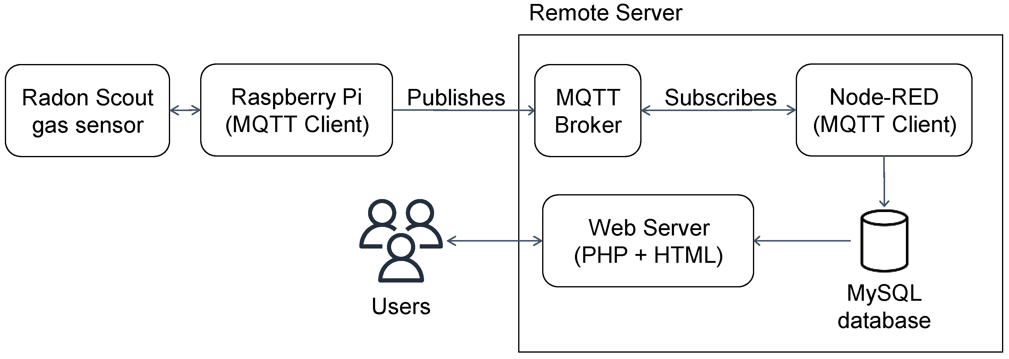
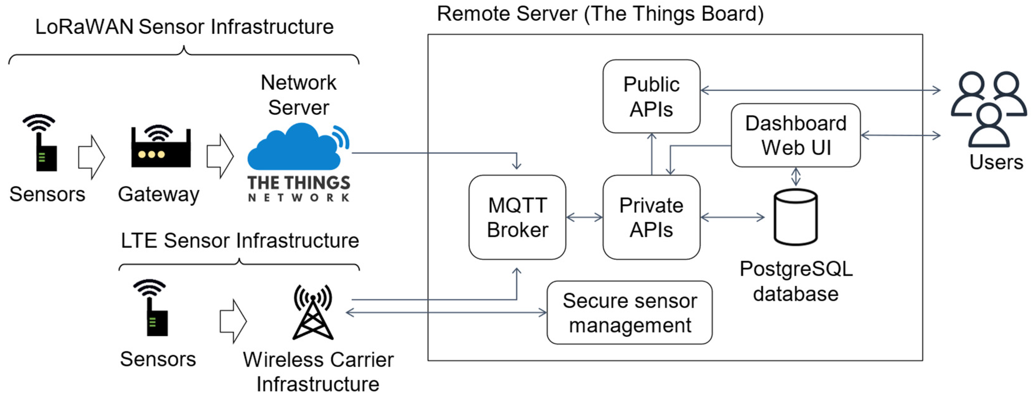
Although deploying an IoT system is greatly simplified by using TTN tools, their goal is to provide only the network server infrastructure and leave the application server to be developed by users. For instance, long-term data storage, graphical user interfaces (e.g., plotting tools), and the capacity to send alarm notifications are functionalities not supported by TTN’s network server. To achieve such functionalities, users need to develop their own application server or adopt third-party service providers such as Ubidots [14] and myDevices [15]. Another possible solution is to develop a custom server using a TTN open-source networking solution and modify it to include application layer functionalities; however, this solution implies an increased server workload and code maintenance requirements when compared to only developing and hosting application layer functions.
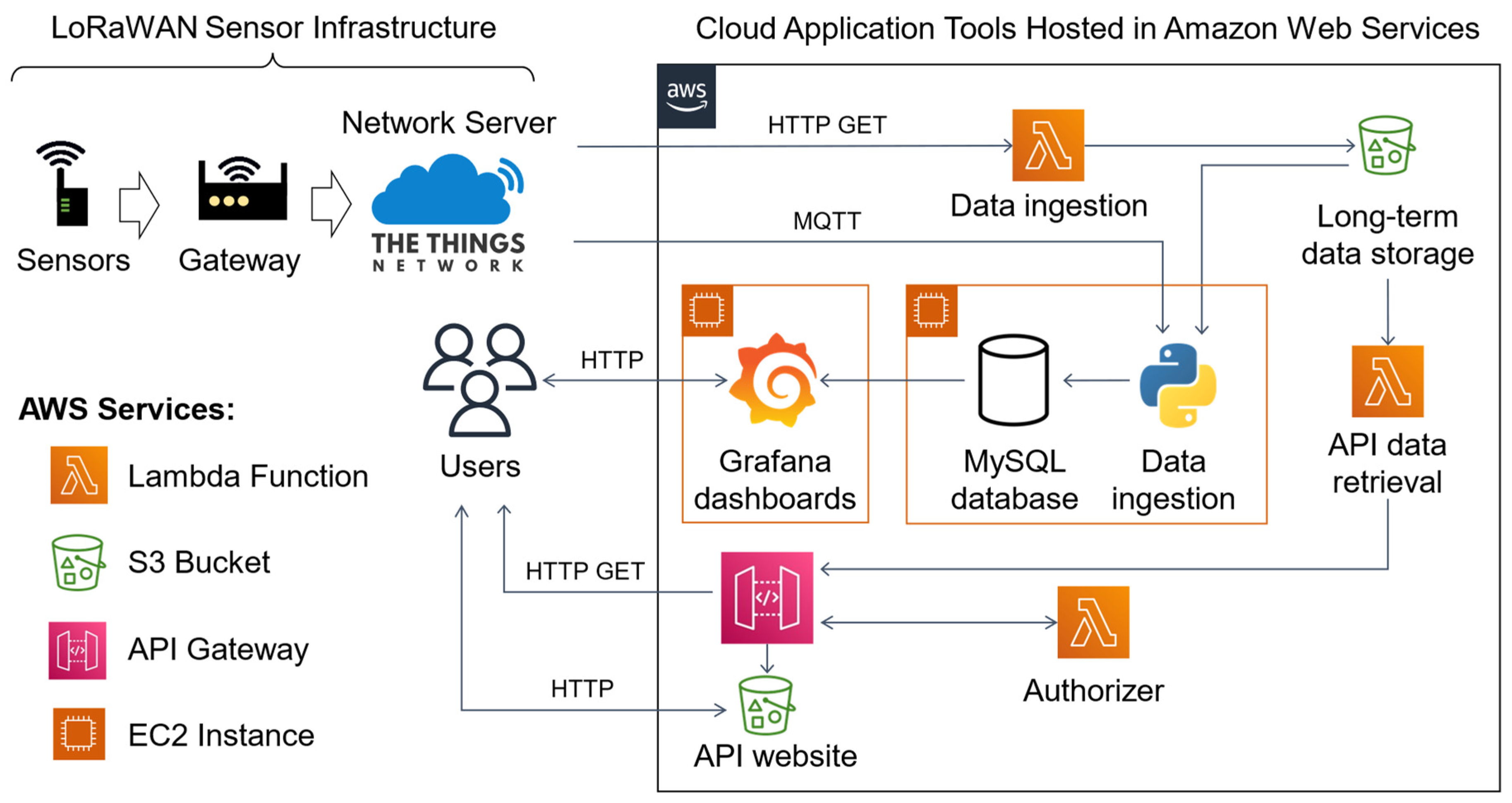
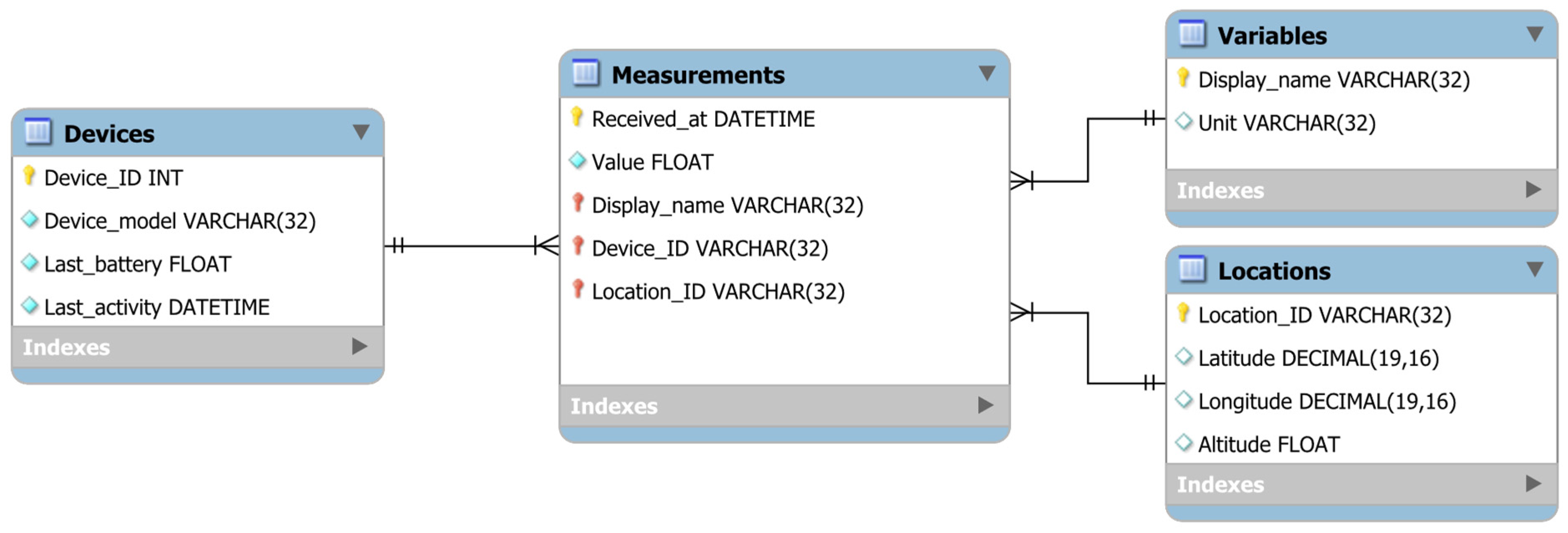
While third-party application servers might provide great value to many applications, users might still decide to develop their own application server solution to achieve more control over their data, to create customized application solutions, or to reduce recurring costs. However, developing an application server implies selecting, developing, and integrating software modules to achieve the application’s goals, which can be challenging due to the large diversity of architecture options and software solutions currently available as commercial products and open-source modules. In this context, IoT application case studies can offer users a valuable insight into developing and integrating software systems to meet application goals. To help guide users on the path of creating integrated IoT smart city applications, we introduce our use case of a flood warning system for a suburban watershed in Virginia, USA. Our system uses a pressure sensor and two ultrasonic sensors to monitor water levels at three locations on the stream network, and a weather station to monitor precipitation rates. All our monitoring devices use LoRAWAN to communicate to TTN’s network server. We developed and integrated a scalable set of cloud-based application tools to perform long-term data storage, data visualization, and automated alarm notification functionality. We discuss the implementation challenges and insights for our system, as well as a cost analysis using Amazon Web Services (AWS). To support users’ planning and decision-making, we included a cost analysis section where we evaluate how costs currently evolve with time, number of sensors, and data storage requirements.
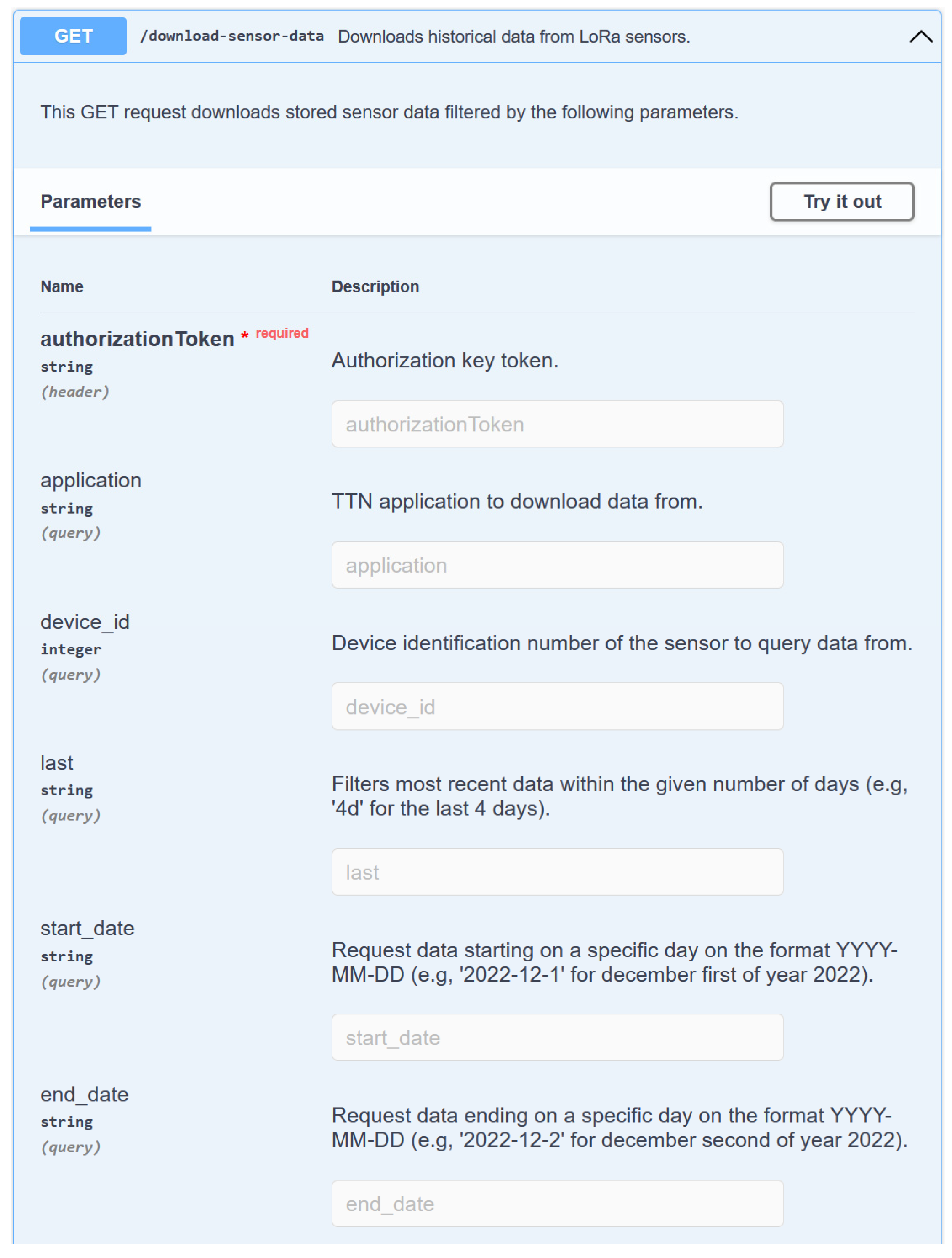
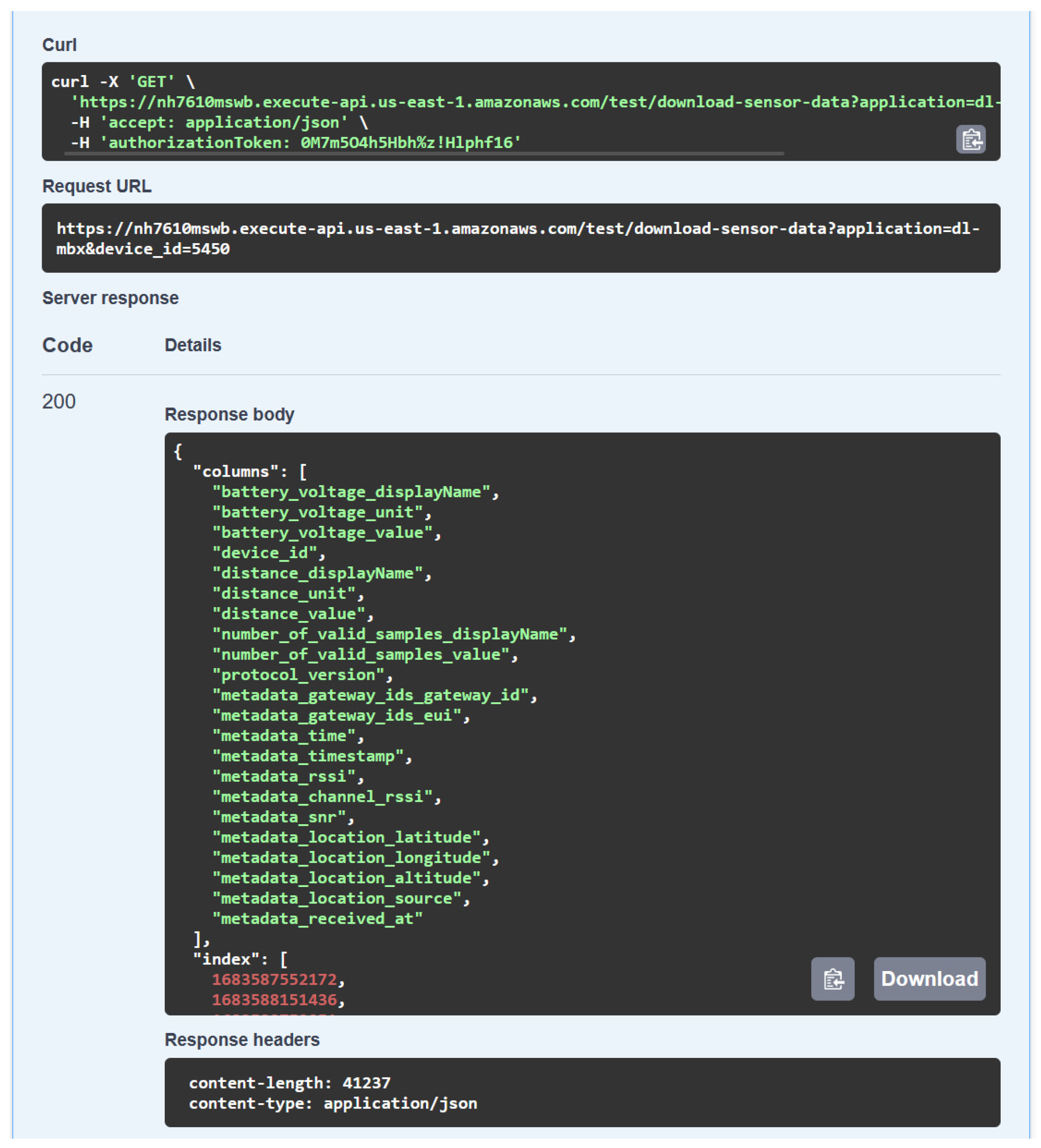
This paper’s main contributions can be summarized as: (1) our work provides practical insights on the development of cloud-based tools for IoT applications, an emerging area that is frequently overlooked in empirical IoT research; (2) we propose a general cloud backend system architecture that can guide IoT developers to quickly prototype smart city applications by using our demonstrated tools such as serverless data ingestion for IoT historical backup data storage, on-demand MySQL database and Grafana servers, and a RESTful API for programmatical data access; and (3) we perform a cost analysis for the first few years of using AWS cloud services in an IoT application, highlighting the cost-effectiveness of our proposed solution, and providing to IoT developers a cost estimate of these cloud services under a varying number of sensors and data rate.
This work is organized as follows: in Section 2, we present an overview of related works on IoT for smart city projects that share similarities with our solution; in Section 3, we introduce our example application along with its objective and goals; in Section 4, we present the use case, the adopted overall system architecture, and the design requirements; in Section 5, we present our main results and discussion; finally, in Section 6, we present our final conclusions.

2. Related Work

To illustrate some of the possible IoT architecture solutions to smart city projects, we selected two works, the first one targeting Radon gas concentration monitoring [16] and the second one a smart stormwater system using LoRaWAN and TTN [3]. The Radon gas concentration monitoring work was selected to represent a typical IoT project, where the study made use of available components and tools to build its own remote sensing solution. The smart stormwater system work was selected as an example of a similar application goal using LoRaWAN and TTN, but one adopting alternative design components to our system.

2.1. Radon Gas Monitoring Application

To monitor the concentrations of Radon gas in indoor locations, the authors of [16] presented an IoT system that collects and transmits data to a remote server where values are stored. We summarize the IoT system architecture used for the Radon gas application in Figure 1.
As sensing devices, the authors adopted a commercially available Radon Scout gas sensor connected to a Raspberry Pi 3 device, used as a controller, and connected to the internet. The Raspberry Pi was programmed to read and transmit sensor data to their remote server through a message queuing telemetry transport protocol (MQTT) [17] communication interface. The server receives sensor data through a MQTT broker that publishes received messages to a subscribed MQTT client managed by a Node-RED [18] application responsible for parsing and storing the data in a MySQL database [19]. Finally, a web server interface was created to read the database and display a table of stored sensor readings to users.
For our flood warning use case, we adopted a commercially available LoRaWAN gateway and sensors. While our LoRaWAN gateway required internet connectivity similarly to the Raspberry Pi controller used in this related work [16], the LoRaWAN sensors can be deployed hundreds of meters away from the gateway, which allowed us to reach our desired deployment locations. We used TTN as our network server to register and manage devices, reducing development time and enabling better scalability as new sensors only need to be registered to our TTN application. For this related work [16], authors needed to individually configure the MQTT clients in each one of their Raspberry Pi devices to publish sensor measurements to their server’s MQTT broker, as well as individually manage any security key. Instead of using Node-RED to parse and ingest data as adopted in this related work [16], we used a python script to manage the data ingestion and parsing system that periodically receives data from our TTN application through a MQTT client. As our data storage solution, we also adopted a MySQL database, as similarly presented in [16], but we also decided to create a dedicated long-term cloud-based storage solution using AWS S3 [20] as a backup to the MySQL database. For this long-term data storage backup, we used AWS Lambda [21] service to create a serverless and independent data ingestion solution to periodically request data from TTN storage integration and store it in AWS S3. Instead of displaying sensor data through a website server, we created a dashboard on a Grafana application [22] to plot relevant sensor information such as measurements and battery voltage level.
Although the authors of this related work were targeting an indoor Radon gas monitoring application, some of their system components could be adopted by other IoT applications such as in collecting and displaying data from LoRaWAN sensors connected to TTN. For instance, TTN offers a MQTT Broker service that can publish received LoRaWAN messages to subscribed clients, making it possible to re-use the server infrastructure described in [16] by updating the broker address, client credentials, parsing function, database configuration, and sensor measurement variables.

2.2. Smart Stormwater System Application

For the stormwater monitoring system introduced in [3], the authors deployed a set of sensors around the Illawarra-Shoalhaven region in Australia. Their sensors relied on either the LoRaWAN or 4G cellular network to communicate, depending on each sensor’s required data rate. Sensing devices included water-level sensors, tipping bucket rain gauges sensors, pressure and humidity sensors, lagoon monitoring devices, and a culvert blockage monitoring system. To receive data collected by the LoRaWAN based sensors, the authors deployed a network of TTN gateways in the study region. This gateway infrastructure was also seen by the authors as an investment to support other future applications including education-related projects. We summarize the IoT system architecture used for the smart stormwater system application in Figure 2.
To store and display the collected data, authors of [3] adopted the open-source solution provided by the ThingsBoard [23], using the MQTT protocol to receive LoRaWAN sensor data from TTN and store it in a PostgreSQL database. ThingsBoard also provides alerting and graphical interface tools to generate custom dashboards to display sensor data in real time and send automated alert messages. The authors did not specify whether the server solution was hosted in a computer owned by them or a cloud solution, however, ThingsBoard offers a platform as a service solution where they host their system in the cloud with pricing currently ranging from USD 10/month (Maker) to USD 749/month (Business).
Despite offering data storage, API access, and visualization tools, Thingsboard is a turnkey software solution that requires users to have an always-running server to ingest, store, and visualize data. On the other hand, our solution leverages cloud services to break down data ingestion from other on-demand uses, namely: (1) a serverless data ingestion and storage cloud application using AWS Lambda [21] and AWS S3 [20]; (2) a virtual machine instance with a MySQL database to provide responsive data access; and (3) a second virtual machine hosting a Grafana server [22] to provide data visualization. Our serverless data ingestion solution requires only a few lines of code to query sensor data from TTN, parse, and store data as a csv file in AWS S3, thus reducing the complexity to manage bugs and update the system when compared to full servers such as ThingsBoard [23]. Using dedicated virtual machines for a database and visualization allows for tailored resource allocation based on the application needs, the flexibility to provide only the needed service, and code isolation to facilitate upgrading, adding, or switching services (e.g., replacing MySQL with PostgreSQL).

3. Example Application Motivation and Objectives

With the increase in weather variability and flooding [24], it is vital that communities launch flood mitigation initiatives for the safety and quality of life of their residents. To create a sensing and alert system, we need to collect real-time sensor data from various locations around a city, and parse, store, provide responsive visualization, and transmit alert messages. For preemptive flood management strategies, we also need to collect data about existing infrastructure and land features to model stormwater flow and forecast future flood conditions.
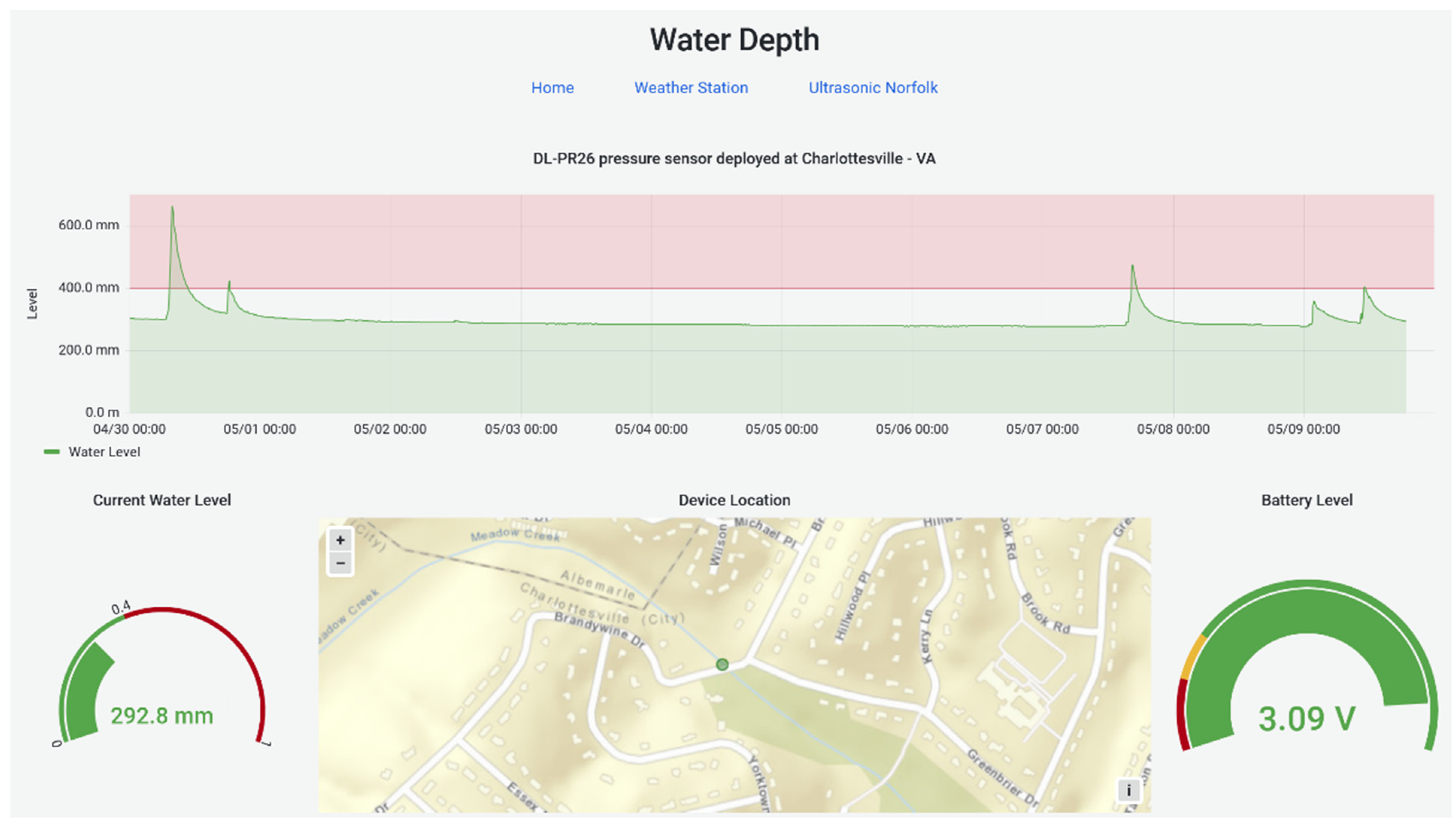
This example application’s main goal was to demonstrate cloud-based application solutions to support the monitoring and alerting of flooding events. The basic features of our application system include data collection, storage, visualization, and alert creation as well as a RESTful API to provide data access to data-driven environmental forecasting and physics-based stormwater flow simulation. Although this use case is focused on flood warning, we describe each component and lessons learned in a general way, so it can be easily translated to other smart city use cases.

4. Methodology

4.1. System Architecture Overview

Data flows from sensors to our cloud-based software solution as depicted in the system architecture diagram in Figure 3. We built our cloud-based system using Amazon Web Services (AWS) to take advantage of their latest resources and capabilities such as serverless functions (AWS Lambda [21]), data storage (Amazon S3 [20]), API gateway interfaces (Amazon API Gateway [25]), and computing instances (Amazon EC2 [26]).
Using AWS Lambda [21], sensor measurements are queried from our TTN application, transformed, and uploaded as csv files to our long-term cloud data storage solution in an AWS S3 bucket [20]. We adopted a MySQL database server to provide responsive data access to our application. The MySQL database is hosted in an AWS EC2 instance [26] alongside a python script that ingests historical sensor data when the virtual machine starts up, and another script that connects to our application’s TTN MQTT broker to receive and ingest real time sensor data. The data is then queried for visualization, monitoring, and alerts through a graphical user interface (GUI) tool, Grafana [22]. Both MySQL and Grafana EC2 instances are only started under demand if users need fast access to structured data or a monitoring dashboard, respectively. Sensor data can also be programmatically downloaded using our RESTful API, as, for instance, in scripts to perform data analysis tasks in Jupyter notebooks [27], or to perform modeling tasks with Storm Water Management Model (SWMM) software [28]. We also hosted a static website to document the API interface and offer users direct access to data download using Swagger UI [29]. While not explicitly shown, we assume simulation and modeling tasks will be performed by users in their own servers that could either be hosted by EC2 instances in AWS, by other cloud providers, or also hosted on their own computer machines.

4.2. Design Requirements

Our cloud-based system requires several different components to work in conjunction to meet application requirements. Firstly, the deployed IoT sensors must successfully relay messages to the TTN network server to deliver real time data. The data must then be received, processed, and stored in our MySQL database and the S3 long-term data storage for backup purposes. To make the system simpler to develop and manage, we adopted a single cloud service provider to develop our application’s services and tools. In this system’s case, it was hosted by provisioning services through Amazon Web Services (AWS). Next, for this system to be sustainable and meet different users’ cost constraints, it must operate at minimum cost and have efficient resource consumption. The system must also be intuitive and straightforward to deploy, use, maintain, and modify.

4.3. System Components

4.3.1. Sensors, TTN, and Ingestion to Cloud Platform

As proof-of-concept, we deployed three water level monitoring sensors and one weather station in a flood prone watershed in Charlottesville, VA. All four devices were connected to The Things Network (TTN) through a LoRaWAN gateway installed in the same neighborhood region as the devices. We utilized commercial sensors from Decentlab [30] to focus efforts on data gathering, storage, and analysis systems rather than on the sensor’s hardware and software. Another motivation behind this decision was to make our solution more general and easily translatable to other smart city projects based on sensor hardware compatible with The Things Network (TTN). We have left sensor deployment details out of the scope of this work, since our main goal is to advance the software backend infrastructure of IoT systems.
The sensors communicated using LoRaWAN [10,11] with TTN-compatible gateways that interfaced with TTN network server through an internet connection. The sensors were connected to TTN to enable cost effective interfacing and management, and to utilize the platform’s available single-day storage via TTN’s data storage integration service. To query data from TTN and upload it to the Amazon Web Service (AWS) stack, we wrote a python function to perform a HTTP GET request to retrieve data for a particular application. This data querying python function runs as an Amazon Lambda service that is periodically executed, set initially to run in one-hour intervals. To ingest real-time data to our MySQL database, we used MQTT clients connected to our TTN applications’ MQTT brokers. TTN network server MQTT broker publishes new sensor data to our MQTT clients as soon as it is available in their server, providing our application with timely access to information.

4.3.2. Cloud Platform and Used Services

We decided to develop our application using AWS tools, but the same application architecture can be reproduced using equivalent services from other cloud providers. For regions impacted by flooding, high availability of the computing backend is imperative due to the need for quick analysis of the incoming weather and real time water level data. AWS offers high availability, which includes regional failovers in case a data center is taken offline. Deploying and redeploying resources on AWS can also be quickly automated using AWS CloudFormation [31], a tool used to provision specified resources (such as Lambda, EC2, RDS, etc.) through a provided script. The code written for the backend of the cloud-based system can be found at [32].

Amazon Lambda

AWS provides a serverless computing platform known as Amazon Lambda [21], which allows users to run their custom functions on demand. The underlying infrastructure of Lambda is maintained by AWS, which means the system developer must only worry about choosing the correct runtime environment to deploy their code. Using Lambda, the sensors are queried for uplink data at specified intervals. The uplink is then parsed, and the data is transformed to only include information pertinent to the application. The sensors’ uplink data is uploaded to S3 for long-term storage and becomes available to be queried into the MySQL database when needed. After the Lambda function finishes uploading the transformed data, it automatically shuts off, allowing the user to pay only for the computing time and memory resources used rather than provisioning a continuously running machine (e.g., EC2). Lambda was chosen for our solution due to ease of scalability with future added devices, monitoring, high availability, and resource efficiency. For instance, if a new TTN application is added to the system, the existing Lambda function can be promptly updated to query sensor data. Should multiple applications need to report data in overlapping intervals, the same Lambda function can run in parallel of up to 1000 instances if needed.
The Lambda functions for this use case require modification from the default settings. We used the AWS SDK Pandas Lambda Layer [33] to query from TTN, parse data, and to store or read data from a S3 bucket. Python’s Pandas module is used to quickly transform and manipulate data. The urllib3 module is used to send HTTP requests to The Things Network’s storage integration and to retrieve sensor data. Other configurations for the Lambda function include setting the allocated memory to 192 MB (determined by AWS Compute Optimizer [34]), a timeout limit of 1 min, and being triggered to run once every hour. The lambda function triggering period can be adjusted based on application needs, where shorter periods translate to lower latency between data being available on TTN and stored in the S3 bucket but also resulting in higher costs for the lambda function computing service.
Another use we make of AWS Lambda is to return stored sensor data requested by our RESTful API and to manage user authentication. When receiving a query from Amazon Gateway API, a lambda function is initially executed to check an authorization token provided in the API request and authorize or deny the API request. If authorization is granted, a second lambda function reads, and parse data stored in the long-term data storage solution in the S3 bucket to return the required data to the API gateway. This lambda function to query data from S3 and return to the API gateway is configured to allocate 512 MB of data as a compromise between cost and performance to serve the API functionality and timeout limit of 1 min. The authorizer function uses the default settings of 128 MB memory allocation and 3 s timeout due to the simplicity of our currently adopted solution that only checks if the authorization key input matches a hardcoded string value.

Amazon S3 Data Storage

Amazon Simple Storage Solution (S3) is a cost-effective way to store data for extended periods. Data collected by sensors are uploaded in S3 for long-term storage as a read-only resource of the raw data feed. These readings can be used to repopulate the database in case of a database failure or migration and can be performed using the python library created for this system. AWS also maintains a python module (BOTO3 [35]) that allows users to download a copy of the readings from S3 to a local machine. All readings in S3 are currently stored as the AWS Standard tier for regular access for this application example.
Another use for the S3 storage is hosting static websites. We used a S3 bucket to store our RESTful API documentation using the Swagger UI interface [29]. Our website is based on the Swagger UI demonstration provided in their github page, and adapted to read an OpenAPI 3.0 description of our API service. The static website contains the API server address, a description of the required header, all accepted parameters, and the possibility to perform an API GET request trial with parameters provided by the user.

Amazon Elastic Cloud Compute

To host MySQL and Grafana, two Amazon Elastic Compute Cloud (Amazon EC2) instances were provisioned. Amazon EC2 allows for a continuous computing platform on the cloud, which allows access to the database and Grafana when needed. The developed system uses t3.micro instances with 10 GB storage, which fits the needs of this example application by minimizing costs while still maintaining a reliable performance for the relatively low number of sensors currently in the system. A more capable instance could be used to serve a larger number of users or for a use case requiring quicker response times. For this study, MySQL and Grafana were hosted on two separate EC2 instances for simpler management and increased flexibility, allowing, for example, the easy replacement of visualization software or on-demand use of MySQL database to allow fast data access to applications. It may also be worthwhile to adopt an AWS Relational Database Service (RDS) [36] instead of an EC2 instance running MySQL as the system database solution and then scale the RDS database based on the application’s requirements for maintainability and access speed. This was considered, but not implemented in this study because RDS comes at a higher cost. However, RDS has the advantage that it provides built-in scalability as data volumes and users grows. The Section 5 includes a cost comparison between these alternatives for hosting the database and a discussion of pros and cons of each alternative.

4.3.3. Relational Database Design and Implementation

As our relational database, we selected MySQL as a simple solution with wide community support. We deployed MySQL on the cloud through Bitnami [37], which provides a pre-configured virtual machine image which is ready to be loaded to an Amazon EC2 instance. We created an entity relationship diagram (ERD) to normalize the sensor readings as shown in Figure 4. The ERD is centered around the Measurements entity, which stores the value of individual data points along with the time of data collection (Received_at). The Devices entity stores the device’s unique identifier (Device_ID), the device’s model (Device_model), the last received battery reading of the device (Last_battery), and the last activity timestamp (Last_activity). Similarly, the Locations entity contains data on the latitude, longitude, and altitude for each location that data is collected from, along with a unique identifier for each location. For each value in the values table, the Variables entity stores the data points’ unique display name and the unit of the variable. The Measurements entity has a one-to-many relationship with the three other entities, meaning that each value data point can only have one device, variable, and location, while the remaining entities can have many values for each data point in their tables. This ERD was developed by advancing an approach from previous related research [38]. This design of the database allows for easy further advancement and change as additional devices and variables can be more easily incorporated.

4.3.4. Graphical User Interface

This system allows users to visualize and monitor data through Grafana, an open-source analytics platform for querying, visualizing, and alerting on data metrics. Grafana was selected as the software solution to visualize incoming data due to its dynamic dashboards, built-in alerting capabilities, and its specialization in time series data.
Grafana was deployed on the cloud through Bitnami [37], which provides a system image of a pre-configured Grafana stack on AWS. A connection was then made to the MySQL database in Grafana to access the data for visualization. Dashboards of each monitoring station were created to display relevant information for users. In Figure 5 we show an example of the dashboard for the water depth monitoring station. This dashboard includes a graph of the water depth over time, statistics on the water depth values for the set time range, a water level gauge of the current depth, a map of the sensor station location, and a gauge of the sensor battery level. The water depth graph and gauge allow users to view the current and past water levels in relation to a threshold of 0.4 m to signify flooding. Grafana’s built-in alert system can send alert notifications if the incoming data triggers a set alert rule. As an example, the water depth dashboard has alert rules set to send a notification through the messaging application Slack [39] if the 0.4 m threshold is met, although sending alerts to other systems or via email is also possible.

4.3.5. RESTful API

Our RESTful API serves as a programmatic interface for users to quickly download data from sensors. We created the API using the Amazon API Gateway service [25] and lambda functions, both to manage API access and to read, parse, and return data from our long-term data storage solution in AWS S3. To document our RESTful API and provide easy access to sensor data, we created a static website using Swagger UI and it is currently hosted using AWS S3 buckets. We also enabled CORS in our API Gateway service, and we added a custom header with an authorization token for access control.
We described our API following the Open API 3.0 framework and stored it as a json file loaded to a specification variable in the javascript code for our documentation website. To download data using the API, the user will be required to input a valid authorization token to be granted access. Although we are currently using a simple custom lambda function to grant access, other more comprehensive user access management tools can be used in future versions, such as Amazon Cognito [40]. Other available parameters to customize the sensor data request are: “application”, which selects which TTN application to download data from; “device_id” which selects devices using a unique identifier; and “last” or “start_date” and “end_date” which allow the selection of periods of time to download data. Using the “last” parameter, users can retrieve data collected by the sensors from the time of querying to the day specified. Using the “start_date” parameter, users can specify the beginning of the time range of the dataset to download. By default, if only one of “start_date” or “end_date” parameters are provided, data from the single specified day will be returned. Using the API, the user can request datasets for any of the available sensors. In Figure 6, we illustrate a typical use of the API to request data from a pressure sensor by using the Swagger graphical user interface. In Figure 7, we show a typical API call with parameters and the response.

5. Results and Discussion

5.1. Discussion of Alternative System Components and Potential System Enhancements

5.1.1. Cost Analysis of Cloud Services

The first two versions of the databases created for this application example were hosted in a MySQL database using Amazon Aurora [41] and then Amazon RDS [36]. For the application example needs, Aurora and RDS costs presented a constraint, which is the reason we chose two EC2 instances to host MySQL and Grafana that meet user requirements at a lower average cost. The current virtual machine cyber infrastructure costs between USD 24 and USD 210/year, depending on how long the EC2 instances will be required to be available. However, the database hosted this way may require maintenance such as updating software, or services to fix bugs, along with providing no regional failover. In the event that an AWS region experiences an outage, regional failover allows a copy of the database hosted in a separate region to quickly take over operations. Since in our use case we might not need Grafana and the MySQL database to be always available, the EC2 instances can be shut down and only started under demand, for example when users expect an incoming storm. Turning off the EC2 instances reduces the recurring costs to only the instance’s storage units, which costs around USD 12/year for each instance using currently 10 GB of memory space or around USD 24/year for both EC2 instances. Should the application require seamless regional failover and high database performance, one alternative solution is the provision of two redundant instances running Amazon RDS for MySQL with multi-availability zone support. This configuration’s estimated costs are USD 623.28/year, considering on-demand instance base costs and 10 GB of SSD storage. Memory storage calculations and their associated costs with S3 and the database configurations were based on the sensors used in the proof-of-concept system (Table 1).
Our calculations for Table 2, Table 3, Table 4, Table 5, Table 6 and Table 7 were carried out based on the current sensor device configuration of the system (Table 1), pricing rates at the development time (January 2023), and a projected 5-year use. The default measurement frequency for the system is 1 measurement every 10 min, averaging 4380 readings per month. To account for temporary measurement frequency increases during storm events, calculations instead used a figure of 4800 readings per month. One csv file is uploaded every hour to S3 for each registered TTN application, with each write request to S3 costing USD 0.000005. Sensor devices currently in use are one eleven parameter weather station (DL-ATM41), one pressure/liquid level and temperature sensor (DL-PR26), and two ultrasonic distance/level sensors (DL-MBX), with one TTN application for each sensor model type, resulting in a total of three TTN applications. The average payload size for these four sensors is 343 bytes after parsing and transforming, and the csv file header average size is 822 bytes. Since the weather station contains more measurements per reading than the other two sensor types, its sampling frequency has the most significant impact in the used data storage space. It is important to note that, when data is stored in the MySQL database, the weather station requires almost five times as much storage capacity as either of the other two sensor devices. Since the current system is based on these four sensor devices, AWS storage configurations may need to be readjusted based on the chosen sensors for the application’s system.
The overall yearly system costs can also be lowered by configuring S3 and EC2 instance provisioning and by using built-in AWS cost optimization tools. For S3, if the backup data will not be frequently accessed, it is recommended to change the access tiers of the data. For this application example, the data is stored under Standard tier, which costs USD 0.023 per GB. In future iterations of the system, it is recommended to use Intelligent-Tiering: Standard-Infrequent Access (USD 0.0125 per GB), One Zone-Infrequent Access (USD 0.01 per GB), or even Glacier tiers (USD 0.004 per GB). For the Infrequently Accessed and Glacier tiers, there is a retrieval fee for every gigabyte retrieved. Infrequently Accessed will allow for millisecond latency to the user when requesting data, whereas with Glacier it can take minutes or hours. Deleting data from non-standard S3 tiers before their minimum storage durations will charge the user for the respective minimum storage durations. Infrequently Accessed and Glacier tiers also have a minimum capacity charge per object, so it is recommended to combine individual readings into larger datasets (i.e., monthly readings per sensor) to store as one file in these tiers. To reduce costs of EC2 instance provisioning (including for RDS and Aurora), AWS allows for reserving instances in 1 and 3 year increments instead of using on-demand instances, bringing costs down by up to 38%. The costs calculated in this paper use the current configuration of the system which uses on-demand EC2 instances and consider they will remain always on.
As shown in Table 2, our current configuration of four sensors reporting on average between six and seven samples per hour (4800 samples/month) results in a MySQL database of less than 140 MB of data at the end of the first year of operation. In Table 3, we show that storing this amount of data in AWS S3 service would cost USD 0.14 for the first year and even scaling to 100 sensors with the same average data rate would result in USD 0.38 storage costs. This indicates that many small to medium scale applications could benefit from this data storage service to backup sensor data at low costs.
In Table 4, we estimate the size of a MySQL database for the first five years, assuming generic sensor samples of 1 kB size being uploaded at the rate of 4800 samples/month as we adopted in our example application. The estimated MySQL database size is then used to inform the storage requirement of the virtual machines hosting the respective MySQL databases as shown in Table 5. Our system with 4 sensors would cost about USD 97.10/year with each one GB increase in storage space resulting in an additional cost of USD 1.20/year. This analysis shows that the uptime of EC2 servers has the greatest impact on the overall system cost and turning them off while they are not required can result in substantial savings. To reduce costs even further, MySQL server disk images can be saved in the S3 data storage service, eliminating EC2 server costs while they are shut down for long periods.
As a brief exploration of the alternative robust database services offered by AWS, we assume, in Table 6, two Amazon RDS EC2 instances with multi-availability zone deployment, and, in Table 7, the Amazon Aurora managed database on a more powerful EC2 instance. Both solutions result in total costs over USD 600/year, representing six times the cost of running a database in a single EC2 MySQL server. Therefore, we recommend using our proposed EC2 MySQL server solution when a failover system is not critical to the application due to the substantial cost savings.
In Figure 8, we estimate how the cost of S3 data storage varies with sampling rate, operation total duration, number of sensors, and sampling rate. For these calculations we used a simplified estimation model considering only a fee of USD 0.023 per GB stored, and USD 0.000005 fee of per write request. As in the tables previously introduced, we assume up to three TTN applications and one data request and ingestion operation per hour.
With the S3 storage costs curves depicted in Figure 8, IoT application developers can estimate how the number of sensors and data rate parameters influence the total S3 storage costs, as well as how these costs accumulate with time. For instance, in Figure 8d, we can verify that the cost of S3 data storage of an application with 50 sensors for the first ten years is comparable to an application with 200 sensors for the first five years.

5.1.2. Discussion about the RESTful API Limitations and Data Access

We identified some limitations when testing the sensor data download application programming interface (API). Through an endpoint provided by the Amazon API Gateway, a user request is passed to the Lambda function to retrieve datasets from the S3 storage, which needs to be parsed before being returned to the user. The first limitation of the solution adopted in this example application is the maximum 30 s timeout on API Gateway requests when large datasets are requested. Even after the retrieval code was optimized to run faster, there was a second limitation through Lambda, which is a payload limit size of 6 MB. For large datasets (e.g., 1 month of data from the weather sensor), the Lambda is not able to send to the user their requested dataset. Therefore, we recommend only using the RESTful API to download data for a few days at each GET request. An alternative and faster solution to download a large amount of data is using the AWS provided BOTO3 python library [35] and downloading the raw csv files directly. We recommend downloading the raw csv files when data is needed in order of a few months of sensor data. Another available alternative solution to perform more responsive data exchange in larger sizes is to query data directly from the MySQL database running in the EC2 instance. We recommend using the MySQL database when data in order of a few weeks is needed for applications such as dynamic websites requiring fast responses or time sensitive simulations.

5.1.3. Security Considerations

Cloud service providers such as AWS acknowledge that security is a major concern for users and provide management tools to support the creation of secure applications. For instance, when deploying a cloud-based system, it is recommended to create an AWS organization with trusted users to manage AWS identity and access management (IAM) roles and policies. Although, in hindsight, we agree that creating an AWS organization from the beginning would be best, our research team initially used separate AWS accounts to create and manage Lambda, S3, and EC2 instances based on who was working in each part of the system, resulting in a poor managing practice. Therefore, we recommend access privileges to AWS services to be tailored to the developers and systems administrators that oversee each subsystem.
We utilized a secure shell (SSH) with a key pair generated by AWS to access the EC2 instances, using SSH port forwarding to access the Grafana user interface. Although this approach limits the number of EC2 instance ports accessible through the web, it also results in a worse user experience due to the increased number of required steps to access the Grafana dashboards. For future versions of the system, we recommend creating a user access webpage using AWS Cognito service and reverse proxy to serve the Grafana application, without having the need to use SSH tunnels and still avoiding directly exposing ports of the EC2 instance to the web.

5.1.4. Alternatives for Graphical User Interface

Providing users with easily understandable information in a clear and efficient manner is paramount when working with large amounts of time series data. In this application example, three data visualization platforms were compared in order to find the best tool to effectively communicate information, namely, Grafana, AWS QuickSight [42], and AWS SageMaker [43]. QuickSight was initially determined as the platform that best met cost, visualization, analysis, and alerting capabilities requirements. However, after creating a QuickSight account and working with the platform, we found that it does not support embedding visualizations in websites without assigning each user with permissions to view. We then determined that QuickSight was not a suitable tool as it did not meet some of our envisioned uses for the application. After conducting more research on data visualization platforms, we decided that Grafana would be the best tool for this application due to its ability to easily share and embed visualizations. Grafana allows for the creation of snapshots of dashboards which can then be used to share interactive dashboards publicly through snapshot links. Additionally, Grafana is designed for time series data and allows for alerts to be sent out through many alert notifiers such as text message, email, and Slack.

5.1.5. Opportunities for Forecasting and Advanced Analytics

The long-term data gathered by this monitoring system can support the generation of accurate forecasting real time models in the areas of interest. Developing such models with longer observation periods would better assess seasonality effects and, therefore, could reduce the uncertainty arising from precipitation effects, creating more accurate forecasts. Users can feed sensor data from our RESTful API to simulate the generated models and provide real time forecasts on demand. Another potential study that could benefit the creation of forecasting models would be an evaluation of the optimized sampling intervals for each location, as the wide variation of water depth between collection intervals can hide patterns and result in less accurate statistical analysis.

5.2. Discussion of the System Performance

To analyze the system performance, we can break down the proposed system to a few main data paths, namely: (1) serverless data ingestion, receiving data from TTN, and saving to the S3 bucket; (2) MySQL server startup and historical data ingestion from the S3 bucket; (3) MySQL live data ingestion through MQTT; (4) Grafana data query from MySQL; and (5) RESTful API data query.
The serverless data ingestion operates independently from the other system components and its latency is dominated by the lambda function execution time, which takes up to 4.8 s. The MySQL server startup includes the EC2 instance boot up, queries to historical data from the S3 bucket, and most recent data from TTN storage integration, leading to a startup latency of up to 10 min in the current version of the system. This startup time can be improved, but we assume that the MySQL server can typically be turned on hours before an event of interest (in our example application, triggered by a storm forecast). For the live data ingestion, data is received from TTN through MQTT and a python script ingests data to the database within milliseconds. More in depth study is still required to analyze the impact of high sensor data rates, but EC2 instance computational power can be upgraded to avoid possible bottlenecks. For the Grafana query from the MySQL database, the co-location of EC2 servers in the same availability zone results in overall good performance. Again, more in depth study is required to analyze performance degradation when scaling the number of users logged to the Grafana server. Finally, as previously discussed in Section 5.1.2, the RESTful API has some significant limitations, and its use should be restricted to accessing small batches of data. RESTful API latency can be improved by optimizing the S3 querying lambda function and creating larger S3 objects aggregating a larger number of measurements.

5.3. Broader Impacts of This Study

In this work, we introduced a cloud-based data storage and visualization tool for smart city IoT projects that can be leveraged by researchers in academia and industry to quickly prototype applications, allowing them to promptly evaluate the impact of their solutions in the real world. The low cost and maintenance requirements of cloud solutions can enable a higher range of experimentation and collaboration between smart city projects, combining IoT data accessibility with computational resources for modeling and simulation. Furthermore, lowering the barrier-to-entry of cloud systems can foster the development of new smart city solutions, supporting more environmentally and economically sustainable communities.

6. Conclusions

While data collected by IoT smart city applications are a central asset in supporting management and planning decisions for many communities, designing and deploying IoT solutions is still challenging due to system integration complexity, reliability limitations, and cost. We presented a cloud data storage and visualization system for smart cities, leveraging reliable existing technology to integrate a complete IoT monitoring solution hosted in AWS and costing under USD 26/year for long-term data storage and USD 0.0204/hour of use for MySQL database and Grafana servers. By using this cloud-based solution together with TTN infrastructure and commercial LoRaWAN sensors, users can collect, store, and visualize datasets to address their needs and integrate their own services. We demonstrated the use of the system for a flood warning system application example with river and weather LoRaWAN sensors. The cloud-based system design uses serverless data ingestion to provide a simple and cost-effective data storage solution that is independent of other services such as data visualization. An on-demand database and visualization servers offer flexibility to adapt to application needs while saving costs and simplifying maintenance operations. Furthermore, we explored the different AWS tiers and their respective reliability/cost tradeoff so users can make informed decisions when tailoring our system to their own application. As opposed to focusing mainly on the example application, as commonly seen in the literature, we highlight common tasks that are required by an IoT project and share our insights in leveraging modern cloud services to simplify IoT backend system design and optimize costs.
As a future research avenue, we intend to explore the use of new serverless cloud backend architectures in smart city IoT applications and investigate practical tradeoffs to server solutions. We intend to analyze in particular the on-demand allocation of computational resources as we scale the number of sensors, total sensor data rate, and number of clients connecting to user interfaces in cloud IoT backend systems. We also intend to explore the integration of modeling and simulation tools with IoT data acquisition systems while efficiently allocating computational resources.

Author Contributions

Conceptualization, V.A.L.S., B.C. and J.L.G.; methodology, V.A.L.S., L.A., A.M., G.M., K.T. and C.T.; software, V.A.L.S., L.A., A.M., G.M., K.T. and C.T.; validation, V.A.L.S.; data curation, V.A.L.S.; writing—original draft preparation, L.A., A.M., G.M., K.T. and C.T.; writing—review and editing, V.A.L.S., J.N., B.C. and J.L.G.; supervision, V.A.L.S., B.C. and J.L.G.; funding acquisition, B.C. and J.L.G. All authors have read and agreed to the published version of the manuscript.

Funding

We acknowledge support from the US National Science Foundation through the award number 1735587.

Data Availability Statement

Code and instructions to setup the cloud infrastructure described in this paper are available at https://github.com/uva-hydroinformatics/iot-cloud-platform (accessed on 14 April 2023).

Acknowledgments

The authors would like to recognize Ruchir Shah for his valuable comments on and assistance with this work.

Conflicts of Interest

The authors declare no conflict of interest.

References

  1. Shahat Osman, A.M.; Elragal, A. Smart Cities and Big Data Analytics: A Data-Driven Decision-Making Use Case. Smart Cities 2021, 4, 286–313. [Google Scholar] [CrossRef]
  2. Tcholtchev, N.; Schieferdecker, I. Sustainable and Reliable Information and Communication Technology for Resilient Smart Cities. Smart Cities 2021, 4, 156–176. [Google Scholar] [CrossRef]
  3. Barthelemy, J.; Amirghasemi, M.; Arshad, B.; Fay, C.; Forehead, H.; Hutchison, N.; Iqbal, U.; Li, Y.; Qian, Y.; Perez, P. Problem-Driven and Technology-Enabled Solutions for Safer Communities: The case of stormwater management in the Illawarra-Shoalhaven region (NSW, Australia). In Handbook of Smart Cities; Springer: Berlin, Germany, 2020; pp. 1–28. [Google Scholar] [CrossRef]
  4. Powar, V.; Post, C.; Mikhailova, E.; Cook, C.; Mayyan, M.; Bapat, A.; Harmstad, C. Sensor Networks for Hydrometric Monitoring of Urban Watercourses. In Proceedings of the 2019 IEEE 16th International Conference on Smart Cities: Improving Quality of Life Using ICT IoT and AI (HONET-ICT), Charlotte, NC, USA, 6–9 October 2019; pp. 85–89. [Google Scholar]
  5. Ebi, C.; Schaltegger, F.; Rüst, A.; Blumensaat, F. Synchronous LoRa Mesh Network to Monitor Processes in Underground Infrastructure. IEEE Access 2019, 7, 57663–57677. [Google Scholar] [CrossRef]
  6. Syed, A.S.; Sierra-Sosa, D.; Kumar, A.; Elmaghraby, A. IoT in Smart Cities: A Survey of Technologies, Practices and Challenges. Smart Cities 2021, 4, 429–475. [Google Scholar] [CrossRef]
  7. Iqbal, A.; Olariu, S. A Survey of Enabling Technologies for Smart Communities. Smart Cities 2021, 4, 54–77. [Google Scholar] [CrossRef]
  8. The Things Industries. Available online: https://www.thethingsindustries.com/ (accessed on 11 August 2021).
  9. The Things Network. Available online: https://www.thethingsnetwork.org/ (accessed on 11 August 2021).
  10. Mekki, K.; Bajic, E.; Chaxel, F.; Meyer, F. A Comparative Study of LPWAN Technologies for Large-Scale IoT Deployment. ICT Express 2019, 5, 1–7. [Google Scholar] [CrossRef]
  11. Shanmuga Sundaram, J.P.; Du, W.; Zhao, Z. A Survey on LoRa Networking: Research Problems, Current Solutions, and Open Issues. IEEE Commun. Surv. Tutor. 2020, 22, 371–388. [Google Scholar] [CrossRef]
  12. Drenoyanis, A.; Raad, R.; Wady, I.; Krogh, C. Implementation of an IoT Based Radar Sensor Network for Wastewater Management. Sensors 2019, 19, 254. [Google Scholar] [CrossRef] [PubMed]
  13. Basford, P.J.; Bulot, F.M.J.; Apetroaie-Cristea, M.; Cox, S.J.; Ossont, S.J. LoRaWAN for Smart City IoT Deployments: A Long Term Evaluation. Sensors 2020, 20, 648. [Google Scholar] [CrossRef] [PubMed]
  14. IoT Platform|Internet of Things|Ubidots. Available online: https://ubidots.com/ (accessed on 14 September 2022).
  15. MyDevices—Cayenne. Available online: https://developers.mydevices.com/cayenne/features/ (accessed on 14 September 2022).
  16. Medina-Pérez, A.; Sánchez-Rodríguez, D.; Alonso-González, I. An Internet of Thing Architecture Based on Message Queuing Telemetry Transport Protocol and Node-RED: A Case Study for Monitoring Radon Gas. Smart Cities 2021, 4, 803–818. [Google Scholar] [CrossRef]
  17. MQTT—The Standard for IoT Messaging. Available online: https://mqtt.org/ (accessed on 20 September 2022).
  18. Node-RED. Available online: https://nodered.org/ (accessed on 20 September 2022).
  19. MySQL. Available online: https://www.mysql.com/ (accessed on 20 September 2022).
  20. Cloud Object Storage—Amazon S3—Amazon Web Services. Available online: https://aws.amazon.com/s3/ (accessed on 20 October 2022).
  21. Serverless Computing—AWS Lambda—Amazon Web Services. Available online: https://aws.amazon.com/lambda/ (accessed on 14 September 2022).
  22. Grafana: The Open Observability Platform. Available online: https://grafana.com/ (accessed on 14 September 2022).
  23. ThingsBoard—Open-Source IoT Platform. Available online: https://thingsboard.io/ (accessed on 13 August 2021).
  24. Hodgkins, G.A.; Whitfield, P.H.; Burn, D.H.; Hannaford, J.; Renard, B.; Stahl, K.; Fleig, A.K.; Madsen, H.; Mediero, L.; Korhonen, J.; et al. Climate-Driven Variability in the Occurrence of Major Floods across North America and Europe. J. Hydrol. 2017, 552, 704–717. [Google Scholar] [CrossRef]
  25. Amazon API Gateway—API Management—Amazon Web Services. Available online: https://aws.amazon.com/api-gateway/ (accessed on 6 January 2023).
  26. Secure and Resizable Cloud Compute—Amazon EC2—Amazon Web Services. Available online: https://aws.amazon.com/ec2/ (accessed on 20 October 2022).
  27. Project Jupyter. Available online: https://jupyter.org (accessed on 14 September 2022).
  28. United States Environmental Protection Agency. Storm Water Management Model (SWMM). Available online: https://www.epa.gov/water-research/storm-water-management-model-swmm (accessed on 14 September 2022).
  29. REST API Documentation Tool|Swagger UI. Available online: https://swagger.io/tools/swagger-ui/ (accessed on 6 January 2023).
  30. Decentlab. Available online: https://www.decentlab.com (accessed on 26 August 2021).
  31. Provision Infrastructure as Code—AWS CloudFormation—AWS. Available online: https://aws.amazon.com/cloudformation/ (accessed on 23 January 2023).
  32. Uva-Hydroinformatics/Iot-Cloud-Platform: Cloud IoT Platform. Available online: https://github.com/uva-hydroinformatics/iot-cloud-platform (accessed on 23 January 2023).
  33. Quick Start—AWS SDK for Pandas 2.18.0 Documentation. Available online: https://aws-sdk-pandas.readthedocs.io/en/stable/ (accessed on 6 January 2023).
  34. AWS Compute Optimizer. Available online: https://aws.amazon.com/compute-optimizer/ (accessed on 14 September 2022).
  35. Boto3—The AWS SDK for Python 2022. Available online: https://github.com/boto/boto3 (accessed on 20 October 2022).
  36. Fully Managed Relational Database—Amazon RDS—Amazon Web Services. Available online: https://aws.amazon.com/rds/ (accessed on 14 September 2022).
  37. Bitnami. Available online: https://bitnami.com/ (accessed on 14 September 2022).
  38. Carlson, K.; Chowdhury, A.; Kepley, A.; Somerville, E.; Warshaw, K.; Goodall, J. Smart Cities Solutions for More Flood Resilient Communities. In Proceedings of the 2019 Systems and Information Engineering Design Symposium (SIEDS), Charlottesville, VA, USA, 26 April 2019; pp. 1–6. [Google Scholar] [CrossRef]
  39. Slack. Available online: https://slack.com/ (accessed on 14 September 2022).
  40. Customer Identity and Access Management—Amazon Cognito—Amazon Web Services. Available online: https://aws.amazon.com/cognito/ (accessed on 9 January 2023).
  41. Fully MySQL and PostgreSQL Compatible Managed Database Service|Amazon Aurora|AWS. Available online: https://aws.amazon.com/rds/aurora/ (accessed on 14 September 2022).
  42. Amazon QuickSight—Business Intelligence Service—Amazon Web Services. Available online: https://aws.amazon.com/quicksight/ (accessed on 14 September 2022).
  43. Machine Learning—Amazon Web Services. Available online: https://aws.amazon.com/sagemaker/ (accessed on 14 September 2022).
Figure 1. IoT system architecture diagram for the Radon gas monitoring application.
Smartcities 06 00068 g001
Figure 2. IoT system architecture diagram for the stormwater monitoring application.
Smartcities 06 00068 g002
Figure 3. Our system architecture diagram using Amazon Web Services and The Things Network.
Smartcities 06 00068 g003
Figure 4. Entity relationship diagram for database design.
Smartcities 06 00068 g004
Figure 5. Grafana decision support dashboard of a water depth monitoring sensor.
Smartcities 06 00068 g005
Figure 6. Example of parameters for the sensor data download API, with the asterisk representing the required authorization token field.
Smartcities 06 00068 g006
Figure 7. Response from API using example parameters.
Smartcities 06 00068 g007
Figure 8. S3 storage costs with varying parameters. Plots (a,c) evaluate the total cost of S3 data storage at the end of 5 years. Plot (b,d) assume devices with sampling rate of 4800 samples per month.
Smartcities 06 00068 g008
Table 1. Adopted Sensors for the Proof-of-Concept IoT System.
Device TypeModelMeasured VariablesReadings/Month
AtmosphericDL-ATM-41184800
PressureDL-PR-2634800
Ultrasonic (unit 1)DL-MBX34800
Ultrasonic (unit 2)DL-MBX34800
Table 2. MySQL database storage (MB) requirements over time per device type (4800 readings/month).
Device1 Month1 Year5 Years
Atmospheric7.1385.58427.92
Pressure1.5018.0290.098
Ultrasonic1.5018.0290.09
Current Config (CC)11.63139.64698.19
Average (CC)2.9134.91174.54
Table 3. S3 storage costs calculations for generic sensor devices in the first year (343 Bytes/sensor payload, 828 Bytes/csv header, 4800 sensor payloads/month, and 3 TTN applications).
Number of Devices Q1Q2Q3Q4Total
1 1Storage (GB)0.0060.0120.0180.025-
Cost (USD)0.03 0.030.030.030.12
4Storage (GB)0.0230.0460.0700.093-
Cost (USD)0.03 0.030.040.040.14
50Storage (GB)0.230.470.700.93-
Cost (USD)0.040.060.070.090.26
100Storage (GB)0.460.470.700.93-
Cost (USD)0.050.080.110.140.38
1 Only one TTN application was considered for this case.
Table 4. MySQL database storage (GB) requirements over time based on number of generic IoT devices (1 kB/reading and 4800 readings/month).
Number of Devices1 Month1 Year5 Years
10.010.050.27
50.020.271.37
250.111.376.87
500.232.7513.73
1000.465.4927.47
Table 5. Database cost on single EC2 instance (t3.micro) assuming a single instance, storage requirements for 5 years, and generic IoT devices (1 kB/reading and 4800 readings/month).
Number of DevicesStorage Requirement (GB)Cost/Month (USD)Cost/Year (USD)
158.0997.10
458.0997.10
25108.59103.10
50159.09109.10
1003010.59127.10
Every 5 new devices+2+0.20+2.40
Table 6. Database cost on 2 separate RDS EC2 instance (db.t3.micro) with multi-availability zone deployment and assuming generic IoT devices (1 kB/reading and 4800 readings/month).
Number of DevicesStorage Requirement (GB)Cost/Month (USD)Cost/Year (USD)
1551.94 623.28
4551.94623.28
251054.24 650.88
501556.54 678.48
1003063.44 761.28
Every 5 devices+2+0.40+2.40
Table 7. Database cost on Aurora (t3.small) 1 and assuming generic IoT devices (1 kB/reading and 4800 readings/month).
Number of DevicesStorage Requirement (GB)Cost/Month (USD)Cost/Year (USD)
1561.39736.68
4561.39736.68
251062.39748.68
501564.44773.28
1003067.44809.28
Every 5 devices+2+0.30+3.60
1 For 50 devices and more, we estimated higher IOPS to handle the average measurement writing load. The cost also includes running 2 EC2 instances by default for regional failover.
Disclaimer/Publisher’s Note: The statements, opinions and data contained in all publications are solely those of the individual author(s) and contributor(s) and not of MDPI and/or the editor(s). MDPI and/or the editor(s) disclaim responsibility for any injury to people or property resulting from any ideas, methods, instructions or products referred to in the content.

