
A Study of the Active Access-Point Configuration Algorithm under Channel Bonding to Dual IEEE 802.11n and 11ac Interfaces in an Elastic WLAN System for IoT Applications
 ,
, 
 and
and
Abstract
:1. Introduction
- We investigate the protocol selection at each Wi-Fi interface in a WLAN to make the best use of them in the proposed access point (AP) with the dual interfaces in the testbed system. From experiments, we show that the selection of 11n at at the embedded interface of Raspberry Pi and of 11ac at for the external USB interface Archer T4U has better performances.
- We present the modification of the active AP configuration algorithm to take into account the use of the dual interfaces and the channel bonding (CB), where the interfaces operate at different frequency bands with IEEE 802.11n and 11ac protocols, and the AP can communicate with two hosts simultaneously without any interference between them.
- We incorporate the throughput reduction factor into the throughput estimation model to improve the estimation accuracy when multiple hosts are associated with the same AP.
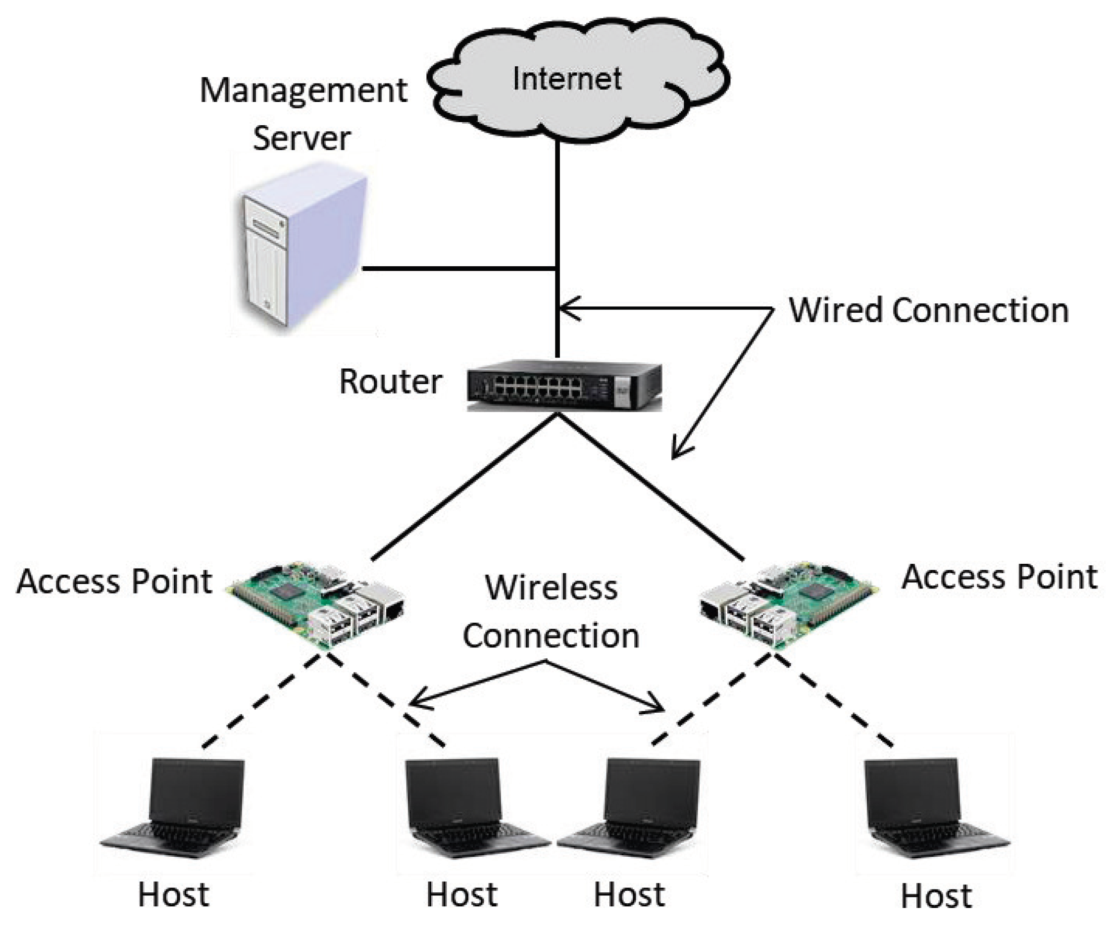
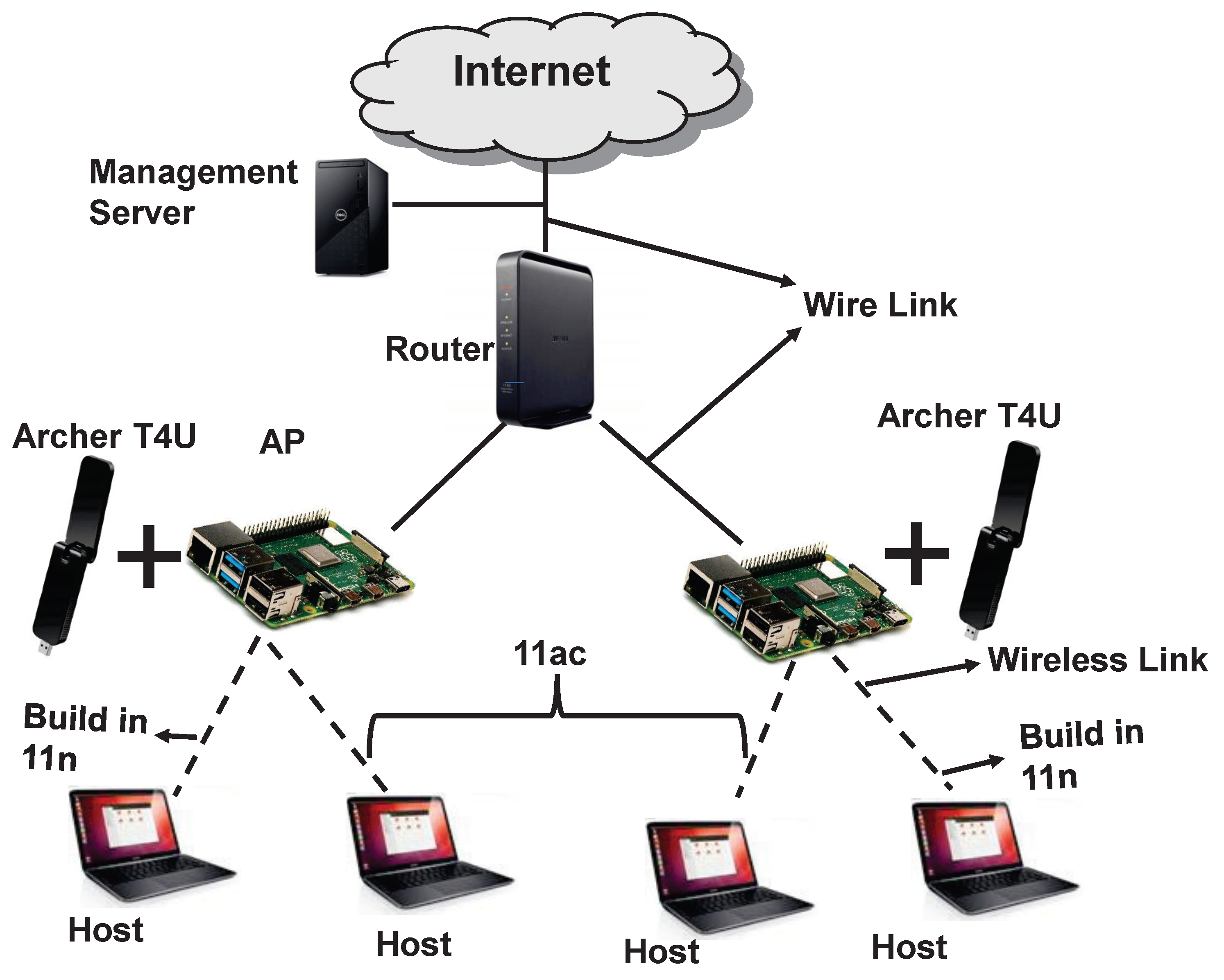
- We evaluated the proposal through both simulations using the WIMENT simulator [36] and experiments using the testbed system in real fields. The testbed system involved a Raspberry Pi with an external Archer T4U for the AP and Linux PCs for the hosts.
2. Related Works
3. Review of Previous Works
3.1. Throughput Estimation Model
3.1.1. Received Signal Strength Estimation
3.1.2. Throughput Estimation from Received Signal Strength
3.1.3. Throughput Reduction Factor
3.1.4. Model Parameter Optimization
3.2. Elastic WLAN System
- It explores all network devices and also collects the information that are required for the active AP configuration algorithm.
- After that, it executes the active AP configuration algorithm through the derived inputs from the previous step. The output of the algorithm contains the list of the active APs, the host associations, and the assigned channels of each active AP.
- Finally, it applies the algorithm output into the network by changing the host associations, activating or deactivating the specified APs, and allocating the channels to the APs.
3.3. Active AP Configuration Algorithm for Dual Interfaces
3.3.1. Formulation
- Inputs:
- number of hosts: H,
- number of APs: N,
- estimated throughput between and for i = 1 to N, j = 1 to H at each interface: ,
- minimum throughput for the association: S,
- number of orthogonal channels (OCs) for each interface: C,
- minimum host throughput: G,
- available total throughput: .
- Outputs:
- set of active APs with dual interfaces,
- set of hosts associated with each interface at every active AP,
- channel assigned to each interface at every active AP.
- Objectives:
- represents the number of active access points (APs) with the dual interfaces to be minimized under the minimum host throughput constraint:
- holding to the first objective, to maximize the minimum average host throughput :where represents the average host throughput for that is given by:where represents the link speed between and ().
- holding to the two objectives, to minimize the total interfered communication time for channel assignments:where is the total communication time, represents the set of the APs interfered with , and indicates the channel assigned to .
- Constraints:
- minimum host throughput: the throughput of any host must be larger than or equal to the minimum host throughput G on average when all the hosts are communicating simultaneously.
- total throughput: the total throughputs for all the hosts must be smaller than or equal to the available total throughput .
- channel assignment: each interface of an AP must be assigned a channel.
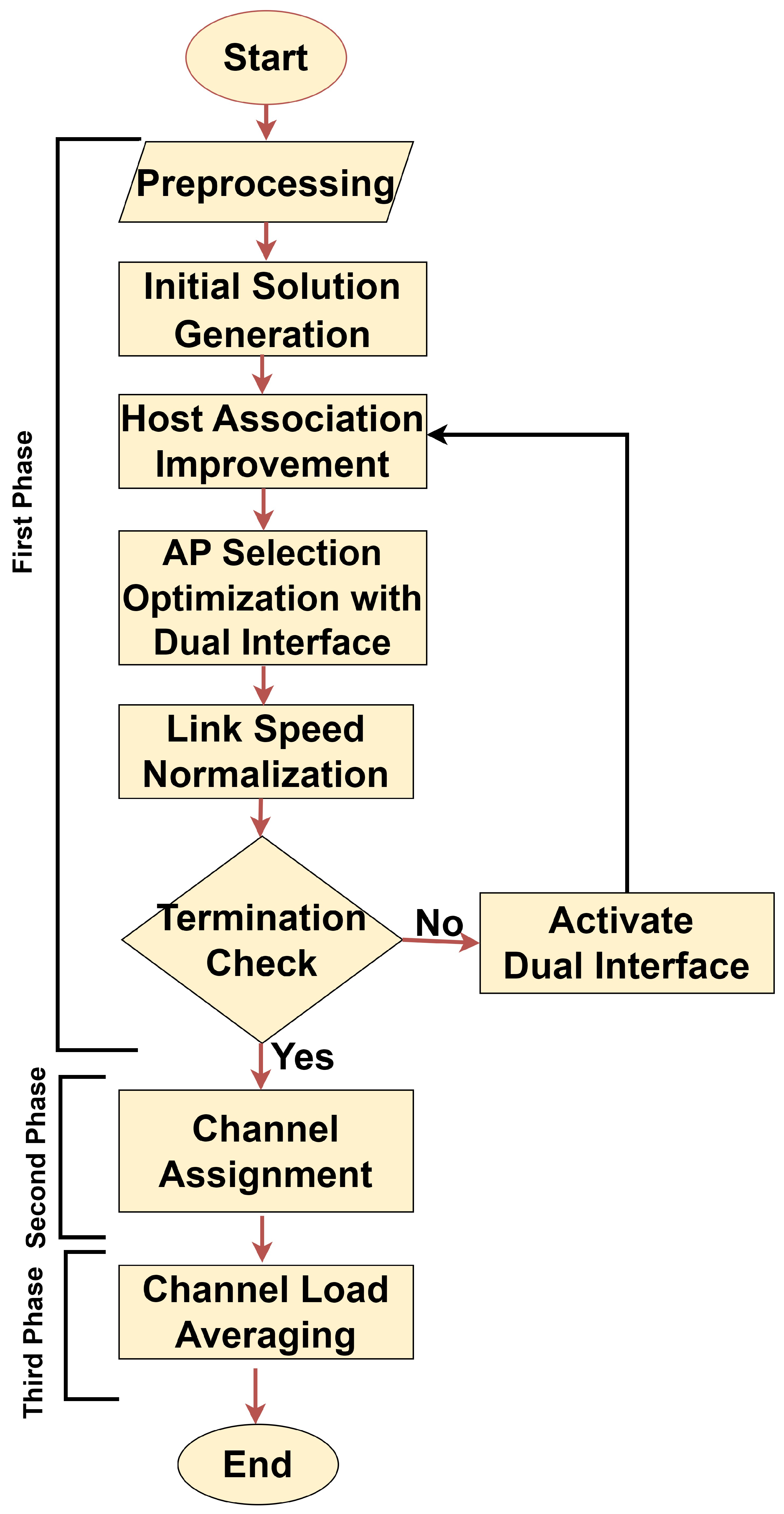
3.3.2. Algorithm Procedure
- First Phase: The first phase of the algorithm selects the active APs with the dual interface and their host associations to minimize and maximize [33].
- (a)
- Preprocessing: Initially, the APs and the hosts locations are used as inputs of the algorithm. The AP locations are selected manually in the network, taking into account the electrical power supply, the coverage, and user demands. The throughput is estimated using the throughput estimation model in Equation (3) for every possible pair of AP and host. In addition, the 11n interface of an AP is chosen as the initial candidate one for any host.
- (b)
- Initial Solution Generation: Greedy algorithm is adopted to calculate the initial solution [51].
- (c)
- Host Association Improvement: The minimum host throughput and the overall throughput in the network are improved by randomly changing the host association according to the procedure in [22].
- (d)
- AP Selection Optimization: This phase optimizes the selection of number of active dual interfaces APs and the AP-host associations in order to further minimize both and using the local search method [52].
- (e)
- Link Speed Normalization: The fairness criterion will be used if the total expected bandwidth is greater than . Next, the speed of the link has been normalized.
- (f)
- Termination Check: If either of the two interfaces for each current AP is not activated, then activate the interface and apply the host association improvement phase. After that, the algorithm will be terminated and proceed to phase 2 if the minimum throughput constraint of the host is satisfied. If not, proceed to the AP selection optimization phase.
- Second Phase: The second phase assigns a channel to each active AP interface to minimize [22].
- (a)
- Preprocessing: The interference and delay conditions of the network are illustrated by a graph.
- (b)
- Interfered AP Set Generation: The set of interfering AP interfaces is found for each AP interface.
- (c)
- Initial Solution Construction: The greedy algorithm is adopted to calculate the the initial solution.
- (d)
- Solution Improvement by Simulated Annealing: Simulated annealing (SA) is the probabilistic optimization technique that can be used to improve the solution by gradually adjusting the solution over time. In our proposal, the SA is used to optimize the channel assignment for each interface of every active AP to improve the performance of the network. The SA procedure is used with the constant temperature for the repeating times , where and are given as the algorithm parameters.
- Third Phase: The third phase averages the loads among the different channels in order to minimize [22].
- (a)
- Initialization: The AP flag is initialized with in every AP. This flag is used to prevent the re-processing of the same AP again.
- (b)
- AP Selection: One OFF flag AP is chosen to move its associated host to a different AP to which a different channel is assigned.
- (c)
- Host Selection: One associated host with the selected AP is selected to perform the AP movement.
- (d)
- Change Application: Finally, the new associated AP is selected for that host.
4. Interface Selection
4.1. Experimental Setup for Interface Selection
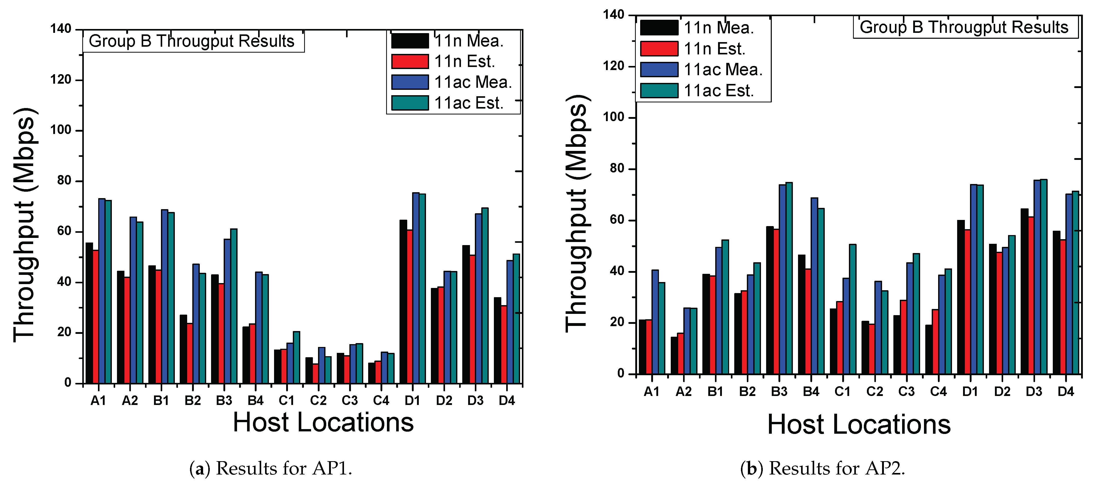
4.2. Throughput Results
5. Modification of Active AP Configuration Algorithm
5.1. Modifications of the Problem Formulation
- Objectives:The average host throughput calculation of in Equation (8) is modified as follows:
5.2. Extension of the Algorithm’s Procedure
- Change the association of each host to the interface of AP which provides the highest throughput using Equation (4) within the associable AP interfaces. At this stage, compute the cost function and keep it as the best found cost function, .
- Find the interface of AP that provides the lowest host throughput using Equation (7). Then, make the modifiable hosts list that are associated with the AP interface, which can be connected with another AP interfaces.
- Choose one host at random from the list of modifiable hosts. Then, this host is associated at random with other associable active AP interface. Compute the new cost function .
- Replace with the newly found , if , and retain the new AP-host association. If not, go back to the previous association and select the best cost function .
6. Evaluations
6.1. Simulation Setup
6.2. Experimental Setup
- $
- #40 MHz for 11n
- $
- rsn_pairwise=CCMP
- $
- ht_capab=[HT40+][SHORT-GI-20][SHORT-GI-40][DSSS_CCK-40][MAX−AMSDU−3839]
- $
- #40 MHz for 11ac
- $
- rsn_pairwise=CCMP
- $
- vht_capab=[MAX-MPDU-3895][SHORT-GI-80][SU-BEAMFORMEE]
- The server obtains active all the APs in the network.
- It collects the information of the connected devices in the network using arp-scan-tool in Linux, which includes the IP and MAC addresses of the APs and the hosts.
- It collects the receiving signal strength (RSS) at each host from each AP using nm-tool.
- It converts the RSS to the throughput using the sigmoid function in [23].
- It executes the active AP configuration algorithm using the inputs derived in the previous steps and obtains the algorithm output that consists of the number of active APs, the host associations, and the channels assigned to the active APs.
- It activates or deactivates the APs in the network according to the algorithm output using the following command.$ sudo /etc/init.d/hostapd start$ sudo /etc/init.d/hostapd stop
- It changes the associations of the hosts with the APs according to the algorithm output using nmcli-tool.
- It assigns the channels to the APs according to the algorithm output using sed-tool.
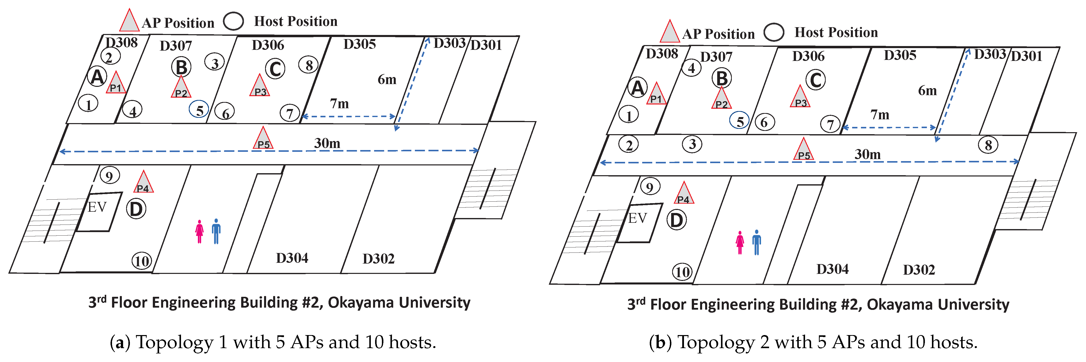
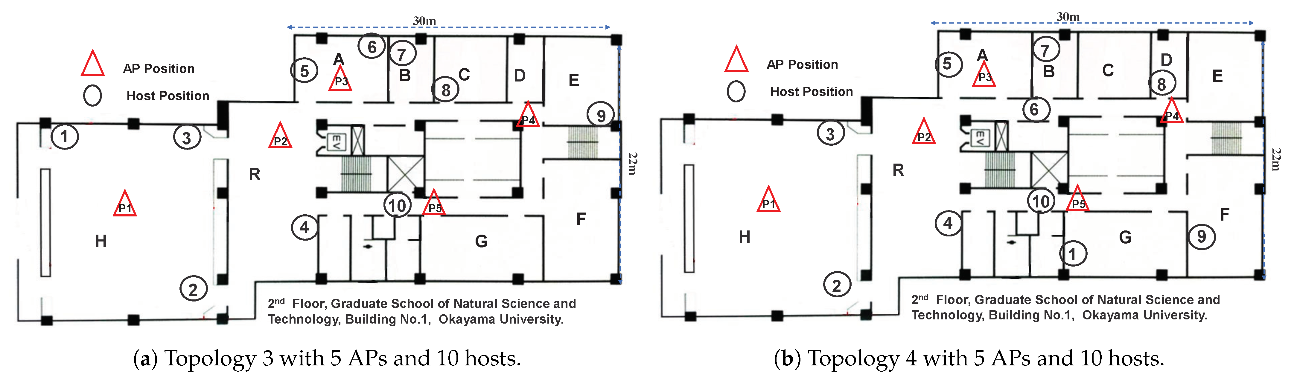
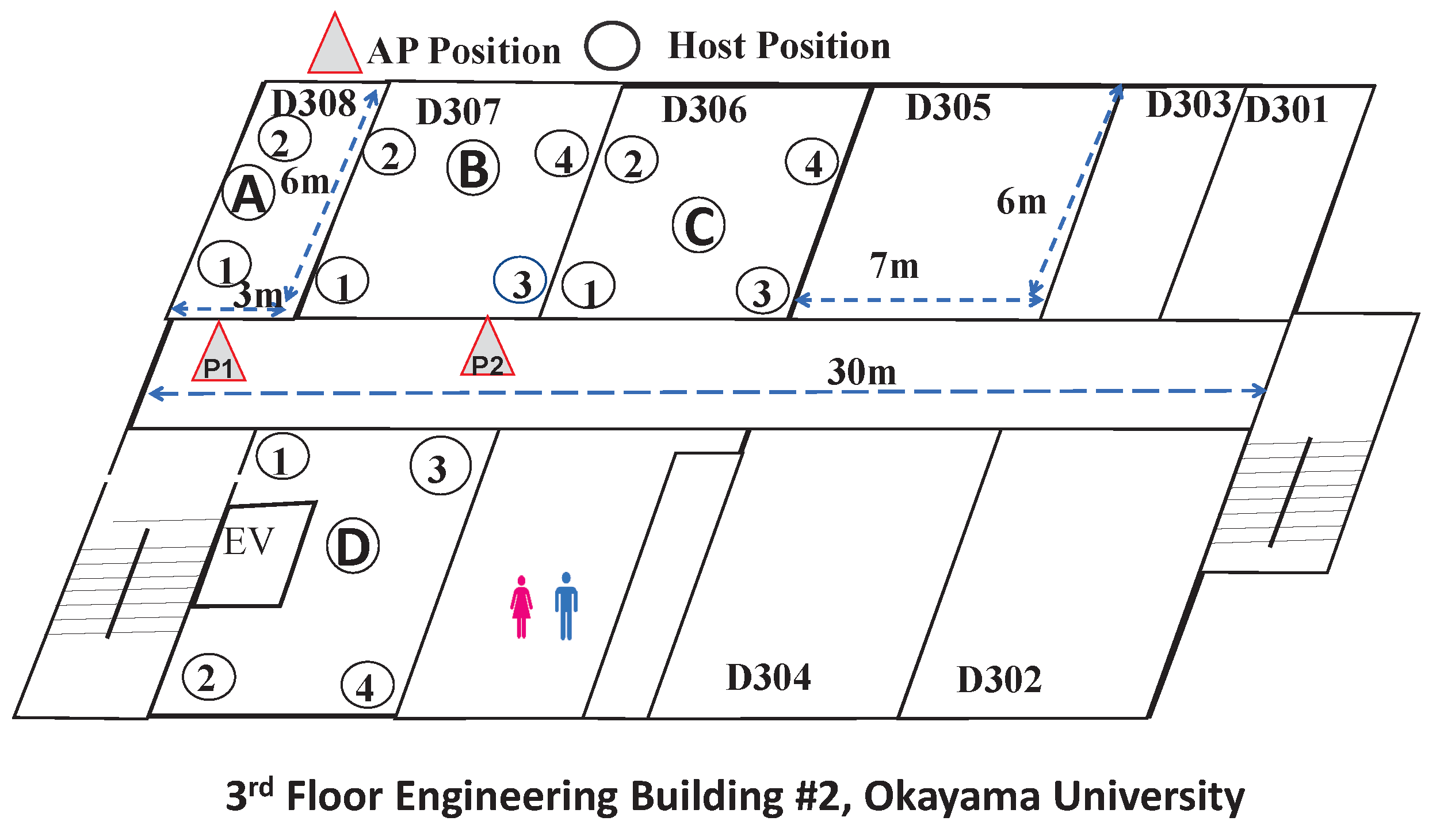
6.3. Network Fields
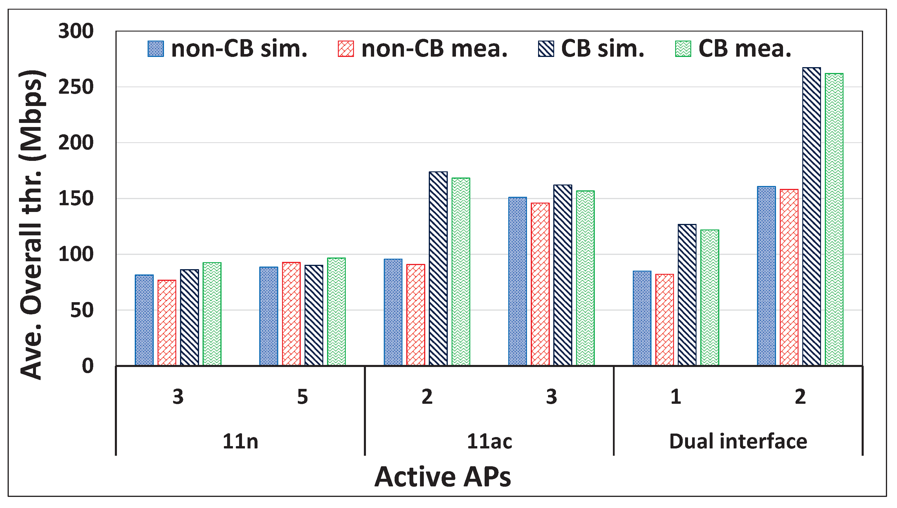
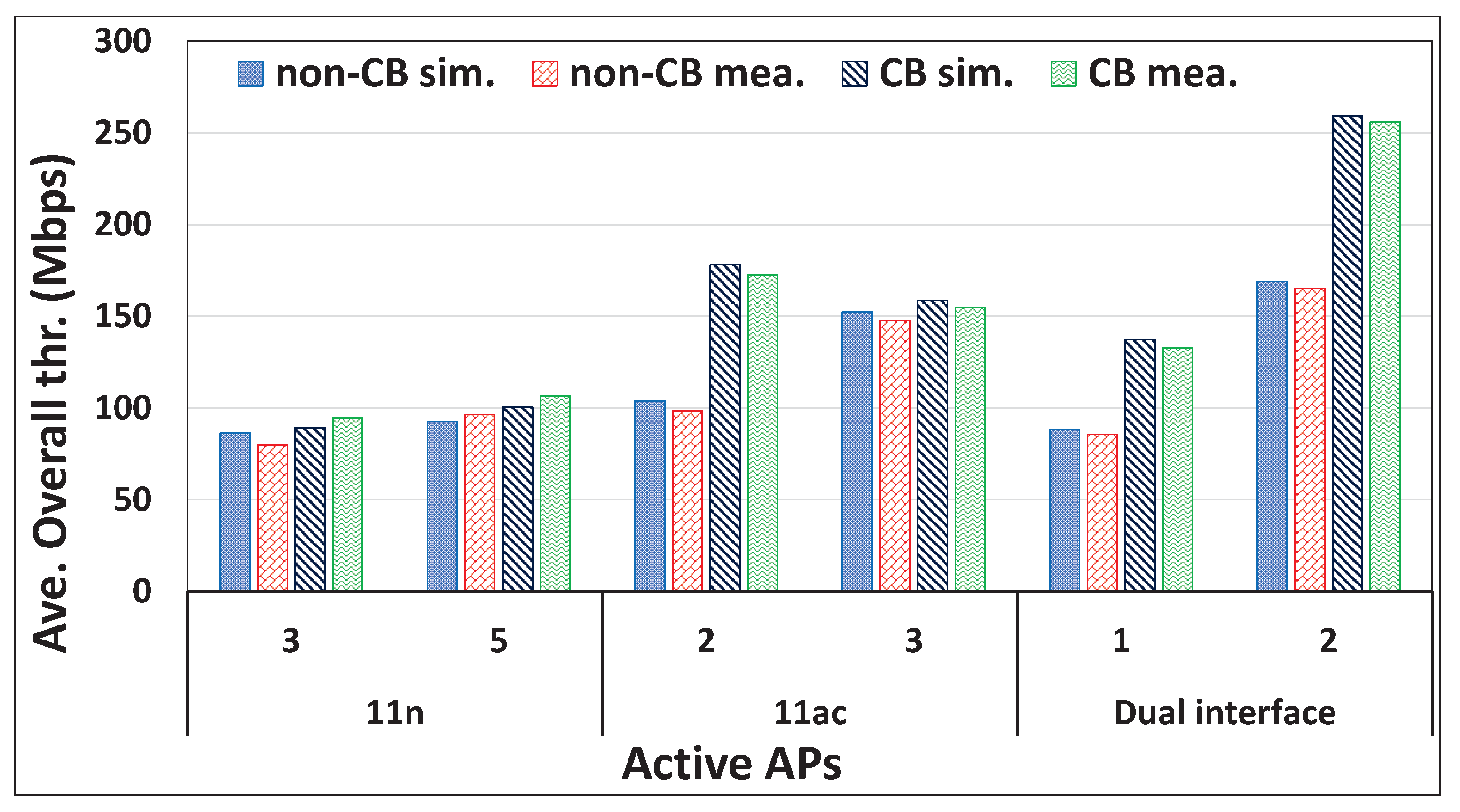
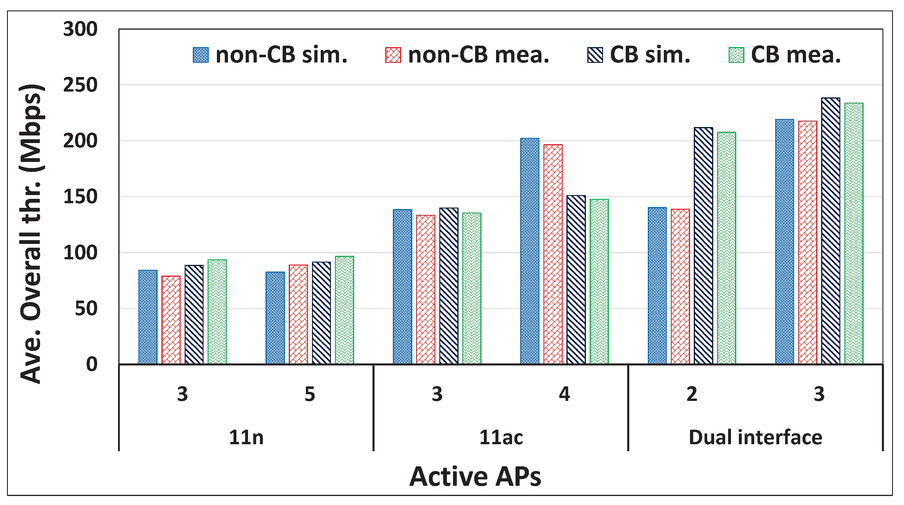
6.4. Results and Discussions
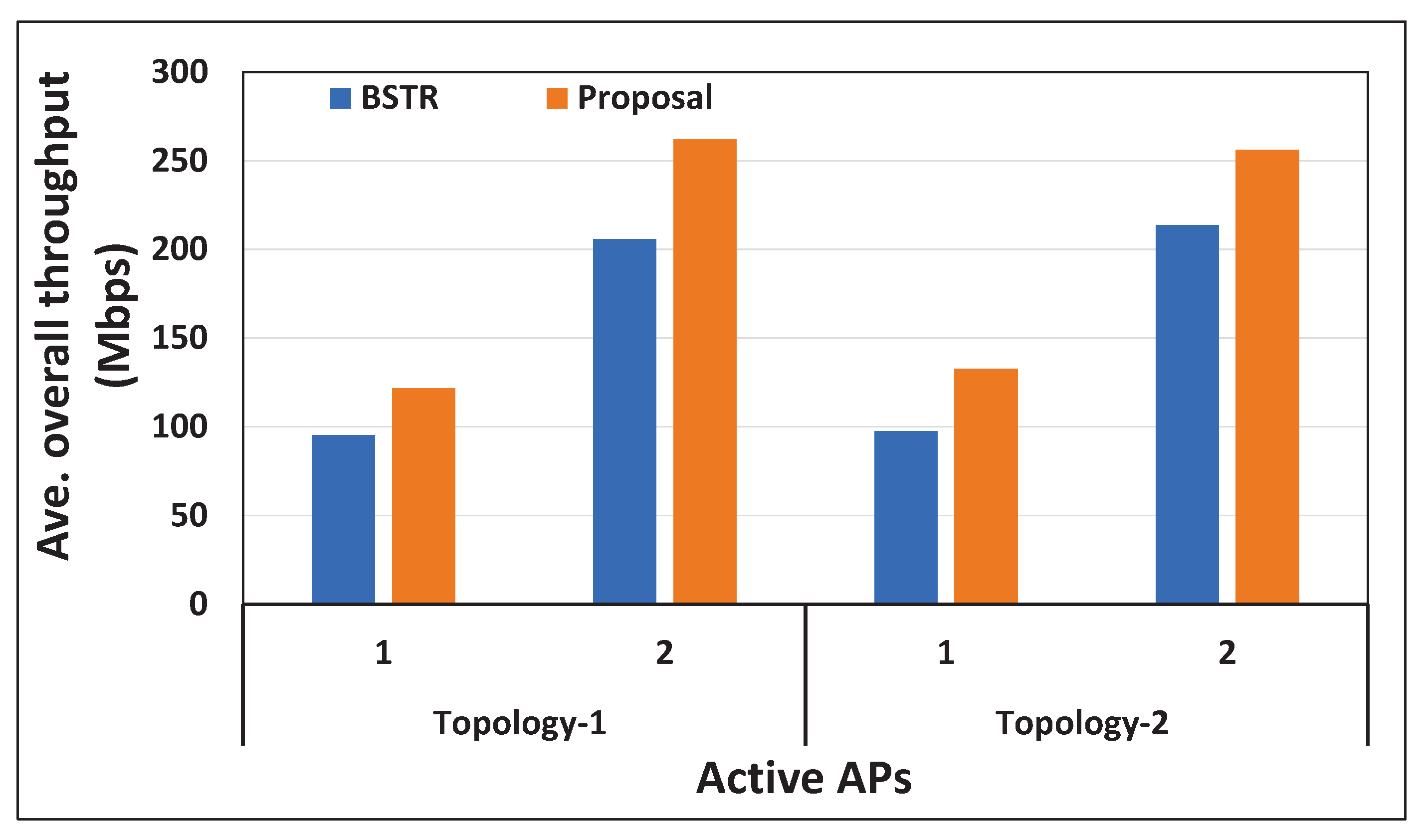
6.5. Comparisons with Previous Studies
7. Conclusions
Author Contributions
Funding
Data Availability Statement
Conflicts of Interest
References
- Sadhu, P.K.; Yanambaka, V.P.; Abdelgawad, A. Internet of Things: Security and solutions survey. Sensors 2022, 22, 7433. [Google Scholar] [CrossRef] [PubMed]
- Ahsan, M.; Teay, S.H.; Sayem, A.S.M.; Albarbar, A. Smart clothing framework for health monitoring applications. Signals 2022, 3, 113–145. [Google Scholar] [CrossRef]
- Ahmad, K.; Maabreh, M.; Ghaly, M.; Khan, K.; Qadir, J.; Al-Fuqaha, A. Developing future human-centered smart cities: Critical analysis of smart city security, data management, and ethical challenges. Comput. Sci. Rev. 2022, 43, 100452. [Google Scholar] [CrossRef]
- Sinha, B.B.; Dhanalakshmi, R. Recent advancements and challenges of Internet of Things in smart agriculture: A survey. Future Gener. Comput. Syst. 2022, 126, 169–184. [Google Scholar] [CrossRef]
- Mohamad Jawad, H.H.; Bin Hassan, Z.; Zaidan, B.B.; Mohammed Jawad, F.H.; Mohamed Jawad, D.H.; Alredany, W.H.D. A systematic literature review of enabling IoT in healthcare: Motivations, challenges, and recommendations. Electronics 2022, 11, 3223. [Google Scholar] [CrossRef]
- Mocrii, D.; Chen, Y.; Musilek, P. IoT-based smart homes: A review of system architecture, software, communications, privacy and security. Int. Things 2018, 1, 81–98. [Google Scholar] [CrossRef]
- Agyemang, J.O.; Kponyo, J.J.; Klogo, G.S.; Boateng, J.O. Lightweight rogue access point detection algorithm for WiFi-enabled Internet of Things (IoT) devices. Int. Things 2020, 11, 100200. [Google Scholar] [CrossRef]
- Munene, K.I.; Funabiki, N.; Rahman, M.M.; Briantoro, H.; Roy, S.C.; Kuribayashi, M. A throughput drop estimation model and its application to joint optimization of transmission power, frequency channel, and channel bonding in IEEE 802.11 n WLAN for large-scale IoT environments. Int. Things 2022, 20, 100583. [Google Scholar] [CrossRef]
- Brito, T.; Pereira, A.I.; Lima, J.; Valente, A. Wireless sensor network for ignitions detection: An IoT approach. Electronics 2020, 9, 893. [Google Scholar] [CrossRef]
- Gupta, B.B.; Quamara, M. An overview of Internet of Things (IoT): Architectural aspects, challenges, and protocols. Concurr. Comput. Pract. Exper. 2020, 32, e4946. [Google Scholar] [CrossRef]
- Prasad, S.B.; Madhumathy, P. Long term evolution for secured smart railway communications using internet of things. In Machine Learning Algorithms for Industrial Applications; Das, S., Das, S., Dey, N., Hassanien, A.E., Eds.; Springer: Cham, Switzerland, 2021; pp. 285–300. ISBN 978-3-030-50641-4. [Google Scholar]
- Hong, H.; Kim, Y.Y.; Kim, R.Y. A low-power WLAN communication scheme for IoT WLAN devices using wake-up receivers. Appl. Sci. 2018, 8, 72. [Google Scholar] [CrossRef] [Green Version]
- Islam, M.M.; Funabiki, N.; Sudibyo, R.W.; Munene, K.I.; Kao, W.C. A dynamic access-point transmission power minimization method using PI feedback control in elastic WLAN system for IoT applications. Int. Things 2019, 8, 100089. [Google Scholar] [CrossRef]
- Islam, M.M. A Study of Dynamic Access-Point Configuration and Power Minimization in Elastic Wireless Local-Area Network System. Ph.D. Thesis, Graduate School of Natural Science and Technology, Okayama University, Okayama, Japan, 2019. [Google Scholar]
- Crow, B.P.; Widjaja, I.; Kim, J.G.; Sakai, P.T. IEEE 802.11 wireless local area networks. IEEE Commun. Mag. 1997, 35, 116–126. [Google Scholar] [CrossRef]
- Gast, M. 802.11 n: A Survival Guide; O’Reilly Media, Inc.: Sebastopol, CA, USA, 2012; ISBN 9781449312046. [Google Scholar]
- Kassa, L.; Davis, M.; Cai, J.; Deng, J. A new adaptive frame aggregation method for downlink WLAN MU-MIMO channels. J. Commun. 2021, 16, 311–322. [Google Scholar] [CrossRef]
- Kang, S.L.; Chen, G.Y.H.; Rogers, J. Wireless LAN access point location planning. In Proceedings of the Institute of Industrial Engineers Asian Conference, Taipei, Taiwan, 18–20 July 2013; pp. 907–914. [Google Scholar]
- Al Mamun, M.S.; Islam, M.E.; Funabiki, N.; Kuribayashi, M.; Lai, I.W. An active access-point configuration algorithm for elastic wireless local-area network system using heterogeneous devices. Int. J. Netw. Comput. 2016, 6, 395–419. [Google Scholar]
- Kim, Y.; Kim, M.S.; Lee, S.; Griffith, D.; Golmie, N. AP selection algorithm with adaptive CCAT for dense wireless networks. In Proceedings of the IEEE Wireless Communications and Networking Conference (WCNC), San Francisco, CA, USA, 19–22 March 2017; pp. 1–6. [Google Scholar]
- Munene, K.I.; Funabiki, N.; Islam, M.M.; Kuribayashi, M.; Al Mamun, M.S.; Kao, W.C. An extension of throughput drop estimation model for three-link concurrent communications under partially overlapping channels and channel bonding in IEEE 802.11 n WLAN. Adv. Sci. Technol. Eng. Syst. J. 2019, 4, 94–105. [Google Scholar] [CrossRef] [Green Version]
- Al Mamun, M.S.; Funabiki, N.; Lwin, K.S.; Islam, M.E.; Kao, W.C. A channel assignment extension of active access-point configuration algorithm for elastic WLAN system and its implementation using Raspberry Pi. Int. J. Netw. Comput. 2017, 7, 248–270. [Google Scholar] [CrossRef] [Green Version]
- Funabiki, N.; Taniguchi, C.; Lwin, K.S.; Zaw, K.K.; Kao, W.C. A parameter optimization tool and its application to throughput estimation model for wireless LAN. In Proceedings of the Conference on Complex, Intelligent, and Software Intensive Systems, Turin, Italy, 10–13 July 2017; pp. 701–710. [Google Scholar]
- Lwin, K.S.; Funabiki, N.; Taniguchi, C.; Zaw, K.K.; Al Mamun, M.S.; Kuribayashi, M.; Kao, W.C. A minimax approach for access point setup optimization in IEEE 802.11 n wireless networks. Int. J. Netw. Comput. 2017, 7, 187–207. [Google Scholar]
- Deek, L.; Garcia-Villegas, E.; Belding, E.; Lee, S.J.; Almeroth, K. The impact of channel bonding on 802.11 n network management. In Proceedings of the Seventh Conference on emerging Networking EXperiments and Technologies, Tokyo, Japan, 6–9 December 2011; pp. 1–12. [Google Scholar]
- Han, M.; Khairy, S.; Cai, L.X.; Cheng, Y. Performance analysis of opportunistic channel bonding in multi-channel WLANs. In Proceedings of the IEEE Global Communications Conference (GLOBECOM), Washington, DC, USA, 4–8 December 2016; pp. 1–6. [Google Scholar]
- Gast, M.S. 802.11 ac: A Survival Guide: Wi-Fi at Gigabit and Beyond, 1st ed.; O’Reilly Media, Inc.: Sebastopol, CA, USA, 2013. [Google Scholar]
- Daldoul, Y.; Meddour, D.E.; Ksentini, A. IEEE 802.11 ac: Effect of channel bonding on spectrum utilization in dense environments. In Proceedings of the IEEE International Conference on Communications (ICC), Paris, France, 21–25 May 2017; pp. 1–6. [Google Scholar]
- Khorov, E.; Kiryanov, A.; Lyakhov, A.; Bianchi, G. A tutorial on IEEE 802.11 ax high efficiency WLANs. IEEE Commun. Surv. Tuts. 2019, 21, 197–216. [Google Scholar] [CrossRef]
- BUFFALO WI-U3-1200AX2. Available online: https://www.buffalo.jp/product/detail/wi-u3-1200ax2.html (accessed on 21 February 2023).
- National Instrument. Introduction to Wireless LAN Measurements from 802.11a to 802.11ac. 2018. Available online: http://download.ni.com/evaluation/rf/Introduction_to_WLAN_Testing.pdf (accessed on 24 November 2022).
- Barrachina-Muñoz, S.; Wilhelmi, F.; Bellalta, B. To overlap or not to overlap: Enabling channel bonding in high-density WLANs. Comput. Netw. 2019, 152, 40–53. [Google Scholar] [CrossRef] [Green Version]
- Roy, S.C.; Funabik, N.; Munene, K.I.; Rahman, M.M.; Kuribayashi, M. An extension of active access-point configuration algorithm to IEEE 802.11n and 11ac dual interfaces in wireless local-area network. Int. J. Future Comput. Commun. 2022, 11, 18–26. [Google Scholar]
- Raspberry, Pi. Available online: http://raspberrypi.org (accessed on 24 November 2022).
- Archer T4U. Available online: https://www.tp-link.com/jp/home-networking/adapter/archer-t4u/ (accessed on 24 November 2022).
- Funabiki, N. Wireless Mesh Networks; InTech-Open: London, UK, 2011; Available online: https://www.intechopen.com/books/26 (accessed on 24 November 2022).
- Yan, D.; Zhang, C.; Liao, H.; Yang, L.; Li, P.; Yang, G. AP deployment research based on physical distance and channel isolation. Abst. Appl. Analy. 2014, 2014, 941547. [Google Scholar] [CrossRef] [Green Version]
- Tang, S.; Ma, L.; Xu, Y. A novel AP placement algorithm based on user distribution for indoor WLAN system. China Commun. 2016, 13, 108–118. [Google Scholar] [CrossRef]
- Tian, Y.; Huang, B.; Jia, B.; Zhao, L. Optimizing wifi ap placement for both localization and coverage. In Proceedings of the International Conference on Algorithms and Architectures for Parallel Processing, Guangzhou, China, 15–17 November 2018; pp. 489–503. [Google Scholar]
- Wan, X.; Guan, X.; Shen, Y.; Choi, B.Y. Optimal user association in hybrid WLANs under bandwidth constraints. In Proceedings of the IEEE International Smart Cities Conference (ISC2), Kansas City, MO, USA, 16–19 September 2018; pp. 1–8. [Google Scholar]
- Islam, M.T.; Choi, B.Y. Jointly maximizing throughput and utilization for dense enterprise WLANs. In Proceedings of the IEEE International Smart Cities Conference (ISC2), Casablanca, Morocco, 14–17 October 2019; pp. 753–759. [Google Scholar]
- Zhi, Z.; Wu, J.; Meng, X.; Yao, M.; Hu, Q.; Tang, Z. AP deployment optimization in non-uniform service areas: A genetic algorithm approach. In Proceedings of the IEEE 90th Vehicular Technology Conference (VTC2019-Fall), Honolulu, HI, USA, 22–25 September 2019; pp. 1–5. [Google Scholar]
- Liu, P.; Meng, X.; Wu, J.; Yao, M.; Tang, Z. AP deployment optimization for WLAN: A fruit fly optimization approach. In Proceedings of the IEEE/CIC International Conference on Communications in China (ICCC), Changchun, China, 16–18 August 2018; pp. 478–483. [Google Scholar]
- Liu, J.; Aoki, T.; Li, Z.; Pei, T.; Choi, Y.J.; Nguyen, K.; Sekiya, H. Throughput analysis of IEEE 802.11 WLANs with inter-network interference. Appl. Sci. 2020, 10, 2192. [Google Scholar] [CrossRef] [Green Version]
- Kong, Z.; Wu, D.; Jin, X.; Cen, S.; Dong, F. Improved AP deployment optimization scheme based on multi-objective particle swarm optimization algorithm. KSII Trans. Internet Infor. Syst. (TIIS) 2021, 15, 1568–1589. [Google Scholar]
- Qiu, S.; Chu, X.; Leung, Y.W.; Ng, J.K.Y. Joint access point placement and power-channel-resource-unit assignment for IEEE 802.11 ax-Based dense WiFi network with QoS requirements. IEEE Trans. Mob. Comput. 2021. [Google Scholar] [CrossRef]
- Abusubaih, M.A.; Eddin, S.N.; Khamayseh, A. IEEE 802.11n dual band access points for boosting the performance of heterogeneous WiFi networks. In Proceedings of the 8th ACM Workshop on Performance Monitoring and Measurement of Heterogeneous Wireless and Wired Networks, New York, NY, USA, 3–8 November 2013; pp. 1–4. [Google Scholar]
- Nishat, K.; Javed, F.; Salman, S.; Yaseen, N.; Fida, A.; Qazi, I.A. Slickfi: A service differentiation scheme for high-speed wlans using dual radio aps. In Proceedings of the 12th International on Conference on Emerging Networking EXperiments and Technologies (CoNEXT’16), New York, NY, USA, 12–15 December 2016; pp. 177–189. [Google Scholar]
- Faria, D.B. Modeling Signal Attenuation in IEEE 802.11 Wireless LANs—Vol. 1. 2005. Available online: http://www-cs-students.stanford.edu/~dbfaria/files/faria-TR-KP06-0118.pdf (accessed on 24 November 2022).
- Lu, T.; Funabiki, N.; Munene, K.I.; Sudibyo, R.W. An improved throughput estimation model for concurrent communications of multiple hosts in wireless local-area network. In Proceedings of the IEEE Hiroshima Section Student Symposium (HISS), Okayama, Japan, 30 November–1 December 2019; pp. 360–363. [Google Scholar]
- Wolsey, L.A. An analysis of the greedy algorithm for the submodular set covering problem. Combinatorica 1982, 2, 385–393. [Google Scholar] [CrossRef]
- Williamson, D.P.; Shmoys, D.B. The Design of Approximation Algorithms, 1st ed.; Cambridge University Press: Cambridge, UK, 2011. [Google Scholar]
- Debnath, S.K.; Funabiki, N.; Lwin, K.S.; Al Mamun, M.S.; Sudibyo, R.W.; Huda, S. Raspberry Pi configuration for access-point and its throughput measurements in IEEE802.11n wireless networks. IEICE Tech. Rep. 2016, 116, 101–106. [Google Scholar]
- Hostapd. Available online: https://w1.fi/hostapd/ (accessed on 24 November 2022).
- Iperf—The TCP, UDP and SCTP Network Bandwidth Measurement Tool. Available online: https://iperf.fr/ (accessed on 24 November 2022).
- Islam, M.E.; Funabiki, N.; Lwin, K.S.; Mamun, M.S.A.; Debnath, S.K.; Kuribayashi, M. Performance evaluations of elastic WLAN testbed. IEICE Gen. Conf. 2016, S76–S77. [Google Scholar]
- Sudibyo, R.W.; Funabiki, N.; Kuribayashi, M.; Munene, K.I.; Islam, M.M.; Kao, W.C. A TCP fairness control method for two-host concurrent communications in elastic WLAN system using Raspberry Pi access-point. In Proceedings of the 2nd International Conference on Communication Engineering and Technology (ICCET), Nagoya, Japan, 12–15 April 2019; pp. 76–80. [Google Scholar]
- Islam, M.M.; Funabiki, N.; Kuribayashi, M.; Debnath, S.K.; Munene, K.I.; Lwin, K.S.; Sudibyo, R.W. Dynamic access-point configuration approach for elastic wireless local-area network system and its implementation using Raspberry Pi. Int. J. Netw. Comput. 2018, 8, 254–281. [Google Scholar] [CrossRef] [Green Version]
- Qualcomm. Band-Steering for Dual-Band Wi-Fi Access Points. Available online: https://www.qualcomm.com/content/dam/qcomm-martech/dm-assets/documents/qc_band_steering_wp.pdf (accessed on 8 February 2023).


| Reference | Goal | Method | Satisfy USER Requirement | Dense Wi-Fi | Dual Interface | Minimize AP Cost | Evaluation |
|---|---|---|---|---|---|---|---|
| proposal | minimize the number of active APs | greedy algorithm and local search method | yes | yes | yes | yes | simulation and testbed experiment |
| [37] | optimizes the APs placement | genetic algorithm | no | yes | no | no | simulation |
| [38] | adjust the AP deployment | fuzzy C-clustering | yes | yes | no | yes | simulation |
| [39] | minimize the number of APs | genetic algorithm and cramer-rao lower bound method | yes | yes | no | yes | simulation |
| [40] | optimal userassociation and maximizes the total network throughput | polynomial-time algorithm | yes | yes | no | no | simulation |
| [41] | maximizes the network throughput and AP utilization | rounding and bandwidth allocation algorithm | yes | no | no | no | simulation |
| [42] | minimize the number of APs | genetic algorithm | no | yes | no | yes | simulation |
| [43] | minimize the number of APs | fruit fly optimization algorithm | no | yes | no | yes | simulation |
| [44] | throughput analysis take into account the effects of inter-network interference | airtime concept | no | yes | no | no | simulation |
| [45] | minimize the number of APs | multi-objective particle swarm optimization (MOPSO) algorithm and greedyalgorithm | yes | no | yes | simulation | |
| [46] | minimize the number of APs | polynomial time heuristic algorithm | yes | yes | no | yes | simulation |
| [47] | investigate the ability of IEEE 802.11n dual-band APs | - | no | no | no | no | testbed experiment |
| [48] | maximize the performance of real-time application and network throughput | QoS differentiation scheme (Slickfi) | no | no | yes | yes | testbed experiment |
| Parameter | Field #1 | Field #2 | ||||
|---|---|---|---|---|---|---|
| Group A | Group B | 11n | 11ac | |||
| 11n | 11ac | 11n | 11ac | |||
| P1 | −28.9 | −31.0 | −31.1 | −36.1 | −28.5 | −30.5 |
| 2.20 | 2.15 | 1.6 | 2.18 | 1.7 | 2.0 | |
| W1 | 7.21 | 2.1 | 6.5 | 4.2 | 6.5 | 2.3 |
| W2 | 6.9 | 8.5 | 3.5 | 4.1 | 4.2 | 6.4 |
| W3 | 3.4 | 3.7 | 3.5 | 4.4 | 3.1 | 1.8 |
| W4 | 4.7 | 1.8 | 3.5 | 4.55 | 1.5 | 4.2 |
| W5 | 2.11 | 7.0 | 2.5 | 2.1 | 2 | 4.3 |
| W6 | 2.5 | 1.5 | 1.5 | 1.5 | 2 | 5.3 |
| a | 63.5 | 133 | 66 | 77 | 65 | 134.5 |
| b | 62 | 58 | 70 | 54.1 | 62 | 58.5 |
| c | 6.78 | 6.30 | 5.2 | 5.2 | 6.78 | 6.25 |
| simulator | WIMNET |
| CPU | Intel Core i7 |
| memory | 8 GB |
| OS | Ubuntu LTS 14.04 |
| Parameter | Values |
|---|---|
| packet size | 1500 bytes |
| max. transmission rate | 150 Mbit/s |
| propagation model | log distance path loss model |
| rate adaptation algorithm | link speed estimation model [24] |
| carrier sense threshold | dBm |
| transmission power | 19 dBm |
| collision threshold | 10 |
| RTS/CTS | yes |
| Access Point | |
|---|---|
| model | Raspberry Pi 4B |
| CPU | Broadcom BCM2711 @1.5 GHz |
| RAM | 8 GB LPDDR4-3200 SDRAM |
| Operating System | Linux Raspbian |
| Software | hostapd V 2.10 |
| External NIC | Archer T4U V3.0 AC1300 |
| server PC | |
| Model | Fujitsu Lifebook S761/C |
| CPU | Intel Core i5-2520M @2.5 GHz |
| RAM | 4 GB DDR3 1333 MHz |
| Operating System | Linux Ubuntu 14.04 LTS (kernel 3.13.0-57) |
| Software | iperf 2.0.5 |
| host PC | |
| Model | 1. Toshiba Dynabook R731/B |
| 2. Toshiba Dynabook R734/K | |
| 3. Fujitsu Lifebook S761/C | |
| CPU | 1. Intel Core i5-2520M @2.5 GHz |
| 2. Intel Core i5-4300M @2.6 GHz | |
| 3. Intel Core i5-2520M @2.5 GHz | |
| RAM | 4 GB DDR3 1333MHz |
| Operating System | Linux Ubuntu 14.04 LTS (kernel 3.13.0-57) |
| Software | iperf 2.0.5 |
| Exp. Field | Topology | Min. Host Thro. Cons. G (Mbps) | Single Interface | Dual Interface | |||||||
|---|---|---|---|---|---|---|---|---|---|---|---|
| 11n | 11ac | ||||||||||
| Total Active APs | Ave. Min. Host Thro. (Mbps) | Total Active APs | Ave. Min. Host Thro. (Mbps) | Total Active APs | Ave. Min. Host Thro. (Mbps) | ||||||
| both | sim. | mea. | both | sim. | mea. | both | sim. | mea. | |||
| field #1 | 1 | 10 | 3 | 13.32 | 12.56 | 2 | 14.78 | 13.66 | 1 | 12.32 | 11.47 |
| 25 | 5 | 26.34 | 25.02 | 3 | 26.64 | 25.08 | 2 | 26.65 | 25.19 | ||
| 2 | 10 | 3 | 13.58 | 12.77 | 2 | 16.54 | 14.84 | 1 | 13.09 | 12.19 | |
| 25 | 5 | 25.13 | 24.78 | 3 | 26.23 | 25.09 | 2 | 26.89 | 25.37 | ||
| field #2 | 3 | 10 | 3 | 12.93 | 11.76 | 2 | 12.50 | 11.36 | 1 | 12.34 | 11.53 |
| 25 | 5 | 25.01 | 24.04 | 4 | 31.18 | 29.63 | 3 | 37.71 | 35.83 | ||
| 4 | 10 | 3 | 13.45 | 12.66 | 3 | 17.39 | 15.73 | 2 | 19.94 | 18.25 | |
| 25 | 5 | 23.80 | 22.85 | 4 | 27.71 | 26.02 | 3 | 36.55 | 34.76 | ||
| Exp. Field | Topology | Minimum Host Throughput Constraint G (Mbps) | Dual Interface | ||||
|---|---|---|---|---|---|---|---|
| Total Active APs | Average Minimum Host Throughput (Mbps) | Average Overall Throughput (Mbps) | |||||
| both | sim. | mea. | sim. | mea. | |||
| field #1 | 1 | 20 | 2 | 26.65 | 25.19 | 267.19 | 261.93 |
| 30 | 3 | 37.88 | 35.92 | 235.24 | 231.06 | ||
| 2 | 20 | 2 | 26.89 | 25.37 | 259.12 | 255.97 | |
| 30 | 3 | 36.38 | 34.02 | 225.77 | 220.63 | ||
| field #2 | 3 | 20 | 2 | 24.22 | 22.32 | 266.34 | 259.36 |
| 40 | 4 | 45.72 | 42.36 | 215.75 | 210.36 | ||
| 4 | 20 | 3 | 36.55 | 34.76 | 238.45 | 233.93 | |
| 40 | 4 | 43.67 | 40.92 | 222.35 | 217.21 | ||
| Exp. Field | Topology | Min. Host Thro. Cons. G (Mbps) | Single Interface | Dual Interface | |||||||
|---|---|---|---|---|---|---|---|---|---|---|---|
| 11n | 11ac | ||||||||||
| Total Active APs | Ave. Min. Host Thro. (Mbps) | Total Active APs | Ave. Min. Host Thro. (Mbps) | Total Active APs | Ave. Min. Host Thro. (Mbps) | ||||||
| both | sim. | mea. | both | sim. | mea. | both | sim. | mea. | |||
| field #1 | 1 | 5 | 3 | 8.20 | 6.96 | 2 | 8.78 | 7.14 | 1 | 8.14 | 7.82 |
| 15 | 5 | 14.05 | 12.26 | 3 | 15.12 | 13.25 | 2 | 16.11 | 15.16 | ||
| 2 | 5 | 3 | 8.15 | 6.93 | 2 | 9.21 | 7.96 | 1 | 8.14 | 7.02 | |
| 15 | 5 | 14.46 | 12.98 | 3 | 15.65 | 14.42 | 2 | 16.43 | 14.88 | ||
| field #2 | 3 | 5 | 3 | 7.95 | 6.90 | 2 | 9.21 | 8.11 | 1 | 8.01 | 7.12 |
| 15 | 5 | 15.05 | 13.81 | 4 | 17.79 | 16.08 | 3 | 19.95 | 17.96 | ||
| 4 | 5 | 3 | 8.34 | 7.07 | 3 | 12.89 | 11.06 | 2 | 13.24 | 12.10 | |
| 15 | 5 | 15.97 | 13.89 | 4 | 19.04 | 17.35 | 3 | 21.15 | 20.67 | ||
Disclaimer/Publisher’s Note: The statements, opinions and data contained in all publications are solely those of the individual author(s) and contributor(s) and not of MDPI and/or the editor(s). MDPI and/or the editor(s) disclaim responsibility for any injury to people or property resulting from any ideas, methods, instructions or products referred to in the content. |
© 2023 by the authors. Licensee MDPI, Basel, Switzerland. This article is an open access article distributed under the terms and conditions of the Creative Commons Attribution (CC BY) license (https://creativecommons.org/licenses/by/4.0/).
Share and Cite
Roy, S.C.; Funabiki, N.; Rahman, M.M.; Wu, B.; Kuribayashi, M.; Kao, W.-C. A Study of the Active Access-Point Configuration Algorithm under Channel Bonding to Dual IEEE 802.11n and 11ac Interfaces in an Elastic WLAN System for IoT Applications. Signals 2023, 4, 274-296. https://doi.org/10.3390/signals4020015
Roy SC, Funabiki N, Rahman MM, Wu B, Kuribayashi M, Kao W-C. A Study of the Active Access-Point Configuration Algorithm under Channel Bonding to Dual IEEE 802.11n and 11ac Interfaces in an Elastic WLAN System for IoT Applications. Signals. 2023; 4(2):274-296. https://doi.org/10.3390/signals4020015
Chicago/Turabian StyleRoy, Sujan Chandra, Nobuo Funabiki, Md. Mahbubur Rahman, Bin Wu, Minoru Kuribayashi, and Wen-Chung Kao. 2023. "A Study of the Active Access-Point Configuration Algorithm under Channel Bonding to Dual IEEE 802.11n and 11ac Interfaces in an Elastic WLAN System for IoT Applications" Signals 4, no. 2: 274-296. https://doi.org/10.3390/signals4020015