Article

Low-Cost Implementation of an Adaptive Neural Network Controller for a Drive with an Elastic Shaft

by
Mateusz Malarczyk
,
Mateusz Zychlewicz
,
Radoslaw Stanislawski
and
Marcin Kaminski
*
Department of Electrical Machines, Drives and Measurements, Faculty of Electrical Engineering, Wroclaw University of Science and Technology, 19 Smoluchowskiego St., 50-372 Wroclaw, Poland
*
Author to whom correspondence should be addressed.
Signals 2023, 4(1), 56-72; https://doi.org/10.3390/signals4010003
Submission received: 22 October 2022 / Revised: 28 December 2022 / Accepted: 30 December 2022 / Published: 9 January 2023

Abstract

:
This paper deals with the implementation of an adaptive speed controller applied for two electrical machines coupled by a long shaft. The two main parts of the study are the synthesis of the neural adaptive controller and hardware implementation using a low-cost system based on an STM Discovery board. The framework between the control system, the power converters, and the motors is established with an ARM device. A radial basis function neural network (RBFNN) is used as an adaptive speed controller. The net coefficients are updated (online mode) to ensure high dynamics of the system and correct work under disturbance. The results contain transients achieved in simulations and experimental tests.

1. Introduction

The rapid growth of the semiconductor industry leads to the development of programmable devices with high computational power, allowing the development of new control techniques. Fast microcontrollers allow efficient implementation of advanced electrical drive control algorithms. Classic control schemes such as PI controllers [1] require very low computational power and have been effectively applied [2] for many years now. In the application of advanced techniques, the power requirements are much higher. Digital Signal Processors (DSP) have become very popular in the implementation of enhanced control structures because of the sufficient performance offered in signal processing [3,4,5]. Among many available devices, the most common DSP family used for electrical drive purposes is TMS32 manufactured by Texas Instruments. These DSPs offer all the required peripherals, many inputs, and outputs, as well as PWM modules, and offer high speed of computation, which can execute even the most advanced algorithms [6,7].
Another common approach is to use a fast-prototyping dSpace card [8]. It offers a wide range of input and output ports, communication standards, and much-needed computational power. The other benefit of a dSpace is Control Desk software that helps in managing the data, e.g., transients, change in the parameters. With all its features, it comes with one downside—the cost. The FPGA is also a common choice when it comes to the implementation of control algorithms [9]. It is used mostly when parallel processing of data is needed [10].
The higher computational power of new chips allows the price of the previously released boards to be lowered. Often cheaper chips [11] offer similar possibilities only at the cost of ports and/or communication standards. However, they can still be used as a communication framework between the drive and the control structure [12]. Such changes are important for the developers. Reduced availability of microprocessors should be also mentioned [13]. It also drives the possibility to develop more sophisticated and smart machines without the cost increase. Thus, the research contribution was to develop a functional control structure without the application of the commonly used laboratory hardware.
Alongside the improvement in processing power, new ways of programming embedded devices have been developed. Instructions of low-level programming languages, such as Assembly, strongly correspond to the hardware design of the microcontroller. Although this feature gives developers the ability to manually assign resources to a given task, higher-level languages gain more popularity due to better code readability and reuse. Recently, visual programming languages have been used to synthesize control structures and perform Hardware-in-the-Loop verifications [14,15,16,17]. Among programming environments that offer such a possibility, Simulink and LabVIEW can be listed. They include code generators that use the created model to produce high-level language code. After compilation, the code can be loaded into a DSP. The additional advantage of visual programming languages is a possibility for program development without high user expertise [18].
The high precision and dynamics of the drive are one of the most basic requirements of modern electrical drives. The two interconnected machines with a long shaft are seen in many industrial applications, such as rolling mills [19,20], wind turbines [21], or industrial robots [22,23]. Due to the complexity of their mechanical construction, it can sometimes be difficult to achieve the aforementioned conditions [24]. Forces acting on the elastic shaft lead to a difference between the speeds of the two motors and the oscillations of the state variables [25,26,27]. To overcome these phenomena, many strategies have been developed.
PI control schemes with a combination of feedbacks from different state variables have been proposed [28,29]. It has been shown that additional feedback loops can reduce the oscillations of state variables in two-mass drives by setting a desired value of the damping coefficient. The state controllers have also been implemented with great success [30]. The state–space controller is promising when the drive parameters do not change over time. The controller should be updated continuously with new gains suitable for the time constant of the drive. Such an approach requires an additional observer [31] that calculates the new value of the time constant. On the other hand, an adaptive state–space controller can be employed. The gains of the state controller are repeatedly updated [32,33,34].
Adaptive controllers are growing in popularity because they can operate well under different conditions of the drive. The presently most advanced adaptive algorithms include neural network structures [35]. They can be divided into multiple groups. The most basic distinction is based on the learning process—online neural networks [36] work by continuously updating weights based on the data from the previous sample time. Data are constantly fed to the network, and weights and the output are updated based on the chosen learning algorithm. Offline networks [37] work based on large previously gathered data sets. These sets are fed into the network which finds the correlation between the points, and finally, weights can be adjusted. The points provided for offline learning should cover all possible states of the drive so that the output can be generated for different operating points. Another distinction can be made regarding the activation function of the network. The most common neural networks employ sigmoidal transfer functions [38], whose output range can vary based on the application. Wavelet neural networks [39] consist of neurons with wavelet activation functions in the hidden layers of the network. It can be used in different applications as estimators [40] or controllers [41]. The other set is based on radial basis functions (RBF) [42,43], which are derived from the Gaussian distribution function. What is different about RBF neural networks, unlike any other network, is that they consist of only one hidden layer with radial neurons (Figure 1). Only the number of hidden neurons is selected. It can be important for RBF networks trained offline [44,45], since data separation is based only on RBF neurons.
In this paper, an adaptive RBFNN controller is applied to a two-mass drive. A detailed mathematical description of the controller and plant is given in the next section. The paper also presents the simulation tests and the results obtained from the experimental bench, which consists of two DC motors and a Discovery board. The final remarks are presented in the last chapter of the article.

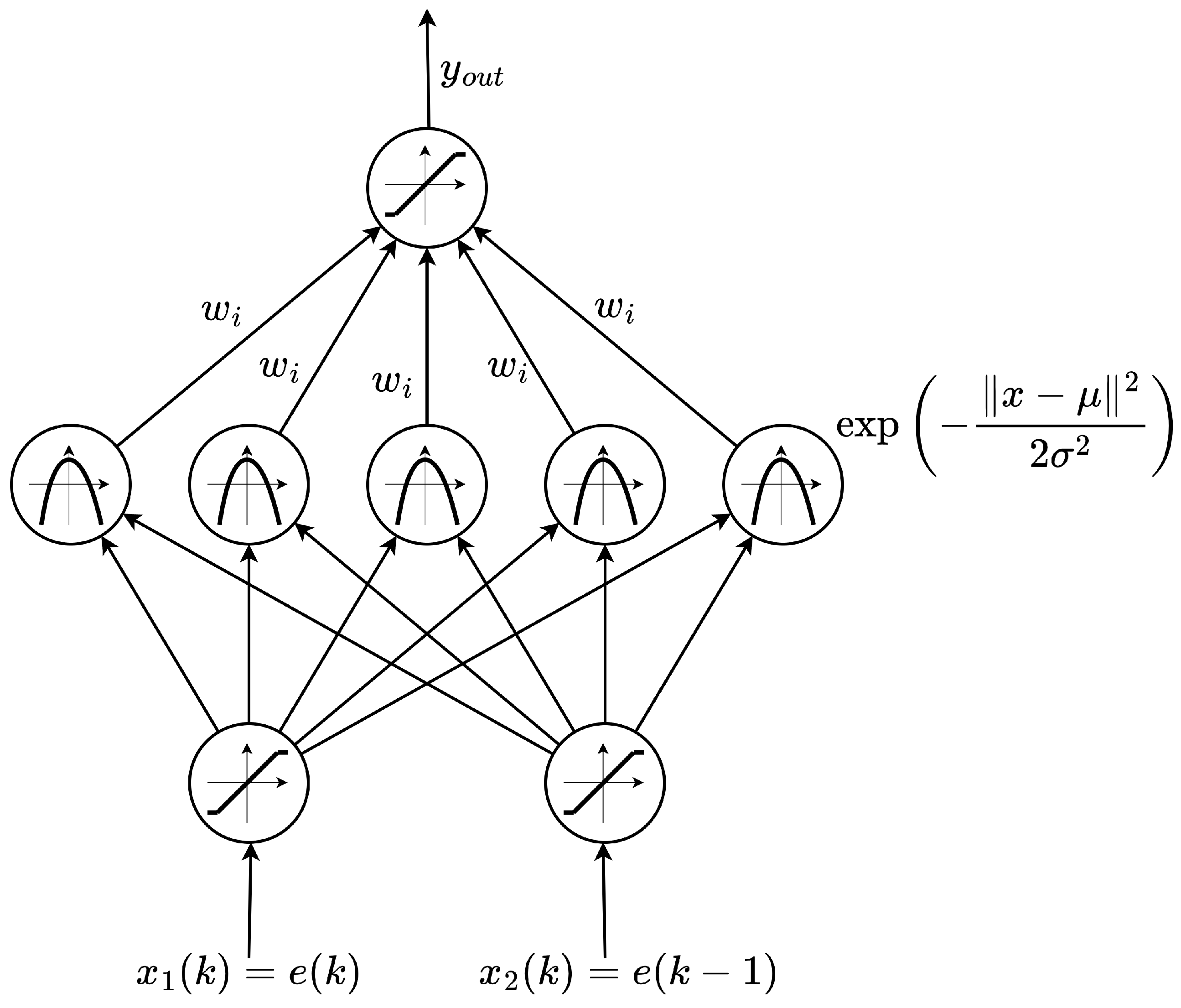
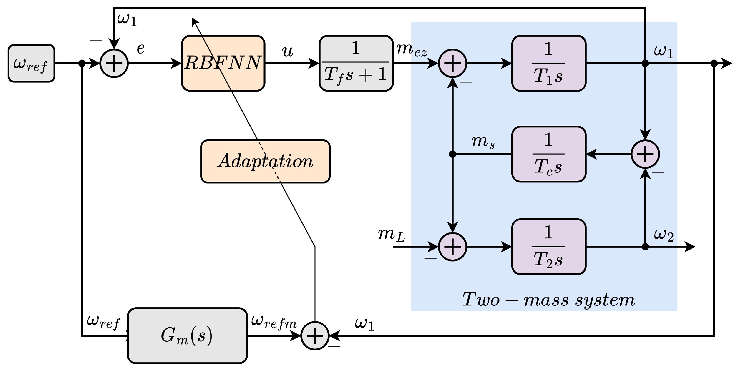
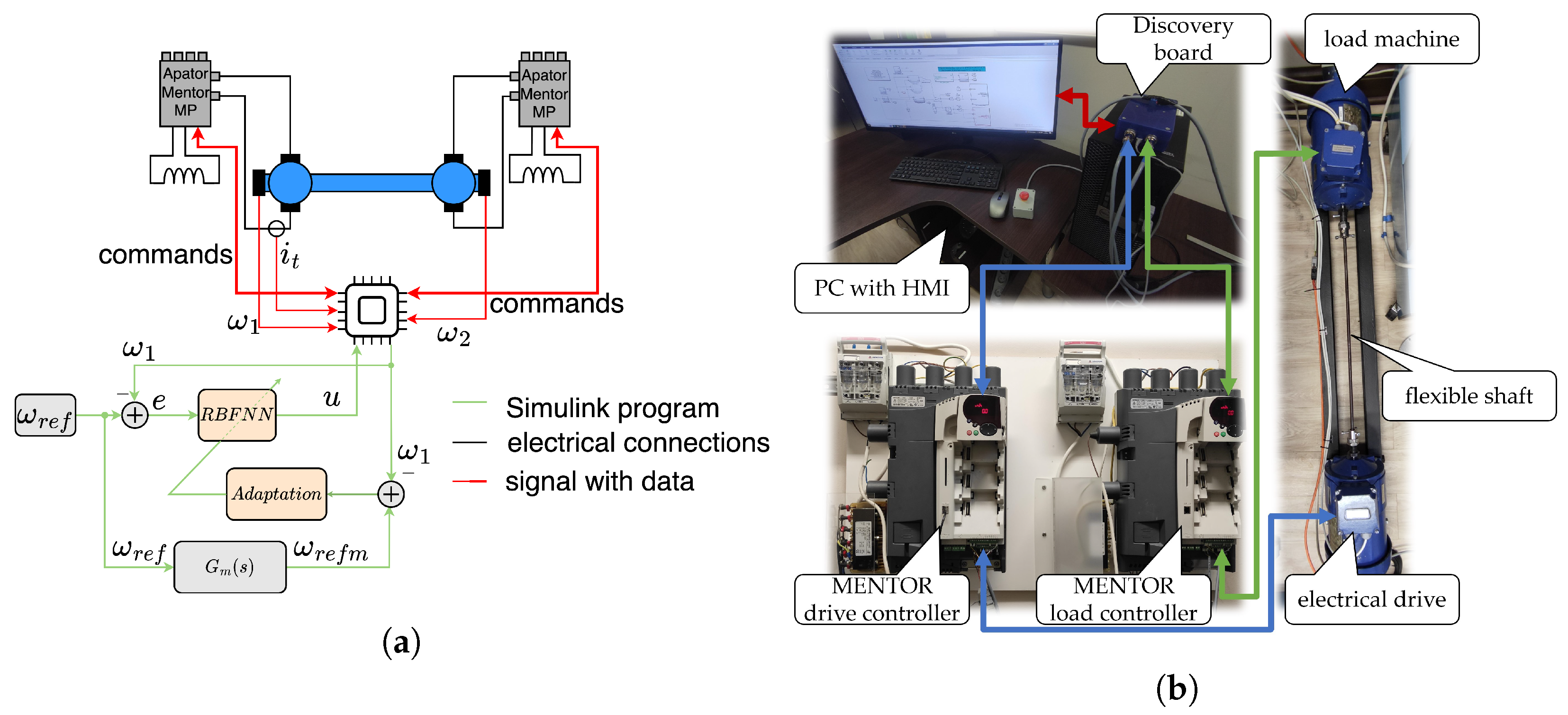
2. Description of the Plant and the Controller

The analyzed cascade control structure (Figure 2) consists of two loops: the outer loop with the speed controller (RBFNN), and the inner loop, which is tied to the power converter; the last part of the system is the plant—the two-mass drive.
The current loop (the inner loop) is responsible for creating an electromagnetic torque and can be described in the following manner:
G i ( s ) = 1 T f s + 1
where T f is the total time of the current control loop and the power electronics operation, s is the Laplace operator.
It was assumed that there was no delay in this part of the drive. Hence, the time constant was set to zero, and the final equation can be rewritten as:
G i ( s ) = 1 .
The plant is based on two electrical machines coupled by a long shaft. Such a system is often referred to as the two-mass system [46,47]. Nonlinear phenomena such as friction and backlash were omitted in the equations [48,49,50,51,52]:
ω 1 s = m e m s T 1
ω 2 s = m s m L T 2
m s s = ω 1 ω 2 T c
where ω 1 and ω 2 are the speed of the motor and the load, respectively, m e and m s are the electromagnetic and torsional torque, m L is the disturbance (the load torque). T 1 , T 2 , and T c are the time constants which correspond to the motor, the load, and the shaft. The parameters of the control system were adjusted to the laboratory setup so that the time constants correspond. All variables were assumed to be observable and available to the control algorithm.
RBF neural networks are a special case of feedforward neural networks [53]. Their distinctive feature is that they always have one hidden layer whose neurons have radial activation functions. The most commonly used radial basis function can be described using the following formula [54]:
h i = exp x μ i 2 2 σ i 2
where h i —the output of the i-th hidden layer neuron, x—the input vector, μ j —the center vector of the j-th neuron, | | · | | —euclidean distance, σ j —the width of the activation function. The output of the RBF neural network can then be calculated as:
y o u t = i = 0 n w i h i
with w i being the i-th weight. The online weight update approach was chosen to ensure adaptability and robustness to changes in parameters. The gradient descent algorithm was selected to update weights of the neural network. The weights are updated as in the equation presented below:
w i ( k + 1 ) = w i ( k ) + Δ w i ( k ) .
With the cost function described as:
E ( k ) = 1 2 ω r e f m ( k ) ω 1 ( k ) 2
where ω r e f m ( k ) —the desired value of the angular speed from the reference model in the k-th iteration [12]. The correction value for the i-th weight can be calculated as:
Δ w i ( k ) = η E ( k ) w i ( k ) = η ω r e f m ( k ) ω 1 ( k ) h i ( k )
where η —learning rate. To adjust the structure of the network, the parameters of the radial activation function are also subject to adaptation. The new values of center and widths are calculated as follows:
μ i ( k + 1 ) = μ i ( k ) + Δ μ i ( k )
σ i ( k + 1 ) = σ i ( k ) + Δ σ i ( k ) .
The following equations describing the adaptation for centers μ i and widths σ i were applied:
Δ μ i ( k ) = γ e m ( k ) h i ( k ) w i ( k ) · x μ i σ i 2
Δ σ i ( k ) = γ e m ( k ) h i ( k ) w i ( k ) · x ( k ) μ i ( k ) 2 σ i 3
where γ is learning rate associated with the parameters of the radial basis functions.

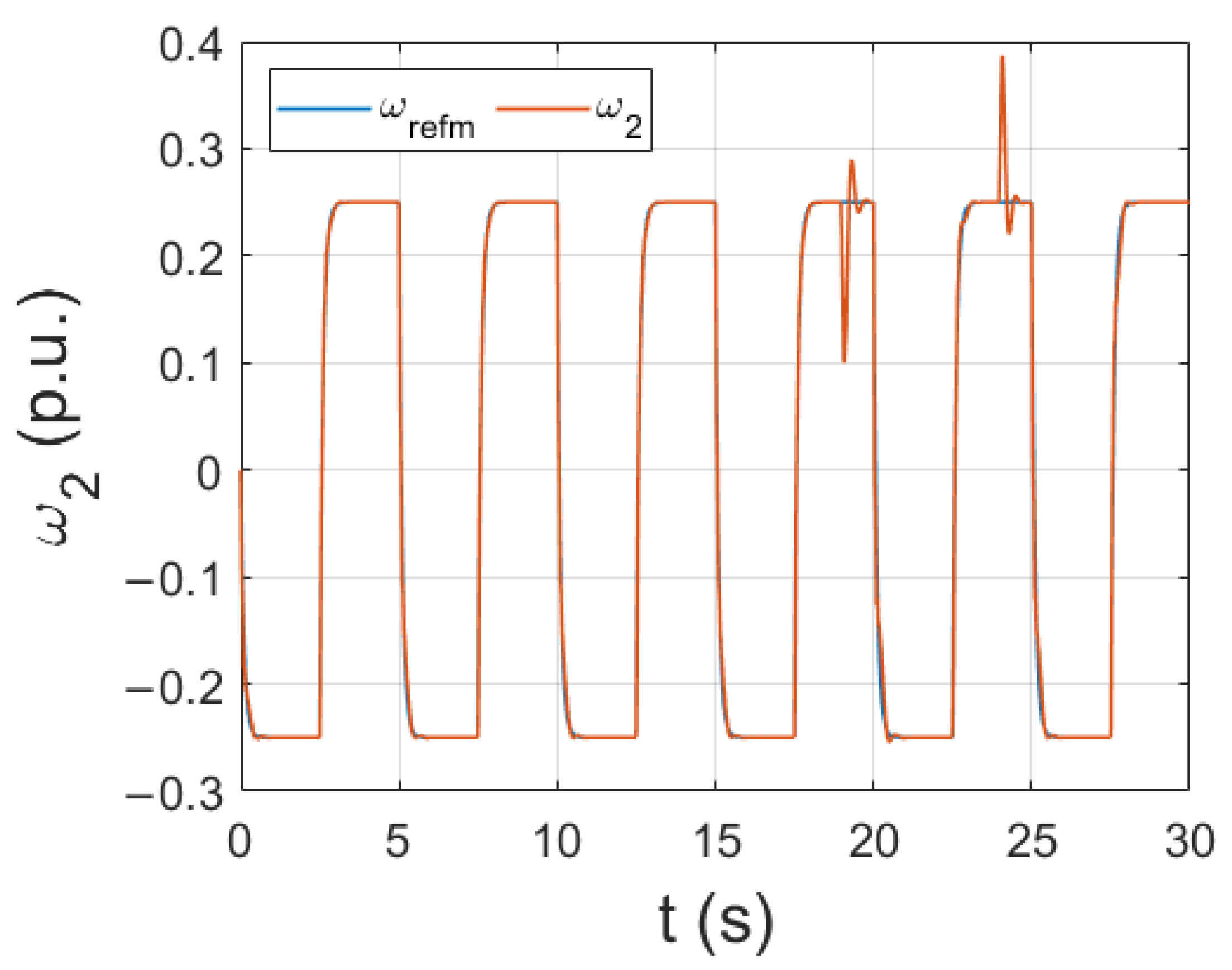
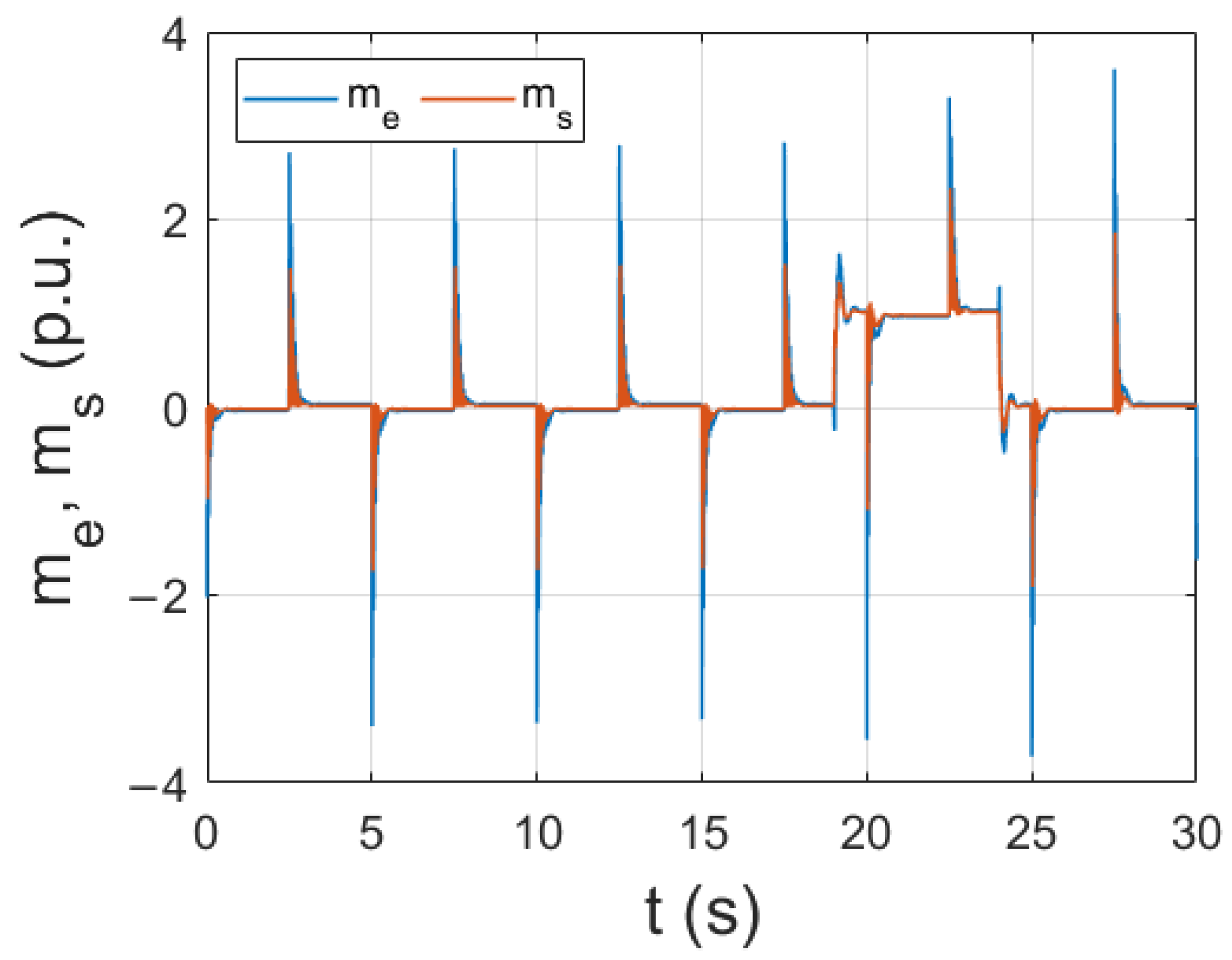
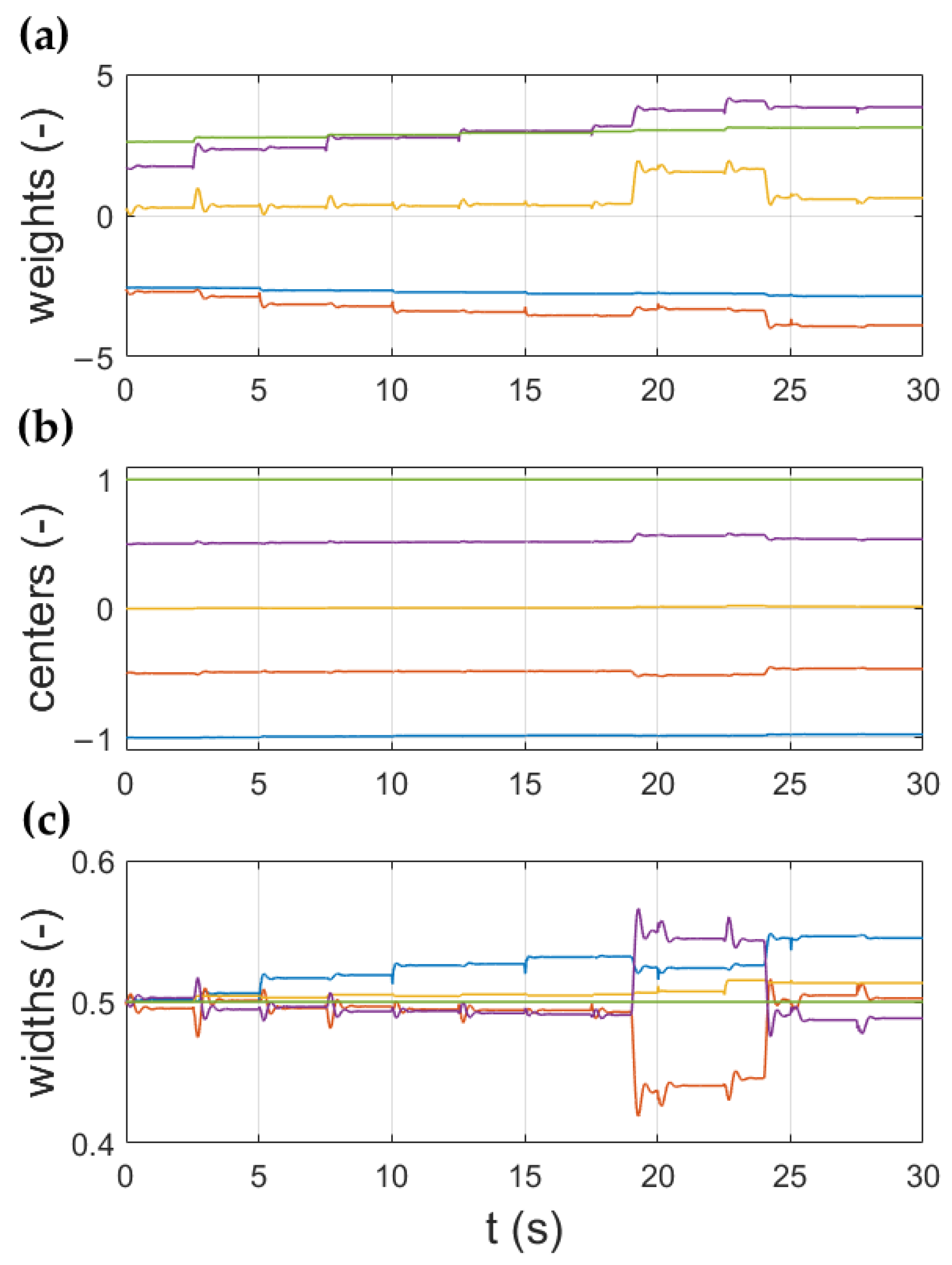
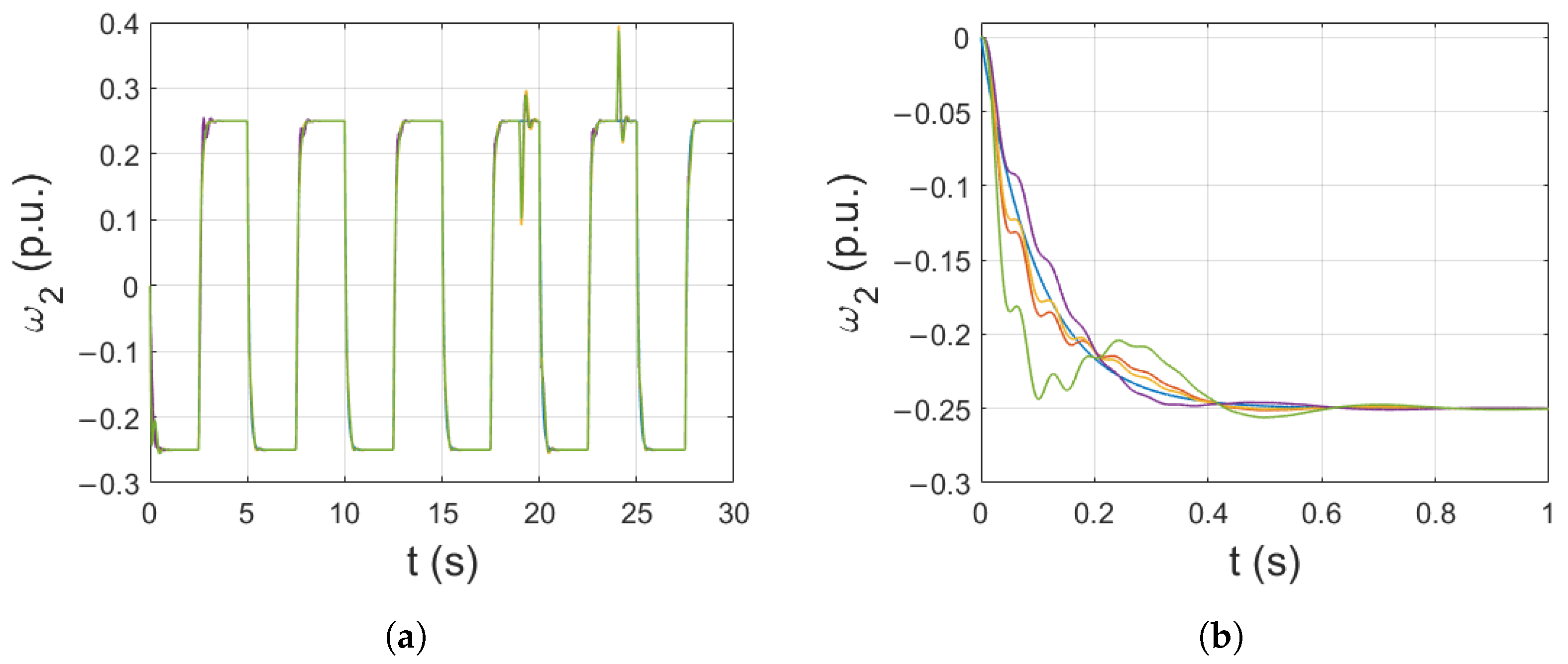
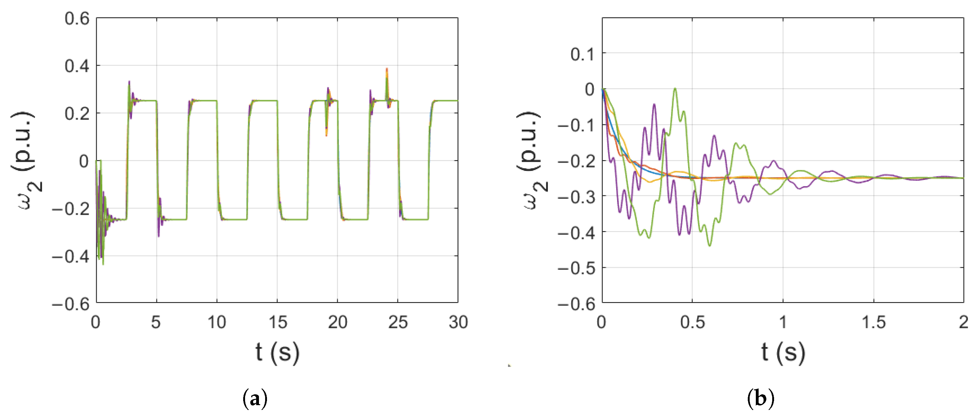
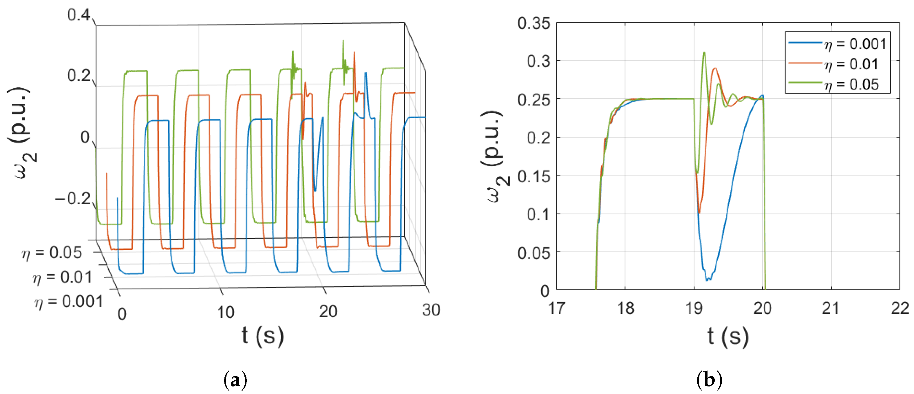
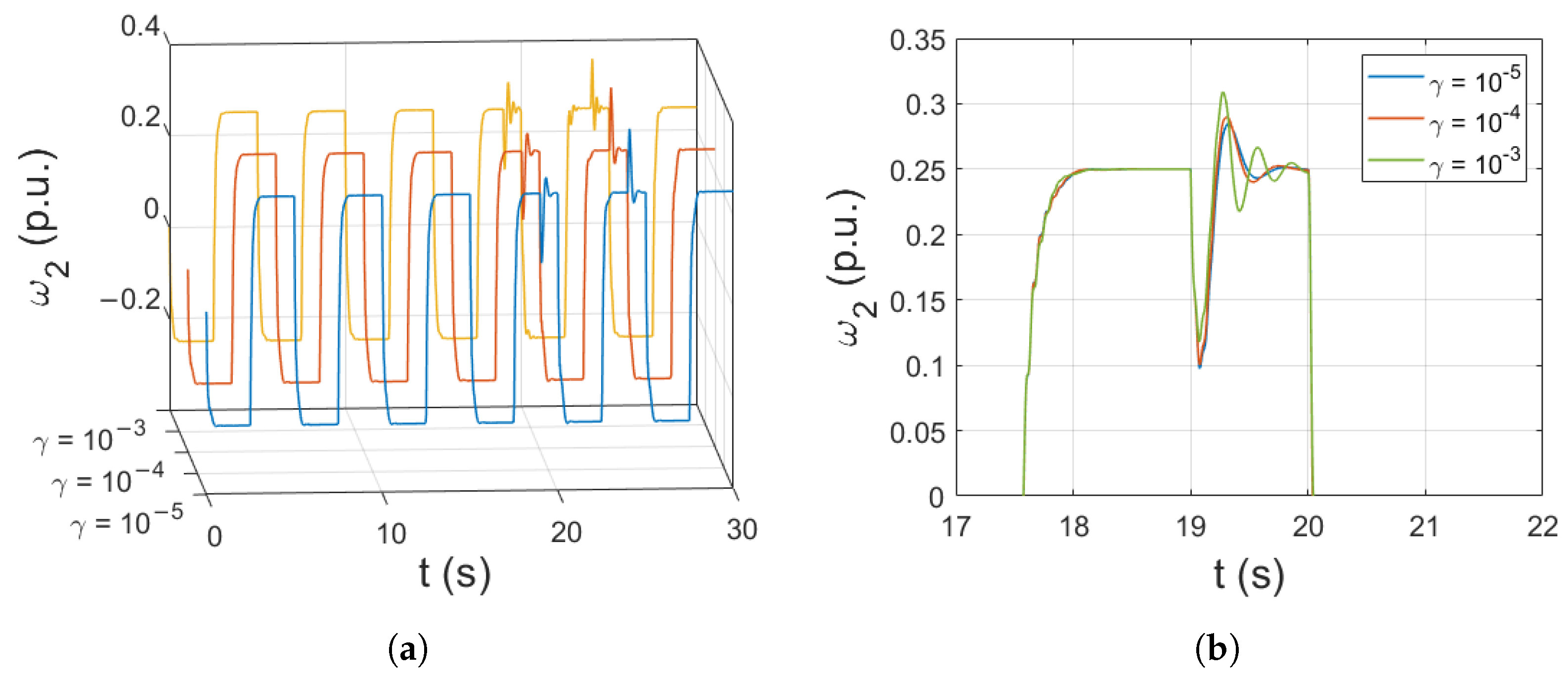
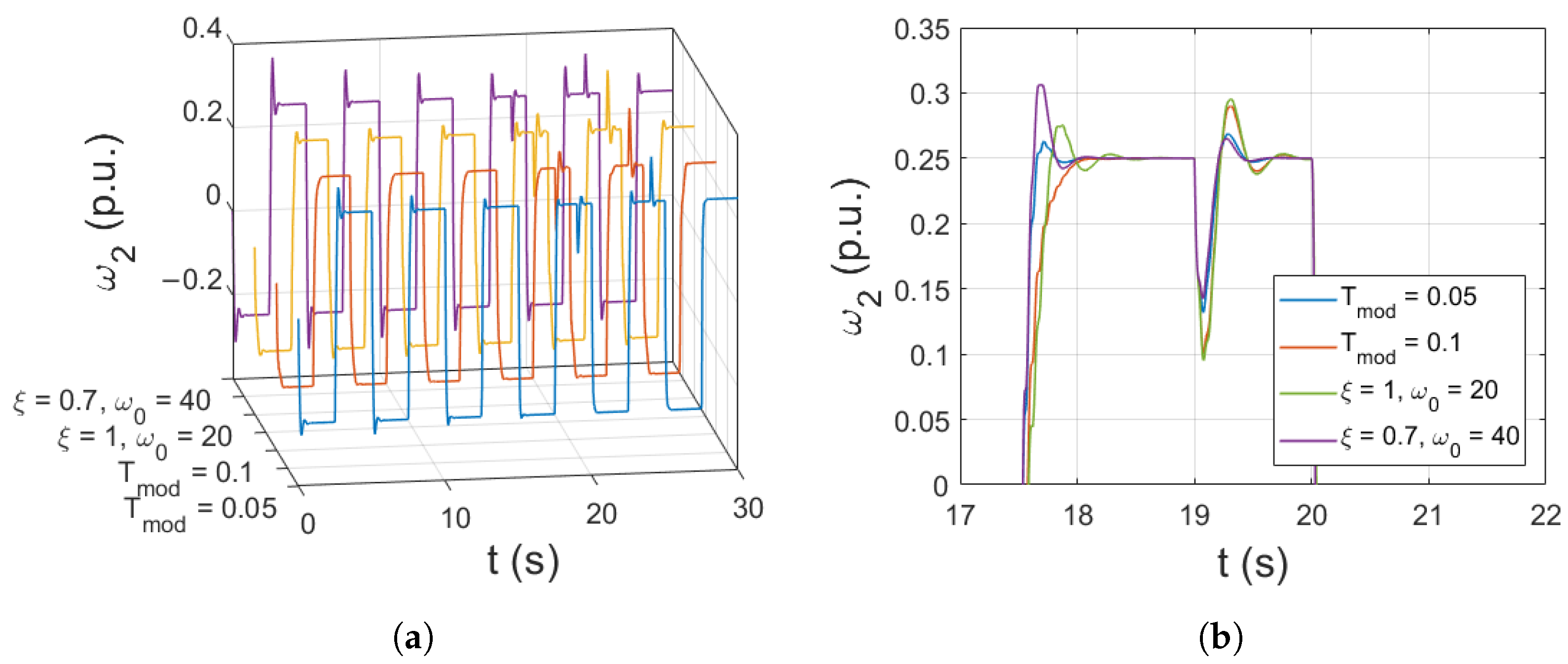
3. Simulation Results

The numerical tests were conducted to determine the behavior of the proposed control structure. The calculations were carried out with a calculation step of 0.1 ms. The initial weight values were randomly assigned in the range of (0, 0.1). The adaptation of widths started with the value of σ i = 0.5 . The initial center matrix— μ —was established empirically (the arrangement is symmetrical). There are five radial neurons in the hidden layer of the RBF neural network. The input vector of the network consists of two signals: the value of the speed error in the current and the previous iteration.
The behavior of the system (the rotational speed of the load and the electromagnetic and torsional torques) that works under nominal conditions is presented in Figure 3 and Figure 4. The speed of the load machine follows the reference value ω r e f m with high precision. The response to the load disturbance is dynamic and does not generate significant oscillations. The control system operates in a stable manner.
To additionally test the adaptation efficiency of the proposed control scheme, a change in drive parameters was introduced. In applications such as paper winding machines, the inertia of the load machine increases over time. Therefore, the operation of the drive with an increased time constant T 2 was verified. The simulation results obtained for this case are presented in Figure 5. The adaptation of all parameters can be seen. With each reversion, the overshoot is reduced, resulting in a smoother transition between the steady states. The changes in the adapted parameters: weights, centers, and widths are presented in Figure 6a, b and c, respectively. The most significant changes can be observed in the transients of weights and widths of the radial functions. The presented centers are evenly distributed, fulfilling the role of global mapping of the whole data space.
Changes in all parameters of the network were also individually inspected. The impact of the initial values of weights, centers, widths, and also values of learning rates ( η and γ ) is shown. The load machine speed transients for different sets of initial weights are presented in Figure 7. After the start of the drive, for most of the sets tested, significant oscillations can be observed. Later, they are dampened because of the adaptation process. Nevertheless, the oscillations of the load speed must be minimized. Therefore, optimization of these parameters is highly recommended.
The effect of the change in the initial widths of the radial functions is presented in Figure 8. The widths were selected at random in the range of (0.25, 0.75). No major changes in the load speed transients can be observed. After a few reversions, the runs are almost identical.
The load speeds with different values of center of the radial functions can be seen in Figure 9. These initial parameters also do not introduce any changes that affect the operation of the drive for more than a few first reversions. The learning algorithm mitigates the inadequacy in center selection in the later stages of the simulation.
The impact of learning rates associated with weights ( η ), center and widths ( γ ) is presented in Figure 10 and Figure 11, respectively. The lower value of η results in slower adaptation, which results in a delayed response to load switching. On the other hand, higher values cause a larger overshoot and introduce oscillations. It can be stated that this parameter should be chosen carefully or optimized.
The learning coefficient responsible for adjusting the adaptation process of center and widths is not as impactful due to its lower value. However, higher values still cause the occurrence of oscillations.
The final test was conducted to verify the effect of the input signal filter on drive behavior. The comparison is presented in Figure 12. Each of the models was tested for two different sets of values.
The first filter is described as a one-degree-of-freedom transfer function:
G m ( s ) = 1 T m o d s + 1 ,
while the other has two degrees of freedom and takes the following form:
G m ( s ) = ω 0 2 s 2 + 2 s ξ ω 0 + ω 0 2 ,
where T m o d —the filter time constant, ξ —the damping coefficient, ω 0 —the resonant frequency of the system.
For the same initial values of weights and learning rate, the settling time remains similar. Overshoot can be eliminated by lowering the dynamics of the reference signal (increasing T m o d ). As expected, with more degrees of freedom, the reference signal can be shaped with higher precision. It is important to note that also the learning coefficient η must be adjusted to meet the demand for the system’s speed response. Otherwise, overshoots or oscillations might appear.

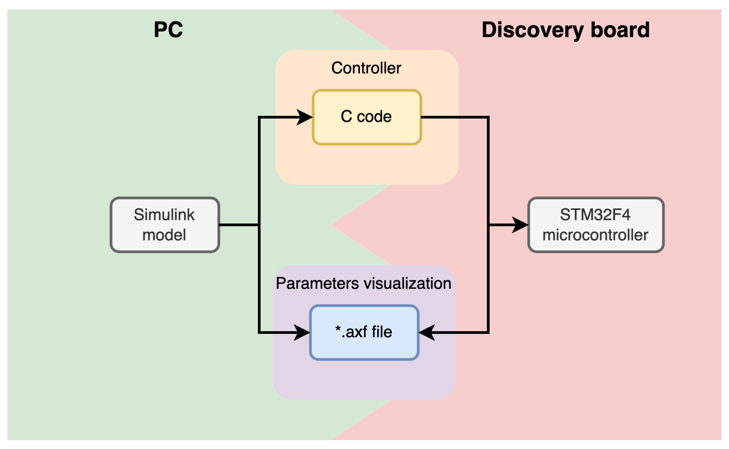
4. Low-Cost Implementation of the Control Algorithm

The main contribution of this research was the implementation of the designed controller on a low-cost microcontroller board. Power electronic devices were obtained through the application of industrial MENTOR converters. The original software settings of the industrial machines were reconfigured to allow communication with the external speed controller. The required feedback signals were acquired by external sensors; the incremental encoders were attached to the motor and load machine shafts, and the LEM current sensor was attached to the drive powerline. The output was routed directly to the Discovery board with the STM32F4 microprocessor, and the 36,000 ppr incremental encoders were also connected to the MENTOR controllers (Figure 13).
The framework between the drives and the microcontroller board was obtained using STMStudio software. The controller structure was designed in Simulink and the C code was generated. The Discovery board was flashed with the obtained firmware, and the variable list file was developed. Based of the file, a human–machine interface (HMI) application was created. The HMI allows the user to observe drive state variables and plot speed transients. The application also provides basic control over the plant. The fully functional low-cost Hardware-in-the-Loop (HIL) system was obtained (Figure 14). The connection between the PC and the Discovery board was obtained with the USB cable and the ST-link embedded in-circuit programmer. Not only did the established connection provide the possibility to flash the new firmware to the board, but also allowed real-time monitoring of the system variables.
The Discovery board with the STM32F407 microprocessor was chosen because of the necessity to use two digital-to-analog converters (DAC). Moreover, the performance and variety of the available connectivity modules on the chosen board were compared to the laboratory dSpace DS1103 hardware. Although the dSpace incorporates an FPGA module, its price exceeds the cost of a Discovery board multiple times. Several chosen parameters are compared in Table 1.
The low-cost board can be considered less powerful with the synthetic performance of only 210 DMIPS (compared to about 2300 DMIPS obtained by dSpace processor); however, it offers a greater number of general-purpose input/output ports and communication modules. Compared with the dSpace module, the Discovery board incorporates more timers that are multipurpose elements. In the designed structure, the timers were used for encoder data acquisition. The pulses were counted and after the determined period, they were used to calculate the speed of the drive and the load machine. Both devices include processors, which can perform simple data operations in real-time. The FPGA module is not included in the Discovery board, making parallel computation of the RBFNN structure impossible. However, the proposed model was simple enough that the response of the microprocessor was sufficient for the controlled plant. As the speed controllers can be applied in mobile machinery, energy efficiency was also considered. The suggested STM microcontroller average current consumption is declared at the level of 40 mA [55], while dSpace requires up to 750 mA [56].
The software part of the designed HIL was based on the simulation model. The output of the RBFNN speed controller was sent to the torque controller. The signal was then normalized and converted to an analog signal with a corresponding voltage output level. The digital output of the microcontroller was used to switch the relays of the MENTOR power electronics. They were used to define the direction of drive rotation, global enable, and start of operation.
To configure the MENTOR drives, the CTSoft application was used (Figure 15). It comprises a wide range of graphical interfaces to change the parameters of the drive. In order to allow operation in the torque mode, some changes in the default configuration were essential. Then, the signal from Discovery’s analog output can be sent to the MENTOR drive. Safety features are built-in; tripping occurs when overspeed/overcurrent, overheating of the motor, or incorrect configuration (for instance, a wrong number of pulses per revolution of the installed encoder) is detected. The final configuration can be sent to the drive and saved in its memory for later use.
The STMStudio software was used for data acquisition. Variables from the generated code can be imported to the project as read-only to show the desired variables (e.g., speed of the load) or as a read/write—to change the value of the reference speed or to drive the corresponding relay. Data are then plotted in real-time. In the end, a *.txt file is generated. The file can later be imported to Matlab to plot the acquired transient.
Figure 16 presents the transient of the rotational speed of the load machine obtained from the experimental verification of the proposed control structure. The speed follows the reference trajectory with high precision. The response is dynamic and there is no overshoot.
The trapezoidal reference signal is often used in industrial applications to ensure the safety of operation. Because of that, it is the default setting for the MENTOR power electronics controller. Therefore, it was decided that the test would be conducted under these conditions. The verification of the control structure with a more demanding reference signal, such as a square wave, will be considered to be a relevant point for future research.
The adaptation process can be observed through the transients of weights of the neural network. The changes are presented in Figure 17. The weights started with values randomly selected from a range of ( 0 , 0.1 ] and managed to significantly increase their value over the period of the experiment. Greater growth (compared to the numerical tests) is expected because of the speed being expressed in rpms (unlike the numerical tests, where the angular speed is expressed in per-unit notation).
The drive was also tested for different values of the speed set point. The results are shown in Figure 18. In all the cases, the proposed control scheme manages to follow the reference signal. A great finding is that the structure operates correctly even for lower speed values. Usually, because of less frequent rotations, the fan placed on the shaft of the motor does not manage to cool the machine efficiently enough. The increase in armature winding temperature causes an increase in its resistance, thus changing the parameters of the plant. The control structure manages to withstand those changes and continues to precisely follow the reference signal.

5. Conclusions

In this study, an adaptive RBFNN speed controller was implemented on an STM32F407 microcontroller. The use of the ARM device enables the overall cost of the electrical drive to be reduced without any significant loss in control quality. The training algorithm calculates new values for weights, centers, and widths (of the activation functions) of the neural network. The performance of the drive with increased inertia was also improved—the adaptation process adjusts the controller to the current state of the drive. The additional benefit is that no additional information about the load machine is needed to be supplied to the control structure—the drive operates with just the information about the speed of the motor and the armature current. Compared to other advanced control schemes (which usually require the use of multiple signals), it also provides an improvement in costs—no additional sensors need to be added to the structure. Furthermore, for the same reason, the reliability of the proposed control structure is greater. This is because there are fewer devices that could potentially be damaged or cause faulty operation.

Author Contributions

Conceptualization, M.K.; methodology, M.K., R.S., M.M. and M.Z.; software, R.S., M.M. and M.Z.; validation, M.K., R.S., M.M. and M.Z.; formal analysis, M.K.; investigation, M.K., R.S., M.M. and M.Z.; resources, M.K.; data curation, R.S., M.M. and M.Z.; writing—original draft preparation, M.K., R.S., M.M. and M.Z.; writing—review and editing, M.K., R.S., M.M. and M.Z.; visualization, R.S. and M.Z.; supervision, M.K.; project administration, M.K.; funding acquisition, M.K. All authors have read and agreed to the published version of the manuscript.

Funding

This research received no external funding.

Data Availability Statement

Not applicable.

Conflicts of Interest

The authors declare no conflict of interest.

Abbreviations

The following abbreviations and symbols are used in this manuscript:
DACDigital-to-Analog Converter
DSPDigital Signal Processor
eerror signal
FPGAField Programmable Gate Array
GPIOGeneral-Purpose Input/Output
HMIHuman–Machine Interface
HILHardware-in-the-Loop
m e electromagnetic torque
m L load torque
m s torsional torque
pprpulses per revolution
p.u.per unit
PWMPulse Width Modulation
RBFRadial Basis Function
RBFNNRadial Basis Function Neural Network
rpmrevolutions per minute
T 1 time constant of the motor machine
T 2 time constant of the load machine
T c time constant of the shaft
T m o d reference speed time constant
wweights of a neural network
γ learning rate of center and widths of neurons
ξ damping coefficient
η learning rate of weights of the neural network
μ center of the neuron
σ width of the neuron
ω 0 resonant frequency of the system
ω 1 speed of the motor
ω 2 speed of the load
ω r e f m model reference speed

References

  1. Liu, Z.-H.; Nie, J.; Wei, H.-L.; Chen, L.; Li, X.-H.; Lv, M.-Y. Switched PI Control Based MRAS for Sensorless Control of PMSM Drives Using Fuzzy-Logic-Controller. IEEE Open J. Power Electron. 2022, 3, 368–381. [Google Scholar] [CrossRef]
  2. Hussain, H.A. Tuning and Performance Evaluation of 2DOF PI Current Controllers for PMSM Drives. IEEE Trans. Transp. Electrif. 2021, 7, 1401–1414. [Google Scholar] [CrossRef]
  3. Stojic, D.; Tarczewski, T.; Niewiara, L.J.; Grzesiak, L.M. Improved Fixed-Frequency SOGI Based Single-Phase PLL. Energies 2022, 15, 7297. [Google Scholar] [CrossRef]
  4. Salgado-Plasencia, E.; Carrillo-Serrano, R.V.; Toledano-Ayala, M. Development of a DSP Microcontroller-Based Fuzzy Logic Controller for Heliostat Orientation Control. Appl. Sci. 2020, 10, 1598. [Google Scholar] [CrossRef] [Green Version]
  5. Liu, T.-H.; Ahmad, S.; Mubarok, M.S.; Chen, J.-Y. Simulation and Implementation of Predictive Speed Controller and Position Observer for Sensorless Synchronous Reluctance Motors. Energies 2020, 13, 2712. [Google Scholar] [CrossRef]
  6. Ortega-García, L.E.; Rodriguez-Sotelo, D.; Nuñez-Perez, J.C.; Sandoval-Ibarra, Y.; Perez-Pinal, F.J. DSP-HIL Comparison between IM Drive Control Strategies. Electronics 2021, 10, 921. [Google Scholar] [CrossRef]
  7. Mossa, M.A.; Echeikh, H.; Iqbal, A.; Do, T.D.; Al-Sumaiti, A.S. A Novel Sensorless Control for Multiphase Induction Motor Drives Based on Singularly Perturbed Sliding Mode Observer-Experimental Validation. Appl. Sci. 2020, 10, 2776. [Google Scholar] [CrossRef] [Green Version]
  8. Luo, G.; Zhang, R.; Chen, Z.; Tu, W.; Zhang, S.; Kennel, R. A Novel Nonlinear Modeling Method for Permanent-Magnet Synchronous Motors. IEEE Trans. Ind. Electron. 2016, 63, 6490–6498. [Google Scholar] [CrossRef]
  9. Mishra, P.; Banerjee, A.; Ghosh, M. FPGA-Based Real-Time Implementation of Quadral-Duty Digital-PWM-Controlled Permanent Magnet BLDC Drive. IEEE/ASME Trans. Mechatron. 2020, 25, 1456–1467. [Google Scholar] [CrossRef]
  10. Zhang, D.; Li, H. A Stochastic-Based FPGA Controller for an Induction Motor Drive with Integrated Neural Network Algorithms. IEEE Trans. Ind. Electron. 2008, 55, 551–561. [Google Scholar] [CrossRef]
  11. Wongkhead, S.; Tunyasrirut, S.; Permpoonsinsup, W.; Puangdownreong, D. State Space Model for BLDC Motor Based on Digital Sigal Processors TMS320F28335 for Speed Control by Using Proportional Integral Controller. In Proceedings of the 2019 7th International Electrical Engineering Congress (iEECON), Hua Hin, Thailand, 6–8 March 2019; pp. 1–4. [Google Scholar] [CrossRef]
  12. Derugo, P.; Zychlewicz, M. Reproduction of the control plane as a method of selection of settings for an adaptive fuzzy controller with Petri layer. Arch. Electr. Eng. 2020, 69, 609–624. [Google Scholar] [CrossRef]
  13. Frieske, B.; Stieler, S. The “Semiconductor Crisis” as a Result of the COVID-19 Pandemic and Impacts on the Automotive Industry and Its Supply Chains. World Electr. Veh. J. 2022, 13, 189. [Google Scholar] [CrossRef]
  14. Gopinath, M.; Yuvaraja, T.; Jeykumar, S. Implementation of Four Quadrant Operation of BLDC Motor Using Model Predictive Controller. Mater. Proc. 2018, 15, 1666–1672. [Google Scholar] [CrossRef]
  15. Xu, H.; Hinostroza, M.A.; Guedes Soares, C. Modified Vector Field Path-Following Control System for an underactuated Autonomous surface ship model in the presence of static obstacles. J. Mar. Sci. Eng. 2021, 9, 652. [Google Scholar] [CrossRef]
  16. McCarthy, D.; McMorrow, D.; O’Dowd, N.P.; McCarthy, C.T.; Hinchy, E.P. A Model-Based Approach to Automated Validation and Generation of PLC Code for Manufacturing Equipment in Regulated Environments. Appl. Sci. 2022, 12, 7506. [Google Scholar] [CrossRef]
  17. Mihalič, F.; Truntič, M.; Hren, A. Hardware-in-the-Loop Simulations: A Historical Overview of Engineering Challenges. Electronics 2022, 11, 2462. [Google Scholar] [CrossRef]
  18. Ivanov, E.; Karsakov, A. Visual programming language for data visualization based on visual grammar. Procedia Comput. Sci. 2021, 193, 402–406. [Google Scholar] [CrossRef]
  19. Michael, C.A.; Safacas, A.N. Dynamic and Vibration Analysis of a Multimotor DC Drive System with Elastic Shafts Driving a Tissue Paper Machine. IEEE Trans. Ind. Electron. 2007, 54, 2033–2046. [Google Scholar] [CrossRef]
  20. Michael, C.; Safacas, A. Behavior of a drive system consisting of two DC motors with elastic shafts driving the Yankee drying cylinder of a tissue paper machine. In Proceedings of the 4th International Power Electronics and Motion Control Conference, Xi’an, China, 14–16 August 2004; Volume 3, pp. 1460–1465. [Google Scholar]
  21. Gaidi, A.; Lehouche, H.; Belkacemi, S.; Tahraoui, S.; Loucif, M.; Guenounou, O. Adaptive Backstepping control of wind turbine two mass model. In Proceedings of the 2017 6th International Conference on Systems and Control (ICSC), Batna, Algeria, 7–9 May 2017; pp. 168–172. [Google Scholar] [CrossRef]
  22. Li, X.; Zhu, Y.; Yang, K.-m. Self-adaptive composite control for flexible joint robot based on RBF neural network. In Proceedings of the 2010 IEEE International Conference on Intelligent Computing and Intelligent Systems, Xiamen, China, 29–31 October 2010; pp. 837–840. [Google Scholar] [CrossRef]
  23. Xin, X.; Liu, Y.; Wu, J. Global stabilization control for a two-link underactuated robot with a flexible elbow joint. In Proceedings of the 32nd Chinese Control Conference, Xi’an, China, 26–28 July 2013; pp. 1520–1525. [Google Scholar]
  24. Goubej, M. Fundamental performance limitations in PID controlled elastic two-mass systems. In Proceedings of the 2016 IEEE International Conference on Advanced Intelligent Mechatronics, Banff, AB, Canada, 12–15 July 2016; pp. 828–833. [Google Scholar] [CrossRef]
  25. Wang, C.; Yang, M.; Zheng, W.; Long, J.; Xu, D. Vibration Suppression With Shaft Torque Limitation Using Explicit MPC-PI Switching Control in Elastic Drive Systems. IEEE Trans. Ind. Electron. 2015, 62, 6855–6867. [Google Scholar] [CrossRef]
  26. Szabat, K.; Pajchrowski, T.; Tarczewski, T. Modern Electrical Drives: Trends, Problems, and Challenges. Energies 2022, 15, 160. [Google Scholar] [CrossRef]
  27. Derugo, P.; Szabat, K.; Pajchrowski, T.; Zawirski, K. Fuzzy Adaptive Type II Controller for Two-Mass System. Energies 2022, 15, 419. [Google Scholar] [CrossRef]
  28. Szabat, K.; Orlowska-Kowalska, T. Vibration Suppression in a Two-Mass Drive System Using PI Speed Controller and Additional Feedbacks—Comparative Study. IEEE Trans. Ind. Electron. 2007, 54, 1193–1206. [Google Scholar] [CrossRef]
  29. Zhang, G.; Furusho, J. Speed control of two-inertia system by PI/PID Control. IEEE Trans. Ind. Electron. 2000, 47, 603–609. [Google Scholar] [CrossRef]
  30. Wongkhead, S. State Space Model for Speed Control BLDC Motor Tuning by Combination of PI—Artificial Neural Network Controller. In Proceedings of the 2021 18th International Conference on Electrical Engineering/Electronics, Computer, Telecommunications and Information Technology (ECTI-CON), Chiang Mai, Thailand, 19–22 May 2021; pp. 874–877. [Google Scholar] [CrossRef]
  31. Dróżdż, K. Estimation of the mechanical state variables of the two-mass system using fuzzy adaptive Kalman filter—Experimental study. In Proceedings of the 2015 IEEE 2nd International Conference on Cybernetics (CYBCONF), Gdynia, Poland, 24–26 June 2015; pp. 455–459. [Google Scholar] [CrossRef]
  32. Nikolov, N.; Alexandrova, M. Adaptive state controller with suspension of the recurrent estimation process. In Proceedings of the 2021 International Conference Automatics and Informatics (ICAI), Varna, Bulgaria, 30 September–2 October 2021; pp. 1–4. [Google Scholar] [CrossRef]
  33. Malarczyk, M.; Zychlewicz, M.; Stanislawski, R.; Kaminski, M. Speed Control Based on State Vector Applied for Electrical Drive with Elastic Connection. Automation 2022, 3, 337–363. [Google Scholar] [CrossRef]
  34. Szczepanski, R.; Tarczewski, T.; Grzesiak, L.M. Application of optimization algorithms to adaptive motion control for repetitive process. ISA Trans. 2021, 115, 192–205. [Google Scholar] [CrossRef]
  35. Gil, P.; Oliveira, T.; Cardoso, A.; Palma, L. Adaptive State-Space Neuro Fuzzy Control. In Proceedings of the 2018 15th International Conference on Electrical Engineering/Electronics, Computer, Telecommunications and Information Technology (ECTI-CON), Chiang Rai, Thailand, 18–21 July 2018; pp. 45–48. [Google Scholar] [CrossRef]
  36. Fei, J.; Chen, Y.; Liu, L.; Fang, Y. Fuzzy Multiple Hidden Layer Recurrent Neural Control of Nonlinear System Using Terminal Sliding-Mode Controller. IEEE Trans. Cybern. 2022, 52, 9519–9534. [Google Scholar] [CrossRef]
  37. Skowron, M.; Orlowska-Kowalska, T.; Kowalski, C.T. Detection of Permanent Magnet Damage of PMSM Drive Based on Direct Analysis of the Stator Phase Currents Using Convolutional Neural Network. IEEE Trans. Ind. Electron. 2022, 69, 13665–13675. [Google Scholar] [CrossRef]
  38. Chu, Y.; Fei, J.; Hou, S. Adaptive Global Sliding-Mode Control for Dynamic Systems Using Double Hidden Layer Recurrent Neural Network Structure. IEEE Trans. Neural Netw. Learn. Syst. 2020, 31, 1297–1309. [Google Scholar] [CrossRef]
  39. Duan, J.; Jiang, Y.; Zhao, J.; Tang, Y. Design of wavelet neural network controller based on genetic algorithm. In Proceedings of the 2017 IEEE 3rd Information Technology and Mechatronics Engineering Conference (ITOEC), Chongqing, China, 3–5 October 2017; pp. 1109–1112. [Google Scholar] [CrossRef]
  40. El-Sousy, F.F.M.; Abuhasel, K.A. Self-organizing recurrent fuzzy wavelet neural network-based mixed H2/H∞ adaptive tracking control for uncertain two-axis motion control system. In Proceedings of the 2015 IEEE Industry Applications Society Annual Meeting, Addison, TX, USA, 18–22 October 2015; pp. 1–14. [Google Scholar] [CrossRef]
  41. Zawarczyński, Ł.; Stefański, T. Damping of torsional vibrations in electric drive with AC motor. In Proceedings of the 2018 International Interdisciplinary PhD Workshop (IIPhDW), Swinoujscie, Poland, 9–12 May 2018; pp. 74–80. [Google Scholar] [CrossRef]
  42. Qu, C.; Hu, Y.; Guo, Z.; Han, F.; Wang, X. New Sliding Mode Control Based on Tracking Differentiator and RBF Neural Network. Electronics 2022, 11, 3135. [Google Scholar] [CrossRef]
  43. Nalepa, R.; Najdek, K.; Wróbel, K.; Szabat, K. Application of D-Decomposition Technique to Selection of Controller Parameters for a Two-Mass Drive System. Energies 2020, 13, 6614. [Google Scholar] [CrossRef]
  44. Chen, X.; Shen, W.; Dai, M.; Cao, Z.; Jin, J.; Kapoor, A. Robust Adaptive Sliding-Mode Observer Using RBF Neural Network for Lithium-Ion Battery State of Charge Estimation in Electric Vehicles. IEEE Trans. Veh. Technol. 2016, 65, 1936–1947. [Google Scholar] [CrossRef]
  45. Sun, Y.; Wang, X.; Wu, Q.; Sepheri, N. Calculation of Lyapunov exponents using Radial Basis Function networks for stability analysis of nonlinear control systems. In Proceedings of the 2011 American Control Conference, San Francisco, CA, USA, 29 June–1 July 2011; pp. 1978–1983. [Google Scholar] [CrossRef]
  46. Serkies, P.; Szabat, K. Predictive Control of the Two-Mass Drive with an Induction Motor for a Wide Speed Range. In Proceedings of the 2018 IEEE 18th International Power Electronics and Motion Control Conference (PEMC), Budapest, Hungary, 26–30 August 2018; pp. 750–755. [Google Scholar] [CrossRef]
  47. Lukichev, D.V.; Demidova, G.L.; Brock, S. Fuzzy adaptive PID control for two-mass servo-drive system with elasticity and friction. In Proceedings of the 2015 IEEE 2nd International Conference on Cybernetics (CYBCONF), Gdynia, Poland, 24–26 June 2015; pp. 443–448. [Google Scholar] [CrossRef]
  48. Szabat, K.; Tran-Van, T.; Kamiński, M. A Modified Fuzzy Luenberger Observer for a Two-Mass Drive System. IEEE Trans. Ind. Inform. 2015, 11, 531–539. [Google Scholar] [CrossRef]
  49. Kamiński, M.; Szabat, K. Adaptive Control Structure with Neural Data Processing Applied for Electrical Drive with Elastic Shaft. Energies 2021, 14, 3389. [Google Scholar] [CrossRef]
  50. Cychowski, M.; Delaney, K.; Szabat, K. Low-cost high-performance Predictive Control of drive systems with elastic coupling. In Proceedings of the 2008 13th International Power Electronics and Motion Control Conference, Poznan, Poland, 1–3 September 2008; pp. 2241–2247. [Google Scholar] [CrossRef]
  51. Nandana, J.; Anas, A.S. An efficient speed control method for two mass drive systems using ADALINE. In Proceedings of the 2015 International Conference on Smart Technologies and Management for Computing, Communication, Controls, Energy and Materials (ICSTM), Avadi, India, 6–8 May 2015; pp. 418–423. [Google Scholar] [CrossRef]
  52. Yakub, F.; Mori, Y. Intelligent control method for two-mass rotary positioning systems. In Proceedings of the SICE Annual Conference 2013, Nagoya, Japan, 14–17 September 2013; pp. 2524–2529. [Google Scholar]
  53. Lin, C.K. Radial basis function neural network-based adaptive critic control of induction motors. Appl. Soft Comput. 2011, 11, 3066–3074. [Google Scholar] [CrossRef]
  54. Brandstetter, P.; Kuchar, M. Sensorless control of variable speed induction motor drive using RBF neural network. J. Appl. Log. 2017, 24, 94–108. [Google Scholar] [CrossRef]
  55. Wu, H.; Chen, C.; Weng, K. An Energy-Efficient Strategy for Microcontrollers. Appl. Sci. 2021, 11, 2581. [Google Scholar] [CrossRef]
  56. DS1103 PPC Controller Board, Hardware Installation and Configuration; dSPACE GmbH: Paderborn, Germany, 2014.
Figure 1. Structure of the Radial Basis Function Neural Network.
Signals 04 00003 g001
Figure 2. The control structure with the adaptive RBFNN speed controller applied to the two-mass drive.
Signals 04 00003 g002
Figure 3. Operation of the drive under nominal conditions—rotational speed of the load machine.
Signals 04 00003 g003
Figure 4. Operation of the drive under nominal conditions—electromagnetic ( m e ) and torsional ( m s ) torques.
Signals 04 00003 g004
Figure 5. Operation of the drive with an increase in the inertia of the load machine ( T 2 = 2 T 2 n ) (a), with a zoom (b).
Signals 04 00003 g005
Figure 6. Change in the adaptive parameters of the RBF neural network: weights (a), centers (b), widths (c).
Signals 04 00003 g006
Figure 7. Impact of initial weights randomization: complete simulation (a), initial part of the simulations (b).
Signals 04 00003 g007
Figure 8. Influence of initial widths randomization (of radial activation functions) (a), close-up of the beginning of the simulation (b).
Signals 04 00003 g008
Figure 9. Effect of initial centers randomization (of radial activation functions) (a), close-up for the beginning of the simulation (b).
Signals 04 00003 g009
Figure 10. Different values of weight-related learning rate η (a), zoom of a selected part of simulation (b).
Signals 04 00003 g010
Figure 11. Impact of the center-width-related learning rate γ (a), zoom of a selected part of simulation (b).
Signals 04 00003 g011
Figure 12. Comparison of the load speed for different reference signal filters (a), zoom of the selected part of simulation (b).
Signals 04 00003 g012
Figure 13. Schematic diagram of the drive (a), and the experimental bench (b).
Signals 04 00003 g013
Figure 14. Data flow between the components of the plant.
Signals 04 00003 g014
Figure 15. CTSoft application for Apator MENTOR.
Signals 04 00003 g015
Figure 16. Rotational speed of the load machine achieved with the proposed control structure—experimental results.
Signals 04 00003 g016
Figure 17. Transients of the RBFNN weights—experimental results.
Signals 04 00003 g017
Figure 18. Load speed for different maximum values of the reference signal—experimental results.
Signals 04 00003 g018
Table 1. Comparison of the chosen parameters of the laboratory hardware and the low-cost board.
ParameterDiscovery BoarddSpace DS1103
MicroprocessorSingle-core CortexM4F @ 168 MHzSingle-core PowerPC 750GX @ 1 GHz
RAM size192 kB32 MB
Analog-to-Digital converter3 × 12 bit16 × 16 bit
Digital-to-Analog converter2 × 12 bit8 × 16 bit
Serial port4 × UART1 × UART
GPIO ports7532
Timers12 × 16 bit + 2 × 32 bit2 × 32 bit + 1 × 64 bit
Disclaimer/Publisher’s Note: The statements, opinions and data contained in all publications are solely those of the individual author(s) and contributor(s) and not of MDPI and/or the editor(s). MDPI and/or the editor(s) disclaim responsibility for any injury to people or property resulting from any ideas, methods, instructions or products referred to in the content.

