
Design and Manufacturing of the Multi-Layered Metamaterial Plate with Interfacial Crack-like Voids and Experimental-Theoretical Study of the Guided Wave Propagation

 , , ,
, , ,  and
and
Abstract
:1. Introduction
2. Design, Manufacturing and Experimental Setup
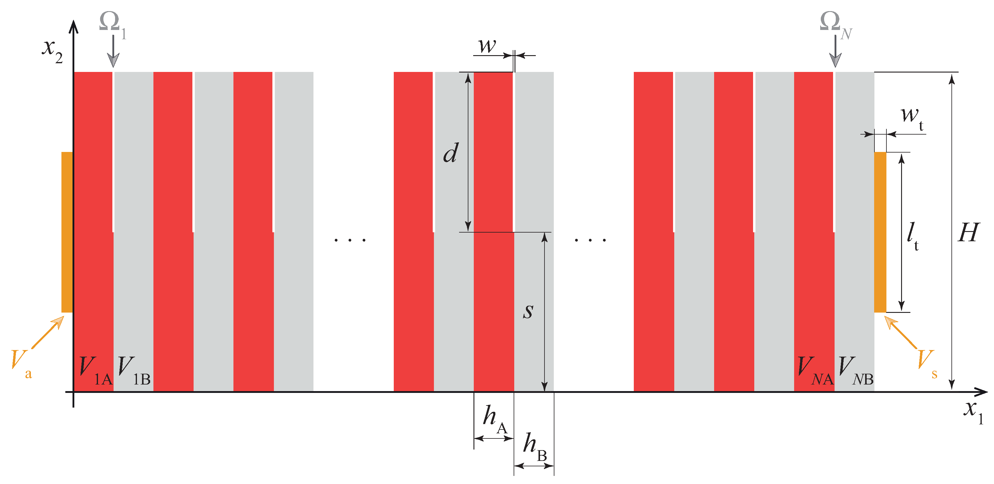
2.1. Design
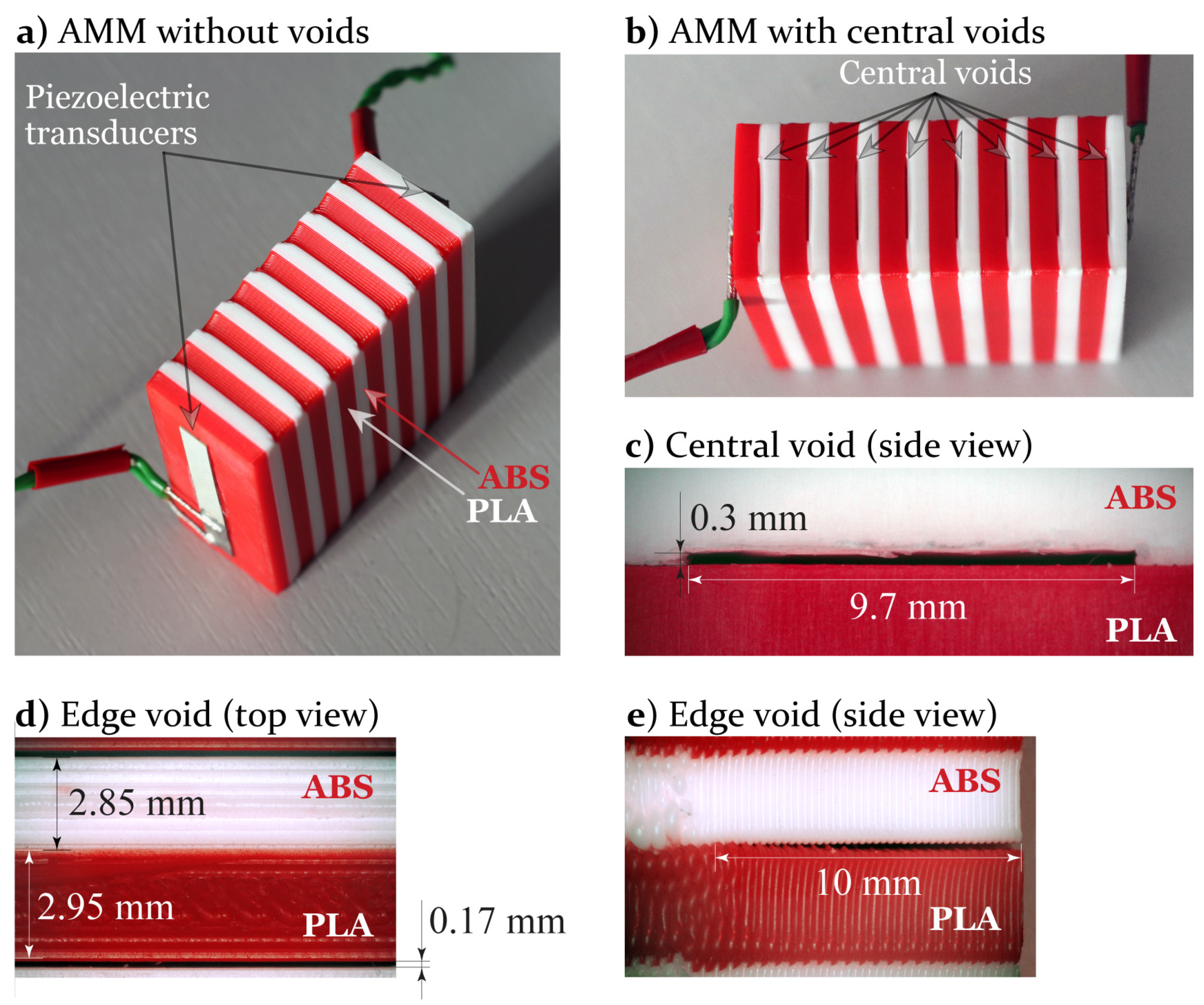
2.2. AMM Manufacturing
2.3. Experimental Setup
3. Simulation
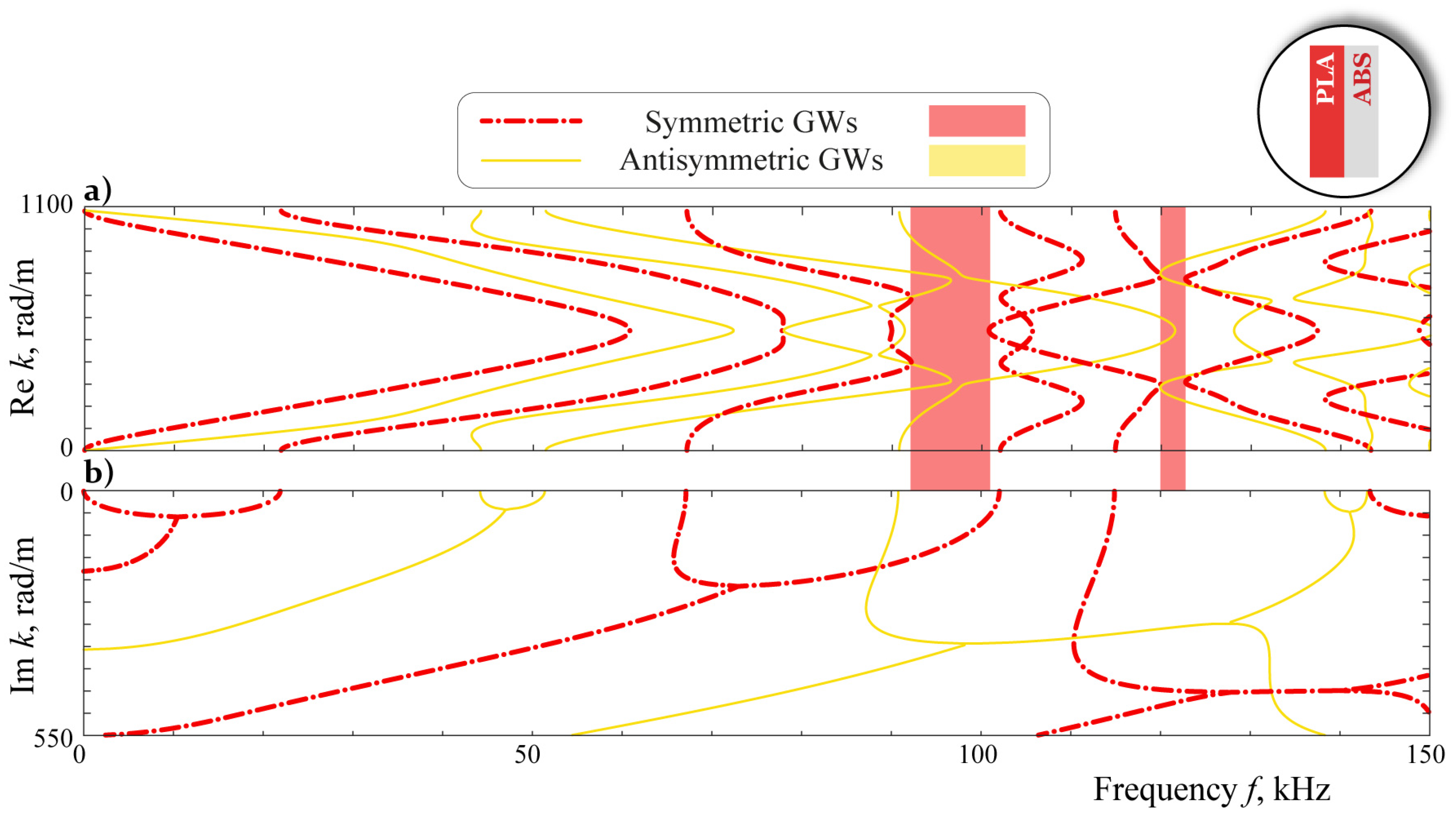
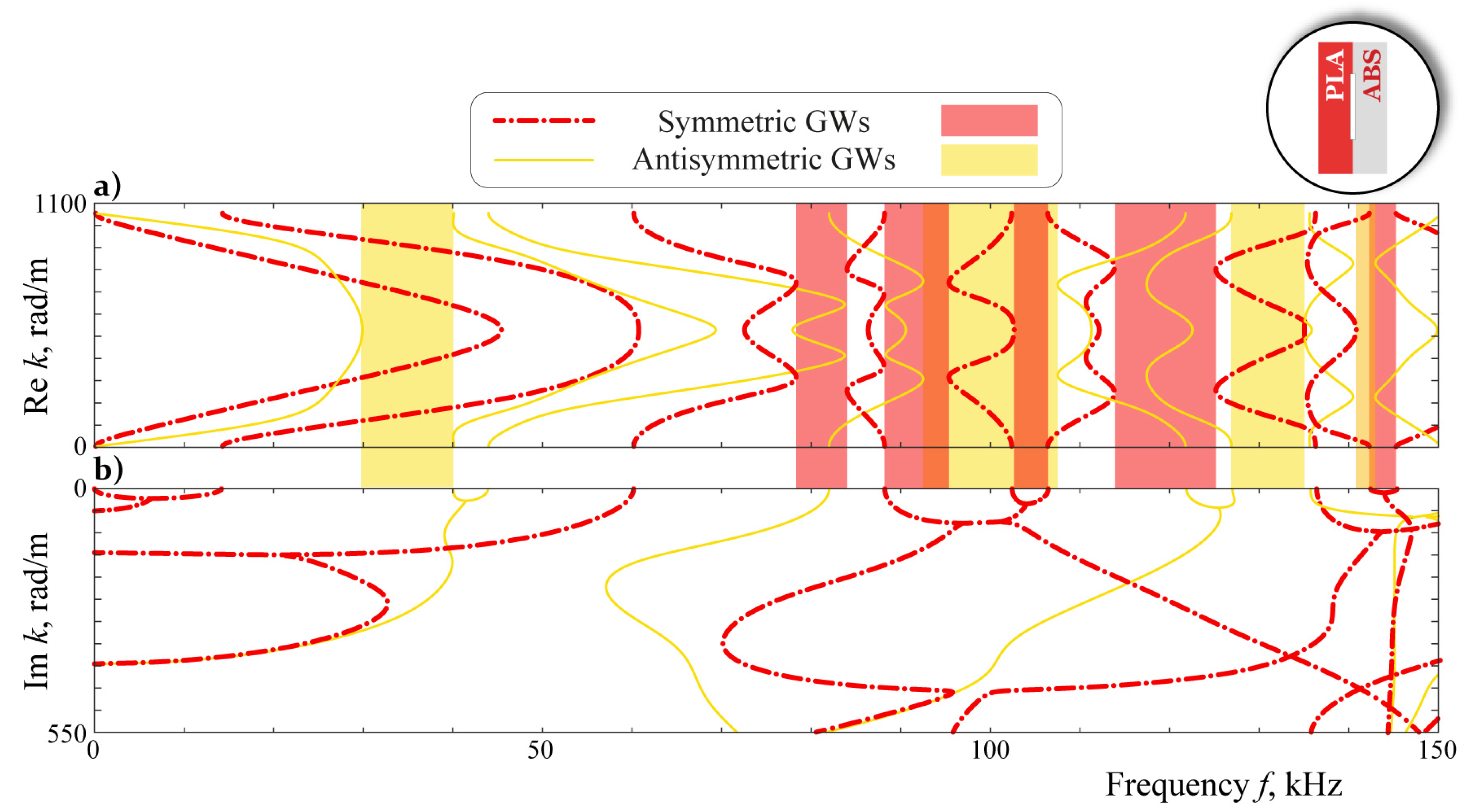
4. Analysis
5. Discussion
Author Contributions
Funding
Institutional Review Board Statement
Data Availability Statement
Acknowledgments
Conflicts of Interest
References
- Vasiliev, V.V.; Morozov, E.V. Advanced Mechanics of Composite Materials and Structures, 4th ed.; Elsevier: Amsterdam, The Netherlands, 2018; p. 882. [Google Scholar]
- Rubino, F.; Nisticò, A.; Tucci, F.; Carlone, P. Marine application of fiber reinforced composites: A review. J. Mar. Sci. Eng. 2020, 8, 26. [Google Scholar] [CrossRef] [Green Version]
- Wu, W.; Xia, R.; Qian, G.; Liu, Z.; Razavi, J.; Berto, F.; Gao, H. Mechanostructures: Rational mechanical design, fabrication, performance evaluation, and industrial application of advanced structures. Prog. Mater. Sci. 2023, 131, 101021. [Google Scholar] [CrossRef]
- Lu, M.H.; Feng, L.; Chen, Y.F. Phononic crystals and acoustic metamaterials. Mater. Today 2009, 12, 34–42. [Google Scholar] [CrossRef]
- Deymier, P. Acoustic Metamaterials and Phononic Crystals; Springer: Berlin/Heidelberg, Germany, 2013; p. 378. [Google Scholar]
- Ma, F.; Wang, C.; Liu, C.; Wu, J.H. Structural designs, principles, and applications of thin-walled membrane and plate-type acoustic/elastic metamaterials. J. Appl. Phys. 2021, 129, 231103. [Google Scholar] [CrossRef]
- Dogra, S.; Gupta, A. Design, manufacturing, and acoustical analysis of a Helmholtz resonator-based metamaterial plate. Acoustics 2021, 3, 630–641. [Google Scholar] [CrossRef]
- Kadic, M.; Milton, G.W.; van Hecke, M.; Wegener, M. 3D metamaterials. Nat. Rev. Phys. 2019, 1, 198–210. [Google Scholar] [CrossRef]
- Liao, G.; Luan, C.; Wang, Z.; Liu, J.; Yao, X.; Fu, J. Acoustic metamaterials: A review of theories, structures, fabrication approaches, and applications. Adv. Mater. Technol. 2021, 6, 2000787. [Google Scholar] [CrossRef]
- Du, Y.; Wu, W.; Chen, W.; Lin, Y.; Chi, Q. Control the structure to optimize the performance of sound absorption of acoustic metamaterial: A review. AIP Adv. 2021, 11, 060701. [Google Scholar] [CrossRef]
- Alam, Z.; Sharma, A.K. Functionally Graded Soft Dielectric Elastomer Phononic Crystals: Finite Deformation, Electro-Elastic Longitudinal Waves, and Band Gaps Tunability via Electro-Mechanical Loading. Int. J. Appl. Mech. 2022, 14, 2250050. [Google Scholar] [CrossRef]
- Dai, H.; Zhang, X.; Zheng, Y.; Pei, W.; Zhou, R.; Liu, R.; Gong, Y. Review and prospects of metamaterials used to control elastic waves and vibrations. Front. Phys. 2022, 10, 1179. [Google Scholar] [CrossRef]
- Yang, Z.; Mei, J.; Yang, M.; Chan, N.H.; Sheng, P. Membrane-type acoustic metamaterial with negative dynamic mass. Phys. Rev. Lett. 2008, 101, 204301. [Google Scholar] [CrossRef] [PubMed]
- Zhu, R.; Liu, X.; Hu, G.; Yuan, F.; Huang, G. Microstructural designs of plate-type elastic metamaterial and their potential applications: A review. Int. J. Smart Nano Mater. 2015, 6, 14–40. [Google Scholar] [CrossRef] [Green Version]
- Lee, M.K.; Kim, Y.Y. Add-on unidirectional elastic metamaterial plate cloak. Sci. Rep. 2016, 6, 20731. [Google Scholar] [CrossRef] [PubMed] [Green Version]
- Wang, W.; Bonello, B.; Djafari-Rouhani, B.; Pennec, Y.; Zhao, J. Double-negative pillared elastic metamaterial. Phys. Rev. Appl. 2018, 10, 064011. [Google Scholar] [CrossRef]
- Kanev, N. Resonant metasurfaces with a tangential impedance. Acoustics 2022, 4, 903–914. [Google Scholar] [CrossRef]
- Talonov, A.; Savatorova, V.; Vlasov, A. High-frequency approximation of plane wave propagation in an elastic medium with periodic distribution of cracks. Compos. Mech. Comput. Appl. 2017, 8, 339–354. [Google Scholar] [CrossRef]
- Chen, Z.; Wang, G.; Shi, F.; Lim, C. Analytical modeling and numerical analysis for tunable topological phase transition of flexural waves in active sandwiched phononic beam systems. Int. J. Mech. Sci. 2022, 223, 107292. [Google Scholar] [CrossRef]
- Achenbach, J.D.; Li, Z.L. Propagation of horizontally polarized transverse waves in a solid with a periodic distribution of cracks. Wave Motion 1986, 8, 371–379. [Google Scholar] [CrossRef]
- Su, X.; Norris, A.N. Focusing, refraction, and asymmetric transmission of elastic waves in solid metamaterials with aligned parallel gaps. J. Acoust. Soc. Am. 2016, 139, 3386–3394. [Google Scholar] [CrossRef] [Green Version]
- Su, X.; Lu, Z.; Norris, A.N. Elastic metasurfaces for splitting SV- and P-waves in elastic solids. J. Appl. Phys. 2018, 123, 091701. [Google Scholar] [CrossRef]
- Zhbadinskii, I.Y. Interaction of one-periodic disk-shaped cracks under an incident elastic harmonic wave. Mech. Solids 2016, 51, 127–134. [Google Scholar] [CrossRef]
- Mykhas’kiv, V.V.; Zhbadynskyi, I.Y.; Zhang, C. On propagation of time-harmonic elastic waves through a double-periodic array of penny-shaped cracks. Eur. J. Mech. A Solids 2019, 73, 306–317. [Google Scholar] [CrossRef]
- Remizov, M.Y.; Sumbatyan, M.A. Three-dimensional one-mode penetration of elastic waves through a doubly periodic array of cracks. Math. Mech. Solids 2018, 23, 636–650. [Google Scholar] [CrossRef]
- Sumbatyan, M.; Remizov, M. On 3D theory of acoustic metamaterials with a triple-periodic system of interior obstacles. Contin. Mech. Thermodyn. 2019, 31, 1743–1756. [Google Scholar] [CrossRef]
- Golub, M.V.; Doroshenko, O.V. Boundary integral equation method for simulation scattering of elastic waves obliquely incident to a doubly periodic array of interface delaminations. J. Comput. Phys. 2019, 376, 675–693. [Google Scholar] [CrossRef]
- Yan, Z.Z.; Zhang, C.; Wang, Y.S. Analysis of wave propagation and localization in periodic/disordered layered composite structures by a mass-spring model. Appl. Phys. Lett. 2009, 161909, 224303. [Google Scholar] [CrossRef]
- Golub, M.V.; Zhang, C. In-plane time-harmonic elastic wave motion and resonance phenomena in a layered phononic crystal with periodic cracks. J. Acoust. Soc. Am. 2015, 137, 238–252. [Google Scholar] [CrossRef] [PubMed]
- Golub, M.V.; Doroshenko, O.V.; Fomenko, S.I.; Wang, Y.; Zhang, C. Elastic wave propagation, scattering and localization in layered phononic crystals with arrays of strip-like cracks. Int. J. Solids Struct. 2021, 212, 1–22. [Google Scholar] [CrossRef]
- Huang, K.X.; Shui, G.S.; Wang, Y.Z.; Wang, Y.S. Meta-arrest of a fast propagating crack in elastic wave metamaterials with local resonators. Mech. Mater. 2020, 148, 103497. [Google Scholar] [CrossRef]
- Wang, Y.; Perras, E.; Golub, M.V.; Fomenko, S.I.; Zhang, C.; Chen, W. Manipulation of the guided wave propagation in multilayered phononic plates by introducing interface delaminations. Eur. J. Mech. A Solids 2021, 88, 104266. [Google Scholar] [CrossRef]
- Wang, Y.; Li, A.; Golub, M.V.; Huang, G.; Chen, W.; Zhang, C. Interfacial delamination induced unidirectional propagation of guided waves in multilayered media. Math. Mech. Solids 2022, 27, 1531–1545. [Google Scholar] [CrossRef]
- Zubov, Y.; Djafari-Rouhani, B.; Jin, Y.; Sofield, M.; Walker, E.; Neogi, A.; Krokhin, A. Long-range nonspreading propagation of sound beam through periodic layered structure. Commun. Phys. 2020, 3, 155. [Google Scholar] [CrossRef]
- Hedayatrasa, S.; Kersemans, M. 3D intra-cellular wave dynamics in a phononic plate with ultra-wide bandgap: Attenuation, resonance and mode conversion. Smart Mater. Struct. 2022, 31, 035010. [Google Scholar] [CrossRef]
- Tancogne-Dejean, T.; Diamantopoulou, M.; Gorji, M.B.; Bonatti, C.; Mohr, D. 3D plate-lattices: An emerging class of low-density metamaterial exhibiting optimal isotropic stiffness. Adv. Mater. 2018, 30. [Google Scholar] [CrossRef] [PubMed]
- Askari, M.; Hutchins, D.A.; Thomas, P.J.; Astolfi, L.; Watson, R.L.; Abdi, M.; Ricci, M.; Laureti, S.; Nie, L.; Freear, S.; et al. Additive manufacturing of metamaterials: A review. Addit. Manuf. 2020, 36. [Google Scholar] [CrossRef]
- Dhaliwal, G.S.; Dundar, M.A. Four point flexural response of acrylonitrile—Butadiene—Styrene. J. Compos. Sci. 2020, 4, 63. [Google Scholar] [CrossRef]
- Mirkhalaf, S.M.; Fagerström, M. The mechanical behavior of polylactic acid (PLA) films: Fabrication, experiments and modelling. Mech. Time-Depend. Mater. 2021, 25, 119–131. [Google Scholar] [CrossRef] [Green Version]
- Golub, M.V.; Doroshenko, O.V.; Arsenov, M.; Bareiko, I.; Eremin, A.A. Identification of material properties of elastic plate using guided waves based on the matrix pencil method and laser Doppler vibrometry. Symmetry 2022, 14, 1077. [Google Scholar] [CrossRef]
- Golub, M.V.; Doroshenko, O.V.; Arsenov, M.A.; Eremin, A.A.; Gu, Y.; Bareiko, I. Improved unsupervised learning method for material properties identification based on mode separation of ultrasonic guided wave. Computation 2022, 10, 93. [Google Scholar] [CrossRef]
- Guo, Y.; Liu, F.; Du, Q.; Peng, P. Total conversion between the longitudinal and transverse waves by an ultrathin elastic metamaterial plate with U-shaped slits. Appl. Phys. Express 2022, 15, 127002. [Google Scholar] [CrossRef]


| Material | Elastic Constants | Piezoelectric Constants [] | Dielectric Constants [] | Density [] |
|---|---|---|---|---|
| PLA | GPa | — | — | 1183 |
| ABS | GPa | — | — | 983 |
| PIC 155 | GPa | 7800 | ||
| GPa | ||||
| GPa | ||||
| GPa |
Disclaimer/Publisher’s Note: The statements, opinions and data contained in all publications are solely those of the individual author(s) and contributor(s) and not of MDPI and/or the editor(s). MDPI and/or the editor(s) disclaim responsibility for any injury to people or property resulting from any ideas, methods, instructions or products referred to in the content. |
© 2023 by the authors. Licensee MDPI, Basel, Switzerland. This article is an open access article distributed under the terms and conditions of the Creative Commons Attribution (CC BY) license (https://creativecommons.org/licenses/by/4.0/).
Share and Cite
Golub, M.V.; Moroz, I.A.; Wang, Y.; Khanazaryan, A.D.; Kanishchev, K.K.; Okoneshnikova, E.A.; Shpak, A.N.; Mareev, S.A.; Zhang, C. Design and Manufacturing of the Multi-Layered Metamaterial Plate with Interfacial Crack-like Voids and Experimental-Theoretical Study of the Guided Wave Propagation. Acoustics 2023, 5, 122-135. https://doi.org/10.3390/acoustics5010008
Golub MV, Moroz IA, Wang Y, Khanazaryan AD, Kanishchev KK, Okoneshnikova EA, Shpak AN, Mareev SA, Zhang C. Design and Manufacturing of the Multi-Layered Metamaterial Plate with Interfacial Crack-like Voids and Experimental-Theoretical Study of the Guided Wave Propagation. Acoustics. 2023; 5(1):122-135. https://doi.org/10.3390/acoustics5010008
Chicago/Turabian StyleGolub, Mikhail V., Ilya A. Moroz, Yanzheng Wang, Artur D. Khanazaryan, Kirill K. Kanishchev, Evgenia A. Okoneshnikova, Alisa N. Shpak, Semyon A. Mareev, and Chuanzeng Zhang. 2023. "Design and Manufacturing of the Multi-Layered Metamaterial Plate with Interfacial Crack-like Voids and Experimental-Theoretical Study of the Guided Wave Propagation" Acoustics 5, no. 1: 122-135. https://doi.org/10.3390/acoustics5010008