Article

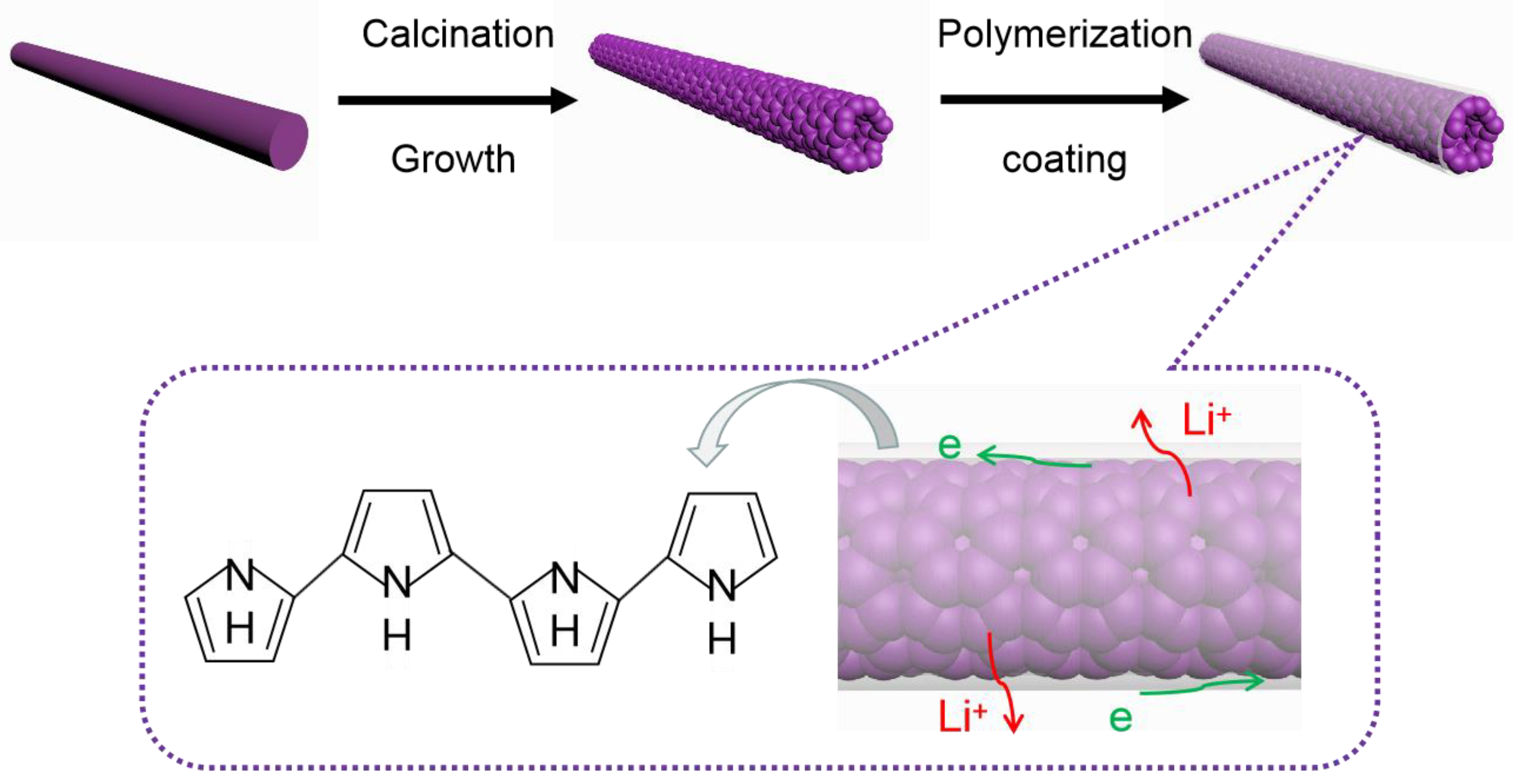
In Situ Gas-Phase Polymerization of Polypyrrole-Coated Lithium-Rich Nanotubes for High-Performance Lithium-Ion Batteries

1
Key Laboratory of Material Physics, School of Physics and Engineering, Zhengzhou University, Zhengzhou 450052, China
2
Physics and Electronic Engineering Department, Xinxiang University, Xinxiang 453000, China
3
School of Materials Science and Engineering, Zhejiang University, Hangzhou 310027, China
*
Authors to whom correspondence should be addressed.
Surfaces 2023, 6(1), 53-63; https://doi.org/10.3390/surfaces6010005
Submission received: 1 November 2022 / Revised: 14 February 2023 / Accepted: 15 February 2023 / Published: 22 February 2023
(This article belongs to the Collection Featured Articles for Surfaces)

Abstract

:
Conductive polymer polypyrrole (PPy)-coated lithium-rich manganese-based Li1.2Mn0.54Ni0.13Co0.13O2 (LMNCO) nanotube cathode materials were synthesized by electrospinning and subsequently subjected to low-temperature vapor-phase polymerization. X-ray diffraction (XRD), scanning electron microscopy (SEM) and high-resolution transmission electron microscopy (HRTEM) results confirm that the successful coating of the PPy layer (~2 nm) on the surface of LMNCO nanotubes did not destroy their morphologies or structures. Electrochemical tests indicate that the electrochemical performance of PPy-coated LMNCO nanotubes has been significantly enhanced. At a rate of 1 C, the discharge capacity of the PPy-coated LMNCO cell is 200.1 mAh g−1, and the capacity retention is 99% after 120 cycles. This excellent stability is attributed to the inhibition of side reactions and the protective function of the tubular structure due to the PPy coating layer. Additionally, the rate capability is also improved at a high current density due to the higher electronic and ionic conductivity.

1. Introduction

In recent years, high-energy density and low-cost cathode materials have become an urgent need for lithium-ion batteries. In this context, layered Li-rich manganese oxides (LLOs), with the chemical formula (xLi2MnO3·(1−x)LiMO2, M = Mn, Ni, Co, etc.), have attracted increasing attention due to their high reversible capacity, high operating voltage and low cobalt content [1,2,3,4]. Layered lithium-rich manganese cathodes are constructed by layering Li2MnO3 and LiMO2 components at the nanoscopic level. By charging them to high potentials (4.6–4.8 V), lithium can be extracted from the Li2MnO3 component, which leads to a high reversible capacity that can approach 300 mAh g−1, which is almost twice that of common cathode materials such as LiMn2O4, LiCoO2 and LiFePO4 [5,6,7,8]. Unfortunately, there are several critical problems that prevent their development for commercial batteries. First of all, the voltage of these high-voltage cathode compositions will drop during the cycle, and during the charge–discharge cycle, the transition-metal ions migrate from the transition-metal layer to the lithium layer, resulting in the structure of the material changing from layered to spinel and the discharge voltage decreasing, which affect the cycling performance of the material. In addition, these high-voltage cathode compositions have poor magnification performance at high magnification, because the electronic conductivity and ionic conductivity of lithium-rich basic manganese oxide are relatively low, and the electrons and lithium ions cannot be rapidly transported at a high current [9,10,11,12].
Many effective strategies have been adopted to address these drawbacks, such as ion doping [13,14,15,16], surface modification [17,18,19,20,21] and nanostructure morphology [22,23,24]. Among them, the nanostructure morphology has attracted much more attention due to its short lithium-diffusion pathways and abundant active sites. Ma et al. reported that one-dimensional (1D) nanotube structural cathodes can greatly improve the rate capability, and the specific capacity of Li1.2Mn0.54Ni0.13Co0.13O2 nanotubes can reach ~126 mAh g−1 at 5 C [23]. As is well known, these nanotube cathodes are assembled with nanosized grains, and their high specific area facilitates the efficient transport of lithium ions. However, at a high voltage, the severe side reactions between the electrolyte and electrode will lead to the deterioration of the structure of the nanotube cathode and lead to a general cyclic performance.
Surface coating is regarded as an effective method to alleviate side reactions. As previously reported, surface coating with metal oxides [17], fluorides [18] and phosphates [19] can enhance the stability of the interface and suppress the elimination of oxygen-ion vacancies. However, most of the above coating materials are inorganic, and these materials often present as discontinuous and inert layers, hindering the diffusion of electrons and lithium ions to some extent. Recently, organic polymers such as polypyrrole (PPy) and the biopolymer chitosan (CHIT) have been reported to improve the rate performance and cyclic stability of LiMn1/3Co1/3Ni1/3O2 [25] and CoMoO4 [26]. These organic materials are typical conductive polymers and have attracted much attention. Among them, PPy is characterized by simple synthesis, good biocompatibility, high electron conductivity and outstanding stability, and its excellent film-forming ability may contribute to highly continuous and nanometer-thick layers on the surfaces of active materials. Wu et al. [27] used the Pechini method to coat a layer of a ~10 nm thick PPy film on a Li1.2Mn0.54Ni0.13Co0.13O2 solid solution and found that the solid electrolyte interphase appeared on the LLOs after they were PPy-coated. However, they did not conduct sufficient research on the electrochemical performance or explain the mechanism.
In our work, we used a low-temperature vapor polymerization method to prepare PPy-coated Li1.2Mn0.54Ni0.13Co0.13O2 nanotubes. The sample synthesis process is shown in Figure 1. First, one-dimensional nanofiber cathode materials were prepared by electrospinning, and then the nanofiber cathode materials were calcined at a high temperature in an annealing furnace to prepare hollow and porous nanotube cathode materials. Finally, the nanotube cathode materials were put into a polypyrrole gas-phase polymerization device for vapor-phase coating, and the PPy-LMNCO composite materials were prepared. It is expected that this method can effectively combine the advantages of both a hollow nanotube structure and a nanocomposite conductive polymer strategy to maximize the electrochemical performance of the materials.

2. Materials and Methods

2.1. Preparation of Li1.2Mn0.54Co0.13Ni0.13O2 (LMNCO) Nanotubes

The one-dimensional LMNCO nanotube cathode was prepared by the electrospinning method. Polyacrylonitrile (PAN) and certain amounts of MnCH3COO·2H2O, Ni(CH3COO)2·4H2O, Co(CH3COO)2·4H2O and Li(CH3COO)2·4H2O were dissolved in 20 mL of N,N-dimethylformamide (DMF). Then, the salt solution was slowly dropped into the PAN solution under continuous stirring. Subsequently, the mixed solution was stirred for 20 h to form a homogeneous electrospinning solution. In the process of electrospinning, a high voltage of 15 kV, a flow rate of 1 mL h−1, a humidity of 25% and a distance of 200 mm between the collector and needle were used. The nanofiber precursor was collected on aluminum foil and dried for 6 h. Then, the dried samples were preheated at 500 °C for 4 h and calcined at 800 °C for 10 h in an air atmosphere.

2.2. Preparation of PPy-Coated Li1.2Mn0.54Co0.13Ni0.13O2 (P-LMNCO) Nanotubes

P-LMNCO was fabricated by in situ gas-phase polymerization. Firstly, 0.132 g of FeCl3 was dissolved in 20 mL of deionized water as an oxidant. The LMNCO nanotubes were immersed in an aqueous solution of FeCl3 for 5 min and then vacuum-filtered to obtain FeCl3-modified LMNCO nanotubes. Pure pyrrole was obtained after distillation under reduced pressure and placed in a polymerization chamber at a distillation temperature of 95 °C. Subsequently, FeCl3-modified LMNCO nanotubes were placed in a polymerization chamber filled with pyrrole vapor, and after 2 min, the final composites were obtained.

2.3. Characterization

The microstructures and morphologies of the nanotube cathode materials were examined by scanning electron microscopy (SEM) (JSM-6700F). The valence states of the metal elements were characterized by X-ray photoelectron spectroscopy (XPS, Thermo ESCALAB 250Xi). The X-ray diffraction (XRD) patterns were collected on a Bruker D8 advanced diffractometer. The microstructure and element distribution of P-LMNCO samples were examined by high-resolution transmission electron microscopy (HRTEM, JEOL JEM-2100F) with energy-dispersive X-ray spectroscopy (EDS).

2.4. Electrochemical Measurements

The electrodes were fabricated by milling a mixture of active material, PVDF and acetylene black at a mass ratio of 8:1:1. Then, the mixture was rolled into a film on an aluminum foil, and the coating thickness was about 2 mg cm−2. After drying at 120 °C for 12 h in a vacuum, the electrodes were pressed under a pressure of 25 Mpa and then assembled in CR-2032 coin cells. The cells were charged and discharged over a voltage range of 2.0–4.8 V on a battery station (CT-4008, Neware). Cyclic voltammetry (CV) (at a scan rate of 0.1 mV) and electrochemical impedance spectroscopy (EIS) were tested on a Bio-Logic electrochemical workstation, and EIS was performed with an amplitude of 5 mV and a frequency range from 0.1 MHz to 0.01 Hz. All of the above tests were performed at room temperature.

3. Results and Discussion

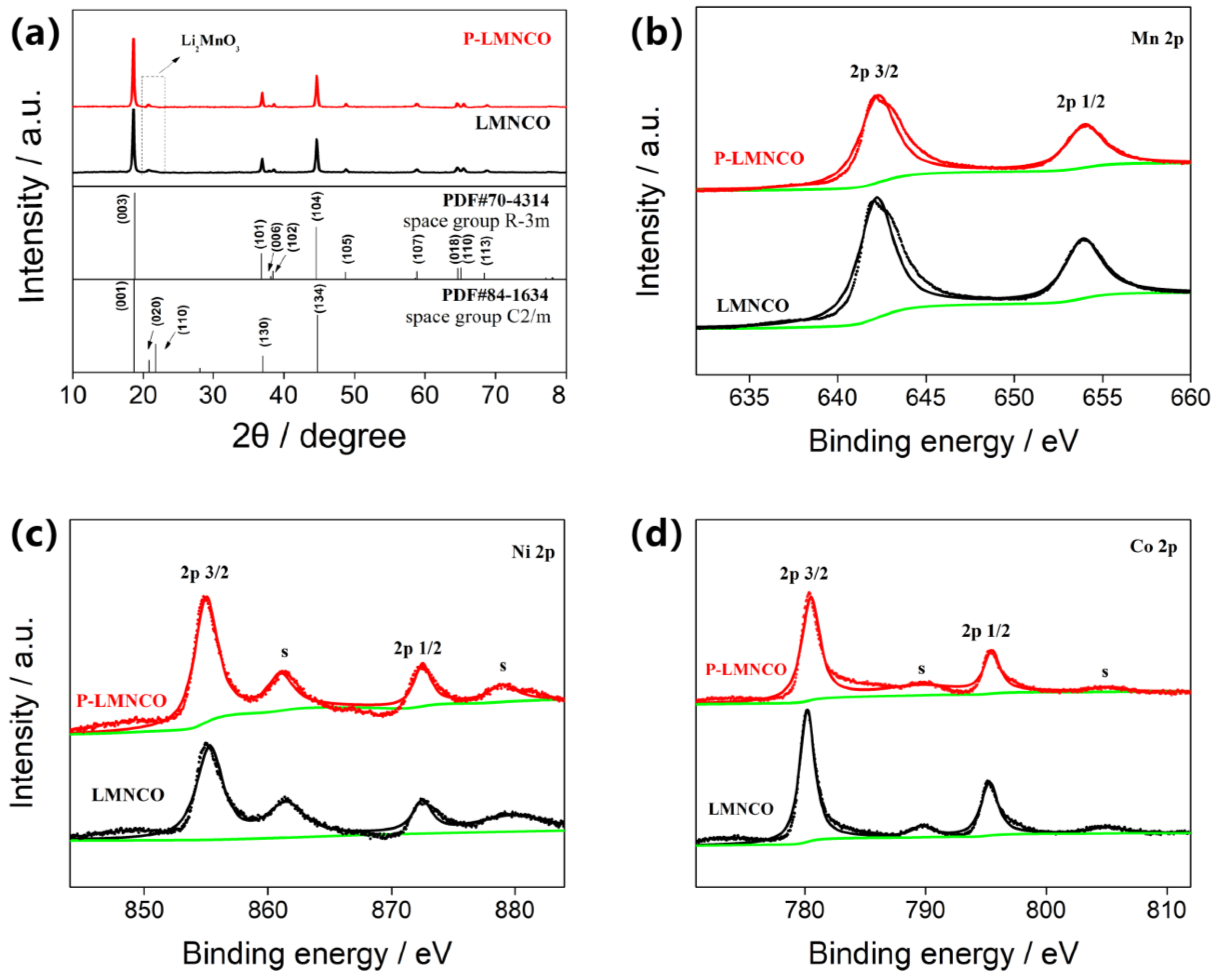
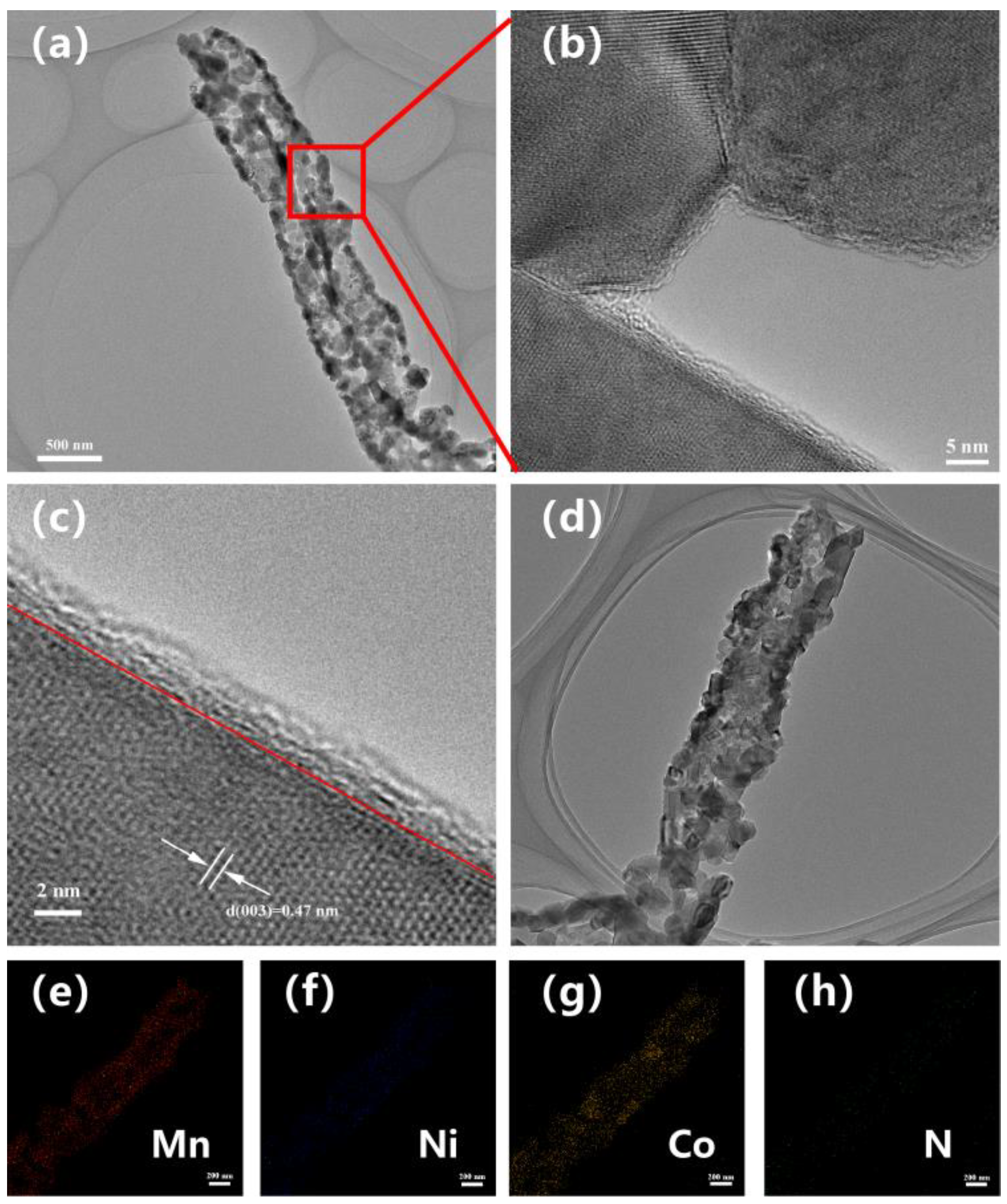
3.1. Morphology and Structure

Figure 2 shows the XRD patterns of LMNCO and P-LMNCO samples. Apparently, both of the patterns have fundamental diffraction peaks, which are ascribed to the layered component of the hexagonal α-NaFeO2 structure (space group: R3m). Additionally, no PPy peaks are observed in the pattern of the P-LMNCO sample, which may be due to PPy being an amorphous structure with a low content in the composite materials. It can be seen from Figure 2 that the small peaks of all samples from 20 to 23° are attributed to the superlattice diffraction of the monoclinic Li2MnO3 phase (space group: C2/m) [10,28]. Moreover, the diffraction peaks of the two samples are not substantially different, indicating that the PPy coating does change the crystal structure of the LMNCO nanofibers. As shown in Figure 2b–d, XPS measurements were performed to analyze the valence states of the transition-metal ions in the two samples. All binding energies were corrected for specimen charging by referencing them to the C 1s peak (284.6 eV). The peaks of Mn 2p3/2, Ni 2p3/2 and Co 2p3/2 in the two samples are close to those reported in Reference [20]. The chemical valences of Mn, Ni and Co ions in the two samples are +4, +3 and +2, respectively. These results indicate that the PPy coating has few effects on the valence of the main elements in the materials.
Figure 3 shows the FTIR spectra of the LMNCO and P-LMNCO samples. It can be seen from the figure that the absorption peak at 674 cm−1 is caused by hydroxyl, and the absorption peak at 3343 cm−1 is the characteristic absorption peak of water on the sample surface. Significantly, for the P-LMNCO sample, the absorption peaks at around 1539 cm−1 and 1401 cm−1 are caused by the antisymmetric and symmetric stretching vibrations of pyrrole rings, indicating that the PPy-coated Li1.2Mn0.54Ni0.13Co0.13O2 composites were successfully synthesized in this work.
To obtain a detailed structural characterization, TEM and HRTEM images of the P-LMNCO sample were obtained, as shown in Figure 4. The lattice spacing of 0.47 nm corresponds to the spacing between (003) planes of the layered lithium-rich cathode structure [21,29]. From the picture in Figure 4c, it can be clearly observed that a PPy layer about 2 nm thick is coated on the LMNCO surface, and these PPy coatings are quite continuous with no visible interruptions, revealing a perfect crystalline layered structure. The chemical composition of the coating layer in the P-LMNCO sample was examined using EDX elemental mapping (Figure 4e–h), which exhibits a uniform distribution of Mn, Ni, Co and N elements in the coating layer, indicating that the PPy film is uniformly coated on the surface of the LMNCO nanotubes.

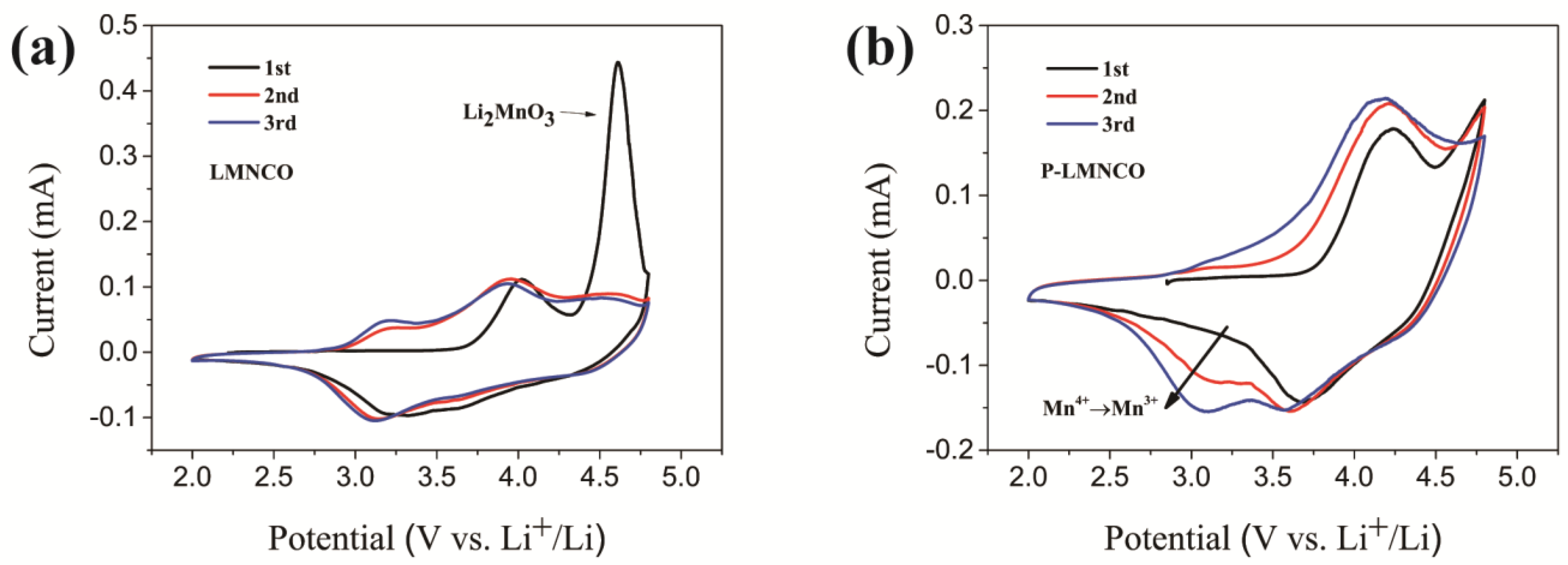
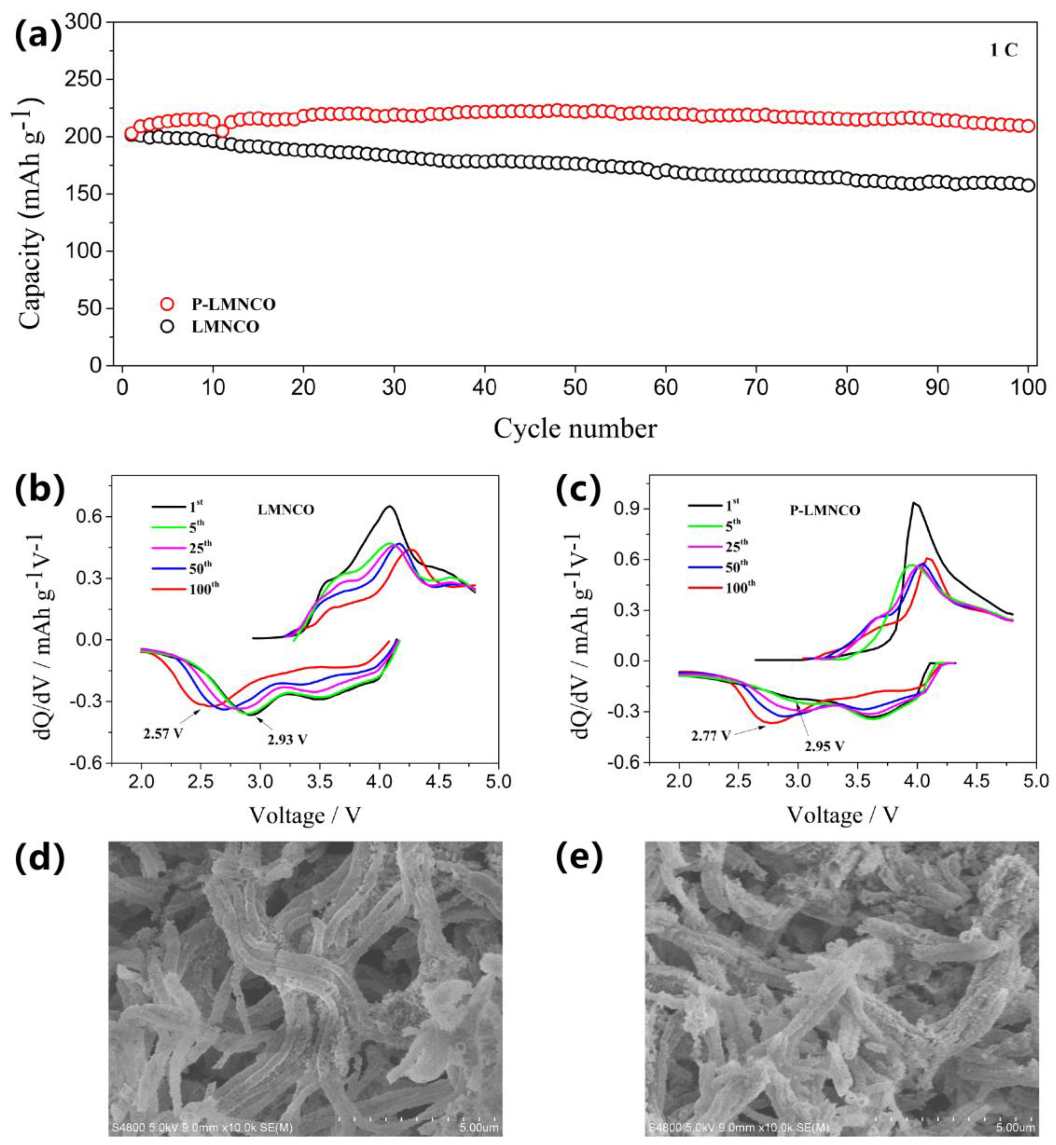
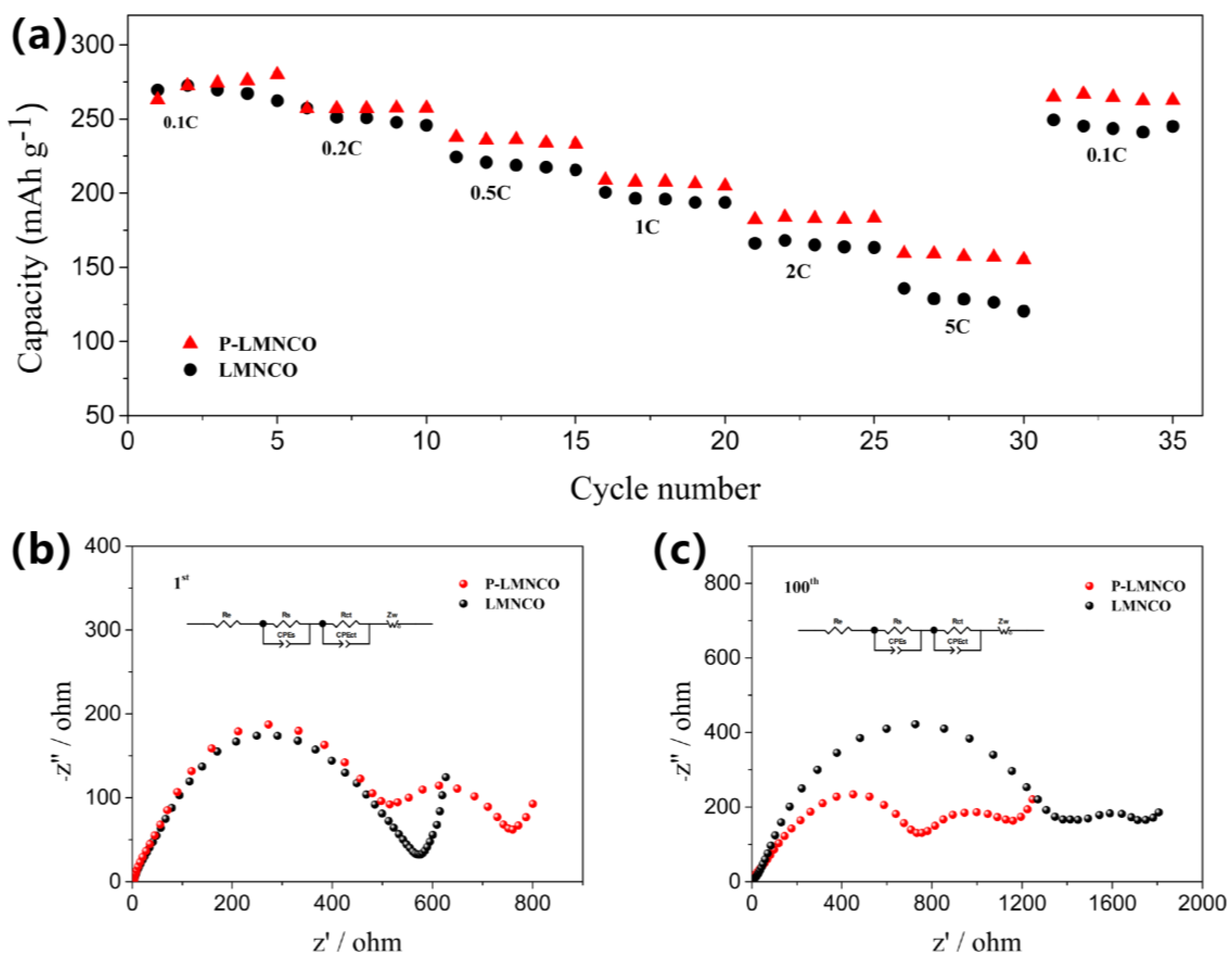
3.2. Electrochemical Performance

To investigate the electrochemical performance of the two samples, we performed the first three cyclic-voltammogram (CV) tests with a sweep rate of 0.1 mV s−1 between 2.0 V and 4.8 V (Figure 5a,b). In the first cycle, the oxidation peaks at approximately 4.0 V are attributed to the oxidation of Ni2+ to Ni3+ and Co3+ to Co4+, which correspond to the extraction of Li+ from LiMO2. Another oxidation peak at 4.6 V can be attributed to the extraction of Li2O from the Li2MnO3 component. In general, the Li2MnO3 component can provide an exceedingly high capacity, but it can also lead to more irreversible loss of O and Li by means of extracting Li2O. [17,30]. It is worth noting that the oxidation peak at around 4.6 V disappears in Figure 5b, indicating that electrolyte oxidation is suppressed after the PPy coating was applied. Significantly, for the P-LMNCO sample, the reduction peak at around 3.1 V is clearly observed until the third lap, corresponding to the redox of Mn3+/Mn4+ [27]. Although it was not confirmed that the PPy coating reduced oxygen release, it reduced the initial irreversible capacity loss and delayed the phase change process at least. The phase change speed becomes slow, which is beneficial to the stability of the material. Based on these results, it can be concluded that the proper PPy surface treatment of the original sample can reduce the irreversible loss of the initial capacity.
The polypyrrole-coated nanotube electrode shows an excellent cyclic performance. As shown in Figure 6a, the two electrodes were tested for 100 cycles of charging and discharging at 1 C (250 mAh g−1). The LMNCO electrodes delivered 201.5 mAh g−1 in the first charge, followed by a decrease to 157.5 mAh g−1 with a capacity retention of 78.2%. In contrast, the capacity of P-LMNCO increases from 202.8 to 209.3 mAh g−1 after 100 cycles. To investigate the electrochemical performance characteristics during cycling in depth, the 1st, 5th, 25th, 50th and 100th differential capacity curves of the two electrodes are provided in Figure 6b and Figure 6c. It is reported that the reduction peaks of Mn4+/Mn3+ from 2.5 V to 3.2 V are related to the structural degeneration from the layered phase to the spinel phase, which is mainly caused by transition-metal-ion migration blocking the transportation channel of Li+ [31,32]. For the LMNCO sample, the Mn4+/Mn3+ reduction peak decreases significantly from 2.93 V to 2.57 V (0.36 V) after 100 cycles. In contrast, the reduction peak of the P-LMNCO sample drops from 2.95 V to 2.77 V (0.18 V). It is obvious that the voltage decay of the surface-modified sample is suppressed. Moreover, transition-metal-ion migration will cause the reduction peaks of Ni4+/Ni2+ and Co4+/Co3+ to gradually disappear. Meanwhile, the polarization of the electrodes will increase accordingly [33,34]. By comparing LMNCO and P-LMNCO samples, it was found that the polarization of the P-LMNCO electrode was significantly lower than that of the LMNCO electrode after 100 cycles, which indicates that electrode polarization during the cycling of LMNCO nanotubes can be reduced by the polypyrrole coating.
To investigate the change in morphologies after the nanotube cathode circulation, the LMNCO cell and P-LMNCO cell after cycling 100 times were disassembled in an argon-filled glove box and then observed by SEM. As shown in Figure 6d,e, the morphology of the surface-modified sample is well maintained after the loop. In contrast, the tubular structures are almost invisible in the LMNCO sample, and the morphology of the pristine sample has been substantially destroyed and has collapsed. On the one hand, the high specific surface area of the nanotubes will aggravate the interfacial reaction between cathode materials and the electrolyte [35]. On the other hand, Li+ insertion/extraction during cycling will cause structural expansion and contraction. Furthermore, the change in the grain volume will affect the stability of the nanotube structure and cause the serious deterioration of the cycle performance [36]. The coating of polypyrrole can not only avoid direct contact between the material and the electrolyte but also help alleviate the structural volume change and stabilize the tubular structure [37,38].
Figure 7a shows the rate tests of pristine and surface-modified samples at incremental rates increasing from 0.1 to 5 C and recovering back to 0.1 C. Both electrodes showed similar discharge capacity at lower rates, but significant capacity differences occurred with increasing rates. At a rate of 5 C, the discharge capacities of LMNCO and P-LMNCO electrodes are 128.5 mAh g−1 and 159.8 mAh g−1, corresponding to 47.6% and 58.2% of the capacity at 0.1C. The outstanding rate performance of the P-LMNCO sample is attributed to the high electron conductivity of polypyrrole and the one-dimensional (1D) structural design.
Electrochemical impedance spectroscopy (EIS) tests of LMNCO and P-LMNCO cells were performed during the first cycle and after 100 cycles to identify the variations in impedance, as shown in Figure 7b,c. Rs corresponds to the semicircle associated with the diffusion of lithium ions through the SEI film in the high-frequency region. Rct corresponds to the semicircle related to the charge transfer process in the intermediate-frequency region. Re represents the electrolyte impedance, and the sloped straight line in the low-frequency range corresponds to Li+ diffusion in the bulk [39,40]. These impedance spectra were fitted and analyzed using Zsimpwin software, and the simulated electrochemical parameters are shown in Table 1. The initial Rs value of the P-LMNCO cell is 555.7 ohm, indicating the presence of the PPy coating layer, which is consistent with the results of Wu’s liquid-phase coating with PPy [27]. It is worth noting that the formation of the SEI layer during the cycle is due to the instability of the carbonate-based electrolyte under high pressure and the reactivity between the electrolyte and the charged LNMCO electrode, which causes the deterioration of the surface structure [41]. The SEI resistance of the LMNCO cell remarkably increases from 0.7 to 1528 ohm after 100 cycles, indicating severe electrolyte decomposition and the formation of a thick SEI layer during LMNCO cell cycling. On the contrary, the increase in the Rs value of the P-LMNCO cell is much smaller than that in the Rs value of the LMNCO cell. Apparently, with the PPy coating layer on the surface, the aggressive side reaction between the electrode and the electrolyte is effectively suppressed. In addition, in the case of the PPy coating, the charge transfer resistance of the P-LMNCO cell also has a significant drop. Consequently, the EIS results indicate that the PPy layer can separate electrode material from the electrolyte and effectively stabilize the electrolyte/electrode interface. Meanwhile, its high electronic conductivity is also beneficial in improving the electrochemical performance of LMNCO materials.

4. Conclusions

In this study, a low-vapor polymerization method was developed to prepare polypyrrole-coated LMNCO nanotubes. The PPy coating deposited with this gas-phase method is thinner (~2 nm) and more continuous than with the conventional liquid-phase method. The nanometer PPy coating can separate electrode material from the electrolyte, which not only suppresses the voltage drop and polarization during cycling but also protects the LMNCO tubular structure from destruction and collapse. Therefore, the cycle performance of materials has been significantly improved, and the capacity retention of the P-LMNCO sample is better than that of the LMNCO sample. At the same time, the high electronic conductivity of the PPy coating and low charge transfer resistance is beneficial in improving the rate capability. The discharge capacity of P-LMNCO at 5 C is 159.8 mAh g−1. Therefore, the Li1.2Mn0.54Co0.13Ni0.13O2@PPy nanotubes exhibit an excellent cyclic capability and improved rate performance. Our LMNCO@PPy nanotubes and this design concept provide an effective strategy for developing advanced cathode materials, which is significant for next-generation rechargeable lithium-ion batteries.

Author Contributions

Methodology, X.W. and J.C.; Project administration, L.Z. and J.X.; Supervision, B.S.; Writing—original draft, Y.C.; Writing—review & editing, X.W. and Y.C. All authors have read and agreed to the published version of the manuscript.

Funding

The authors gratefully acknowledge the financial support of the National Natural Science Foundation of China (No. 51802288), the China Postdoctoral Science Foundation (No. 2017M622369) and the Key Projects of Higher Education in Henan Province (No. 18A140008).

Acknowledgments

The authors gratefully acknowledge the financial support of the National Natural Science Foundation of China, the China Postdoctoral Science Foundation and the Key Projects of Higher Education in Henan Province.

Conflicts of Interest

The authors declare no conflict of interest.

References

  1. Csernica, P.M.; Kalirai, S.S.; Gent, W.E.; Lim, K.; Yu, Y.S.; Liu, Y.; Ahn, S.-J.; Kaeli, E.; Xu, X.; Stone, K.H. Persistent and partially mobile oxygen vacancies in Li-rich layered oxides. Nat. Energy 2021, 6, 642–652. [Google Scholar] [CrossRef]
  2. Zhang, J.; Zhang, Q.; Wong, D.; Zhang, N.; Ren, G.; Gu, L.; Schulz, C.; He, L.; Yu, Y.; Liu, X. Addressing voltage decay in Li-rich cathodes by broadening the gap between metallic and anionic bands. Nat. Commun. 2021, 12, 3071. [Google Scholar] [CrossRef]
  3. Yu, M.; Wei, X.; Min, X.; Yuan, A.; Xu, J. Graphene Quantum Dot Surface Coating for Improving the Electrochemical Performance of Li-Rich Li1.2Mn0.54Ni0.13Co0.13O2. Energy Fuels 2022, 36, 5502–5512. [Google Scholar] [CrossRef]
  4. Thackeray, M.; Kang, S.; Johnson, C.; Vaughey, J.; Hacknye, S. Li2MnO3-Stabilized LiMO2 (M = Mn, Ni, Co) Electrodes for Lithium-Ion Batteries. J. Mater. Chem. 2007, 17, 3112–3125. [Google Scholar] [CrossRef]
  5. Johnson, C.; Li, N.; Lefief, C.; Thackeray, M. Anomalous capacity and cycling stability of xLi2MnO3·(1 − x) LiMO2 electrodes (M = Mn, Ni, Co) in lithium batteries at 50 C. Electrochem. Commun. 2007, 9, 787–795. [Google Scholar] [CrossRef]
  6. Johnson, C.; Li, N.; Lefief, C.; Vaughey, J.; Thackeray, M. Synthesis, Characterization and Electrochemistry of Lithium Battery Electrodes: xLi2MnO3·(1 − x)LiMn0.333Ni0.333Co0.333O2 (0 ≤ x ≤ 0.7). Chem. Mater. 2008, 20, 6095–6106. [Google Scholar] [CrossRef]
  7. Liu, Z.; Wu, Y.; Huo, H.; Jian, J.; Sun, D.; Zhang, X.; Du, C.; Zuo, P.; Yin, G.; Ma, Y. Surface-Phase Engineering via Lanthanum Doping Enables Enhanced Electrochemical Performance of Li-Rich Layered Cathode. ACS Appl. Energy Mater. 2022, 5, 9648–9656. [Google Scholar] [CrossRef]
  8. Li, W.Y.; Zhao, B.C.; Bai, J.; Ma, H.Y.; Li, K.Z.; Wang, P.Y.; Mao, Y.J.; Zhu, X.B.; Sun, Y.P. Rate Performance Modification of a Lithium-Rich Manganese-Based Material through Surface Self-Doping and Coating Strategies. Langmuir 2021, 37, 3223–3230. [Google Scholar] [CrossRef] [PubMed]
  9. Ma, Y.; Zhou, Y.; Du, C.; Zuo, P.; Cheng, X.; Han, L.; Nordlund, D.; Gao, Y.; Yin, G.; Xin, H.L. A New Anion Receptor for Improving the Interface between Lithium- and Manganese-Rich Layered Oxide Cathode and the Electrolyte. Chem. Mat. 2017, 29, 2141–2149. [Google Scholar] [CrossRef] [Green Version]
  10. Wu, B.; Yang, X.; Jiang, X.; Zhang, Y.; Shu, H.; Gao, P.; Liu, L.; Wang, X. Synchronous Tailoring Surface Structure and Chemical Composition of Li-Rich–Layered Oxide for High-Energy Lithium-Ion Batteries. Adv. Funct. Mater. 2018, 28, 1803392. [Google Scholar] [CrossRef]
  11. Dixit, H.; Zhou, W.; Idrobo, J.; Nanda, J.; Cooper, V. Facet-dependent disorder in pristine high-voltage lithium-manganese-rich cathode material. ACS Nano. 2014, 8, 12710–12716. [Google Scholar] [CrossRef]
  12. Wu, W.; Sun, Z.; He, Q.; Shi, X.; Ge, X.; Cheng, J.; Zhang, Z. Boosting Lithium-Ion Transport Kinetics by Increasing the Local Lithium-Ion Concentration Gradient in Composite Anodes of Lithium-Ion Batteries. ACS Appl. Mater. Interfaces 2021, 13, 14752–14758. [Google Scholar] [CrossRef]
  13. Ahn, J.; Kim, J.; Cho, B.; Chung, K.; Kim, S.; Choi, J.; Oh, S. Nanoscale Zirconium-Abundant Surface Layers on Lithium- and Manganese-Rich Layered Oxides for High-Rate Lithium-Ion Batteries. Nano Lett. 2017, 17, 7869–7877. [Google Scholar] [CrossRef] [PubMed]
  14. Sun, Z.; Xu, L.; Dong, C.; Zhang, H.; Zhang, M.; Liu, Y. Enhanced cycling stability of boron-doped lithium-rich layered oxide cathode materials by suppressing transition metal migration. J. Mater. Chem. A 2019, 7, 3375–3383. [Google Scholar] [CrossRef]
  15. Chen, S.; Chen, Z.; Xia, M.; Cao, C.; Luo, Y. Toward Alleviating Voltage Decay by Sodium Substitution in Lithium-Rich Manganese-Based Oxide Cathodes. ACS Appl. Energy Mater. 2018, 1, 4065–4074. [Google Scholar] [CrossRef]
  16. Yang, H.; Wu, H.; Ge, M.; Li, L.; Yuan, Y.; Yao, Q.; Lu, J. Simultaneously Dual Modification of Ni-Rich Layered Oxide Cathode for High-Energy Lithium-Ion Batteries. Adv. Funct. Mater. 2019, 29, 1808825. [Google Scholar] [CrossRef]
  17. Chen, Y.; Wang, X.; Zhang, J.; Chen, B.; Xu, J.; Zhang, S.; Zhang, L. Al2O3-coated Li1.2Mn0.54Ni0.13Co0.13O2 nanotubes as cathode materials for high-performance lithium-ion batteries. RSC Adv. 2019, 9, 2172–2179. [Google Scholar] [CrossRef] [Green Version]
  18. Zhao, S.; Sun, B.; Yan, K.; Zhang, J.; Wang, C.; Wang, G. Aegis of Lithium-Rich Cathode Materials via Hetero structured LiAlF4 Coating for High-Performance Lithium-Ion Batteries. ACS Appl. Mater. Interfaces 2018, 10, 33260–33268. [Google Scholar] [CrossRef]
  19. Zhou, M.; Zhao, J.; Wang, X.; Shen, J.; Tang, W.; Deng, Y.; Liu, R. Surface engineering for high stable lithium-rich manganese-based cathode materials. Chin. Chem. Lett. 2022, 107793, 1001–8417. [Google Scholar] [CrossRef]
  20. Shang, H.; Ning, F.; Li, B.; Zuo, Y.; Lu, S.; Xia, D. Suppressing Voltage Decay of a Lithium-Rich Cathode Material by Surface Enrichment with Atomic Ruthenium. ACS Appl. Mater. Interfaces 2018, 10, 21349–21355. [Google Scholar] [CrossRef]
  21. Liu, H.; Chen, C.; Du, C.; He, X.; Yin, G.; Song, B.; Gao, Y. Lithium-Rich Li1.2Ni0.13Co0.13Mn0.54O2 Oxide Coated by Li3PO4 and Carbon Nanocomposite Layer as a High Performance Cathode Material for Lithium Ion Batteries. J. Mater. Chem. A 2014, 3, 2634–2641. [Google Scholar] [CrossRef]
  22. Yang, F.; Liu, Y.; Martha, S.; Wu, Z.; Andrews, J.; Ice, G.; Nanda, J. Nanoscale morphological and chemical changes of high voltage lithium-manganese rich NMC composite cathodes with cycling. Nano Lett. 2014, 14, 4334–4341. [Google Scholar] [CrossRef] [Green Version]
  23. Ma, D.; Li, Y.; Zhang, P.; Cooper, A.; Abdelkader, A.; Ren, X.; Deng, L. Mesoporous Li1.2Ni0.13Co0.13Mn0.54O2 nanotubes for high-performance cathodes in Li-ion batteries. J. Power Sources 2016, 311, 35–41. [Google Scholar] [CrossRef]
  24. Luo, K.; Roberts, M.; Hao, R.; Guerrini, N.; Liberti, E.; Allen, C.; Bruce, P. One-pot Synthesis of Lithium-rich Cathode Material with Hierarchical Morphology. Nano Lett. 2016, 16, 7503–7508. [Google Scholar] [CrossRef] [Green Version]
  25. Park, J.; Cho, J.; Kim, S.; Kim, W.; Lee, S.; Lee, S. A novel ion-conductive protection skin based on polyimide gel polymer electrolyte: Application to nanoscale coating layer of high voltage LiNi1/3Co1/3Mn1/3O2 cathode materials for lithium-ion batteries. J. Mater. Chem. 2012, 22, 12574–12581. [Google Scholar] [CrossRef]
  26. Ramkumar, R.; Minakshi Sundaram, M. A biopolymer gel-decorated cobalt molybdate nanowafer: Effective graft polymer cross-linked with an organic acid for better energy storage. New J. Chem. 2016, 40, 2863–2877. [Google Scholar] [CrossRef]
  27. Wu, C.; Fang, X.; Guo, X.; Mao, Y.; Ma, J.; Zhao, C.; Chen, L. Surface modification of Li1.2Ni0.13Co0.13Mn0.54O2 with conducting polypyrrole. J. Power Sources 2013, 231, 44–49. [Google Scholar] [CrossRef]
  28. Yin, E.; Grimaud, A.; Rousse, G.; Abakumov, A.; Senyshyn, A.; Zhang, L.; Tarascon, J. Structural evolution at the oxidative and reductive limits in the first electrochemical cycle of Li1.2Ni0.13Co0.13Mn0.54O2. Nat. Commun. 2020, 11, 1252. [Google Scholar] [CrossRef] [PubMed] [Green Version]
  29. Yu, R.; Zhang, X.; Liu, T.; Yang, L.; Liu, L.; Wang, Y.; Yang, X. Spinel/Layered Heterostructured Lithium-Rich Oxide Nanowires as Cathode Material for High-Energy Lithium-Ion Batteries. ACS Appl. Mater. Interfaces 2017, 9, 41210–41223. [Google Scholar] [CrossRef]
  30. Minakshi, M.; Sharma, N.; Ralph, D.; AppAdoo, D.; Nallathamby, K. Synthesis and Characterization of Li(CO0.5Ni0.5)PO4 Cathode for Li-Ion Aqueous Battery Applications. Electro. Solid-State Lett. 2011, 14, A86–A89. [Google Scholar] [CrossRef]
  31. Li, B.; Yan, H.; Ma, J.; Yu, P.; Xia, D.; Huang, W.; Wu, Z. Manipulating the Electronic Structure of Li-Rich Manganese-Based Oxide Using Polyanions: Towards Better Electrochemical Performance. Adv. Funct. Mater. 2014, 24, 5112–5118. [Google Scholar] [CrossRef]
  32. Gu, M.; Belharouak, I.; Zheng, J.; Wu, H.; Xiao, J.; Genc, A.; Wang, C. Formation of the spinel phase in the layered composite cathode used in Li-ion batteries. ACS Nano 2013, 7, 760–767. [Google Scholar] [CrossRef] [PubMed]
  33. Kumar Nayak, P.; Grinblat, J.; Levi, E.; Penki, T.; Levi, M.; Sun, Y.; Aurbach, D. Remarkably Improved Electrochemical Performance of Li- and Mn-Rich Cathodes upon Substitution of Mn with Ni. ACS Appl. Mater. Interfaces 2017, 9, 4309. [Google Scholar] [CrossRef] [PubMed]
  34. Yu, R.; Wang, G.; Liu, M.; Zhang, X.; Wang, X.; Shu, H.; Huang, W. Mitigating voltage and capacity fading of lithium-rich layered cathodes by lanthanum doping. J. Power Sources 2016, 335, 65–75. [Google Scholar] [CrossRef] [Green Version]
  35. Yang, Z.; Yuan, Y.; Zhu, M.; Yin, S.; Cheng, J.; Guo, S. Superior rate-capability and long-lifespan carbon nanotube-in-nanotube@Sb2S3 anode for lithium-ion storage. J. Mater. Chem. A 2021, 9, 22334–22346. [Google Scholar] [CrossRef]
  36. Ma, D.; Li, Y.; Wu, M.; Deng, L.; Ren, X.; Zhang, P. Enhanced cycling stability of Li-rich nanotube cathodes by 3D graphene hierarchical architectures for Li-ion batteries. Acta Mater. 2016, 112, 11–19. [Google Scholar] [CrossRef]
  37. Zhao, W.; Shi, Z.; Qi, Y.; Cheng, J. The Carbon-Coated ZnCo2O4 Nanowire Arrays Pyrolyzed from PVA for Enhancing Lithium Storage Capacity. Processes 2020, 8, 1501. [Google Scholar] [CrossRef]
  38. He, Q.; Sun, Z.; Shi, X.; Wu, W.; Cheng, J.; Zhuo, R.; Wang, J. Electrochemical Performance Enhancement of Nitrogen-Doped TiO2 for Lithium-Ion Batteries Investigated by a Film Electrode Model. Energy Fuels 2021, 35, 2717–2726. [Google Scholar] [CrossRef]
  39. Zhu, Z.; Yu, D.; Yang, Y.; Su, C.; Huang, Y.; Dong, Y.; Li, J. Gradient Li-rich oxide cathode particles immunized against oxygen release by a molten salt treatment. Nat. Energy 2019, 4, 1049–1058. [Google Scholar] [CrossRef]
  40. House, R.A.; Marie, J.J.; Pérez-Osorio, M.A.; Rees, G.J.; Boivin, E.; Bruce, P.G. The role of O2 in O-redox cathodes for Li-ion batteries. Nat. Energy 2021, 6, 781–789. [Google Scholar] [CrossRef]
  41. Batool, S.A.; Salman Maqbool, M.; Javed, M.A.; Niaz, A.; Rehman, M.A.U. A Review on the Fabrication and Characterization of Titania Nanotubes Obtained Via Electrochemical Anodization. Surfaces 2022, 5, 456–480. [Google Scholar] [CrossRef]
Figure 1. Schematic diagram of the route used to synthesize PPy-coated Li-rich nanotubes.
Surfaces 06 00005 g001
Figure 2. (a) The XRD patterns of LMNCO and P-LMNCO. XPS spectra of (b) Mn 2p, (c) Ni 2p and (d) Co 2p of LMNCO and P-LMNCO.
Surfaces 06 00005 g002
Figure 3. The FTIR spectra of LMNCO and P-LMNCO.
Surfaces 06 00005 g003
Figure 4. (ad) HRTEM images of P-LMNCO sample. (eh) EDX mapping of P-LMNCO sample.
Surfaces 06 00005 g004
Figure 5. Cyclic-voltammograms of (a) LMNCO and (b) P-LMNCO.
Surfaces 06 00005 g005
Figure 6. (a) Cyclic stability performance. The differential capacity curves (dQ/dV vs. V) of (b) LMNCO and (c) P-LMNCO; FE-SEM images of (d) LMNCO and (e) P-LMNCO.
Surfaces 06 00005 g006
Figure 7. (a) Rate capacities of LMNCO and P-LMNCO. Nyquist plots of LMNCO (b) and P-LMNCO (c) samples.
Surfaces 06 00005 g007
Table 1. The electrochemical impedance parameters of LMNCO and P-LMNCO.
1st 100th
SampleRe (ohm)Rs (ohm)Rct (ohm)Re (ohm)Rs (ohm)Rct (ohm)
LMNCO2.20.719559.02.91528.0402.7
P-LMNCO2.0555.7162.32.5886.9192.6
Disclaimer/Publisher’s Note: The statements, opinions and data contained in all publications are solely those of the individual author(s) and contributor(s) and not of MDPI and/or the editor(s). MDPI and/or the editor(s) disclaim responsibility for any injury to people or property resulting from any ideas, methods, instructions or products referred to in the content.

