Article

Mortar Characterization of Historical Masonry Damaged by Riverbank Failure: The Case of Lungarno Torrigiani (Florence)

1
Department of Earth Sciences, University of Florence, 50121 Florence, Italy
2
Department of Chemistry Ugo Schiff, University of Florence, 50019 Florence, Italy
*
Author to whom correspondence should be addressed.
Heritage 2023, 6(5), 3820-3834; https://doi.org/10.3390/heritage6050203
Submission received: 29 March 2023 / Revised: 19 April 2023 / Accepted: 20 April 2023 / Published: 22 April 2023
(This article belongs to the Special Issue Conservation Methodologies and Practices for Built Heritage)

Abstract

:
The research of structural masonry associated with geo-hydrological hazards in Cultural Heritage is a multidisciplinary issue, requiring consideration of several aspects including the characterization of used materials. On 25 May 2016, loss of water from the subterranean pipes and of the aqueduct caused an Arno riverbank failure damaging a 100 m long portion of the historical embankment wall of Lungarno Torrigiani in Florence. The historical masonry was built from 1854–1855 by Giuseppe Poggi and represents a historical example of an engineering approach to riverbank construction, composed of a scarp massive wall on foundation piles, with a rubble masonry internal core. The failure event caused only a cusp-shaped deformation to the wall without any shattering or toppling. A complete characterization of the mortars was performed to identify the technologies, raw materials and state of conservation in order to understand why the wall has not collapsed. Indeed, the mortars utilized influenced the structural behavior of masonry, and their characterization was fundamental to improve the knowledge of mechanical properties of civil architectural heritage walls. Therefore, the aim of this research was to analyze the mortars from mineralogical–petrographic, physical and mechanical points of view, to evaluate the contribution of the materials to damage events. Moreover, the results of this study helped to identify compatible project solutions for the installation of hydraulically and statically functional structures to contain the riverbank.

1. Introduction

The construction of riverbanks to defend cities began in ancient times. The reasons for construction were linked, on the one hand to the recurrence of disastrous floods and on the other to the expansion of anthropized zones. The current morphology of the Arno river in Florence is the result of typical urbanization of cities that develop along rivers, with the construction of retaining walls and the reduction of the river section [1,2]. The proximity of a river to civil structures and historical center provides a strong reason for detailed stability evaluation [3,4], considering the damage that the failure of the riverbanks could cause. Lungarno Torrigiani is a section of Florentine riverbank, located on the left side, 200 m long and near Ponte Vecchio. Like most of the Florentine riverbanks, it dates back to specific urban redevelopment, started between 1854–1855 (the realization of the “Lungarno Nuovo”) and completed during the “Piano Particolareggiato” interventions of the Florence Capital (1866–1872).
On 25 May 2016 a riverbank failure damaged a portion of the 100 m long historical embankment wall of Lungarno Torrigiani [5].
The displacement of the wall towards the river was about 3 m, with an extension of about 80 m, forming a chasm with a maximum depth of 3.5 m [6]. However, the failure exceptionally did not lead to the collapse of the riverbank, and the structure and the materials used in manufacture remained standing [7].
For this reason, comprehensive study of the riverbank was carried out, focusing on the construction technique and materials used in the original project. Mineralogical–petrographic, physical and mechanical characteristics of mortar were identified. These properties of the building materials are fundamental to evaluate their durability, decay phenomena and service life [8,9,10].
The analysis related to historical masonry walls is a task to be approached from several aspects. It is indeed necessary to obtain information about the inner core of the structural elements, identifying the mechanical properties of materials that can change greatly from point to point. In addition, the type of mortar used in the realization of its masonry can also influence the performance of the wall, due to the weathering products that can form and which can affect the durability of the structure [11,12]. Therefore, the masonry should be able to accommodate some degree of movement from creep or thermal effects without cracking, and must be sufficiently strong to develop appropriate adhesion between the elements.
Therefore the aim of this work was to study the mortars of the damaged wall of Lungarno Torrigiani from mineralogical–petrographic, physical and mechanical points of view, in order to identify and to explain their overall characteristics, understanding how the walls resisted the collapse; the results were compared with other two Lungarni of Florence, Lungarno degli Acciauoli and Lungarno delle Grazie as described in the paper of Calandra et al., 2022 [13], in order to understand the differences between the various riversides.

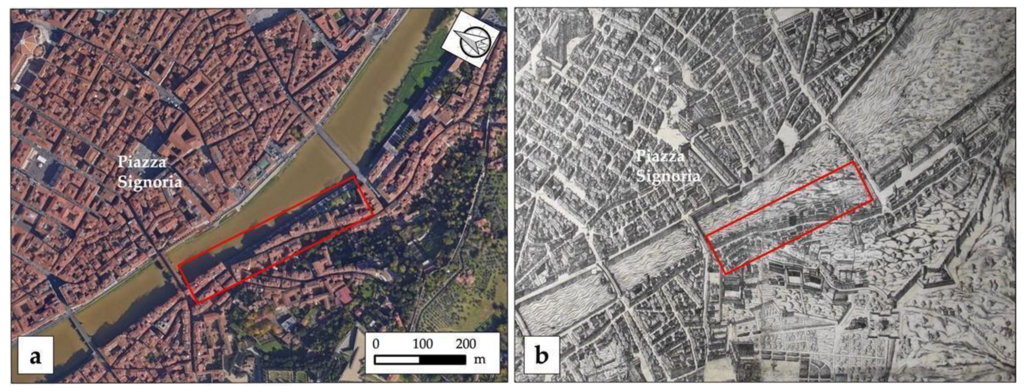
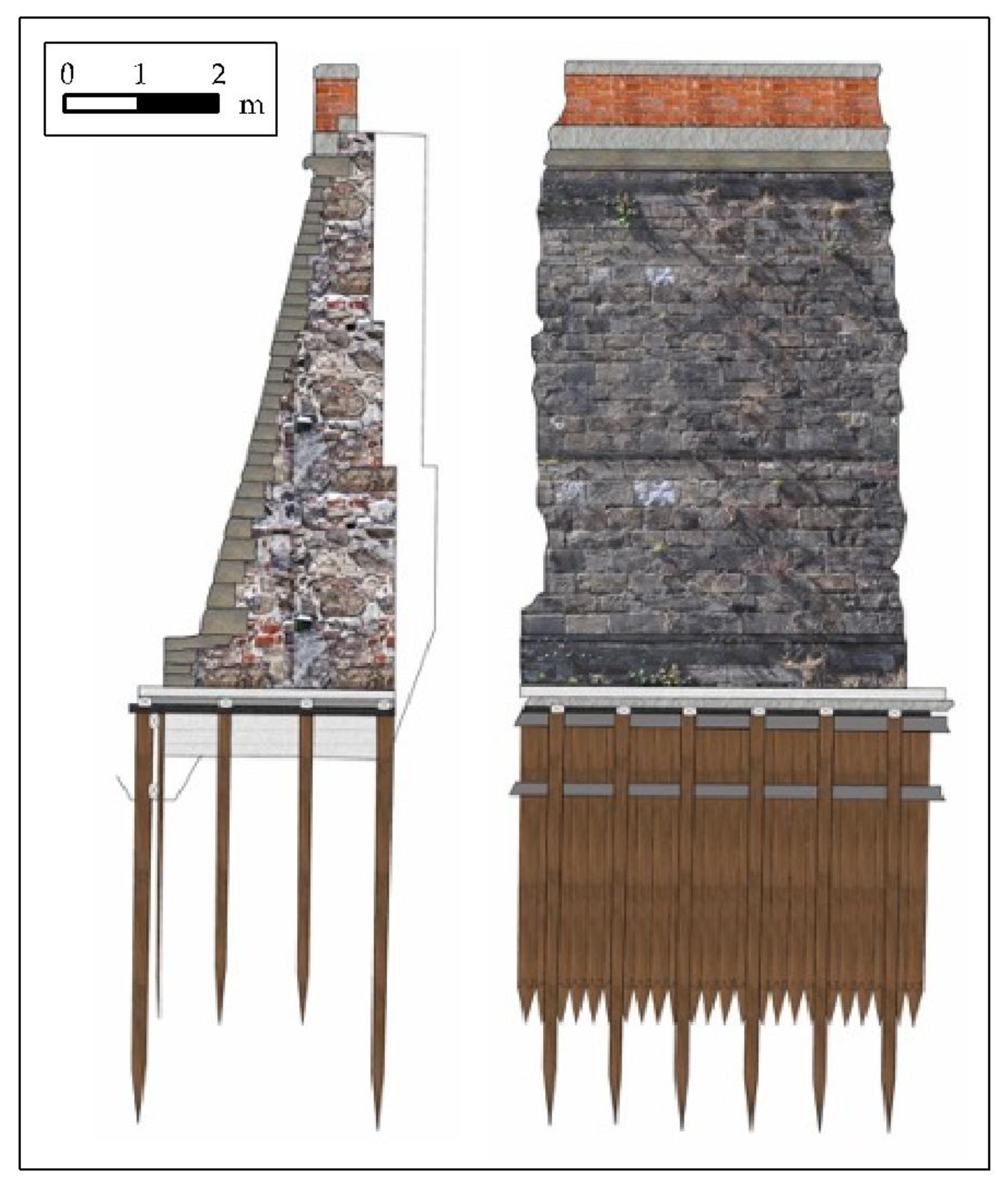
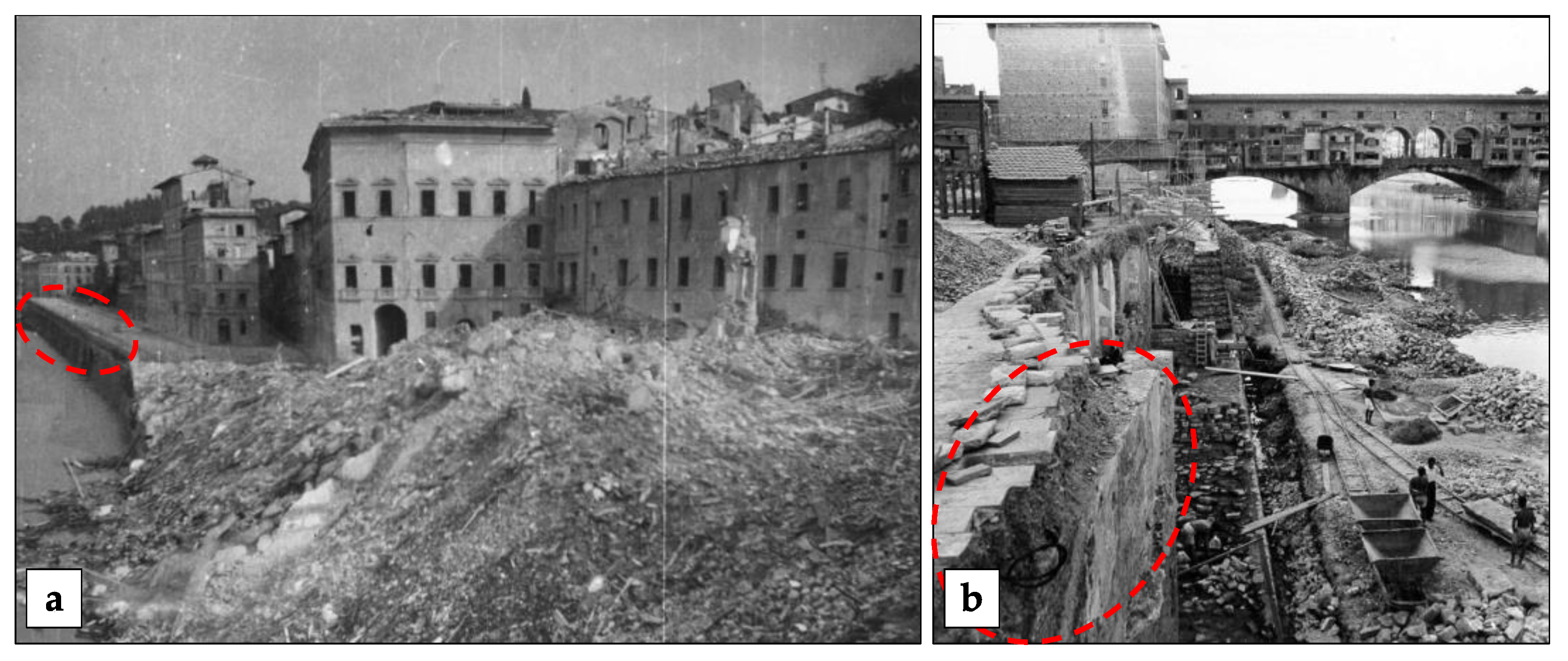
2. Historical and Area Framework

Lungarno Torrigiani is located on the hydrographical left side of the Arno river in Florence, between Ponte Vecchio and Ponte alle Grazie (Figure 1a). The construction was started during the years 1854–1855 and continued with all the work for the new urban infrastructures (Piano Particolareggiato) until 1872 [14].
The general working program was developed by Luigi Del Sarto, while the architect and director of the works was Giuseppe Poggi. The plan involved the complete transformation of the city; it was divided into ten parts, six on the hydrographical right side and four on the hydrographical left side of the Arno river [15].
In terms of preventing the damage of collapse and flooding, Giuseppe Poggi designed the new Arno riverbanks. In particular, Lungarno Torrigiani was built expanding the left bank of the Arno river and demolishing some facade building for their alignment; in fact, the new Lungarno cut through the land from Ponte Vecchio to Ponte alle Grazie (Figure 1b).
Figure 1. In the red square the study area (a) today, (b) in 1594 by Stefano Buonsignori [16]. (adapted with permission from https://commons.wikimedia.org/wiki/File:Mappa_del_buonsignori,_dettaglio_03.JPG#/media/File:Pianta_del_buonsignori,_1594,_00.JPG, 2013, Sailko, accessed on 28 March 2023).
Heritage 06 00203 g001
According to the Poggi project, by the Budini and Gattai construction company (active in many construction sites in Florence [17]), the retaining wall of Lungarno Torrigiani riverbank is composed of a massive scarp with four rows of wood piles driven 1.20 m under the medium level of the river (Figure 2). The masonry is made up of a vertical foundation wall of 0.75 m, a massive scarp wall of 7.17 m and a brick railing of 1.20 m high from the road surface complete the riverbank.
The wall is constructed with an external layer and an internal core using the rubble masonry building method. The former consists of a cortical wall constructed of various squared stones, quarried near Florence and therefore widely used in the city’s buildings (mainly Pietra Serena sandstone, and in other stretches of the Lungarno also with Pietraforte sandstone and Pietra Alberese marly limestone, as reported by the municipal historical archive of Florence). The latter consists of mortar made of coarse aggregate (mostly stone elements and, in some levels, also bricks) bound together by a binder filling the interior.
The behavior during the failure of the Lungarno Torrigiani highlighted an extremely compact, supportive, rigid wall system. In fact, there were three main breaks, corresponding to clear fractures, the central one in correspondence with the movement towards the river and two “lateral hinges”. This compactness is certainly due to the construction techniques of specialized workers, very active during the entire period from and after Florence as the Capital of Italy. According to this technique, all the elements of the masonry (stone blocks, fillings, binders and coatings) were carried out simultaneously.
Historical research shows that in 1944 during World War II, a section of Lungarno Torrigiani near the Ponte Vecchio was partially destroyed. The Nazi high command had ordered the German commander, Field Marshal Albert Keisselring, to blow up Florence’s bridges, but to save any he deemed “culturally significant”. During the operation called Feuerzauber or magic fire, only the Ponte Vecchio was saved, but not the buildings lining the approaching streets to the Ponte Vecchio, in order to block the way of the Allies. Figure 3a shows the photo after the Florence liberation, where only a part of the Lungarno Torrigiani close to the Ponte Vecchio was destroyed.
The reconstruction of this part of the Lungarno Torrigiani (which does not include the area object of this research, as visible in Figure 3a,b) was carried out considering the reconstruction plan “Città sul fiume, piano di ricostruzione della zona intorno al Ponte Vecchio” proposed by Edoardo Detti, Riccardo Gizdulich, Rolando Pagnini and Danilo Santi in 1947 [18,19]. Figure 3b shows reconstruction works throughout the post-war period.

3. Materials and Methods
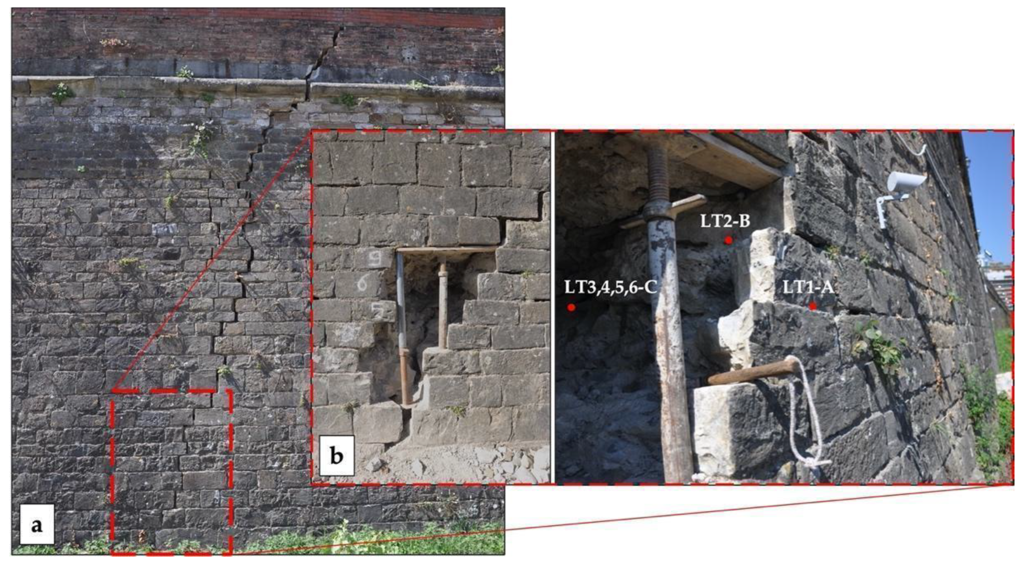
3.1. Sampling

The sampling was carried out from an area affected by fractures, cracks (Figure 4a) and detachments in the low part of the massive scarp wall, at the height of almost 1 m. The damaged section of the riverbank, where the sampling masonry was carried out, is located on a portion that remained unharmed from destruction during World War II. The samples shown in Figure 4b were collected from bedding mortars (LT1-A), jointing mortars (LT2-B) and core wall mortars (LT3, 4, 5, 6-C).
The mineralogical, petrographic and microchemical characterization was performed on 2 samples of mortar, belonging to bedding and jointing masonry, and 4 samples from core masonry. The physical and mechanical properties were determined on mortar sampling from the core masonry.

3.2. Mineralogical–Petrographic and Microchemical Analyses

The mineralogical–petrographic observations (OM) were performed with video camera (5 megapixels resolution), and analysis software AxioVision (V1), on the thin sections (30 µm) of the mortars [20]; this kind of analysis allows for highlighting the texture of the binder and the finer and medium coarse of the aggregate.
Mineralogical semi-quantitative characterizations were conducted with X-ray diffraction (XRPD) on bulk powder samples, using a diffractometer (Philips PW 1050/37 coupled with Philips X’Pert PRO for data acquisition and interpretation system); detection limit was 4% [21,22,23]. The operating conditions were: 40 kV-20 mA, Cu anode, graphite monochromator and 2°/min goniometry speed in 5–70° Ɵ range.
A SEM-EDS electronic microscope (ZEISS EVO MA 15) with W filament and an analytical system in the dispersion of energy EDS/SDD, Oxford Ultimax 40 (40 mm2 with resolution 127 eV @5.9 keV) was used to determine semi-quantitative microchemical and morphological characterizations.
The measurements were carried out on thin sections (after carbon-metallized pretreatment) in binder and lumps areas. The operating conditions were: 15 kV acceleration potential, 500 pA beam current, 9–8.5 mm working distance; 20 s live time as acquisition rate useful to archive at least 600,000 cts, on Co standard and process time 4 for point analyses; and 500 μs pixel dwell time for maps acquisition with 1024 × 768 pixel resolution.
The microanalysis was performed using Aztec 5.0 SP1 software employing the XPP matrix correction scheme developed by [24]. The process used purchased standard elements for calculations, allowing “standard-less” quantitative analysis. With numerous analyses of a Co metallic standard, the tracking of constant analytical conditions (i.e., filament emission) was recorded.

3.3. Physical and Mechanical Analysis

Samples of mortar of the core wall from the masonry embankment were used for the physical analysis to calculate the water absorption coefficients by capillarity and for total immersion, together with the open porosity and apparent density.
The water absorption by capillarity tests were performed based on the European standard [25] on four prismatic modules obtained by cutting the samples with dimensions of about 4 cm × 4 cm × 4 cm. The modules were dried in an oven at 60 °C until constant mass was reached. Then, each module was placed on a humid filter on footholds in the tank in contact with the water, allowing the samples to adsorb water by upward capillary forces. After a fixed time (5, 10, 20 30, 60, 90, 120,180, 240, 360, 1440, 2880 min) the samples were weighed, removing the water on the surface which was not absorbed using a wet cloth [26,27,28]. The test allowed us to estimate the water absorption by capillarity of the mortars.
The capillary water absorption coefficient C is calculated by linear regression, using at least five successive aligned points, considering the slope of the linear section of the curve obtained and plotting the mass difference versus the square root of time per area (A) (1).
C = ( M 2 M 1 ) A t f t i
where A equals the area of the sample, M1 and M2 are the sample mass at different time instant and ti and tf the initial and final time, respectively.
In order to better characterize the mortar physical properties, the samples were also tested for total water absorption, apparent density and open porosity. In addition, the mineralogical and petrographic analyses to identify mortar composition, structure, texture and pore system were important for testing the water absorption (described in Section 3.2).
The water absorption by total immersion tests provided the absorption of water during the time of totally immersed samples in water, based on the UNI EN 1097-6 [29]. The samples were obtained by cutting the four specimens used for capillarity absorption determination. Initially the specimens were dried in the oven until reaching a constant mass. Subsequently, they were saturated with water at a temperature of about 20 °C. The obtained results allowed us to determine the imbibition coefficient, according to Equation (2):
W = ( M s M d ) M d 100
where Ms is the sutured mass and Md the dry mass.
The total quantity of water absorbed is related to the total open porosity, after saturation, and the hydrostatic mass was determined according to the UNI EN 1936 [30] standard. Thanks to the hydrostatic balance of the Mettler Toledo XS 204, with a maximum weighing of 220 g and a resolution of 0.1 mg, hydrostatic mass, apparent density and open porosity were defined as:
ρ = M s M s M h ( ρ 0 ρ L ) + ρ L
P = M s M d M s M h 100
where Mh is the hydrostatic weight, ρ0 is the density of the auxiliary liquid and ρL is the air density.
In order to understand the mechanical behaviors of the samples, the ultrasonic velocity test was carried out on the same test samples (4 cm × 4 cm × 4 cm) for physical analysis. The cubic specimens, after the physical analysis, were again dried in a stove at a temperature of 60 °C until a constant weight was reached. In this way it was possible to compare all values and to correlate the results. The ultrasonic tests were performed through an IMG 5200 CSD ultrasonic instrument characterized by two 50 kHz transducers. The measurements were carried out in the direct transmission approach with two transducers placed on the opposite faces of samples in three dimensions. For each position, three measures were carried out in order to minimize errors; the result is the mean of nine measures for each sample. The calculated parameter is the velocity of the first ultrasonic wave able to travel through the material (Vp); based on its value it is possible to detect the occurrence of internal defects and inhomogeneities of the mortar itself.

4. Results and Discussion

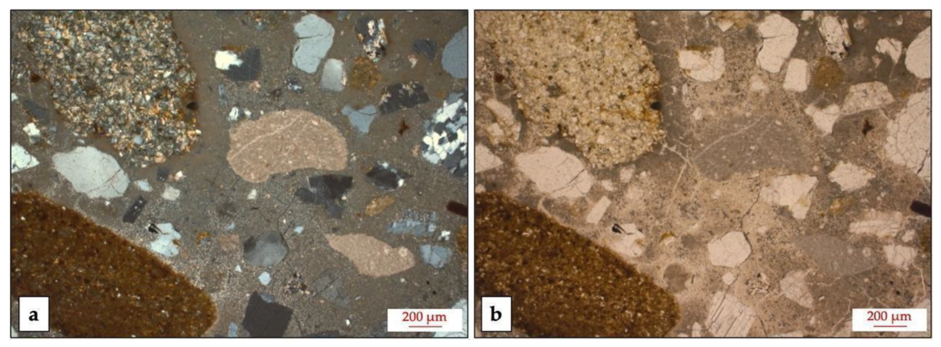
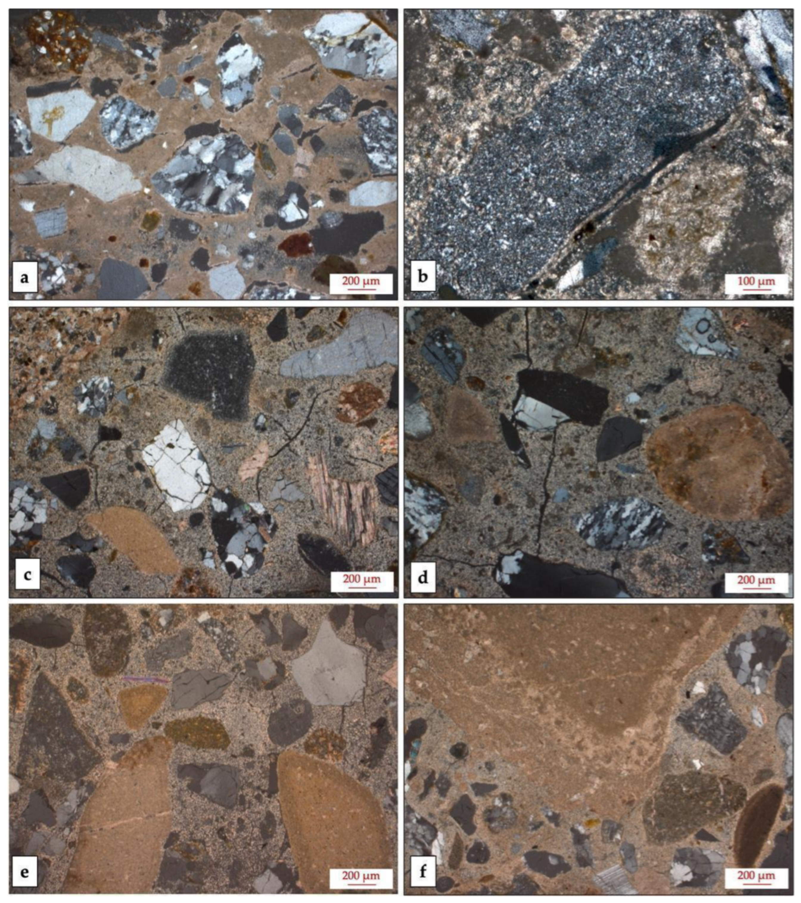
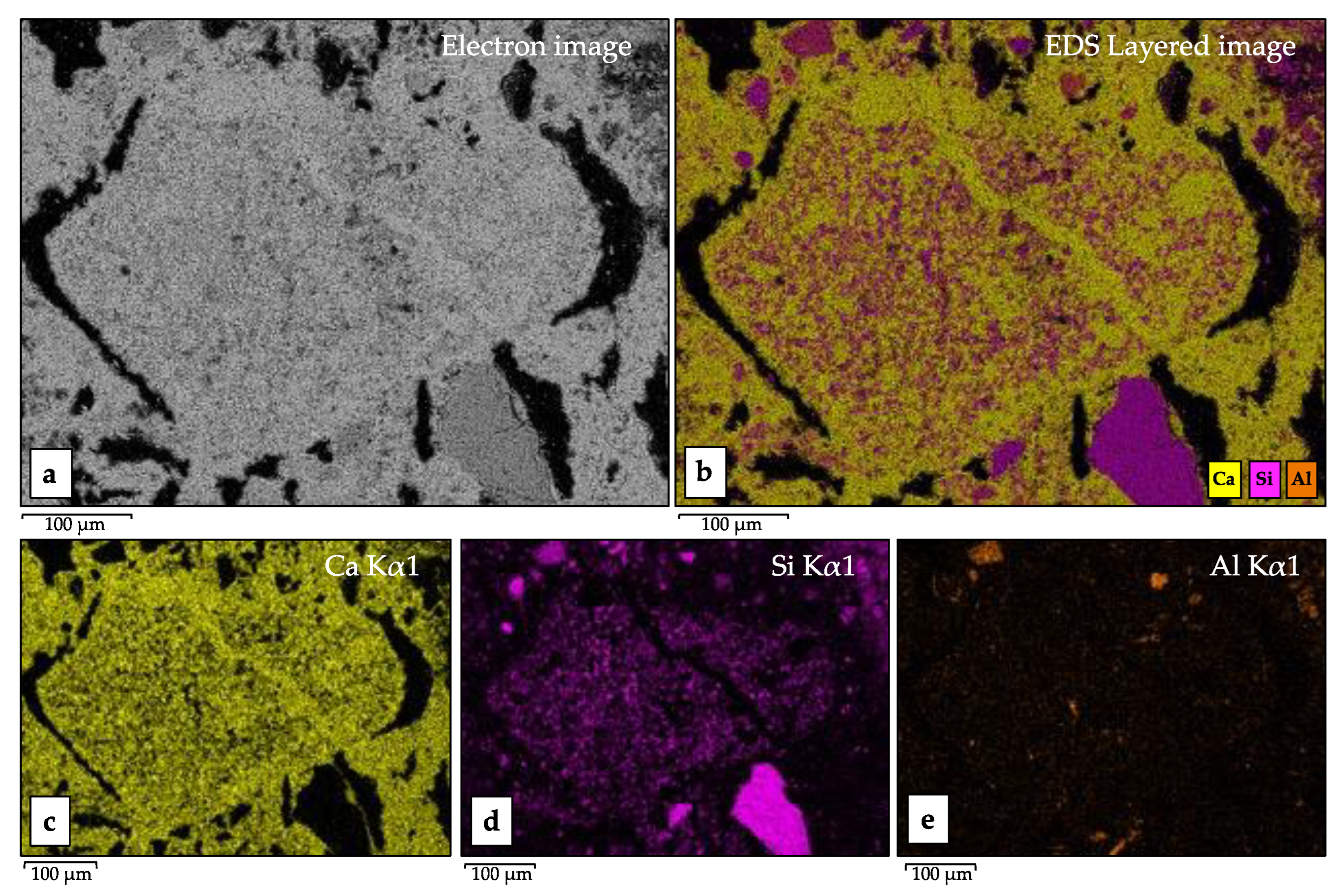
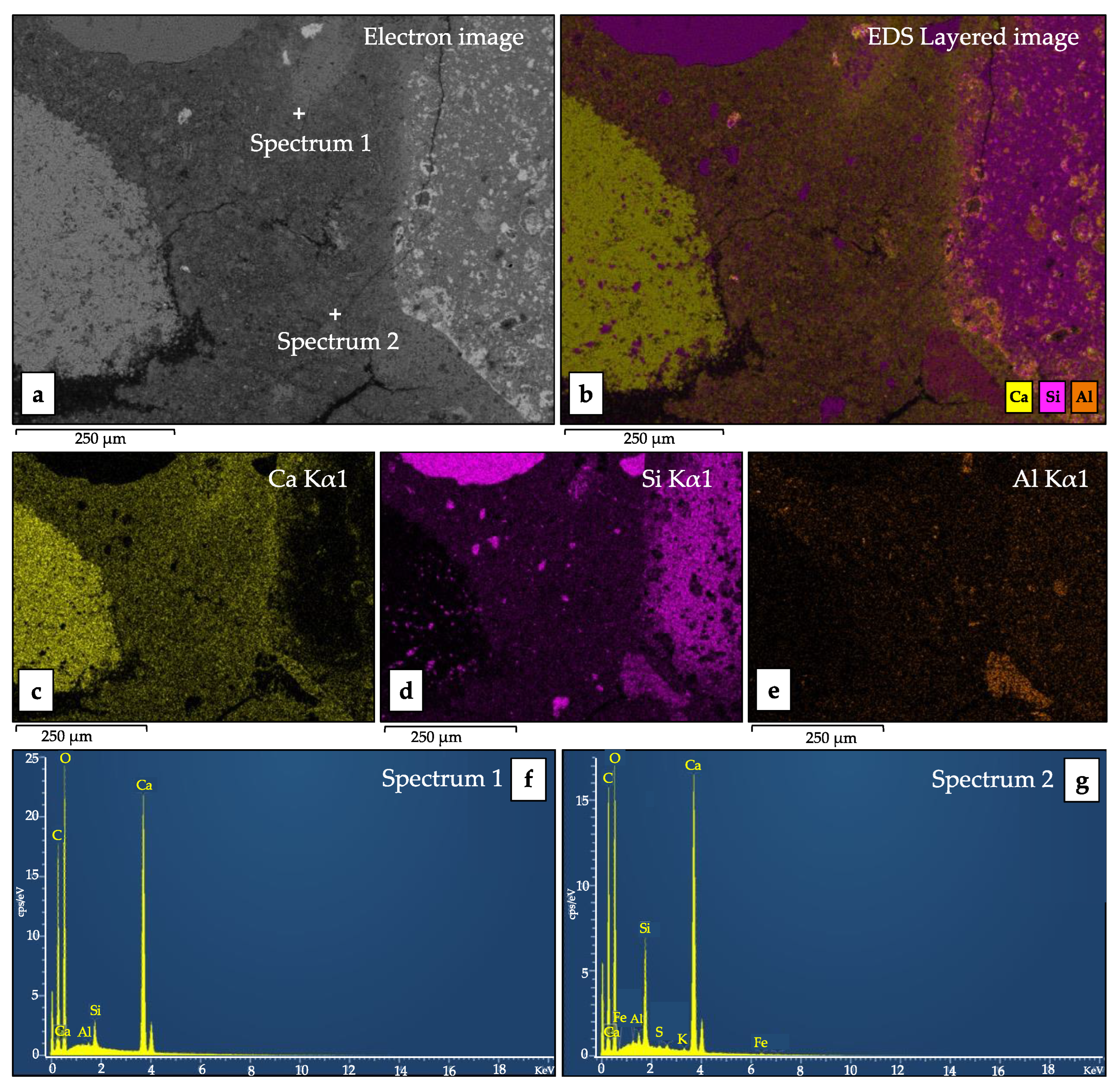
4.1. Mineralogical–Petrographic and Microchemical Data

The petrographic observations of the mortar of the bedding, of the jointing and of the core wall highlight similar characteristics, showing a binder made with an air hardening calcitic lime of light brown color, anisotropic and homogeneous appearance and with micritic and microsparitic texture; small dark impurities are widespread in the binder (Figure 5a,b). The aggregate is always well distributed, from sub-angular to sub-rounded in shape, with two-dimensional distribution (size from 200–300 µm to 500–600 µm); sometimes fragments of millimetric size are also present.
The composition mainly consists of sand in mono and polycrystalline quartz grains (Figure 6a) beyond calcite fragments, rare gypsum (Figure 6b), plagioclases and micas; besides sandstone, carbonate, marly limestones, mica schists, pelites and quartzitic rock fragments widespread in a binder showing small dark impurities (Figure 6c–e), rare cocciopesto is also present (Figure 6a). Lumps in the form of unmixed lime and of underburnt marly limestone remains are present, as well as a higher concentration of small dark impurities in the binder (Figure 6d–f). The macro porosity visible in thin sections is medium–low; there are also fractures and the binder/aggregate ratio is 1/3.
Pietra Alberese, a marly limestone from the Ligurian series (Monte Morello Formation, of Eocene age), is most likely the marly limestone found in the aggregate.
The locality near Florence where this marly formation exhibits the typical outcrop is where the term “Monte Morello Formation” originates. This stone was mainly employed to utilize the lime in the area from Florence to Pistoia.
The confirmation of the Pietra Alberese use in the past as a raw material for the production of lime is usually testified by “ghosts” of underburnt rock fragments in the historical mortars. Such inclusions show the same petrographic features of this marly limestone [31]. In the samples analyzed (Figure 6d–f) both fragments of Pietra Alberese limestone and lumps of the underburnt limestone are identified. This also justifies the presence, within the binder, of neoformation phases in the form of small dark impurities (Figure 5 and Figure 6). These consist of not-hydrated calcium silicates and aluminates as product of the reaction (in burning), between the calcium oxide coming from the dissociation of calcite and the amorphous silicate compound coming from the destruction of the clay minerals present in the marly limestone (Pietra Alberese) [32]. The use of Pietra Alberese in which a variable amount of clay minerals is present, from 7% to 26%, proves the presence of two varieties: sasso alberese with a lower content of clay minerals and lighter color and of sasso porcino with a higher content of clay minerals and darker color; both varieties can give rise to a partial hydraulicity in the mortar. The microscopic appearance of the Lungarno Torrigiani binders seem to confirm the use of sasso alberese [31].
The mineralogical semi-quantitative analyses on X-ray diffraction confirm the petrographic observations. The data in all samples show a prevalence of quartz and calcite, while plagioclases and k-feldspars (feldspars) with micas and clay minerals are in lower amounts (Table 1).
The SEM-EDS microchemical and morphological studies highlighted the characteristics of the binder and the lumps [33]. The presence of hydraulicity is often linked to the appearance of the binder and the lumps, showing small dark impurities that can be easily recognized by the polarized microscope, as underlined above. These impurities could be referred to as non-hydrated relics of belite (C2S). Therefore, SEM-EDS microchemical analyses of the unburnt lumps and binder areas were carried out (Figure 7 and Figure 8). The analysis on the unburnt lumps shows high values of Ca, and a variable amount of Si and Al, due to the presence of clay minerals in the original marly limestone (Figure 7). Such microchemical variability is reflected also on the composition of the binder, made by burning a marly limestone. Indeed, the binder shows a varying composition and a medium hydraulicity index about HI 0.20. The binder presents areas with Si and Al in higher amounts, due to the pollution given by the finest aggregate fraction (quartz and feldspars) widespread and areas with Ca prevailing due to a bad mixing. The punctual microchemical analysis in the binder sample LT6-C (core wall) confirms that Ca is 90% and Si 6% in spectrum 1, while in spectrum 2 Ca is prevailing (79%) with Si (14%) (Figure 8).
Nonetheless, it is possible to highlight that the core sample LT6-C has areas in which the binder has a higher content of Si and Al (Figure 8b–d), confirming the petrographic observations showing a higher concentration of small dark impurities in the binder.

4.2. Physical and Mechanical Data

Figure 9a shows the physical analysis results of the four core wall samples.
The average capillarity absorption coefficient (C) is about 27.75 g/m2s0.5, corresponding to an amount of water absorbed of about 15% typical of mortars. All the samples demonstrated a remarkably swift imbibition during the initial 60 min of the test, as the largest porosities became saturated through contact immediately [13,34,35,36]. In addition, IC, P and ρ showed typical values for the mortar [37]. There is a good correlation between the physical data and macroscopic observation. The mortar presented well sorted coarse aggregates from centimeter to millimeter size mixed with finer binder portions.
The ultrasonic velocity results are affected by the pores, fine portion/coarse aggregate ratio and aggregate dimensions. The presence of aggregates elevates velocity values, whereas a high porosity level in the sample results in lower ultrasonic velocities [38]. The pores in the fine portion of mortar and the cracks between the binder and aggregates cause discontinuity in the mortar, to which correspond both low ultrasonic velocities and low mechanical characteristics. The samples exhibited average Vp values of about 2300 m/s that include mortar and stone aggregates in good state of conservation, with quite good mechanical properties. The results of Vp for each examined sample show a good correlation with the macroscopic consideration on fine portion/coarse aggregate ratio, grading and content of aggregates (Figure 9b). In particular, sample LT3-C, characterized by the presence of coarse aggregate and less fine fraction, showed higher Vp values than sample LT6-C, which appeared more degraded with less presence of the coarse aggregate. In addition, if physical test results are also taken into account, sample LT3-C was characterized by lower porosity than the other three. Mortars with lower porosity levels show high density (ρ) and Vp values, whereas mortars with higher porosity levels and lower bulk density are expected to have lower ultrasonic propagation velocities.

5. Discussion about the Comparison between the Lungarno Torrigiani Mortars with Lungarno degli Acciaiuoli and Lungarno delle Grazie

It is interesting to compare the results obtained from analyzing the mortar in the inner part of the Lungarno Torrigiani rubble masonry with the information gathered in a study by Calandra et al. in 2022 [13]. The latter investigated the chemical, mineralogical–petrographic and physico-mechanical properties of core samples taken from the stonework of two other riverbanks in Florence (Lungarno degli Acciaiuoli and Lungarno delle Grazie).
All riverbanks of Florence were in fact expanded by Giuseppe Poggi over the course of the 1800s for the redevelopment of the city. In Lungarno degli Acciaiuoli and Lungarno delle Grazie, four typologies of mortar were identified; two ancient (named Type X and Type Y in [13]) and two modern mortars. Based on a macroscopic description, the mortar closer to Lungarno Torrigiani mortar is the one named Type Y [13], described as a historic mortar with centimeter-sized coarse aggregates. Such mortar corresponds to the deepest portion in the two riverbanks masonry stratigraphy. The microscopic characterization results, however, suggest that the fine portions of the two ancient mortars (Type Y and Type X) have the same composition and differ only by macroscopical aspects.
From the comparison between Lungarno degli Acciaiuoli, Lungarno delle Grazie and Lungarno Torrigiani petrographic observations, differences were observed, even though the raw material used to produce lime remained constant (Pietra Alberese). Lungarno degli Acciaiuoli and Lungarno delle Grazie samples showed a darker colored binder with heterogeneous appearance (areas with low birefringence were identified) and micritic/microsparitic texture. This is typical of mortars obtained from burning of Pietra Alberese with higher clay minerals (sasso porcino). On the contrary, the Lungarno Torrigiani mortars presented a lighter colored binder with micritic/microsparitic texture, but homogeneous appearance typical of mortars obtained from burning of Pietra Alberese with lower clay minerals amount (sasso alberese). The different binder characteristics of Lungarno degli Acciaiuoli and Lungarno delle Grazie may therefore be due to a higher hydraulicity (obtained burning sasso porcino) [31]. In addition, the endoscopic investigations of Lungarno degli Acciaiuoli and Lungarno delle Grazie have shown a storm drain running parallel to the Lungarni. Such a structure could allow more water into the masonry; this could change the optical features of the binder, making it darker.
Comparing the results of the physical analysis (Figure 10), it is possible to highlight that the mortars of the Lungarno Torrigiani have similar porosity and imbibition coefficient values to the mortars of type Y from Lungarno degli Acciaiuoli and Lungarno delle Grazie. While the capillarity absorption and the ultrasonic velocity are slightly lower, such distinction could be due to higher hydraulic behavior of Lungarno degli Acciaiuoli and Lungarno delle Grazie mortars, confirming the use of a different variety of Pietra Alberese with higher content of clay minerals.
In any case, the findings indicate that all riverbanks exhibit favorable mineralogical–petrographic and physico-mechanical properties. The mortars display both high compactness and cohesion levels.

6. Conclusions

In general terms, it can be assessed that the original mortar used in the Lungarno Torrigiani historical embankment wall has been created by burning a marly limestone (Pietra Alberese, probably variety sasso alberese), and is able to provide a partial hydraulicity to the mortars and give a good cohesion with coarse and fine aggregates utilized in the manufacturing. The partial hydraulicity is confirmed both by the presence of not-hydrated calcium silicates and aluminates, visible in small dark impurities widespread in the binder and by the results of the microchemical analysis highlighting binder areas with a medium hydraulicity index. It is interesting to underline that the petrographic and microchemical analyses carried out on the internal core show a greater thickening of dark small impurities and a higher amount of Si and Al in the binder, confirming a greater resistance of this part of the masonry. Therefore, the numerous lumps (both underburnt fragments of Pietra Alberese and of unmixed lime) present in the mixture prove a historical production technique of the mortars. The centimeter/millimeter-sized coarse aggregates are constituted mainly by sandstone and marly limestone stone fragments (most likely Pietra Serena, Pietraforte and Pietra Alberese of local origin), while the finer fraction is constituted mainly by quartzitic sand, also in this case from the Florentine area, probably the Arno valley. These aggregates are always well distributed. The macroporosity is medium–low; it is interesting to underline that the core samples (LT3, 4, 5, 6-C) show a lower porosity and appear more compact.
The mortars show good physical properties: low porosity (P = 24%) that ensure a low imbibition coefficient and low capillarity absorption coefficient (IC = 12.72% and C = 27.75 g/m2s0.5), with good density (ρ = 2.23 g/cm3) and good mechanical properties, in agreement with the characteristic described by [36]. A correlation between petrographic observation (macroporosity, type of binder, composition of aggregate, etc.) and physical and mechanical data has been observed, confirming the good quality of the mortars.
It is important to underline the excellent quality of the materials used and the type of traditional manufacturing, combined with the construction method used by the Budini and Gattai construction company. The rubble masonry, in which the wall is created with an outer layer and an internal core built gradually at the same time (the first consisting in a cortical wall made with squared stone (sandstone) and the inner filled with mortar) allowed it to avoid the catastrophic event [17]. Indeed, during the failure event of 25 May 2016, the Lungarno Torrigiani riverbank did not collapse into the Arno river.

Author Contributions

Conceptualization E.P., S.C., T.S., I.C. and C.A.G.; methodology, T.S., E.P. and S.C.; investigation, S.C., E.P. and T.S.; data curation, S.C., E.P. and T.S.; writing—original draft preparation, S.C., E.P., I.C. and T.S.; writing—review and editing, S.C., E.P., I.C. and T.S.; supervision, C.A.G. All authors have read and agreed to the published version of the manuscript.

Funding

This research received no external funding.

Data Availability Statement

Not applicable.

Acknowledgments

The authors are grateful to MEMA Centro di Servizi di Microscopia Elettronica e Microanalisi (DST-UNIFI) for the technical support with the SEM-EDS analysis.

Conflicts of Interest

The authors declare no conflict of interest.

References

  1. Morelli, S.; Segoni, S.; Manzo, G.; Ermini, L.; Catani, F. Urban planning, flood risk and public policy: The case of the Arno River, Firenze, Italy. Appl. Geogr. 2012, 34, 205–218. [Google Scholar] [CrossRef]
  2. Morelli, S.; Pazzi, V.; Tofani, V.; Raspini, F.; Bianchini, S.; Casagli, N. Reconstruction of the slope instability conditions before the 2016 failure in an Urbanized District of Florence (Italy), a UNESCO world heritage site. In Understanding and Reducing Landslide Disaster Risk; Sendai Landslide Partnerships (Kobe-City, Japan); Kyoto Landslide Commitment 5th: Kyoto, Japan, 2021; Volume 1, pp. 449–455. [Google Scholar]
  3. Morelli, S.; Battistini, A.; Catani, F. Rapid assessment of flood susceptibility in urbanized rivers using digital terrain data: Application to the Arno river case study (Firenze, northern Italy). Appl. Geogr. 2014, 54, 35–53. [Google Scholar] [CrossRef]
  4. Morelli, S.; Pazzi, V.; Tanteri, L.; Nocentini, M.; Lombardi, L.; Gigli, G.; Casagli, N. Characterization and geotechnical investigations of a riverbank failure in Florence, Italy, UNESCO World Heritage Site. J. Geotech. Geoenviron. Eng. 2020, 146, 05020009. [Google Scholar] [CrossRef]
  5. Dapporto, S.; Rinaldi, M.; Casagli, N.; Vannocci, P. Mechanisms of riverbank failure along the Arno River, Central Italy. Earth Surf. Process. Landf. 2003, 28, 1303–1323. [Google Scholar] [CrossRef]
  6. Asioli, C.; Bertero, A.; Cribari, F.; Agostini, C.; Chiarugi, M.; Galli, O.; Tognotti, M.; Spinelli, P.; Aiello, E.; Micheloni, M. Intervento di messa in sicurezza in somma urgenza del tratto interessato da dissesto sul Lungarno Torrigiani a Firenze: Progetto ed esecuzione delle opere di consolidamento, conservazione e ripristino del muro spondale dislocate. In Proceedings of the XXVI Convegno Nazionale di Geotecnica, Rome, Italy, 20–22 June 2017; Associazione Geotecnica Italiana (AGI): Rome, Italy, 2017. [Google Scholar]
  7. Pazzi, V.; Lotti, A.; Chiara, P.; Lombardi, L.; Nocentini, M.; Casagli, N. Monitoring of the vibration induced on the Arno masonry embankment wall by the conservation works after the May 25, 2016 riverbank landslide. Geoenviron. Disasters 2017, 4, 6. [Google Scholar] [CrossRef]
  8. Ponce-Antón, G.; Arizzi, A.; Cultrone, G.; Zuluaga, M.C.; Ortega, L.A.; Agirre Mauleon, J. Investigating the manufacturing technology and durability of lime mortars from Amaiur Castle (Navarre, Spain): A chemical–mineralogical and physical study. Constr. Build. Mater. 2021, 299, 123975. [Google Scholar] [CrossRef]
  9. Sardella, A.; Canevarolo, S.; Marrocchino, E.; Tittarelli, F.; Bonazza, A. Investigation of Building Materials Belonging to the Ruins of the Tsogt Palace in Mongolia. Heritage 2021, 4, 2494–2514. [Google Scholar] [CrossRef]
  10. Columbu, S.; Lisci, C.; Sitzia, F.; Lorenzetti, G.; Lezzerini, M.; Pagnotta, S.; Raneri, S.; Legnaioli, S.; Palleschi, V.; Gallello, G.; et al. Mineralogical, petrographic and physical-mechanical study of Roman construction materials from the Maritime Theatre of Hadrian’s Villa (Rome, Italy). Measurement 2018, 127, 264–276. [Google Scholar] [CrossRef]
  11. Franzoni, E.; Santandrea, M.; Gentilini, C.; Fregni, A.; Carloni, C. The role of mortar matrix in the bond behavior and salt crystallization resistance of FRCM applied to masonry. Constr. Build. Mater. 2019, 209, 592–605. [Google Scholar] [CrossRef]
  12. Haneefa, K.M.; Rani, S.D.; Ramasamy, R.; Santhanam, M. Microstructure and geochemistry of lime plaster mortar from a heritage structure. Constr. Build. Mater. 2019, 225, 538–554. [Google Scholar] [CrossRef]
  13. Calandra, S.; Salvatici, T.; Centauro, I.; Cantisani, E.; Garzonio, C.A. The Mortars of Florence Riverbanks: Raw Materials and Technologies of Lungarni Historical Masonry. Appl. Sci. 2022, 12, 5200. [Google Scholar] [CrossRef]
  14. Cresti, C.; Zangheri, L. Architetti e Ingegneri nella Toscana dell’800; UNEDIT: Florence, Italy, 1978. [Google Scholar]
  15. Poggi, G. Sui Lavori per L’ingrandimento di Firenze. Relazione di G.P. (1864–1877); Barbera, G., Ed.; Fiorentinagas—Giunti: Florence, Italy, 1882. [Google Scholar]
  16. Del Badia, I. Pianta topografica della città di Firenze di don Stefano Bonsignori dell’anno 1584. In Proceedings of the Atti del III Congresso Geografico Italiano, Florence, Italy, 12–17 April 1898; pp. 570–577. [Google Scholar]
  17. Fei, S.; Spini, G. Nascita e Sviluppo di Firenze Città Borghese; Editrice: Alberobello, Italy, 1971. [Google Scholar]
  18. Fantozzi Micali, O. Piani di Ricostruzione e Città Storiche 1945–1955; Alinea: Florence, Italy, 1998. [Google Scholar]
  19. Gabellini, P.; Ragghianti, R. Edoardo Detti 1913–1984. In Le Sculture di Paolo Borghi Omaggio agli Urbanisti del Novecento; Ministero dei Lavori Pubblici: Rome, Italy, 2001. [Google Scholar]
  20. UNI EN 12407; Natural Stone Test Methods—Petrographic Examination. Ente Nazionale Italiano di Normazione: Milan, Italy, 2007.
  21. UNI EN 13925-1; Non-Destructive Testing—X-Ray Diffraction from Polycrystalline and Amorphous Material—Part 1: General Principles. Ente Nazionale Italiano di Normazione: Milan, Italy, 2006.
  22. UNI EN 13925-2; Non-Destructive Testing—X-Ray Diffraction from Polycrystalline and Amorphous Materials—Part 2: Procedures. Ente Nazionale Italiano di Normazione: Milan, Italy, 2006.
  23. UNI-EN 13925-3; Non-Destructive Testing—X-Ray Diffraction from Polycrystalline and Amorphous Materials—Part 3: Instruments. Ente Nazionale Italiano di Normazione: Milan, Italy, 2006.
  24. Pouchou, J.L.; Pichoir, F. Quantitative Analysis of Homogeneous or Stratified Microvolumes Applying the Model “PAP”. In Electron Probe Quantitation; Springer: Boston, MA, USA, 1991; pp. 31–75. [Google Scholar] [CrossRef]
  25. UNI EN 1015-18:2002; Methods of Test for Mortar for Masonry—Part 18: Determination of Water Absorption Coefficient due to Capillary Action of Hardened Mortar. Ente Nazionale Italiano di Normazione: Milan, Italy, 2002.
  26. Martys, N.S.; Ferraris, C.F. Capillarity transport in mortars and concrete. Cem. Concr. Res. 1997, 27, 747–760. [Google Scholar] [CrossRef]
  27. Lanzón, M.; García-Ruiz, P.A. Evaluation of capillary water absorption in rendering mortars made with powdered waterproofing additives. Constr. Build. Mater. 2009, 23, 3287–3291. [Google Scholar] [CrossRef]
  28. Cunha, S.; Aguiar, J.; Ferreira, V.; Tadeu, A. Mortars based in different binders with incorporation of phase-change materials: Physical and mechanical properties. Eur. J. Environ. Civ. Eng. 2015, 19, 1216–1233. [Google Scholar] [CrossRef]
  29. UNI-EN 1097-6; Tests for Mechanical and Physical Properties of Aggregates—Part 6: Determination of Particle Density and Water Absorption. Ente Nazionale Italiano di Normazione: Milan, Italy, 2013.
  30. UNI EN 1936; Natural Stones Test Methods: Determination of Real Density and Apparent Density and of Total and Open Porosity. Ente Nazionale Italiano di Normazione: Milan, Italy, 2007.
  31. Fratini, F.; Cantisani, E.; Pecchioni, E.; Pandeli, E.; Vettori, S. Pietra Alberese: Building Material and Stone for Lime in the Florentine Territory (Tuscany, Italy). Heritage 2020, 3, 1520–1538. [Google Scholar] [CrossRef]
  32. Pecchioni, E.; Fratini, F.; Cantisani, E. Atlas of the Ancient Mortars in Thin Section under Optical Microscope, 2nd ed.; Nardini: Florence, Italy, 2020; p. 78. [Google Scholar]
  33. Cantisani, E.; Fratini, F.; Pecchioni, E. Optical and electronic microscope for minero-petrographic and microchemical studies of lime binders of ancient mortars. Minerals 2022, 12, 41. [Google Scholar] [CrossRef]
  34. Veiga, R.; Velosa, A.; Magalhaes, A. Experimental applications of mortars with pozzolanic additions: Characterization and performance evaluation. Constr. Build. Mater. 2009, 23, 318–327. [Google Scholar] [CrossRef]
  35. Aragon, G.; Aragon, A.; Santamaria, A.; Esteban, A.; Fiol, F. Physical and mechanical characterization of a commercial rendering mortar using destructive and non-destructive techniques. Constr. Build. Mater. 2019, 224, 835–849. [Google Scholar] [CrossRef]
  36. Cantisani, E.; Calandra, S.; Barone, S.; Caciagli, S.; Fedi, M.; Garzonio, C.A.; Vettori, S. The mortars of Giotto’s Bell Tower (Florence, Italy): Raw materials and technologies. Constr. Build. Mater. 2021, 267, 120801. [Google Scholar] [CrossRef]
  37. Moropoulou, A.; Bakolas, A.; Anagnostopoulou, S. Composite materials in ancient structures. Cem. Concr. Compos. 2005, 27, 295–300. [Google Scholar] [CrossRef]
  38. Arizzi, A.; Cultrone, G. The influence of aggregate texture, morphology and grading on the carbonation of non-hydraulic (aerial) lime-based mortars. Q. J. Eng. Geol. Hydrogeol. 2013, 46, 507–520. [Google Scholar] [CrossRef]
Figure 2. Construction techniques of the Lungarno Torrigiani riverbank (modified from original drawings preserved in the municipal historical archive of Florence).
Heritage 06 00203 g002
Figure 3. (a) Image of Lungarno Torrigiani close to the Ponte Vecchio after the liberation in the 1944: the condition of the riverbank; (b) the reconstruction of the Lungarno close to the Ponte Vecchio, in 1947 (photo Fondo Berti, ISRT). In red are highlighted the walls of Lungarno Torrigiani that remained unharmed.
Heritage 06 00203 g003
Figure 4. Study area and sampling position of Lungarno Torrigiani riverbank: (a) damaged area by embankment failures, on which an assay was carried out to study the masonry and perform sampling; (b) the assay and position of mortars sampling from bedding, jointing and from the core of masonry.
Heritage 06 00203 g004
Figure 5. (a) Image under PLM, xpl: mortar with an air hardening calcitic lime and aggregate characterized of different rock fragments (sandstone, marly limestone, pelite, quartzite); (b) image under PLM, ppl: small dark impurities are widespread in the binder of the mortar.
Heritage 06 00203 g005
Figure 6. Images under PLM, xpl; (a) LT1-A, mortar sample with an air hardening calcitic lime and aggregate constituted in prevalence of polycrystalline quartz, calcite and quartzitic fragments; (b) LT2-B, mortar showing a fragment of gypsum; (c) LT3-C, mortar with characteristic aggregate of two different sizes and quartzitic and calcitic composition; (d) LT4-C, mortar with quartzite aggregate, a lump in form of an underburnt marly limestone remains and small dark impurities in the binder; (e) LT5-C, mortar with prevalence of marly limestone fragments; (f) LT6-C, mortar showing mainly a lump in form of an underburnt marly limestone remains.
Heritage 06 00203 g006
Figure 7. (a) BS image of a detail of a binder portion and of the unburnt limestone (sample LT1-A) in which areas with different gray tones can be observed; (b) SEM-EDS map layered of the previous area; (c) SEM-EDS map of Ca; (d) SEM-EDS map of Si; (e) SEM-EDS map of Al.
Heritage 06 00203 g007
Figure 8. (a) BS image of a detail of the binder portion (sample LT6-C) in which areas with different gray tones can be observed and punctual microchemical analysis of the sample; (b) SEM-EDS layered image of the previous area; (c) SEM-EDS map of Ca; (d) SEM-EDS map of Si; (e) SEM-EDS map of Al; (f,g) EDS spectra of punctual analysis of binder.
Heritage 06 00203 g008
Figure 9. Results of physical and mechanical analyses. (a) The values reported are capillary water absorption coefficient (C), open porosity (P, or porosity accessible to the water), total imbibition coefficient (IC) and density (ρ). (b) The Vp mean value and macroscopic images of each examined sample.
Heritage 06 00203 g009
Figure 10. Comparison between physical and mechanical data of Lungarno Torrigiani mortar and Type Y and Type X of Lungarno degli Acciaiuoli and Lungarno delle Grazie mortars. (a) P (%) vs. IC (%) and (b) C (g/m2s0.5) vs. Vp (m/s).
Heritage 06 00203 g010
Table 1. XRPD results of the analysis of Lungarno Torrigiani mortar samples.
SampleQuartzCalciteFeldsparsMicasClay Minerals
LT1-Axxxxxxtrtr
LT2-Bxxxxxxtrtr
LT3-Cxxxxxtrtr
LT4-Cxxxxxxtrtr
LT5-Cxxxxxxtrtr
LT6-Cxxxxxtrtrtr
Semi-quantitative amount xxx = high amount; xx = medium amount; x = low amount; tr = in traces.
Disclaimer/Publisher’s Note: The statements, opinions and data contained in all publications are solely those of the individual author(s) and contributor(s) and not of MDPI and/or the editor(s). MDPI and/or the editor(s) disclaim responsibility for any injury to people or property resulting from any ideas, methods, instructions or products referred to in the content.

