
Free Vibration Characteristics of Multi-Material Lattice Structures


1
General Electric Aviation, Gebze 41400, Kocaeli, Turkey
2
Faculty of Power and Aeronautical Engineering, Warsaw Institute of Technology, 00-661 Warsaw, Poland
3
Department of Mechanical Engineering, Imperial College London, London SW7 2AZ, UK
*
Authors to whom correspondence should be addressed.
Vibration 2023, 6(1), 82-101; https://doi.org/10.3390/vibration6010007
Submission received: 19 November 2022
/
Revised: 28 December 2022
/
Accepted: 12 January 2023
/
Published: 16 January 2023
(This article belongs to the Special Issue Feature Papers in Vibration)
Abstract
:This paper presents a modal analysis of honeycomb and re-entrant lattice structures to understand the change in natural frequencies when multi-material configuration is implemented. For this purpose, parallel nylon ligaments within re-entrant and honeycomb lattice structures are replaced with chopped and continuous carbon fibre to constitute multi-material lattice configurations. For each set, the first five natural frequencies were compared using detailed finite element models. For each configuration, three different boundary conditions were considered, which are free–free and clamping at the two sides that are parallel and perpendicular to the vertical parts of the structure. The comparison of the natural frequencies was based on mode-shape matching using modal assurance criteria to identify the correct modes of different configurations. The results showed that the natural frequency of the multi-material configurations increases from 4% to 18% depending on the configuration and material.
1. Introduction
Lattice structures are formed by interconnected and repeated unit cells built by open pores and non-stochastic orientation [1]. Lattice structures have distinct characteristics and are used in engineering. Especially in the automotive and aerospace industry [2], manufacturers use lattice structures to reach the goals of reduction at the amount of material, time, and energy in production and, most importantly, strengthening their product while decreasing its weight [3]. Although different types of conventional manufacturing techniques have been considered for producing lattice structures, they are not optimal for production since they require complex tools with precise process control and need more steps to assemble or bond to create intended lattice structures [4]. Parts with grids can be manufactured easily from discrete unit cells with the help of additive manufacturing processes [5].
Lattice structures have several different types. One popular type is the regular honeycomb lattice structure, which is formed by uniformly distributed double-layered hexagonal cells [6]. These lattice structures provide high strength with low weight and less material and they are generally used as a form of sandwich structure [7]. Due to their favourable qualities in several applications, honeycomb lattice structures have a wide range of use in electronic equipment [8], air vehicles [9], and highway bridge structures [10]. In addition to regular lattice structures, such as the regular honeycomb, some cellular materials come forward due to their unusual behaviours, namely meta-materials. Meta-materials originate from materials that are used in electromagnetism with unconventional mechanical properties [11]. In addition, meta-materials are known as material systems whose physical properties can be tailored for the needed purpose and performance [12,13]. A common meta-material is the auxetic materials that are known for their specific property of having a negative Poisson’s ratio (NPR). Opposing conventional materials, they laterally expand under tensile loads and shrink when a compressive load is applied. This unique behaviour provides the utilization of auxetic lattice structures in different applications for energy absorption and vibration damping.
Normally, honeycomb lattice structures are composed of two chevrons and two parallel ligaments. The ligaments that create the chevron provide elasticity to the cell, while the parallel ligaments yield stability to the lattice structure. The cell direction in which auxeticity is experienced is called in-plane direction and the direction that is perpendicular to the in-plane direction is named the out-of-plane direction. In the same way, re-entrant lattice structures are constituted by flipping the chevrons or, in other words, increasing the angle of the intersection that creates the chevron by more than 90. Similarly, a regular honeycomb lattice structure is obtained if the angle is less than 90. Thus, in opposition to the regular honeycomb lattice structures, the re-entrant lattice structures could expand or contract in the transverse direction when stretched or compressed [14]. Due to that, improved performances could be recorded in re-entrant lattice structures, such as enhanced shear modulus [15] and energy absorption in comparison to a regular honeycomb lattice structure [16,17].
Meta-material lattices possess unique vibration characteristics, including band gaps and directional wave propagation characteristics that outshine them in control and operate wave propagation and vibration suppression [18]. Researchers have worked on multi-material lattice structures, the vibration of 3D printed standard samples, and lattice structures via different methodologies. Whitten et al. investigated the lattice vibration frequencies of MgSi by using elastic constants retrieved from the longitudinal and transverse sound velocity measurements of MgSi from 80 to 300 K using a resonance technique [19]. Csertil and Tichy studied the classical lattice dynamics of honeycomb lattices with harmonic approximation [20]. Hori and Asahi showed that the transfer matrix method by Kerner is an effective method to calculate the eigenfrequency distribution of some types of lattice structures, including disordered, by applying the transfer matrix method to an atomic linear chain vibration problem [21]. Li and Yan researched if an innovative two-dimensional (2D) hybrid auxetic elastic metamaterial could broaden the bandgap of vibration isolation [22]. The research conducted by Kaplunov et al. aims to find the lowest vibration modes of multi-component rods and cylinders with changing high-contrast material properties of the components [23]. Xin et al. proposed re-entrant and star-shaped hybrid honeycomb meta-materials (RSHHM) in which the elastic rubber-coated mass inclusions were added to create the low-frequency band gaps [24]. Tateno and Nishie investigated the natural frequency of a multi-material additive manufactured object experimentally [25]. Monkova et al. examined the vibration damping characteristics of 3D printed Acrylonitrile Butadiene Styrene (ABS) samples under harmonic excitation at three placed inertial masses [26]. Hou et al. worked on mechanical properties of sandwich composites with 3D printed auxetic and non-auxetic lattice cores under low-velocity impact and found that the re-entrant lattice structure panel is good at robustness and durability but does not perform well at energy absorption capacity [27]. However, there is no research exploring the effect of multi-material implementation on the vibration behaviour of lattice structures.
The topology parameters of lattice structures directly affect the mechanical properties and, by means of these parameters, lattice structures are tailored for fulfilling the needed properties. However, topology parameters are not only the main driver for changing the properties but also for the constituent material influences the mechanical properties. Especially, the utilization of a multi-material approach provides optimization of the lattice structure in accordance with the design requirements. For example, carbon-fibre-reinforced lattice structures are exploited in the parts of lattice cell structures in which high buckling loads are needed. The improvements in additive manufacturing create an opportunity to produce multi-material lattice structures and fibre replacement is also possible within limited directions. The knowledge of re-entrant and honeycomb lattice structures has been improved and the cell geometry can be optimized topologically for specific applications to date. However, what is not known and what is limited is how a specific material or materials will function when used in part of the cell structure, especially for continuous or chopped fibre replacement in some parts. Further research is necessary to understand what multi-material configuration can be utilized in a specific part of the cell to optimize the cellular structure’s structural efficiency for its desired application. In this study, an original contribution was made to understand the free vibration characteristics of the honeycomb and re-entrant lattice structures when the multi-material configurations are utilized. The multi-material configurations were achieved by the substitution of material of parallel ligaments converted into continuous (CFRN) or chopped carbon-fibre composite (Onyx). The effects of this configuration on the natural frequencies were investigated by comparing the correlated mode shapes of the lattice structures.
2. Method
This section explains the methods used to obtain the free vibration characteristics of multi-material lattice structures.
2.1. Lattice Topology
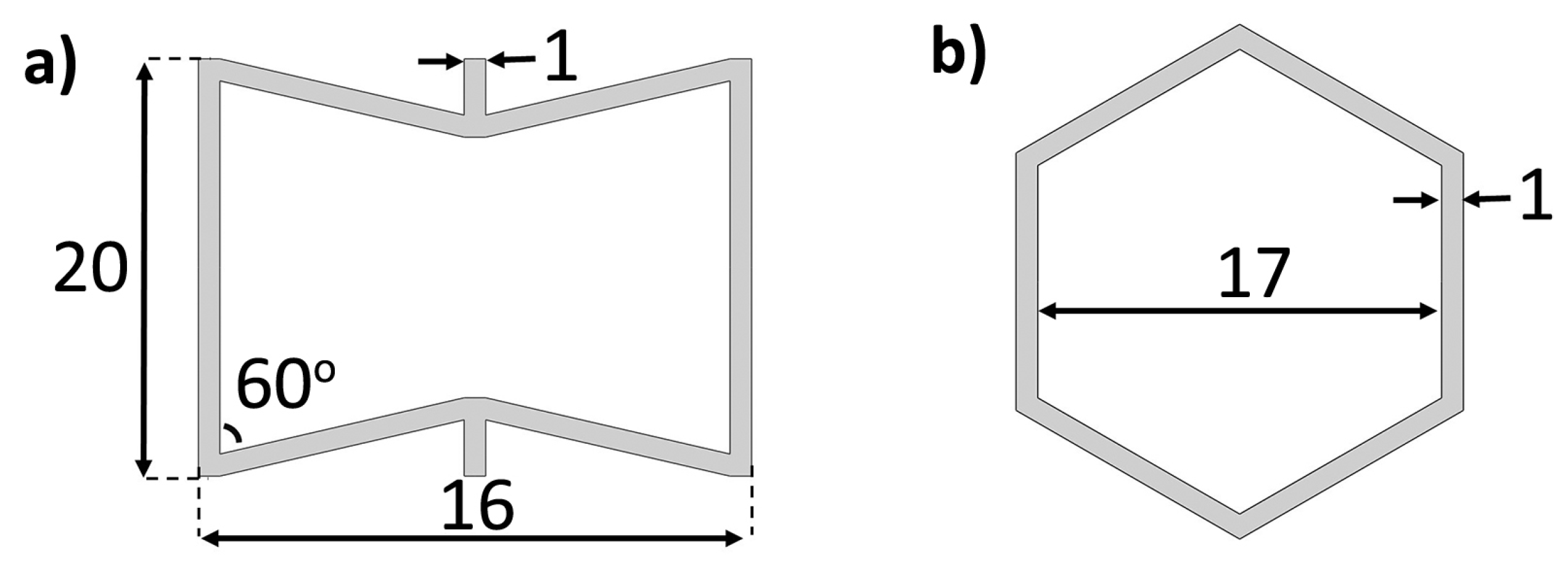
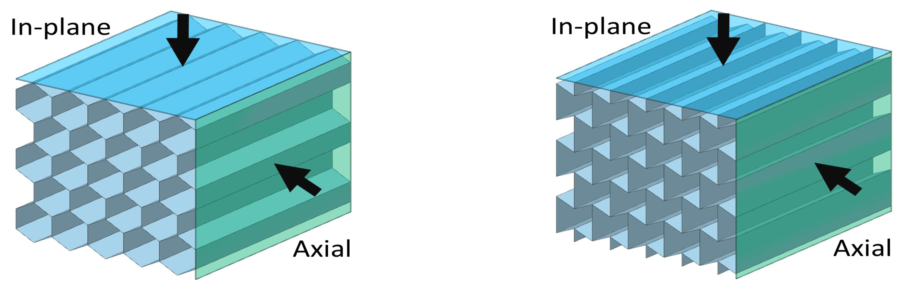
To construct the honeycomb and re-entrant lattice structures, typical lattice unit topology has been selected as in Figure 1. The lattice structures are formed from unit cells as 5 × 5. To create a comparable set that would exhibit similar overall geometries, the topology parameters of re-entrant and honeycomb lattice structures’ unit cells are specified. The thickness of ligaments for both lattice structures is decided considering the availability of additive manufacturing techniques and 1 mm is selected as the thickness value. Due to the topology of re-entrant and honeycomb lattice structures, they have two deformation axes in the lateral orientations called in-plane and axial, as shown in Figure 2.
2.2. Multi-Material Lattice Structure
Through the improvements in additive manufacturing technologies, the multi-material production approach is enabled within different 3D printing technologies. One of the well-known and widespread technologies is fused deposition technology (FDM) due to its inexpensive installation, consumables, and spare parts. In FDM technology, a thermoplastic filament is fed and pushed through a nozzle by a mechanic feeder and this filament is heated to its melting point and then extruded through a nozzle, layer by layer, to create a three-dimensional intended component [28,29]. Thanks to improvements in AM technology, FDM printers allow the printing of more than one material during the printing of a component by changing the feeding material or using a dual extruder. For durable and high-strength production, particles such as chopped carbon fibres can be added to the thermoplastic filament, called Onyx material. In the Onyx material, chopped carbon-fibre whiskers are mixed with melted nylon to form filament for FDM printers and FDM printers produce parts from Onyx material with the below-mentioned procedure. Alternatively, continuous fibres can be deposited from one of the nozzles and matrix material can be deposited around the continuous fibres from the other nozzle. However, in this production method, it is not possible to deposit continuous fibres arbitrarily and it is only allowed to replace fibres in the parallel direction to the building plate. This is the main reason why chevrons are selected as nylon and parallel ligaments are chosen as continuous carbon-fibre-reinforced nylon and chopped carbon-fibre-reinforced nylon in this study.
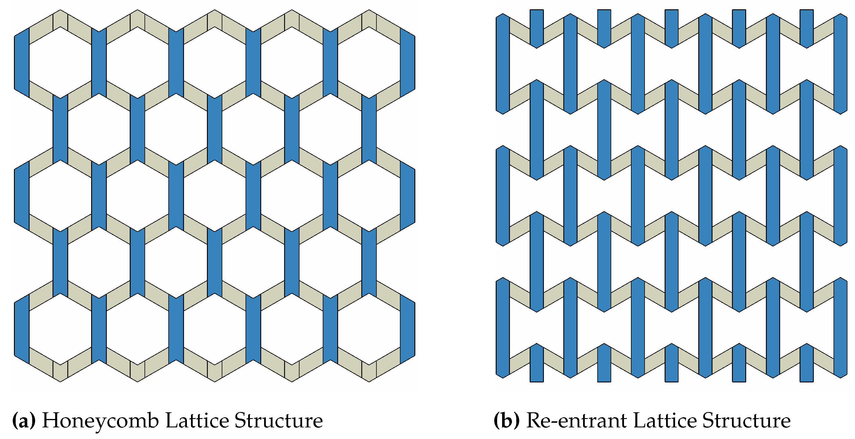
Parallel ligaments of nylon honeycomb and re-entrant lattice structures are substituted for composite and onyx materials as can be seen in Figure 3, indicated as the blue colour. The thickness is kept the same as the nylon components at the composite and onyx since the study aims to observe the vibration characteristics differentiating in both in-plane and out-of-plane directions related to the multi-material approach. Material properties are presented in Table 1. In the study of Gunaydin et al. [30] and Zhou et al. [31], the FEM simulation results of the regular honeycomb and re-entrant lattice structures produced from nylon and multi-material configuration using composite and onyx materials were validated with the experimental data that show the cohesion between the onyx material and carbon fibres’ cohesion with nylon does not affect the results considerably in the elastic region.
2.3. Finite Element Model
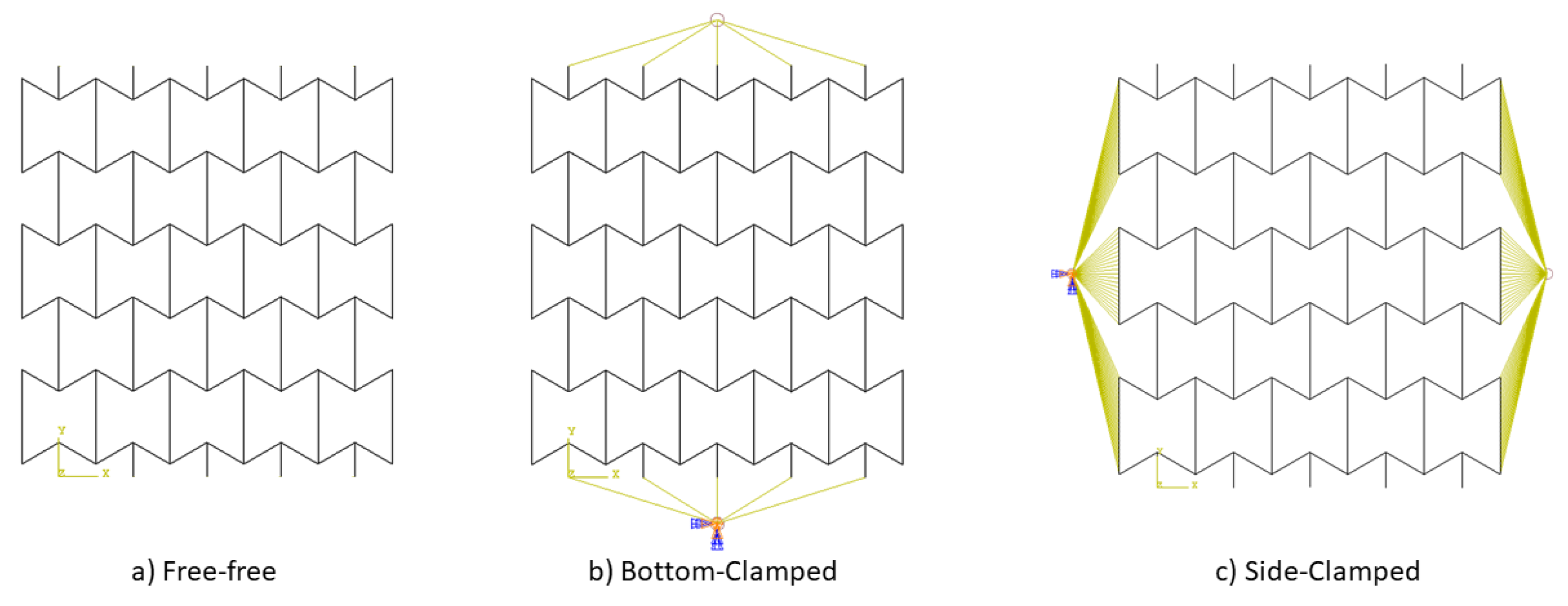
The finite element models (FEM) were created by using Abaqus CAE. The models are analysed for free vibration characteristics. Natural frequencies and the corresponding mode shapes were obtained from the modal analysis. For both honeycomb and re-entrant lattice structures, three boundary conditions were considered, as presented in Figure 4. The first boundary condition is the free–free boundary condition, which means that the lattice structure is free to move at its boundaries. The free–free boundary condition is typically used when a lattice structure supports are an order of magnitude or more softer than the lattice structure itself. The second boundary condition is referred to as bottom-clamped, in which the lattice structure is clamped on its edges. The third one is side-clamped, which refers to the fixed lattice structure on one side with flat surfaces.
2.4. Mesh Convergence
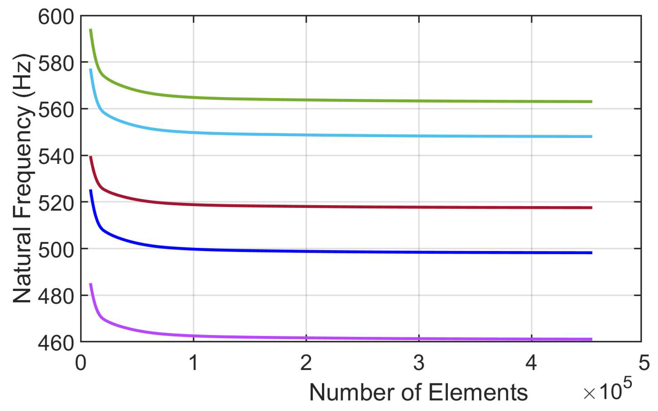
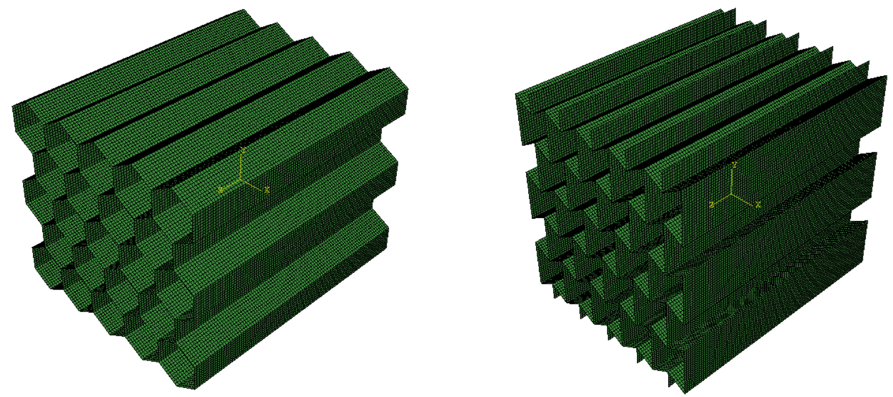
Both honeycomb and re-entrant lattice structures were discretized by quadrilateral elements since the walls are typically thin in lattice structures. To validate the conformance of element size selection for numerical analysis, a series of simulations were conducted to determine the efficient mesh size by compromising the computational cost and accuracy. The first mesh size was selected as 3 mm in order to obtain rough mesh discretization and subsequent smaller sizes were applied and the first five eigenvalues were plotted in Figure 5. The results show that the use of the 1 mm mesh size is the convergence starting point as represented with approximately 100,000 elements. Thus, a 1 mm mesh size (Figure 6) was implemented in all the FEM simulations. The total numbers of nodes and elements were reported in Table 2.
2.5. Mode Correlation
To see changes in natural frequencies of similar mode shapes, the Modal Assurance Criteria (MAC) [32] were applied. MAC are the tool that compares eigenvectors and provides a result from 0 to 1 to show how the eigenvectors of two different models are related, which is stated as:
and are the eigenvector matrices corresponding to two different sets of modal analysis. Being close to unity indicates that the two modes are almost identical and the similarity reduces for lower values of MAC. The MAC analysis was conducted by using MATLAB R2020a using the mode shapes extracted from Abaqus CAE.
3. Results
This section presents results obtained from the FE analysis described in the previous section. By changing the material of the vertical parts of the nylon honeycomb and nylon re-entrant lattice structures to composite and onyx (Figure 3), the multi-material regular and NPR honeycomb structures were obtained. The effect of this change on natural frequencies and modal shapes is observed by comparing the natural frequencies matched with a high MAC correlation. First, the honeycomb was presented for the three boundary conditions, which was followed by the re-entrant.
3.1. Honeycomb Lattice Structure
3.1.1. Honeycomb Lattice Structure: Free–Free
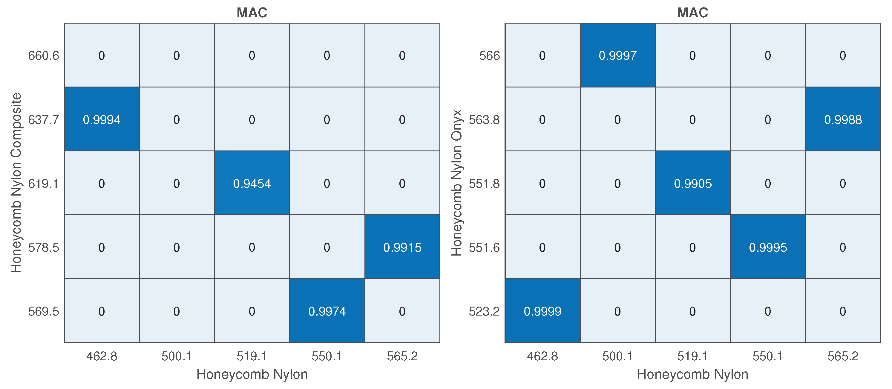
The modal analysis results of the honeycomb lattice structure that is bottom-clamped were obtained and matched to the nylon structure’s natural frequencies as shown in Figure 7. As can be seen in Figure 7, a satisfactory MAC correlation was obtained. The matched natural frequencies were compared in Table 3. The addition of composite and onyx increased the natural frequencies of similar mode shapes. However, the changes in natural frequencies are different such that adding a composite increased the natural frequencies more than adding onyx. Furthermore, the second mode of nylon did not match with any of the first five modes of the nylon composite. The mode shapes corresponding to the three bottom-clamped honeycomb configurations were presented in Table 4.
3.1.2. Honeycomb Lattice Structure: Bottom-Clamped
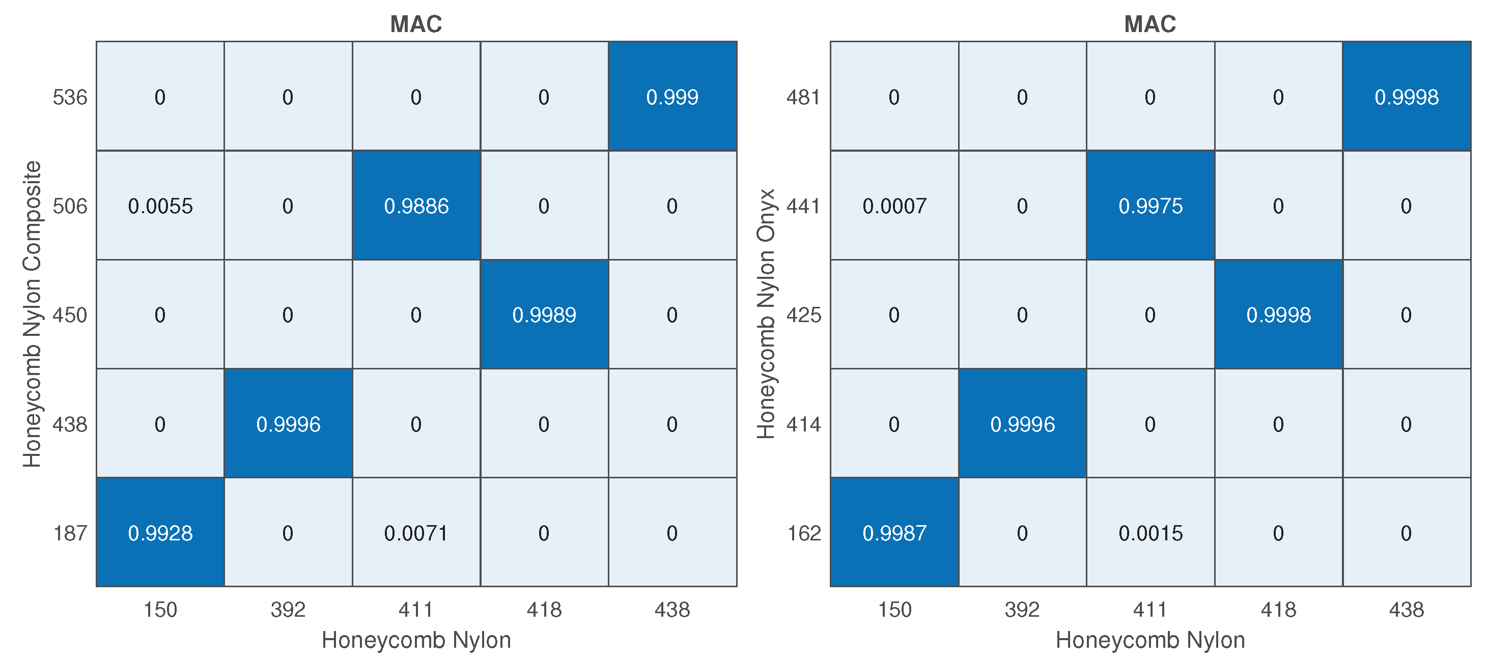
The modal analysis results of the honeycomb lattice structure that is bottom-clamped were obtained and matched to the nylon structure’s natural frequencies as shown in Figure 8. As can be seen in Figure 8, a satisfactory MAC correlation was obtained. The matched natural frequencies were compared in Table 5. The addition of composite and onyx increased the natural frequencies of similar mode shapes. However, the changes at the natural frequencies are different such that adding composite increased the natural frequencies more than adding onyx. The mode shapes corresponding to the three bottom-clamped honeycomb lattice structure configurations were presented in Table 6.
3.1.3. Honeycomb Lattice Structure: Side-Clamped
The same procedure was repeated for the side-clamped boundary conditions and the matched modes were obtained in Figure 9; 18% and 7% average changes were observed for the side-clamped case for nylon–composite and nylon–onyx configurations, respectively, which was reported in Table 7. The mode shapes corresponding to the three bottom-clamped honeycomb lattice structure configurations were presented in Table 8.
3.2. Re-Entrant Lattice Structure
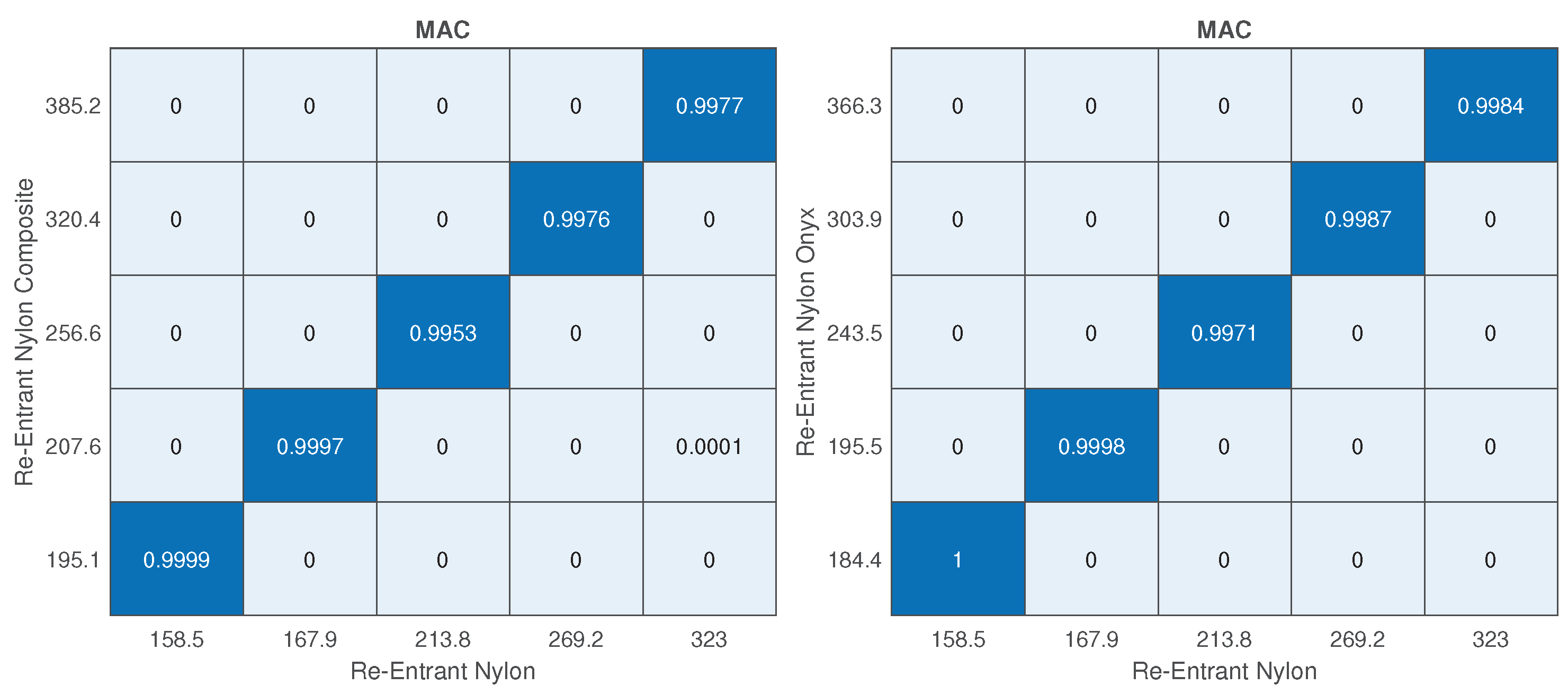
3.2.1. Re-Entrant Lattice Structure: Free–Free
The modal analysis results of the re-entrant lattice structure that is bottom-clamped were obtained and matched to the nylon structure’s natural frequencies as shown in Figure 10. As can be seen in Figure 10, a satisfactory MAC correlation was obtained. The matched natural frequencies were compared in Table 9. The addition of composite and onyx increased the natural frequencies of similar mode shapes. However, the change in natural frequencies is different such that adding composite increased the natural frequencies more than adding onyx. The mode shapes corresponding to the three bottom-clamped re-entrant lattice structure configurations were presented in Table 10.
3.2.2. Re-Entrant Lattice Structure: Bottom-Clamped
The modal analysis results of the re-entrant lattice structure that is bottom-clamped were obtained and matched to the nylon structure’s natural frequencies as shown in Figure 11. As can be seen in Figure 11, a satisfactory MAC correlation was obtained. The matched natural frequencies were compared in Table 11. The addition of composite and onyx increased the natural frequencies of similar mode shapes. However, the change in natural frequencies was different because adding composite increased the natural frequencies more than adding onyx. The mode shapes corresponding to the three bottom-clamped re-entrant lattice structure configurations were presented in Table 12.
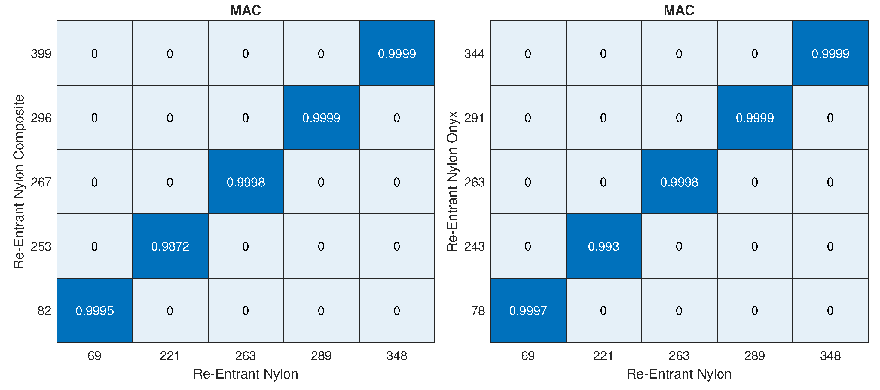
3.2.3. Re-Entrant Lattice Structure: Side-Clamped
The same procedure was repeated for the side-clamped boundary conditions and the matched modes were obtained using MAC in Figure 12. Similar results were obtained in the side-clamped case with a smaller increase in the natural frequencies, which was reported in Table 13. The mode shapes corresponding to the three bottom-clamped honeycomb lattice structure configurations were presented in Table 14.
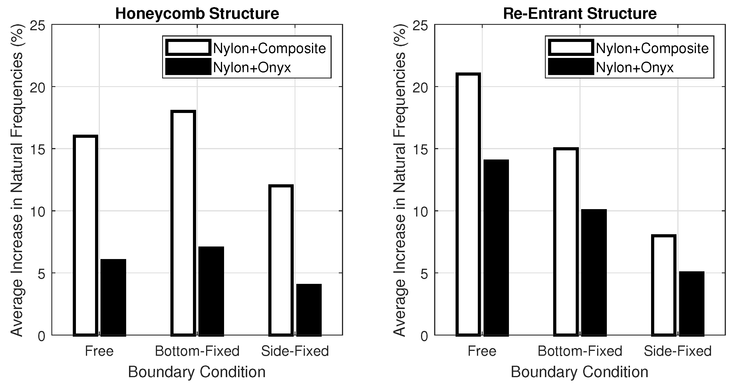
4. Conclusions
In this study, modal analyses of multi-material honeycomb and re-entrant lattice structures have been conducted by using Abaqus CAE. By applying modal assurance criterion (MAC), the changes in frequencies of MAC-correlated mode shapes are reported. The detailed results can be summarized in Figure 13, which shows the average increase in the natural frequencies when the vertical parts of a nylon auxetic lattice structure are replaced by composite or onyx. Based on the detailed simulations and the summarized results, the following observations could be made:
- Most of the natural frequencies of correlated mode shapes increased due to reinforcing the lattice structure with composite or onyx.
- Satisfactory MAC correlations were achieved for almost all cases, suggesting that adding composite or onyx does not affect the mode shapes.
- Clamping from the sharp edges (bottom-clamped) caused a bigger increase in natural frequencies as compared to fixing the material on the flat surfaces (side-clamped). This is due to the application of composite and onyx in the vertical direction.
- Adding composite led to a higher increase in natural frequencies as compared to using Onyx, which was expected due to the difference between their elastic moduli.
- The largest increase occurred for the lower natural frequencies suggesting that the higher modes benefit less from the addition of a higher-strength material. This could be explained by the fact that the inertial forces dominate as the frequency increases.
- It is expected that natural frequencies will increase when some part of a structure is replaced by a higher-strength and close-density material. However, the results showed that it is not always possible to state this, since natural frequencies remained constant or increased very slightly for some modes.
Author Contributions
Conceptualization, K.G. and A.T.; methodology, K.G. and A.T.; software, K.G. and A.T.; investigation, K.G. and A.Y.; resources, K.G. and A.T.; data curation, K.G. and A.Y.; writing—original draft preparation, K.G. and A.Y.; writing—review and editing, K.G., A.Y. and A.T.; visualization, K.G. and A.Y.; supervision, A.T. All authors have read and agreed to the published version of the manuscript.
Funding
This research received no external funding.
Institutional Review Board Statement
Not applicable.
Informed Consent Statement
Not applicable.
Data Availability Statement
Not applicable.
Conflicts of Interest
The authors declare no conflict of interest.
References
- Mahmoud, D.; Elbestawi, M.A. Lattice Structures and Functionally Graded Materials Applications in Additive Manufacturing of Orthopedic Implants: A Review. J. Manuf. Mater. Process. 2017, 1, 13. [Google Scholar] [CrossRef]
- Beyer, C.; Figueroa, D. Design and Analysis of Lattice Structures for Additive Manufacturing. J. Manuf. Sci. Eng. 2016, 138, 121014. [Google Scholar] [CrossRef]
- Helou, M.; Kara, S. Design, analysis and manufacturing of lattice structures: An overview. Int. J. Comput. Integr. Manuf. 2018, 31, 243–261. [Google Scholar] [CrossRef]
- Tao, W.; Leu, M.C. Design of lattice structure for additive manufacturing. In Proceedings of the 2016 International Symposium on Flexible Automation (ISFA), Cleveland, OH, USA, 1–3 August 2016; pp. 325–332. [Google Scholar]
- Kummert, C.; Schmid, H.J.; Risse, L.; Kullmer, G. Mechanical characterization and numerical modeling of laser-sintered TPE lattice structures. J. Mater. Res. 2021, 36, 3182–3193. [Google Scholar] [CrossRef]
- Zhang, Q.; Yang, X.; Li, P.; Huang, G.; Feng, S.; Shen, C.; Han, B.; Zhang, X.; Jin, F.; Xu, F.; et al. Bioinspired engineering of honeycomb structure–Using nature to inspire human innovation. Prog. Mater. Sci. 2015, 74, 332–400. [Google Scholar] [CrossRef]
- Thomas, T.; Tiwari, G. Crushing behavior of honeycomb structure: A review. Int. J. Crashworthiness 2019, 24, 555–579. [Google Scholar] [CrossRef]
- Dongmei, W.; Ziyou, B. Mechanical property of paper honeycomb structure under dynamic compression. Mater. Des. 2015, 77, 59–64. [Google Scholar] [CrossRef]
- Vos, R.; Barrett, R. Pressure adaptive honeycomb: A new adaptive structure for aerospace applications. In Sensors and Smart Structures Technologies for Civil, Mechanical, and Aerospace Systems 2010; Tomizuka, M., Ed.; International Society for Optics and Photonics; SPIE: Bellingham, WA, USA, 2010; Volume 7647, pp. 721–732. [Google Scholar] [CrossRef] [Green Version]
- Davalos, J.F.; Qiao, P.; Frank Xu, X.; Robinson, J.; Barth, K.E. Modeling and characterization of fiber-reinforced plastic honeycomb sandwich panels for highway bridge applications. Compos. Struct. 2001, 52, 441–452. [Google Scholar] [CrossRef]
- Zhao, W.; Zhu, J.; Liu, L.; Leng, J.; Liu, Y. Analysis of small-scale topology and macroscale mechanical properties of shape memory chiral-lattice metamaterials. Compos. Struct. 2021, 262, 113569. [Google Scholar] [CrossRef]
- Chen, Y.; Li, T.; Scarpa, F.; Wang, L. Lattice Metamaterials with Mechanically Tunable Poisson’s Ratio for Vibration Control. Phys. Rev. Appl. 2017, 7, 024012. [Google Scholar] [CrossRef] [Green Version]
- Garland, A.P.; White, B.C.; Jensen, S.C.; Boyce, B.L. Pragmatic generative optimization of novel structural lattice metamaterials with machine learning. Mater. Des. 2021, 203, 109632. [Google Scholar] [CrossRef]
- Wu, D.; Lee, H.P. Numerical and theoretical studies about in-plane impact properties of Semi-Reentrant structures. Meccanica 2021, 57, 313–336. [Google Scholar] [CrossRef]
- Huang, X.; Blackburn, S. Developing a new processing route to manufacture honeycomb ceramics with negative Poisson’s ratio. Key Eng. Mater. 2002, 206, 201–204. [Google Scholar] [CrossRef]
- Scarpa, F.; Ciffo, L.; Yates, J. Dynamic properties of high structural integrity auxetic open cell foam. Smart Mater. Struct. 2003, 13, 49. [Google Scholar] [CrossRef]
- Gunaydin, K.; Tamer, A.; Turkmen, H.S.; Sala, G.; Grande, A.M. Chiral-Lattice-Filled Composite Tubes under Uniaxial and Lateral Quasi-Static Load: Experimental Studies. Appl. Sci. 2021, 11, 3735. [Google Scholar] [CrossRef]
- Zhao, P.; Zhang, K.; Deng, Z. Elastic wave propagation in lattice metamaterials with Koch fractal. Acta Mech. Solida Sin. 2020, 33, 600–611. [Google Scholar] [CrossRef]
- Whitten, W.; Chung, P.; Danielson, G. Elastic constants and lattice vibration frequencies of Mg2Si. J. Phys. Chem. Solids 1965, 26, 49–56. [Google Scholar] [CrossRef]
- Cserti, J.; Tichy, G. A simple model for the vibrational modes in honeycomb lattices. Eur. J. Phys. 2004, 25, 723–736. [Google Scholar] [CrossRef] [Green Version]
- Hori, J.i.; Asahi, T. On the Vibration of Disordered Linear Lattice. Prog. Theor. Phys. 1957, 17, 523–542. [Google Scholar] [CrossRef]
- Li, Y.; Yan, G. Vibration characteristics of innovative reentrant-chiral elastic metamaterials. Eur. J. Mech. A Solids 2021, 90, 104350. [Google Scholar] [CrossRef]
- Kaplunov, J.; Prikazchikov, D.; Prikazchikova, L.; Sergushova, O. The lowest vibration spectra of multi-component structures with contrast material properties. J. Sound Vib. 2019, 445, 132–147. [Google Scholar] [CrossRef] [Green Version]
- Xin, Y.; Wang, H.; Wang, C.; Cheng, S.; Zhao, Q.; Sun, Y.; Gao, H.; Ren, F. Properties and tunability of band gaps in innovative reentrant and star-shaped hybrid honeycomb metamaterials. Results Phys. 2021, 24, 104024. [Google Scholar] [CrossRef]
- Tateno, T.; Nishie, S. Vibration Characteristics of Unit Cell Structures Fabricated by Multi-Material Additive Manufacturing. In Mechanics of Additive and Advanced Manufacturing; Wang, J., Antoun, B., Brown, E., Chen, W., Chasiotis, I., Huskins-Retzlaff, E., Kramer, S., Thakre, P.R., Eds.; Springer International Publishing: Cham, Switzerland, 2018; Volume 9, pp. 79–81. [Google Scholar]
- Monkova, K.; Vasina, M.; Zaludek, M.; Monka, P.P.; Tkac, J. Mechanical Vibration Damping and Compression Properties of a Lattice Structure. Materials 2021, 14, 1502. [Google Scholar] [CrossRef] [PubMed]
- Hou, S.; Li, T.; Jia, Z.; Wang, L. Mechanical properties of sandwich composites with 3d-printed auxetic and non-auxetic lattice cores under low velocity impact. Mater. Des. 2018, 160, 1305–1321. [Google Scholar] [CrossRef]
- Günaydın, K.; Türkmen, H.S. Common FDM 3D Printing Defects. In Proceedings of the International Congress on 3D Printing (Additive Manufacturing) Technologies and Digital Industry, Antalya, Turkey, 19–21 April 2018. [Google Scholar]
- Günaydın, K.; Eren, Z.; Kazancı, Z.; Scarpa, F.; Grande, A.M.; Türkmen, H.S. In-plane compression behavior of anti-tetrachiral and re-entrant lattices. Smart Mater. Struct. 2019, 28, 115028. [Google Scholar] [CrossRef]
- Günaydın, K.; Rea, C.; Kazancı, Z. Energy absorption enhancement of additively manufactured hexagonal and re-entrant (auxetic) lattice structures by using multi-material reinforcements. Addit. Manuf. 2022, 59, 103076. [Google Scholar] [CrossRef]
- Zhou, J.; Liu, H.; Dear, J.P.; Falzon, B.G.; Kazancı, Z. Comparison of different quasi-static loading conditions of additively manufactured composite hexagonal and auxetic cellular structures. Int. J. Mech. Sci. 2023, 244, 108054. [Google Scholar] [CrossRef]
- Pastor, M.; Binda, M.; Harčarik, T. Modal Assurance Criterion. Procedia Eng. 2012, 48, 543–548. [Google Scholar] [CrossRef]
Figure 1.
Unit cell dimension of (a) re-entrant and (b) regular honeycomb lattice structures.

Figure 2.
Loading directions of lattice structures: Honeycomb (left) and Re-entrant (right).

Figure 3.
Composite ligaments highlighted with blue color in otherwise nylon structures.

Figure 4.
Boundary conditions shown on the re-entrant lattice structure configuration: Bottom-Clamped (b) and Side-Clamped (c).
Figure 4.
Boundary conditions shown on the re-entrant lattice structure configuration: Bottom-Clamped (b) and Side-Clamped (c).

Figure 5.
Mesh convergence plot for the first five natural frequencies.

Figure 6.
Meshed models of honeycomb (left) and re-entrant lattice structures (right).

Figure 7.
MAC results of honeycomb lattice structure: Free–free.

Figure 8.
MAC results of honeycomb lattice structure: Bottom-clamped.

Figure 9.
MAC results of honeycomb lattice structure: Side-clamped.

Figure 10.
MAC analysis’ result of re-entrant lattice structure: Free–free.

Figure 11.
MAC analysis results for re-entrant lattice structure: Bottom-clamped.

Figure 12.
MAC analysis results for re-entrant lattice structure: Side-clamped.

Figure 13.
Average change in top five natural frequencies for honeycomb lattice structure and re-entrant lattice structures.
Figure 13.
Average change in top five natural frequencies for honeycomb lattice structure and re-entrant lattice structures.


Table 1.
Mechanical properties of nylon, continuous carbon-fibre-reinforced nylon, and chopped carbon-fibre-reinforced nylon.
Table 1.
Mechanical properties of nylon, continuous carbon-fibre-reinforced nylon, and chopped carbon-fibre-reinforced nylon.
| Tensile Modulus (GPa) | Tensile Stress (MPa) | Density (g/cm3) | |
|---|---|---|---|
| Nylon | 1.7 | 51 | 1.1 |
| Continuous Carbon | 3.2 | 210 | 1.1 |
| Chopped Carbon (Onyx) | 2.4 | 40 | 1.2 |
Table 2.
Mesh type, number of nodes, and number of elements for the finite element models.
| Honeycomb | Re-Entrant | |
|---|---|---|
| Mesh type | Quadrilateral | Quadrilateral |
| Number of nodes | 86,658 | 118,776 |
| Number of elements | 88,000 | 119,800 |
Table 3.
First five natural frequencies of the honeycomb lattice structure in the free–free boundary condition and the paired modes when the material of vertical parts of honeycomb lattice structure changed to composite or onyx.
Table 3.
First five natural frequencies of the honeycomb lattice structure in the free–free boundary condition and the paired modes when the material of vertical parts of honeycomb lattice structure changed to composite or onyx.
| Nylon | Nylon Composite | Change (%) | Nylon Onyx | Change (%) |
|---|---|---|---|---|
| 462.8 | 637.7 | +38 | 523.2 | +13 |
| 500.1 | 566 | +13 | ||
| 519.1 | 619.1 | +19 | 551.8 | +6 |
| 550.1 | 569.5 | +4 | 551.6 | +0.3 |
| 565.2 | 578.5 | +2 | 563.8 | −0.2 |
| Average | +16 | Average | +6 |
Table 4.
First five paired mode shapes of Honeycomb Lattice Structure free–free.
| Nylon | Nylon + Composite | Nylon + Onyx |
|---|---|---|
 |  |  |
| 462.84 Hz | 637.66 Hz | 523.18 Hz |
 |  | |
| 500.06 Hz | 566.01 Hz | |
 |  |  |
| 519.09 Hz | 619.05 Hz | 551.80 Hz |
 |  |  |
| 550.10 Hz | 569.50 Hz | 551.61 Hz |
 |  |  |
| 565.18 Hz | 578.46 Hz | 563.77 Hz |
Table 5.
First five natural frequencies of honeycomb lattice structure in the bottom-clamped boundary condition and the paired modes when the material of vertical parts of honeycomb lattice structure changed to composite or onyx.
Table 5.
First five natural frequencies of honeycomb lattice structure in the bottom-clamped boundary condition and the paired modes when the material of vertical parts of honeycomb lattice structure changed to composite or onyx.
| Nylon | Nylon Composite | Change (%) | Nylon Onyx | Change (%) |
|---|---|---|---|---|
| 150 | 187 | +25 | 162 | +8 |
| 392 | 438 | +12 | 414 | +6 |
| 411 | 506 | +23 | 441 | +7 |
| 418 | 450 | +8 | 425 | +2 |
| 438 | 536 | +23 | 481 | +10 |
| Average | +18 | Average | +7 |
Table 6.
First five paired mode shapes of Honeycomb Lattice Structure with bottom clamped.
| Nylon | Nylon + Composite | Nylon + Onyx |
|---|---|---|
 |  |  |
| 149.59 Hz | 186.63 Hz | 161.98 Hz |
 |  |  |
| 392.02 Hz | 438.32 Hz | 414.38 Hz |
 |  |  |
| 411.43 Hz | 506.35 Hz | 441.19 Hz |
 |  |  |
| 417.90 Hz | 449.60 Hz | 424.90 Hz |
 |  |  |
| 437.53 Hz | 536.24 Hz | 481.40 Hz |
Table 7.
First five natural frequencies of honeycomb lattice structure in the side-clamped boundary condition and the paired modes when the material of vertical parts of honeycomb lattice structure changed to composite or onyx.
Table 7.
First five natural frequencies of honeycomb lattice structure in the side-clamped boundary condition and the paired modes when the material of vertical parts of honeycomb lattice structure changed to composite or onyx.
| Nylon | Nylon Composite | Change (%) | Nylon Onyx | Change (%) |
|---|---|---|---|---|
| 151 | 180 | +19 | 161 | +7 |
| 344 | 362 | +5 | 350 | +1 |
| 408 | 421 | +3 | 408 | 0 |
| 418 | 490 | +17 | 442 | +6 |
| 424 | 496 | +17 | 446 | +5 |
| Average | +12 | Average | +4 |
Table 8.
First five paired mode shapes of Honeycomb Lattice Structure with right and left sides clamped.
Table 8.
First five paired mode shapes of Honeycomb Lattice Structure with right and left sides clamped.
| Nylon | Nylon + Composite | Nylon + Onyx |
|---|---|---|
 |  |  |
| 150.58 Hz | 179.53 Hz | 160.79 Hz |
 |  |  |
| 344.48 Hz | 361.79 Hz | 349.60 Hz |
 |  |  |
| 408.24 Hz | 420.89 Hz | 408.26 Hz |
 |  |  |
| 417.97 Hz | 489.64 Hz | 442.00 Hz |
 |  |  |
| 423.56 Hz | 495.79 Hz | 445.70 Hz |
Table 9.
First five natural frequencies of re-entrant lattice structure in the free–free boundary condition and the paired modes when the material of vertical parts of honeycomb lattice structure changed to composite or onyx.
Table 9.
First five natural frequencies of re-entrant lattice structure in the free–free boundary condition and the paired modes when the material of vertical parts of honeycomb lattice structure changed to composite or onyx.
| Nylon | Nylon Composite | Change (%) | Nylon Onyx | Change (%) |
|---|---|---|---|---|
| 158.5 | 195.1 | +23 | 184.4 | +16 |
| 167.9 | 207.6 | +24 | 195.5 | +16 |
| 213.8 | 256.6 | +20 | 243.5 | +14 |
| 269.2 | 320.4 | +19 | 303.9 | +13 |
| 323 | 385.2 | +19 | 366.3 | +13 |
| Average | +21 | Average | +14 |
Table 10.
First five paired mode shapes of Re-entrant Lattice Structure: Free–free.
| Nylon | Nylon + Composite | Nylon + Onyx |
|---|---|---|
 |  |  |
| 158.53 Hz | 195.14 Hz | 184.37 Hz |
 |  |  |
| 167.87 Hz | 207.64 Hz | 195.48 Hz |
 |  |  |
| 213.81 Hz | 256.59 Hz | 243.46 Hz |
 |  |  |
| 269.16 Hz | 320.39 Hz | 303.94 Hz |
 |  |  |
| 322.96 Hz | 385.22 Hz | 366.35 Hz |
Table 11.
First five natural frequencies of re-entrant lattice structure in the bottom-clamped boundary condition and the paired modes when the material of vertical parts of honeycomb lattice structure changed to composite or onyx.
Table 11.
First five natural frequencies of re-entrant lattice structure in the bottom-clamped boundary condition and the paired modes when the material of vertical parts of honeycomb lattice structure changed to composite or onyx.
| Nylon | Nylon Composite | Change (%) | Nylon Onyx | Change (%) |
|---|---|---|---|---|
| 57 | 69 | +21 | 66 | 14 |
| 172 | 203 | +18 | 194 | +13 |
| 201 | 227 | +13 | 219 | +9 |
| 216 | 233 | +8 | 227 | +5 |
| 286 | 329 | +15 | 315 | +10 |
| Average | +15 | Average | +10 |
Table 12.
First five paired mode shapes of Re-entrant Lattice Structure with top and bottom clamped.
Table 12.
First five paired mode shapes of Re-entrant Lattice Structure with top and bottom clamped.
| Nylon | Nylon + Composite | Nylon + Onyx |
|---|---|---|
 |  |  |
| 57.44 Hz | 69.30 Hz | 65.63 Hz |
 |  |  |
| 171.78 Hz | 203.34 Hz | 193.54 Hz |
 |  |  |
| 200.73 Hz | 226.62 Hz | 219.31 Hz |
 |  |  |
| 216.10 Hz | 232.92 Hz | 227.39 Hz |
 |  |  |
| 286.16 Hz | 328.86 Hz | 314.93 Hz |
Table 13.
First five natural frequencies of re-entrant lattice structure in the bottom-clamped boundary condition and the paired modes when the material of vertical parts of re-entrant lattice structure changed to composite or onyx.
Table 13.
First five natural frequencies of re-entrant lattice structure in the bottom-clamped boundary condition and the paired modes when the material of vertical parts of re-entrant lattice structure changed to composite or onyx.
| Nylon | Nylon Composite | Change (%) | Nylon Onyx | Change (%) |
|---|---|---|---|---|
| 69 | 82 | +19 | 78 | +13 |
| 221 | 253 | +14 | 243 | +10 |
| 268 | 267 | +2 | 263 | 0 |
| 3289 | 296 | +3 | 291 | +1 |
| 348 | 349 | 0 | 344 | -1 |
| Average | +8 | Average | +5 |
Table 14.
First five paired mode shapes of Re-entrant Lattice Structure with right and left sides clamped.
Table 14.
First five paired mode shapes of Re-entrant Lattice Structure with right and left sides clamped.
| Nylon | Nylon + Composite | Nylon + Onyx |
|---|---|---|
 |  |  |
| 69.09 Hz | 82.49 Hz | 78.27 Hz |
 |  |  |
| 221.34 Hz | 253.19 Hz | 242.61 Hz |
 |  |  |
| 262.75 Hz | 267.00 Hz | 263.13 Hz |
 |  |  |
| 288.60 Hz | 296.48 Hz | 291.19 Hz |
 |  |  |
| 347.66 Hz | 348.72 Hz | 343.68 Hz |
Disclaimer/Publisher’s Note: The statements, opinions and data contained in all publications are solely those of the individual author(s) and contributor(s) and not of MDPI and/or the editor(s). MDPI and/or the editor(s) disclaim responsibility for any injury to people or property resulting from any ideas, methods, instructions or products referred to in the content. |
© 2023 by the authors. Licensee MDPI, Basel, Switzerland. This article is an open access article distributed under the terms and conditions of the Creative Commons Attribution (CC BY) license (https://creativecommons.org/licenses/by/4.0/).
Share and Cite
MDPI and ACS Style
Gunaydin, K.; Yavuz, A.; Tamer, A. Free Vibration Characteristics of Multi-Material Lattice Structures. Vibration 2023, 6, 82-101. https://doi.org/10.3390/vibration6010007
AMA Style
Gunaydin K, Yavuz A, Tamer A. Free Vibration Characteristics of Multi-Material Lattice Structures. Vibration. 2023; 6(1):82-101. https://doi.org/10.3390/vibration6010007
Chicago/Turabian StyleGunaydin, Kadir, Ahmet Yavuz, and Aykut Tamer. 2023. "Free Vibration Characteristics of Multi-Material Lattice Structures" Vibration 6, no. 1: 82-101. https://doi.org/10.3390/vibration6010007