Article

Prescribed Performance Control-Based Semi-Active Vibration Controller for Seat Suspension Equipped with an Electromagnetic Damper

1
College of Engineering, Ocean University of China, Qingdao 266100, China
2
China Nanhu Academy of Electronics and Information Technology, Jiaxing 314001, China
*
Authors to whom correspondence should be addressed.
Vibration 2023, 6(1), 303-318; https://doi.org/10.3390/vibration6010019
Submission received: 5 January 2023 / Revised: 25 February 2023 / Accepted: 10 March 2023 / Published: 11 March 2023
(This article belongs to the Special Issue Feature Papers in Vibration)

Abstract

:
Seat suspension plays a vital role in improving riding comfort and protecting drivers’ health. This paper develops semi-active seat suspension that equips a controllable electromagnetic damper (EMD) and proposes a prescribed performance control-based semi-active vibration controller with experimental validation. The semi-active EMD mainly consists of a permanent magnet synchronous motor, a ball screw, a three-phase rectifier, and a controllable external resistor, which can vary its damping from 90 to 800   N · s / m by tuning the controllable external resistor in real-time. The EMD is applied to seat suspension, and a semi-active controller is proposed for the EMD seat suspension. In order to control the seat suspension vibration, a prescribed performance method is applied to obtain a desired control force and then a force-tracking strategy is designed to make the EMD track the desired control force. Finally, the semi-active seat suspension with the proposed controller is tested in experiments with different vibration conditions. The semi-active seat suspension performs excellently for the bump, sine wave and random vibration. The root mean square (RMS) acceleration, the frequency-weighted RMS acceleration and the acceleration’s fourth power vibration dose value were reduced by 17.5 % , 39.9 % , and 25.4 % , respectively, in the random vibration, compared with a passive system.

1. Introduction

Vibration influences the physical health of drivers and passengers. In particular, long-term exposure to whole-body vibration (WBV) may lead to fatigue [1] and low back pain [2]. More specifically, vibration at low excitation frequencies ( 0.5 5   Hz ) is the main risk factor for lumbago or backache, which seriously affects mental and physical health and reduces the work efficiency of drivers and passengers [3,4,5,6,7,8]. Multiple methods have been proposed to improve riding comfort and safety by controlling vibration. Generally, passive methods have been applied to eliminate vibrations in the vehicle seat. Carrella et al. proposed a useful vibration isolator consisting of a negative and positive stiffness structure in parallel [9,10,11,12]. Le and Ahn [13,14] designed and fabricated a negative stiffness structure to improve vibration isolation effectiveness under low excitation frequencies. Yan et al. [15] designed novel nonlinear seat suspension for off-road vehicles, which could achieve quasi-zero-stiffness. All of the seat suspensions mentioned above are passive and uncontrollable. Large disturbances may lead to a jump-down frequency phenomenon [16], and high external frequency would generate more scattered chaotic behavior [17]. These phenomena or behaviors would harm the vibration isolator’s performance. Therefore, a controllable device can be introduced to deal with different vibration conditions and achieve better vibration isolation performance.
The controllable suspension can be divided into active and semi-active. Gan et al. presented an active seat system that uses a linear electromagnetic actuator to reduce the vibration level under low-frequency excitation [18]. The rotary motor was used to control the low-frequency vibration and to maintain the passivity of the seat suspension at high frequencies [19,20]. Choi et al. [21,22] proposed the electrorheological fluid damper and the magnetorheological fluid damper for seat suspension. Sun et al. presented a seat suspension working with a rotary magnetorheological fluid damper [23]. Zhu et al. proposed a semi-active suspension to effectively improve vehicle rollover stability under dangerous working conditions [24]. In recent years, an electromagnetic damper (EMD) that can harvest energy from road vibrations rather than consume it has been investigated [25,26,27]. On the other hand, using electromagnetic devices can harvest vibration energy [28]. Zhang et al. concluded that regenerative suspensions have a promising prospect by combining vibration control and energy harvesting [29]. The result shows that the equivalent damping coefficient depends on the external electrical resistances, and the damping coefficient can be handled by controlling equivalent external electrical load [30]. Zhang et al. transformed the reciprocating suspension vibration into unidirectional generator rotation and achieved asymmetric rebound/compression damping force [31]. Ning et al. designed an energy-saving variable-damping seat suspension system using a permanent magnet synchronous motor (PMSM), a three-phase rectifier, and a metal-oxide-semiconductor field-effect transistor switch [32]. The active system requires high energy consumption, limiting its application scenarios. Hence, the semi-active system has attracted more attention due to its low energy consumption.
The controller design for the semi-active system is a challenge due to its properties; its force out depends on both the system state and the control input. On the other hand, active vibration control has been widely studied. The prescribed performance control (PPC) is to track error constraints [33], which can solve performance issues in transient behavior (i.e., overshoot and convergence rate) for a strict feedback system. Based on any given initial system conditions and any output performance requirements, the control objective is satisfied by PPC [34]. To achieve the desired performance successfully, Zhang et al. adopted PPC in an attitude angle controller of aircraft flight control [35]. Bechlioulis et al. used PPC to consider the problem of force or position tracking for a robot with revolute joints in compliant contact with a kinematically known planar surface [36]. Wang et al. present a novel observer to improve the vehicle roll behavior performance by constraining the controlled vehicle roll angle and roll rate state within the prescribed performance boundaries [37].
The main contributions of this paper are as follows.
  • A new semi-active seat suspension is developed by taking advantage of the controllable EMD;
  • A semi-active strategy based on PPC is designed for the semi-active seat suspension to guarantee the desired vibration isolation performance under different road conditions;
  • By combining model simulation and practical experiments, the effectiveness of the seat suspension and the controller in vibration control is validated.
The details in the remaining chapters are arranged as follows: the structure and the model of the controllable seat suspension are shown in Section 2; Section 3 presents the controller design; the results of the simulation and the experiments are shown in Section 4; the end of the article gives the conclusion.

2. Semi-Active Seat Suspension with the EMD

Seat suspension has been widely researched and can be divided into passive, semi-active, and active. The passive one requires multiple elements to achieve excellent performance, which may significantly increase the system’s complexity. On the other hand, active seat suspension needs high energy consumption. However, the semi-active seat suspension can improve the system’s performance while consuming little energy. This section will study a semi-active seat suspension equipped with an EMD, which can transform the vibration energy into electrical energy by the motor. This paper mainly focuses on its vibration control performance, and the electrical load consumes the energy generated from vibration. The prototype has been manufactured and the model has been built similarly.

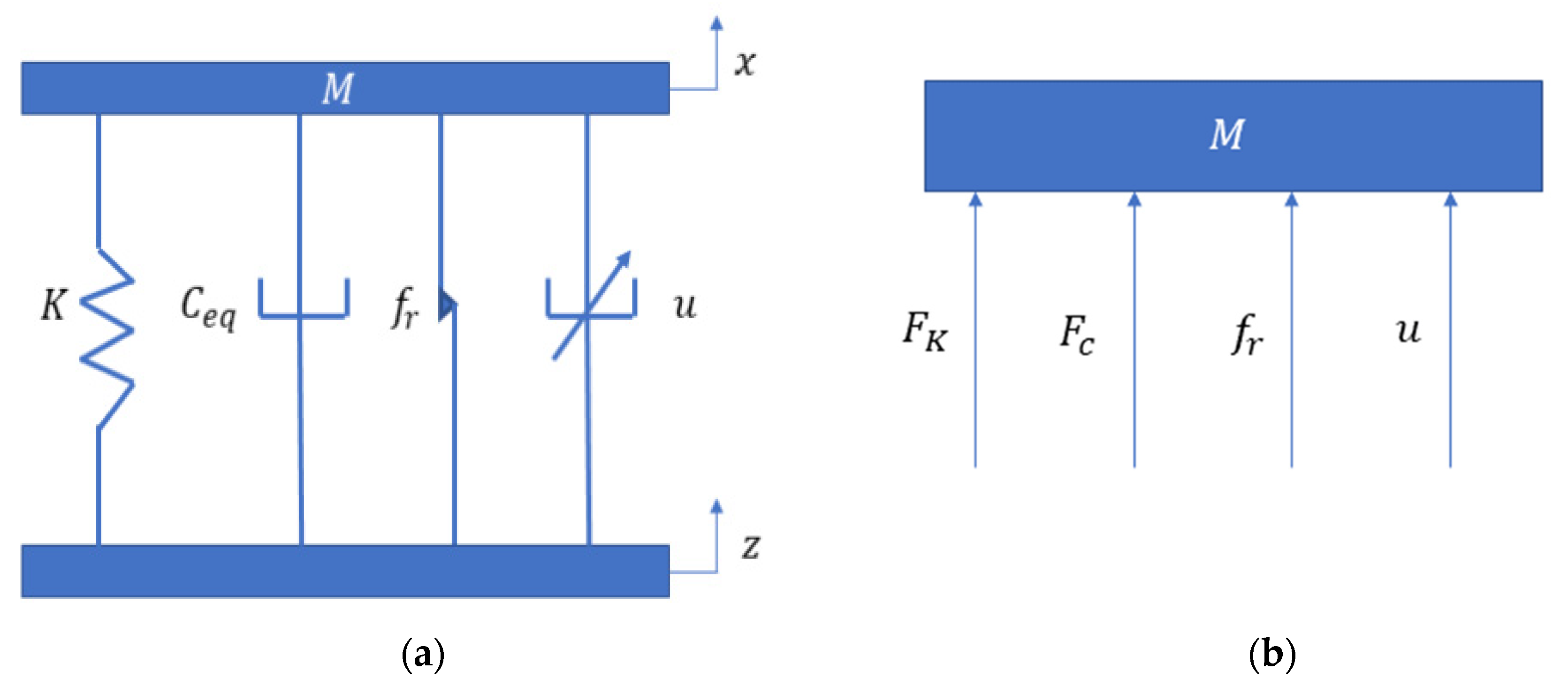
2.1. The Variable Damping Seat Suspension

The model and prototype of the variable damping seat suspension are shown in Figure 1; they consist of a passive spring and a controllable EMD, which are in parallel. The three-phase permanent magnet synchronous motor (PMSM) is connected to the ball screw through a coupling. The ball screw, whose lead is 0.016   m , can transform the torque of the EMD to a vertical force, and the rotary rate of the EMD, ω , is transformed as a vertical velocity, v . In addition, an encoder is applied to record the rotation angle of the motor. In this way, the relative displacement of the seat suspension can be obtained. It is easy to see that this variable damping seat suspension where only the controller and the sensor consume low electric energy without other energy input is a semi-active vibration absorber.

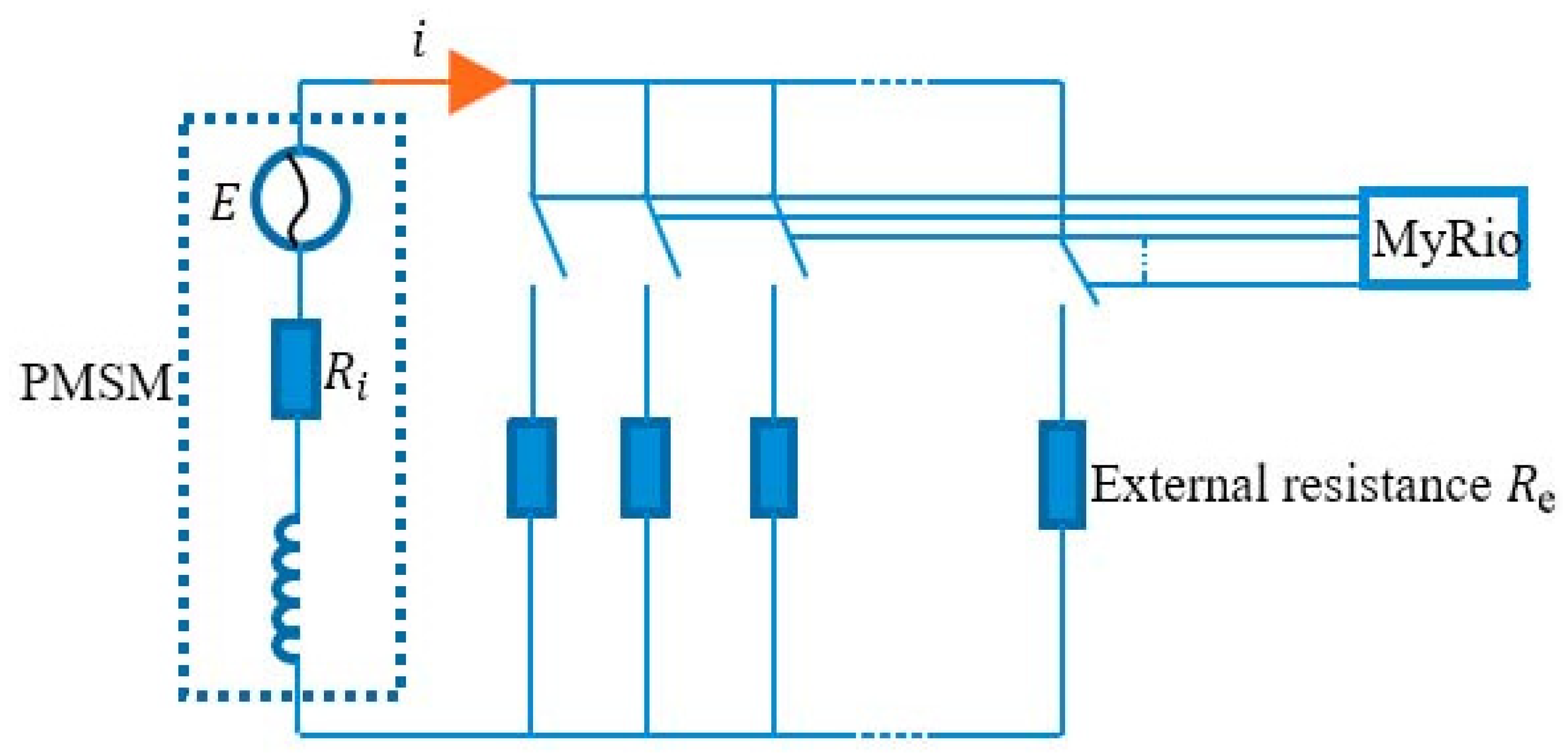
2.2. The Damping Controllable System

The EMD consists of a three-phase servo motor PMSM, a rectifier, and an external resistance unit that can control the device damping [30,31,32]. The PMSM (Panasonic motor, MSMD022G1S) can be modelled as a voltage source, an internal resistor and an internal inductor. The internal inductance can be ignored to simplify the model because the seat vibration is at low frequencies, generally. In addition, a rectifier is applied to convert the alternating current generated by the PMSM to direct current [38].
From [30], the damping of an EMD increases with the decrease of the external loads. In other words, the system has the biggest damping when its external resistance is 0   Ω , and the system has the smallest damping when its external resistance is the biggest. In this article, a 500   Ω resistor is chosen to determine the smallest damping of the system.
The torque of the motor in the EMD is controllable, and the ball screw can transform the torque into a force output. Figure 2 shows the simplified model of the EMD circuit. Multiple resistors are in parallel, and a myRIO can control their connections in the circuit. By adjusting the resistors’ switches, the circuit’s equivalent external resistance will change accordingly.
The equivalent damping force F C and the torque T E M D of the EMD have a relationship as follows:
F C = r b a l l s c r e w · T E M D
where r b a l l s c r e w = 2 π l e a d is the ball screw transmission ratio.
In the circuit of the EMD, there are connections between its torque and the current i :
T E M D = k i · i
where k i is the torque constant of the motor.
According to the Ohm’s law,
i = E R e + R i
where E is the generated voltage, and R i and R e are the internal and external resistance, respectively.
The rotor coil in the EMD cuts the magnetic inductance line to generate electromotive force, and all the circuit elements are connected as a loop. Therefore,
E = k e · ω
where k e is the voltage constant and ω is the rotary rate of the motor.
Ignoring the efficiency loss of the coupling during transmission, the relationship between the relative speed of the two ends of the electromagnetic shock absorber, v , and motor rotor speed ω can be obtained:
ω = r b a l l s c r e w · v
Additionally, in this motor, k i = k e . Thus, the damping C is:
C = r b a l l s c r e w 2 · k i 2 R e + R i
The damping of the seat suspension is related to the ball screw, the torque or voltage constant of the PMSM, and the internal and external resistance. Table 1 shows the parameters of the EMD.
The change in resistance in the circuit can cause a change in device damping. Thus, we can obtain semi-active control of the seat suspension by changing the resistance of the electric circuit.

3. Semi-Active Controller with Prescribed Performance Control

In this section, a semi-active controller with PPC is proposed for the variable damping system. The prescribed performance control method can not only ensure the steady performance of the system, but also meet the requirements of the dynamic performance design by limiting the tracking error of the system to the region constrained by the selected boundary function so that a reasonable performance constraint function boundary can be designed to limit the overshoot, adjustment time and steady-state error of the dynamic response of the tracking error. In this way, the desired control force requirements can be achieved. This seat suspension system also designs a force-tracking strategy in control, as shown in Figure 3. The EMD in seat suspension is used to provide controllable damping force according to the desired control force. The system states change when the vibration or excitation is transmitted to the seat through the suspension. Then, the controller will calculate an ideal force. According to Section 2, a change in the resistance results in a change in damping. In this way, this system can isolate the vibration.

3.1. Problem Description

The whole seat suspension model is shown in Figure 4: Figure 4a is the simplified model of the seat suspension; Figure 4b is the free body diagram, where M is the mass; K is the spring stiffness; C e q is the inherent damping, and it is mainly from friction; and u is the force generated from the semi-active damper. In addition, x is the seat response and z is the excitation. Thus, the dynamic model is:
M x ¨ = F c + F K + f r + u
F K = K · ( x z )
F c = C e q · ( x ˙ z ˙ )
u = C · ( x ˙ z ˙ )
f r = f · s a t ( x ˙ z ˙ )
s a t ( x ˙ z ˙ ) = { 1                                                                   ( x ˙ z ˙ ) > α 1 α ( x ˙ z ˙ )                           α   ( x ˙ z ˙ ) α 1                                                                   ( x ˙ z ˙ ) < α
where C is the controllable damping of the EMD, F c is the damping force, F K is the stiffness force and f r represents the system friction, f is the friction coefficient, and α is the saturation boundary.
The objective of control can be summarized as follows:
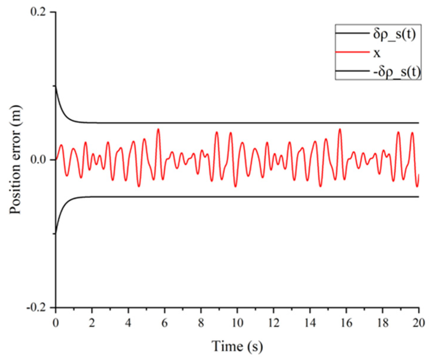
  • The output of the system can track the desired trajectory while maintaining the boundedness of all signals in the closed loop.
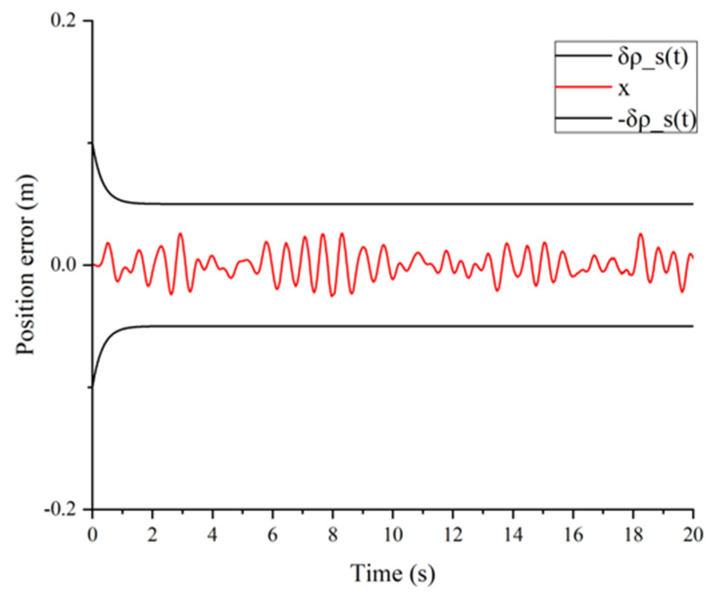
  • The tracking error meets the specified transient and steady-state performance limits.

3.2. The Design of the PPC

In vibration control, the controlled seat suspension is required to meet the ideal position trajectory. Thus, we set the position tracking error e ( t ) as
e ( t ) = x z d
where z d represents the desired displacement, which is set as zero in this paper.
The desired control force will be calculated by using the PPC. The preset performance control in this paper is derived from the reference [33]. By setting a boundary on the position tracking error the preset steady-state and transient performance requirements are achieved, so e ( t ) should be satisfied:
δ ρ s ( t ) < e ( t ) < δ ρ s ( t )
ρ s ( t ) = ( ρ s ( 0 ) ρ s ( ) ) e α t + ρ s ( )
where ρ s ( t )   is performance function, which is strictly monotone and always greater than 0, and δ is the design constant where 0 δ 1 . The constant ρ s ( ) represents the maximum allowable size of the tracking error in the steady state. At the same time, the preset decline rate of the performance function represents the minimum speed of convergence of the allowed tracking error. The choice of an appropriate performance function imposes boundaries on the system output.
Next, we use the error transformation function to transform the constrained tracking error into an equivalent unconstrained behavior:
ζ ( t ) = e ( t ) ρ s ( t )
where ζ ( t ) represents the normalized position error.
Based on [39], the first transformed error is designed as:
z = 1 2 ln ( δ + ζ ( t ) δ ζ ( t ) )
Thus, the intermediate controller u 1 is designed as:
u 1 = k 1 z
where k 1 is a positive constant. It is assumed that the velocity error is e v ( t ) , likewise:
e v ( t ) = x ˙ u 1
The performance function corresponding to the velocity error is ρ v ( t ) :
ρ v ( t ) = ( ρ v ( 0 ) ρ v ( ) ) e β t + ρ v ( )
where ρ v ( ) and β are normal numbers and, as above, the transient and steady-state responses of the velocity need to satisfy. Additionally, similarly:
ξ ( t ) = e v ( t ) ρ v ( t )
τ = 1 2 ln ( δ + ξ ( t ) δ ξ ( t ) )
where τ is second transformed error. Then, we can obtain the desired PPC force:
u = k 2 τ
where k 2 is a positive constant and u is F d e s i r e d .
There is a conclusion that the proposed control strategy can realize the transient- and steady-state. The proof of this has been developed in [33,36,40].

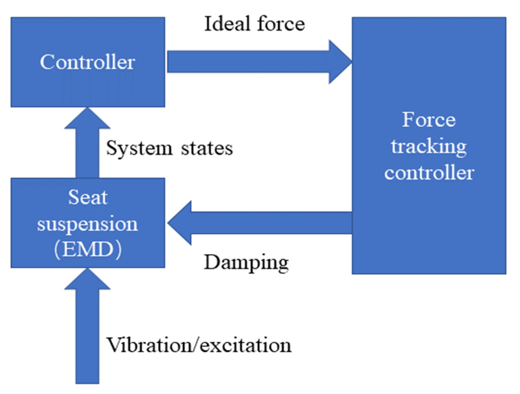
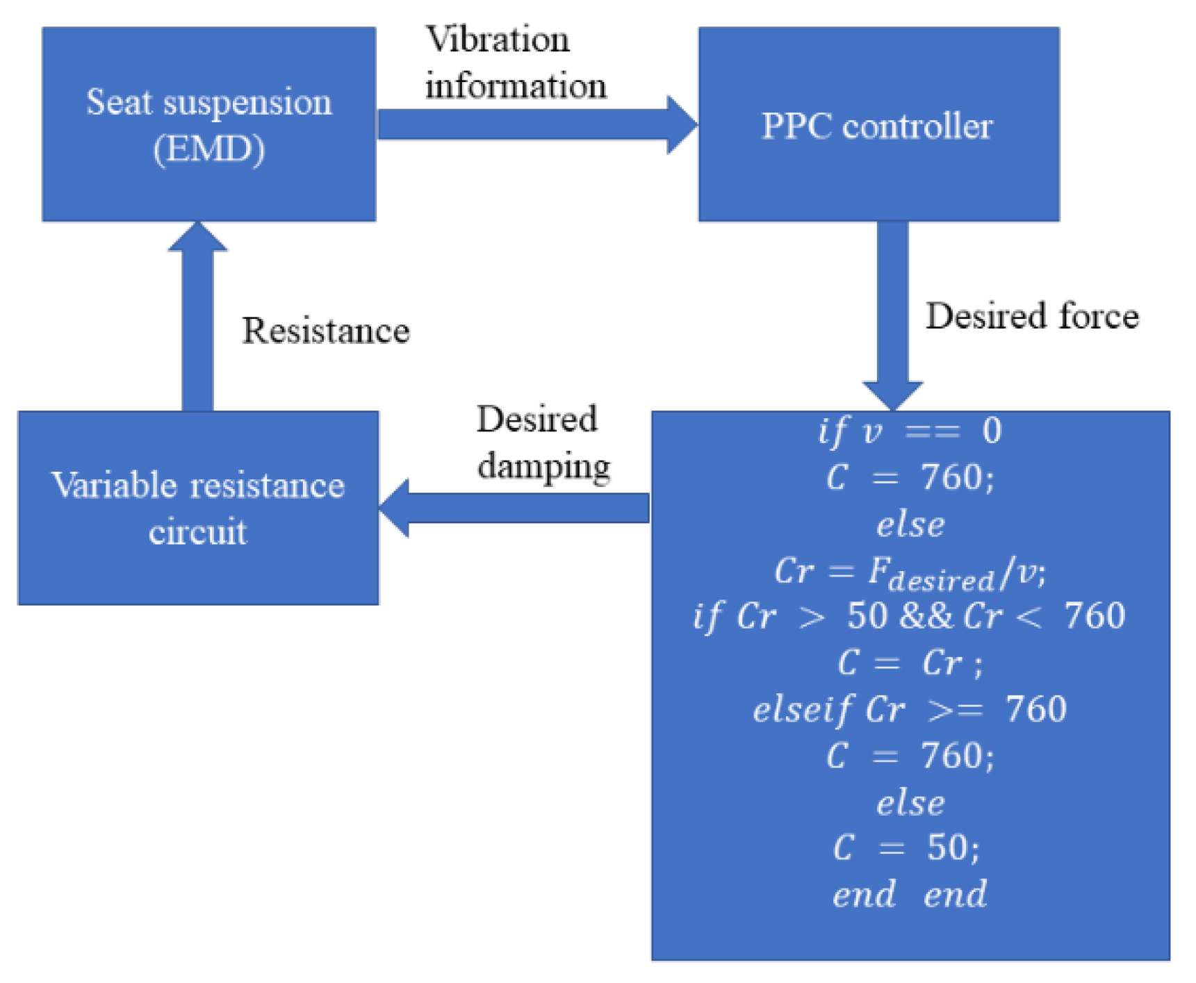
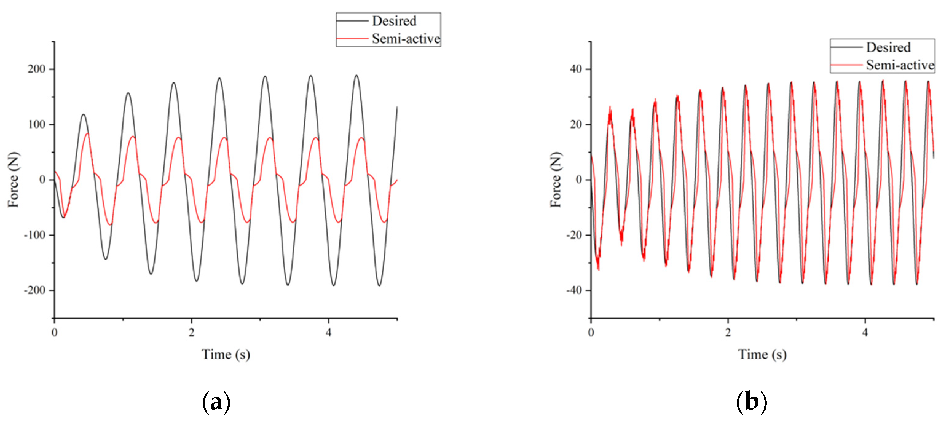
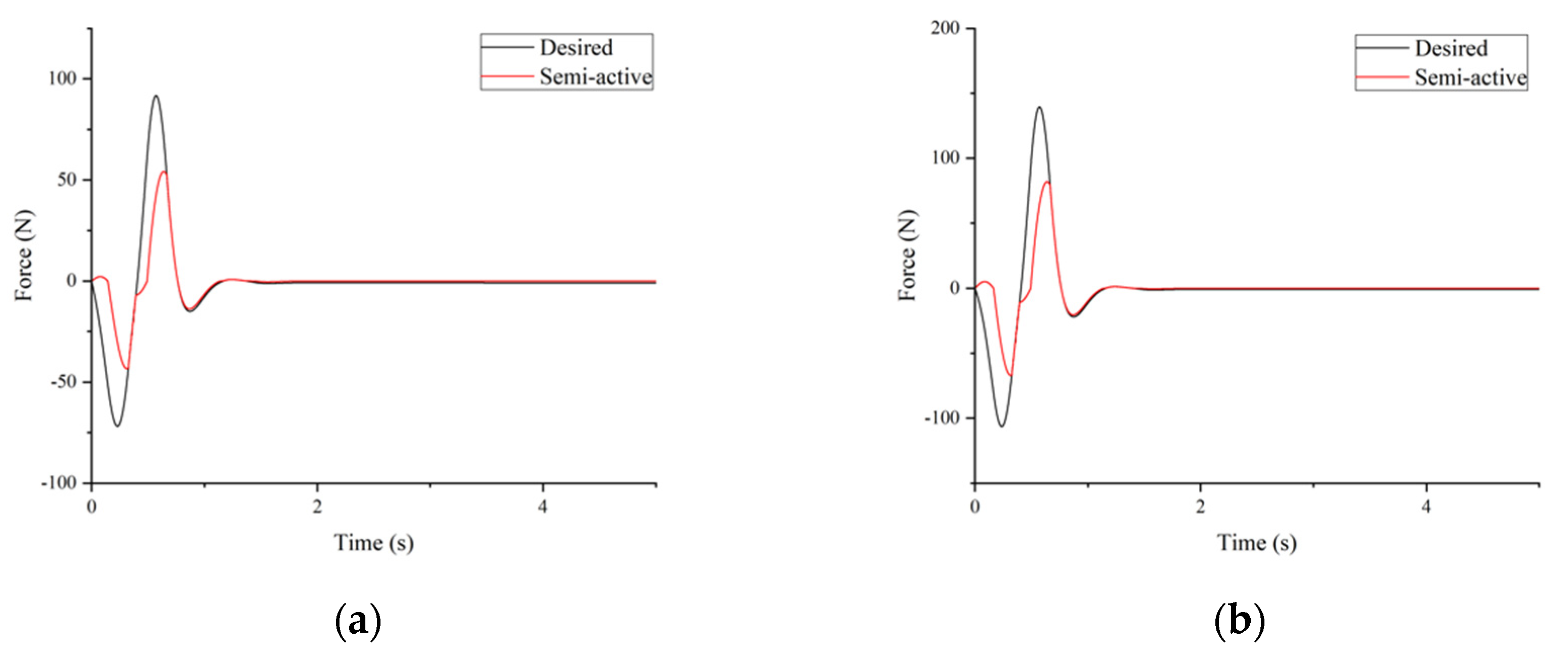
3.3. Force Tracking Strategy

A desired control force can be calculated in the last section. Then, a force tracking strategy is required to control the EMD. This process can be divided into two steps. In the first step, according to the ideal or desired force and the system’s conditions, the desired damping can be calculated based on Figure 5. According to Equation (5) and Figure 5, the damping C is varied with the external resistance R e . The control of R e has been proposed in [38]. In this paper, the parallel resistors are selected as 0.1   Ohm , 50   Ohm , 100   Ohm , 150   Ohm , 200   Ohm , 300   Ohm , and 500   Ohm , respectively. Different resistor combinations can generate different external resistance. Hence, the largest damping of the EMD is 760   N · s / m , when the resistance is lowest. When the resistance is the largest, the value of damping is 50   N · s / m . When the controller calculates the desired damping C and the corresponding resistance, a controller will control the electric circuit to generate the resistance that is closest to the target resistance, by controlling the circuit of the EMD.

4. Performance Evaluation

This section provides simulations and experiments to validate the seat suspension’s performance. The seat suspension was tested by simulation at first. Then, a designed platform was utilized to test the semi-active seat suspension prototype. These two methods were used to evaluate the performance of the seat suspension. The parameters of the system are shown in Table 2.

4.1. Numerical Analysis

This section will use different excitations to evaluate the controller performance with numerical simulation. A traditional passive suspension is used to compare, in which constant damping is applied to replace the EMD. The controller’s performance functions are set as ρ s ( t ) = ( 0.1 0.05 ) e 3 t + 0.05 and ρ v ( t ) = ( 1 0.5 ) e 1.5 t + 0.5 . The other preset parameters are k 1 = 0.01 ,   k 2 = 500   and   δ = 1 .

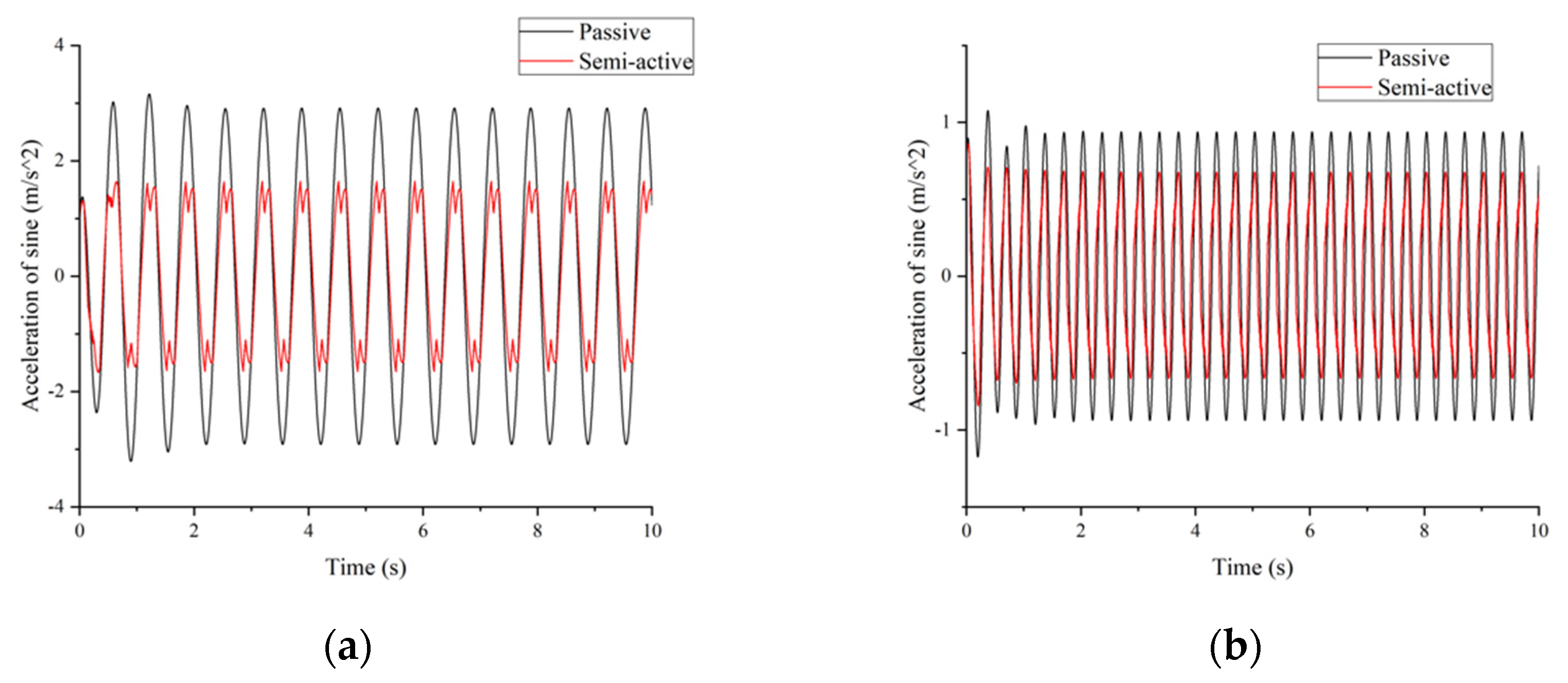
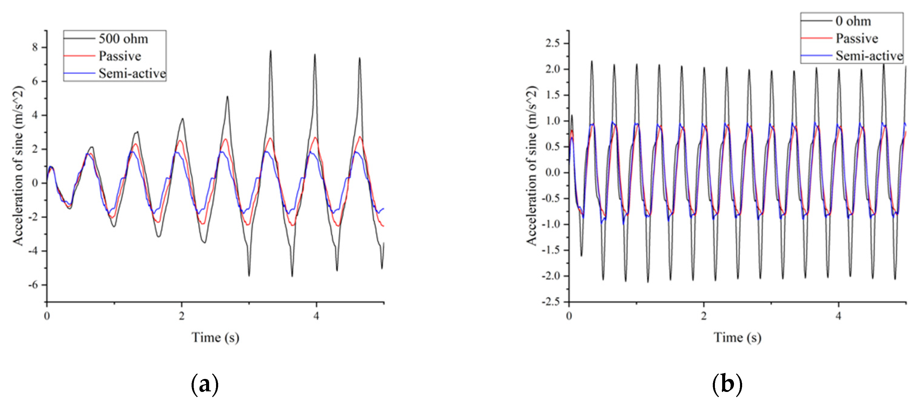
4.1.1. Sine Vibration Simulation

Figure 6 shows the comparison of acceleration response to the sine wave excitation in the time domain. The systems are traditional passive seats with a spring and a damper and the semi-active EMD system. These sine wave amplitudes are 14   mm and 4   mm , and the frequencies are 1.5   Hz and 3   Hz , respectively. The semi-active system has a smaller acceleration, and the root mean square (RMS) was reduced by 42.8 % and 27.9 % compared to the passive system. Figure 7 shows the tracking force performance of the controller. From the figures, the semi-system can successfully follow the desired force in most regions.

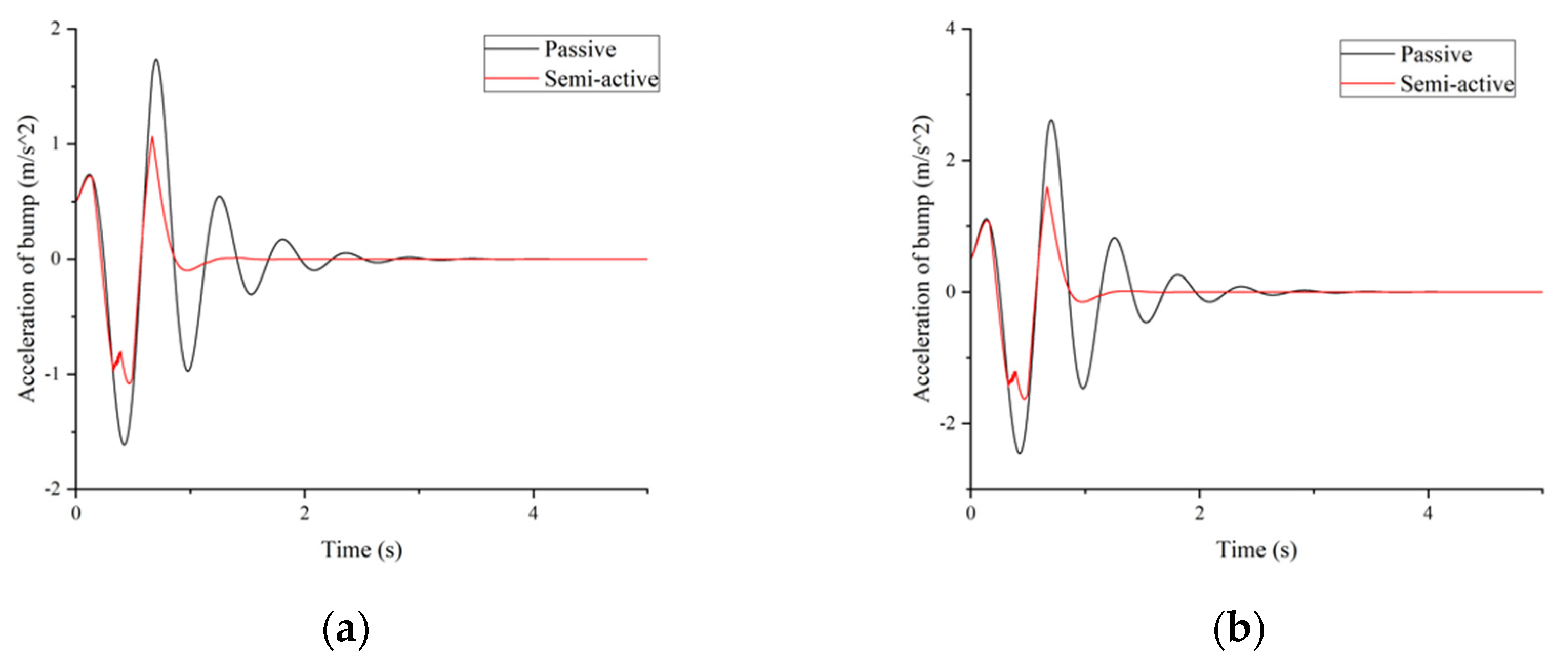
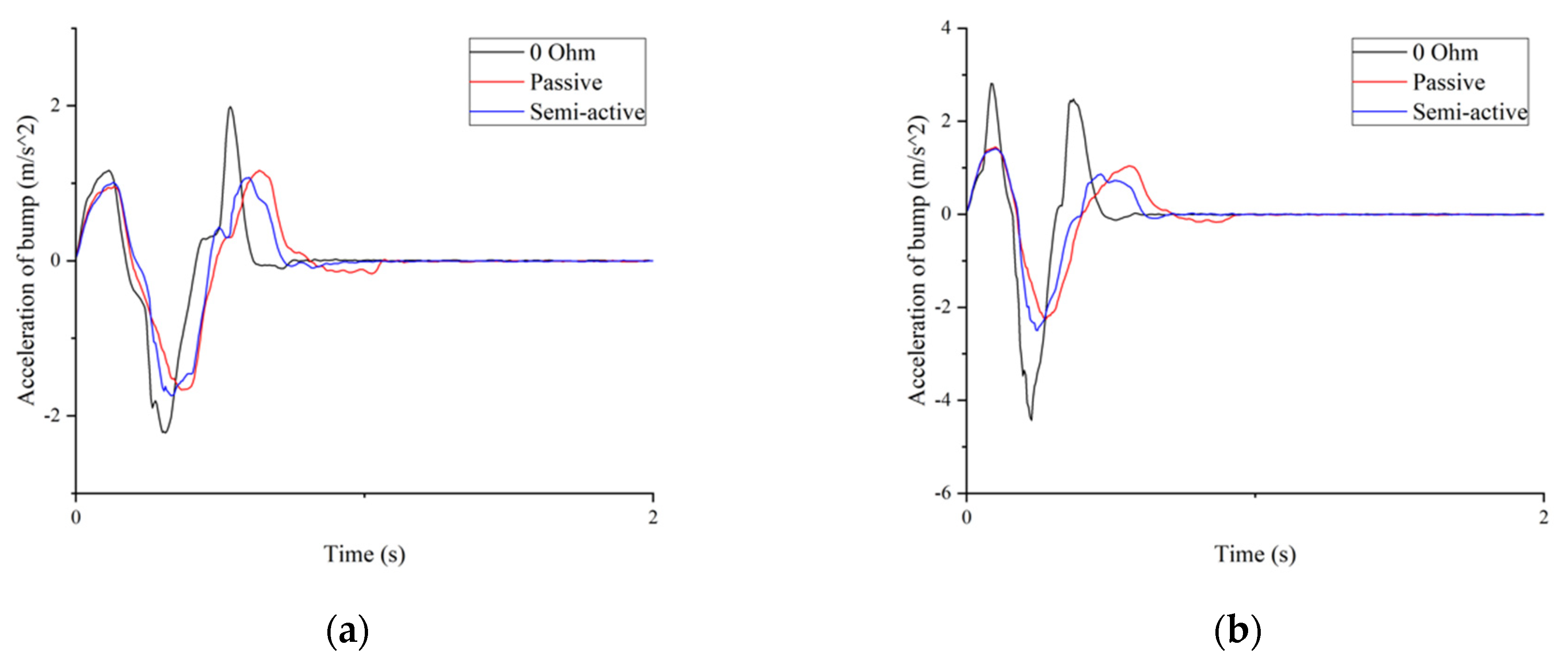
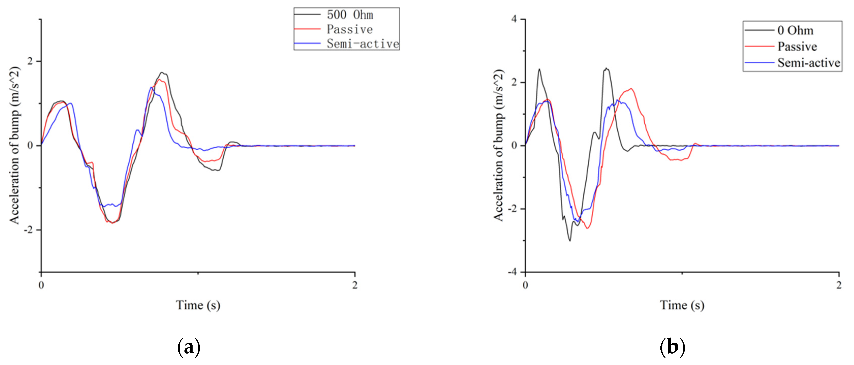
4.1.2. Bump Vibration Simulation

Figure 8 shows the response to bump excitation in the simulation. The peak-to-peak value in Figure 8 is 3.35   m / s 2 for the passive system, and 2.14   m / s 2 for the semi-active system in Figure 8a. Additionally, 5.07   m / s 2   for the passive system and 3.23   m / s 2 for the semi-active system are shown in Figure 8b. The reductions are 36.1 % and 36.3 % , respectively. Figure 9 shows the force tracking performance. The figures show that the semi-active system can follow the desired force for most situations.

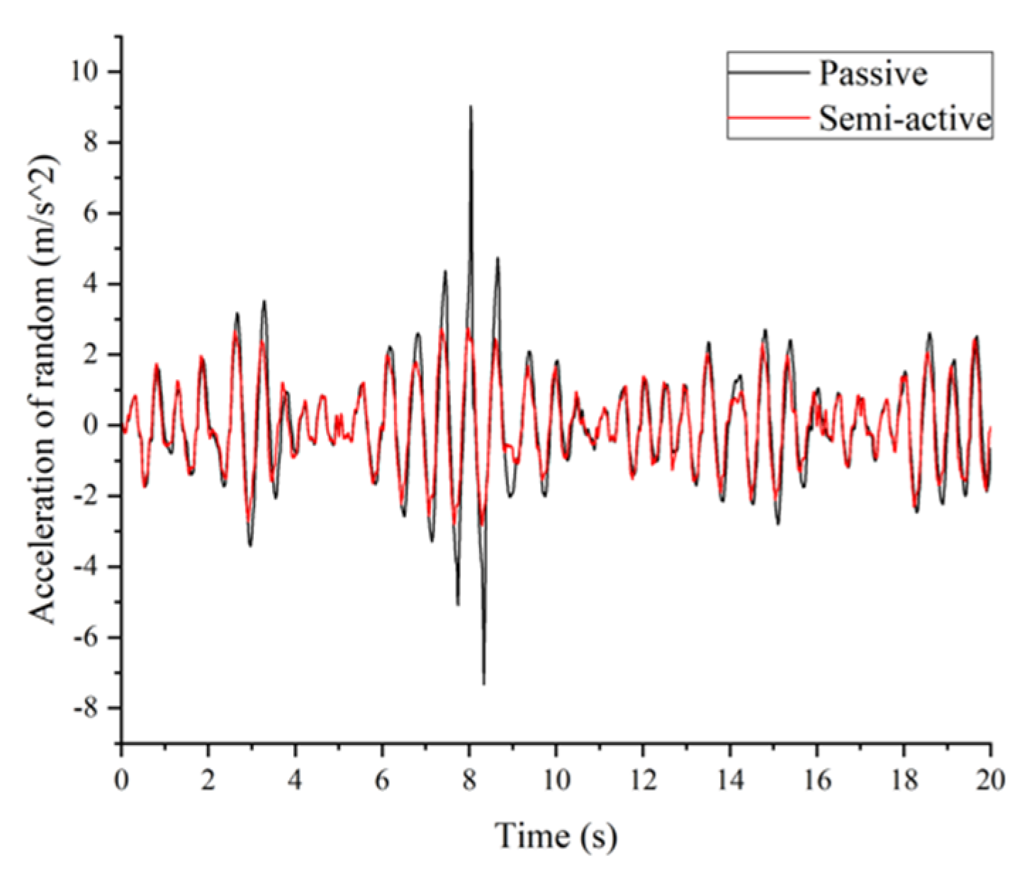
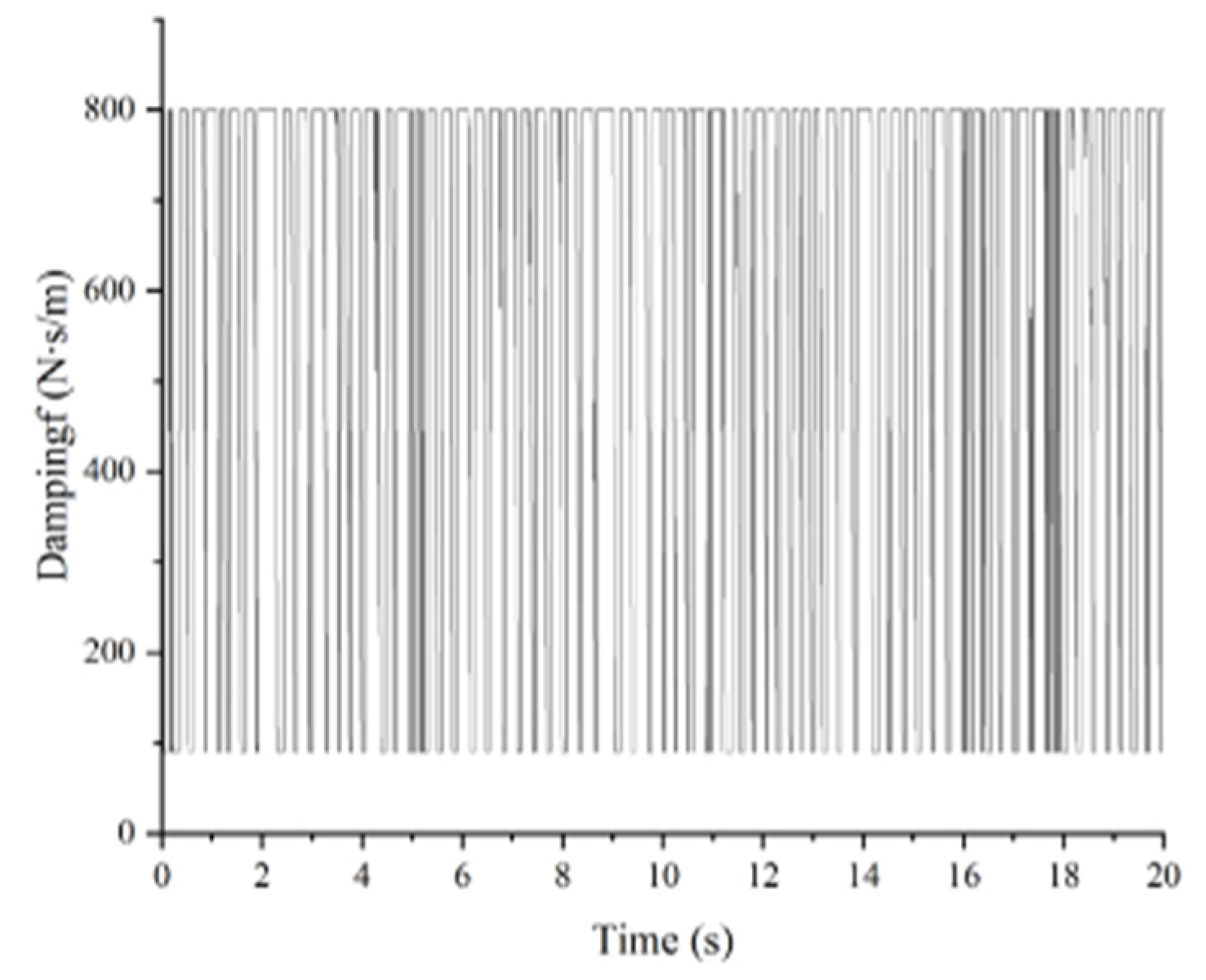
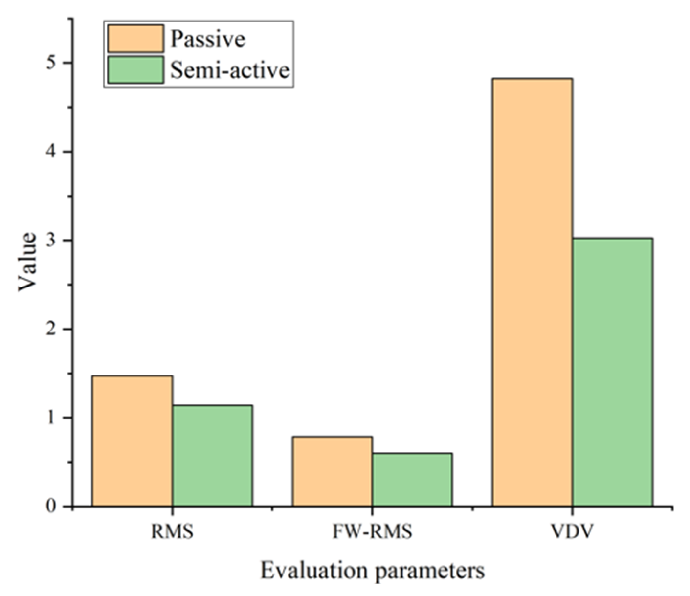
4.1.3. Random Vibration Simulation
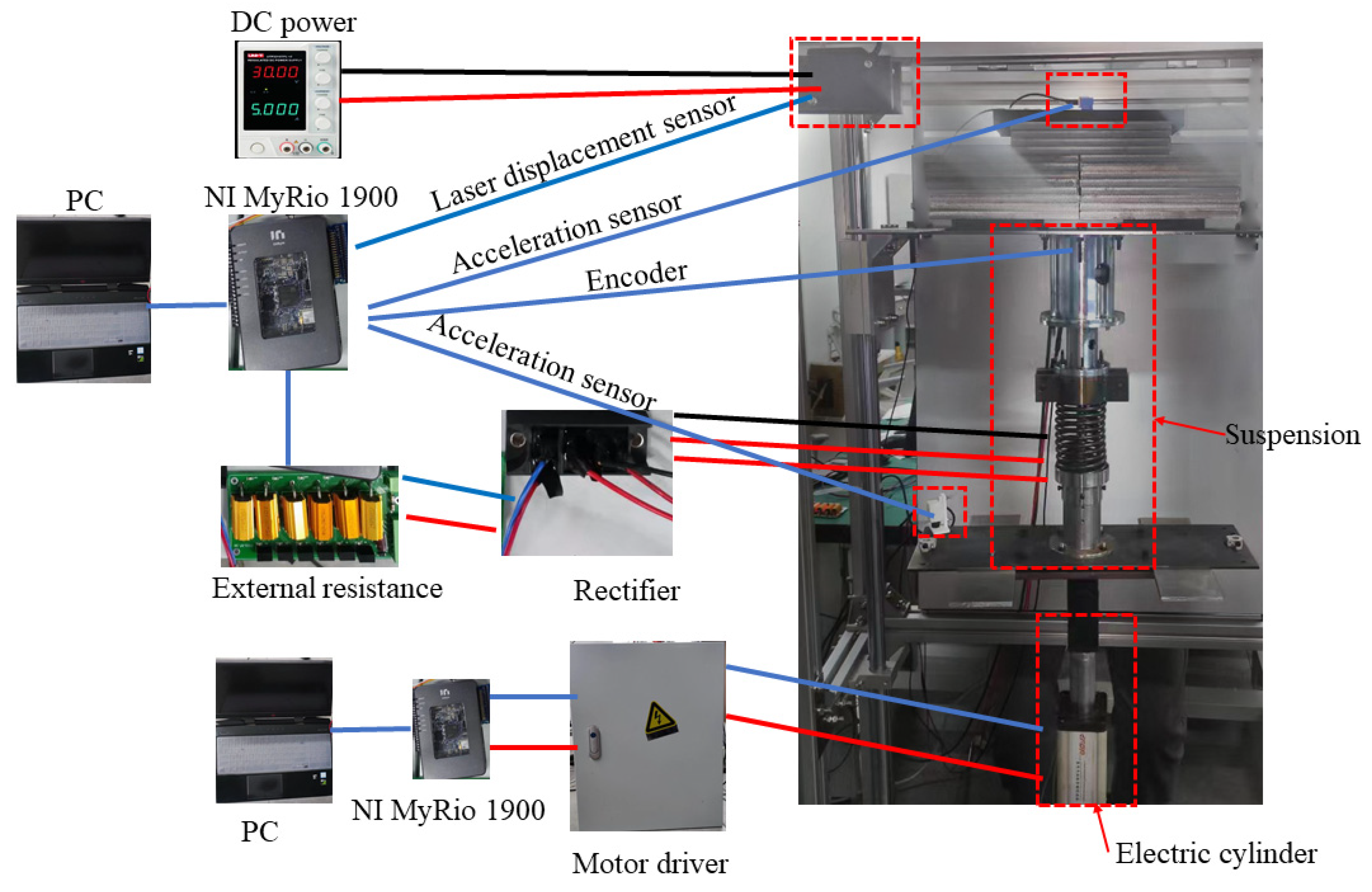
The random signal is also taken into consideration compared to the traditional system. The results of the simulation are shown in Figure 10. The RMS accelerations are 3.52   m / s 2 for the passive system and 2.17   m / s 2 for the semi-active system. The semi-active system has a 38.4 % improvement compared to the passive one. Finally, Figure 11 shows the position error, which is always within the predefined boundaries.

4.2. Experiment

4.2.1. Experimental Setup

The test system consists of a frame made of aluminum alloy bars and an electric cylinder controlled by NI MyRIO, as shown in Figure 12. Two accelerometers, 1C101 of DONGHUA and ADXL 103, are used to measure the acceleration of the seat suspension. The rotary encoder, ORMOU E6H-CWZ, is used to test the rotary of the EMD for calculating the suspension relative displacement. Additionally, the seat suspension displacement is measured by a KathMatic laser displacement sensor whose measuring range is from   90   mm to 190   mm . The experimental system can be divided into three parts: vibration platform, test system and seat suspension. The single-freedom vibration platform, which is under the control of an NI myRIO, consists of a PC, a motor driver and an electric cylinder. Based on the PC’s command, the platform can generate different excitations. The test system consists of an acceleration sensor, a displacement sensor, an NI myrio and a DC power, which supplied power for the sensor.
Sine wave, bump, and random excitations are used to evaluate the proposed seat suspension performance. A typical road condition through a quarter-car model generates a random vibration signal. In these different tests, the seat suspension is set as three different conditions, with an external resistor at 0   Ohm , 500   Ohm and 88   Ohm . The value of 0   Ohm represents the maximum damping, 500   Ohm   represents minimum damping, and 88   Ohm is applied to simulate a passive suspension. The international standard ISO 2631-1 [41] is applied to evaluate the seat suspension vibration isolation performance. Therefore, there are three parameters used to evaluate the performance, including the root mean square (RMS), the frequency-weighted RMS (FW-RMS) acceleration and the fourth power vibration dose value (VDV). According to the international standard, the FW-RMS and the VDV can be calculated as:
a F W R M S = [ 1 T 0 T { a F W R M S ( t ) 2 d t } ] 1 2
VDV = [ 1 T 0 T { a W ( t ) 4 d t } ] 1 4

4.2.2. Sine Vibration Test

Figure 13 shows the seat acceleration comparison with different external resistors of the sine wave. In Figure 13a, the excitation amplitude is 14   mm and the frequency is 1.5   Hz , which is the resonance frequency; the seat suspension shows resonance when the damping is small. The RMS value in Figure 13a is 1.58   m / s 2 for the passive system and 1.20   m / s 2 for the semi-active system, where there is a 24.1 % reduction. This illustrates that the semi-active system generates large damping to suppress the resonance vibration. For Figure 13b, the semi-active system has a performance close to the passive because the equivalent damping of the EMD seat caused by the friction in 3 Hz is close to the damping of the passive seat. In addition, the semi-active and passive suspensions perform better than the EMD suspension with 0 Ohm external resistance.

4.2.3. Bump Vibration Test

The acceleration comparison of bump signals of different frequencies is shown in Figure 14. The amplitude of the bump is 20   mm , while the frequency is 2   Hz and   3   Hz , respectively. Figure 15 shows the acceleration comparison where the amplitude is 30   mm and the frequency is 1.5   Hz and 2   Hz , as well. In these chats, the semi-active system has a lower peak value. The results demonstrate that the proposed seat suspension has better performance at the high frequency where the EMD has low damping.

4.2.4. Random Vibration Test

Finally, the random excitation is transmitted to the seat suspension in Figure 16. The passive seat has a high peak acceleration, and the semi-active seat suspension can effectively suppress the resonance vibration. The change of damping under control is shown in Figure 17. Figure 18 shows that position errors with prescribed performance are bounded for all times. Then, Figure 19 shows the evaluation parameters of acceleration according to ISO 2631-1. Compared to the passive system, the semi-active is improved by 17.5 % for RMS,   39.9 % for FW-RMS and 25.4 % for VDV.

5. Conclusions

In this paper, an EMD seat suspension with a PPC-based semi-active controller was developed and tested. First, an EMD prototype was built with a PMSM, a ball screw, a three-phase rectifier, and a controllable external resistor. By changing the resistance of the external resistor in real-time, the damping of the EMD can vary from 90 to 800 N · s / m . Hence, it can generate large damping when it needs to suppress the high-magnitude resonance vibration and provide small damping to guarantee ride comfort. Then, a PPC-based semi-active controller was designed to control the EMD for vibration control, where the PPC can guarantee the desired prescribed performance bound. Furthermore, a semi-active strategy has been proposed to control the external resistor of the EMD for generating a semi-active control force. Finally, a test platform has been designed and manufactured to validate the performance of the semi-active seat suspension and the proposed controller. When the seat suspension is in control, the RMS, FW-RMS and VDV of the seat acceleration are reduced by 17.5%, 39.9% and 25.4%, respectively, compared with a passive suspension. The simulation and the experiment prove that this approach is useful and promising. In the future, we will further explore the characteristics of the EMD system and develop controllers for high-performance vibration control.

Author Contributions

Conceptualization, J.Z., D.N. and J.Y.; methodology, D.N. and D.L.; validation, J.Z. and P.L.; writing—original draft preparation, J.Z.; writing—review and editing, D.N.; supervision, D.N.; experiment, J.Z., H.Z. and G.L. All authors have read and agreed to the published version of the manuscript.

Funding

This research was funded by the National Natural Science Foundation of China (Grant No. 52088102) and Nature Science Foundation of Shandong Project (Grant No. 2022HWYQ-067).

Data Availability Statement

Not applicable.

Conflicts of Interest

The authors declare no conflict of interest.

References

  1. Dennerlein, J.T.; Cavallari, J.M.; Kim, J.H.J.; Green, N.H. The effects of a new seat suspension system on whole body vibration exposure and driver low back pain and disability: Results from a randomized controlled trial in truck drivers. Appl. Ergon. 2022, 98, 103588. [Google Scholar] [CrossRef] [PubMed]
  2. Virtanen, I.M.; Karppinen, J.; Taimela, S.; Ott, J.; Barral, S.; Kaikkonen, K.; Heikkilä, O.; Mutanen, P.; Noponen, N.; Männikkö, M.; et al. Occupational and Genetic Risk Factors Associated with Intervertebral Disc Disease. Spine 2007, 32, 1129–1134. [Google Scholar] [CrossRef]
  3. Paddan, G.S.; Griffin, M.J. Evaluation of Whole-Body Vibration in Vehicles. J. Sound Vib. 2002, 253, 195–213. [Google Scholar] [CrossRef]
  4. Pazooki, A.; Rakheja, S.; Cao, D. Modeling and validation of off-road vehicle ride dynamics. Mech. Syst. Signal Process. 2012, 28, 679–695. [Google Scholar] [CrossRef] [Green Version]
  5. Stein, G.J.; Múčka, P. Study of simultaneous shock and vibration control by a fore-and-aft suspension system of a driver’s seat. Int. J. Ind. Ergon. 2011, 41, 520–529. [Google Scholar] [CrossRef]
  6. Pazooki, A.; Cao, D.; Rakheja, S.; Boileau, P.-É. Ride dynamic evaluations and design optimisation of a torsio-elastic off-road vehicle suspension. Veh. Syst. Dyn. 2011, 49, 1455–1476. [Google Scholar] [CrossRef] [Green Version]
  7. Velmurugan, P.; Kumaraswamidhas, L.A.; Sankaranarayanasamy, K. Whole Body Vibration Analysis for Drivers of Suspended Cabin Tractor Semitrailer. Exp. Tech. 2014, 38, 47–53. [Google Scholar] [CrossRef]
  8. Zhao, X.; Kremb, M.; Schindler, C. Assessment of wheel loader vibration on the riding comfort according to ISO standards. Veh. Syst. Dyn. 2013, 51, 1548–1567. [Google Scholar] [CrossRef]
  9. Carrella, A. Passive Vibration Isolators with High-Static-Low-Dynamic-Stiffness; University of Southampton: Southampton, UK, 2008. [Google Scholar]
  10. Carrella, A.; Brennan, M.J.; Waters, T.P.; Lopes, V. Force and displacement transmissibility of a nonlinear isolator with high-static-low-dynamic-stiffness. Int. J. Mech. Sci. 2012, 55, 22–29. [Google Scholar] [CrossRef]
  11. Carrella, A.; Brennan, M.J.; Waters, T.P.; Shin, K. On the design of a high-static–low-dynamic stiffness isolator using linear mechanical springs and magnets. J. Sound Vib. 2008, 315, 712–720. [Google Scholar] [CrossRef]
  12. Carrella, A.; Brennan, M.J.; Waters, T.P. Static analysis of a passive vibration isolator with quasi-zero-stiffness characteristic. J. Sound Vib. 2007, 301, 678–689. [Google Scholar] [CrossRef]
  13. Le, T.D.; Ahn, K.K. A vibration isolation system in low frequency excitation region using negative stiffness structure for vehicle seat. J. Sound Vib. 2011, 330, 6311–6335. [Google Scholar] [CrossRef]
  14. Le, T.D.; Ahn, K.K. Experimental investigation of a vibration isolation system using negative stiffness structure. Int. J. Mech. Sci. 2013, 70, 99–112. [Google Scholar] [CrossRef]
  15. Yan, Z.; Zhu, B.; Li, X.; Wang, G. Modeling and Analysis of Static and Dynamic Characteristics of Nonlinear Seat Suspension for Off-Road Vehicles. Shock. Vib. 2015, 2015, 1–13. [Google Scholar] [CrossRef] [Green Version]
  16. Zheng, Y.; Zhang, X.; Luo, Y.; Yan, B.; Ma, C. Design and experiment of a high-static–low-dynamic stiffness isolator using a negative stiffness magnetic spring. J. Sound Vib. 2016, 360, 31–52. [Google Scholar] [CrossRef]
  17. Han, Y.; Cao, Q.; Ji, J. Nonlinear Dynamics of a Smooth and Discontinuous Oscillator with Multiple Stability. Int. J. Bifurc. Chaos 2016, 25, 1530038. [Google Scholar] [CrossRef]
  18. Gan, Z.; Hillis, A.J.; Darling, J. Adaptive control of an active seat for occupant vibration reduction. J. Sound Vib. 2015, 349, 39–55. [Google Scholar] [CrossRef] [Green Version]
  19. Ning, D.; Sun, S.; Li, H.; Du, H.; Li, W. Active control of an innovative seat suspension system with acceleration measurement based friction estimation. J. Sound Vib. 2016, 384, 28–44. [Google Scholar] [CrossRef]
  20. Ning, D.; Sun, S.; Zhang, F.; Du, H.; Li, W.; Zhang, B. Disturbance observer based Takagi-Sugeno fuzzy control for an active seat suspension. Mech. Syst. Signal Process. 2017, 93, 515–530. [Google Scholar] [CrossRef] [Green Version]
  21. Choi, S.-B.; Han, Y.-M. Vibration control of electrorheological seat suspension with human-body model using sliding mode control. J. Sound Vib. 2007, 303, 391–404. [Google Scholar] [CrossRef]
  22. Choi, S.-B.; Nam, M.-H.; Lee, B.-K. Vibration control of a MR seat damper for commercial vehicles. J. Intell. Mater. Syst. Struct. 2000, 11, 936–944. [Google Scholar] [CrossRef]
  23. Sun, S.S.; Ning, D.H.; Yang, J.; Du, H.; Zhang, S.W.; Li, W.H. A seat suspension with a rotary magnetorheological damper for heavy duty vehicles. Smart Mater. Struct. 2016, 25, 105032. [Google Scholar] [CrossRef] [Green Version]
  24. Zhu, T.; Wan, H.; Wang, Z.; Wei, M.; Xu, X.; Zou, Z.; Du, S. Model Reference Adaptive Control of Semi-active Suspension Model Based on AdaBoost Algorithm for Rollover Prediction. SAE Int. J. Veh. Dyn. Stab. NVH 2022, 6, 71–86. [Google Scholar]
  25. Pires, L.; Smith, M.C.; Houghton, N.E.; McMahon, R.A. Design trade-offs for energy regeneration and control in vehicle suspensions. Int. J. Control. 2013, 86, 2022–2034. [Google Scholar] [CrossRef]
  26. Wang, R.; Ding, R.; Chen, L. Application of hybrid electromagnetic suspension in vibration energy regeneration and active control. J. Vib. Control. 2018, 24, 223–233. [Google Scholar] [CrossRef]
  27. Khoshnoud, F.; Sundar, D.B.; Badi, M.N.M.; Chen, Y.K.; Calay, R.K.; Silva, C.W.D. Energy harvesting from suspension systems using regenerative force actuators. Int. J. Veh. Noise Vib. 2013, 9, 294. [Google Scholar] [CrossRef] [Green Version]
  28. Gupta, A.; Jendrzejczyk, J.A.; Mulcahy, T.M.; Hull, J.R. Design of electromagnetic shock absorbers. Int. J. Mech. Mater. Des. 2006, 3, 285–291. [Google Scholar] [CrossRef]
  29. Zhang, J.Q.; Peng, Z.Z.; Lei, Z.; Yu, Z. A Review on Energy-Regenerative Suspension Systems for Vehicles. In Proceedings of the World Congress on Engineering, London, UK, 3–5 July 2013; pp. 3–5. [Google Scholar]
  30. Li, Z.; Zuo, L.; Luhrs, G.; Lin, L.; Qin, Y.-X. Electromagnetic Energy-Harvesting Shock Absorbers: Design, Modeling, and Road Tests. IEEE Trans. Veh. Technol. 2013, 62, 1065–1074. [Google Scholar] [CrossRef]
  31. Zhang, Y.; Chen, H.; Guo, K.; Zhang, X.; Eben Li, S. Electro-hydraulic damper for energy harvesting suspension: Modeling, prototyping and experimental validation. Appl. Energy 2017, 199, 1–12. [Google Scholar] [CrossRef]
  32. Ning, D.; Du, H.; Sun, S.; Li, W.; Li, W. An Energy Saving Variable Damping Seat Suspension System with Regeneration Capability. IEEE Trans. Ind. Electron. 2018, 65, 8080–8091. [Google Scholar] [CrossRef] [Green Version]
  33. Bechlioulis, C.P.; Rovithakis, G.A. Adaptive control with guaranteed transient and steady state tracking error bounds for strict feedback systems. Automatica 2009, 45, 532–538. [Google Scholar] [CrossRef]
  34. Bechlioulis, C.P.; Rovithakis, G.A. A low-complexity global approximation-free control scheme with prescribed performance for unknown pure feedback systems. Automatica 2014, 50, 1217–1226. [Google Scholar] [CrossRef]
  35. Gai, W.; Wang, H.; Zhang, J.; Li, Y. Adaptive Neural Network Dynamic Inversion with Prescribed Performance for Aircraft Flight Control. J. Appl. Math. 2013, 2013, 452653. [Google Scholar] [CrossRef] [Green Version]
  36. Bechlioulis, C.P.; Doulgeri, Z.; Rovithakis, G.A. Guaranteeing prescribed performance and contact maintenance via an approximation free robot force/position controller. Automatica 2012, 48, 360–365. [Google Scholar] [CrossRef]
  37. Wang, Z.; Qin, Y.; Hu, C.; Dong, M.; Li, F. Fuzzy Observer-Based Prescribed Performance Control of Vehicle Roll Behavior via Controllable Damper. IEEE Access 2019, 7, 19471–19487. [Google Scholar] [CrossRef]
  38. Liu, P.; Ning, D.; Luo, L.; Zhang, N.; Du, H. An Electromagnetic Variable Inertance and Damping Seat Suspension with Controllable Circuits. IEEE Trans. Ind. Electron. 2022, 69, 2811–2821. [Google Scholar] [CrossRef]
  39. Huang, Y.; Na, J.; Wu, X.; Gao, G. Approximation-Free Control for Vehicle Active Suspensions with Hydraulic Actuator. IEEE Trans. Ind. Electron. 2018, 65, 7258–7267. [Google Scholar] [CrossRef]
  40. Bechlioulis, C.P.; Rovithakis, G.A. Robust Adaptive Control of Feedback Linearizable MIMO Nonlinear Systems with Prescribed Performance. IEEE Trans. Autom. Control 2008, 53, 2090–2099. [Google Scholar] [CrossRef]
  41. ISO 2631-1; Mechanical Vibration and Shock—Evaluation of Human Exposure to Whole-Body Vibration—Part 1: General Requirements. ISO: London, UK, 1997.
Figure 1. The variable damping seat suspension.
Vibration 06 00019 g001
Figure 2. Simplified system model.
Vibration 06 00019 g002
Figure 3. Control system.
Vibration 06 00019 g003
Figure 4. The seat suspension mode: (a) the simplified seat model; (b) the free body diagram.
Vibration 06 00019 g004
Figure 5. Force tracking strategy.
Vibration 06 00019 g005
Figure 6. Simulation comparison of sine wave excitation in the time domain: (a) is 14   mm and 1.5   Hz ; (b) is 4   mm and 3   Hz .
Vibration 06 00019 g006
Figure 7. Force tracking results: (a) is 14   mm and 1.5   Hz ; (b) is 4   mm and 3   Hz .
Vibration 06 00019 g007
Figure 8. Simulation comparison of bump excitation in the time domain: (a) is   20   mm and 1.5   Hz ; (b) is 30   mm   and 1.5   Hz .
Vibration 06 00019 g008
Figure 9. Force tracking results: (a) is   20   mm and 1.5   Hz ; (b) is 30   mm   and 1.5   Hz .
Vibration 06 00019 g009
Figure 10. Simulation comparison of random excitation in the time domain.
Vibration 06 00019 g010
Figure 11. Position error in simulation.
Vibration 06 00019 g011
Figure 12. The test system.
Vibration 06 00019 g012
Figure 13. Acceleration comparison with different external resistors of the sine wave: (a) is 14   mm and 1.5   Hz ; (b) is 4   mm and   3   Hz .
Vibration 06 00019 g013
Figure 14. Acceleration comparison: (a) is 20 mm and 2 Hz; (b) is 20 mm and 3 Hz.
Vibration 06 00019 g014
Figure 15. Acceleration comparison: (a) is 30 mm and 1.5 Hz; (b) is 30 mm and 2 Hz.
Vibration 06 00019 g015
Figure 16. Acceleration comparison with different systems.
Vibration 06 00019 g016
Figure 17. Variable damping.
Vibration 06 00019 g017
Figure 18. Position error in experiments.
Vibration 06 00019 g018
Figure 19. Evaluation parameters.
Vibration 06 00019 g019
Table 1. The parameters of the EMD.
SymbolValue
r b a l l s c r e w 2 π 0.016 rad / m
k i 0.4
k e 0.4
R i 10.5   Ω
Table 2. Parameters.
SymbolValue
M 60   kg
K 7200   N / m
C e q 60   N / m
f 30   N
Disclaimer/Publisher’s Note: The statements, opinions and data contained in all publications are solely those of the individual author(s) and contributor(s) and not of MDPI and/or the editor(s). MDPI and/or the editor(s) disclaim responsibility for any injury to people or property resulting from any ideas, methods, instructions or products referred to in the content.

