
Vibration Characteristics Control of Resonance Point in Vehicle: Fundamental Considerations of Control System without Displacement and Velocity Information
 , and
, and
Abstract
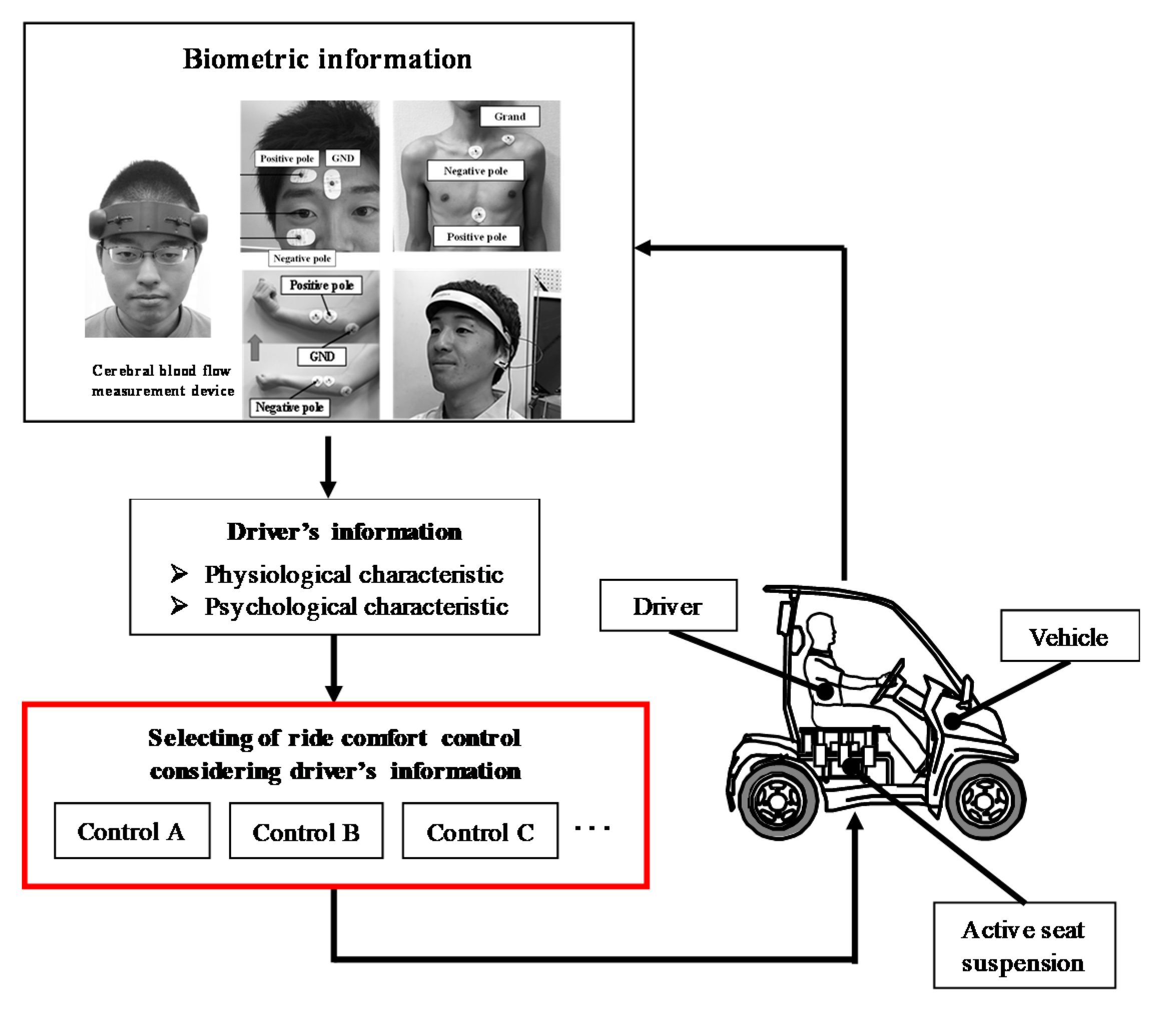
:1. Introduction
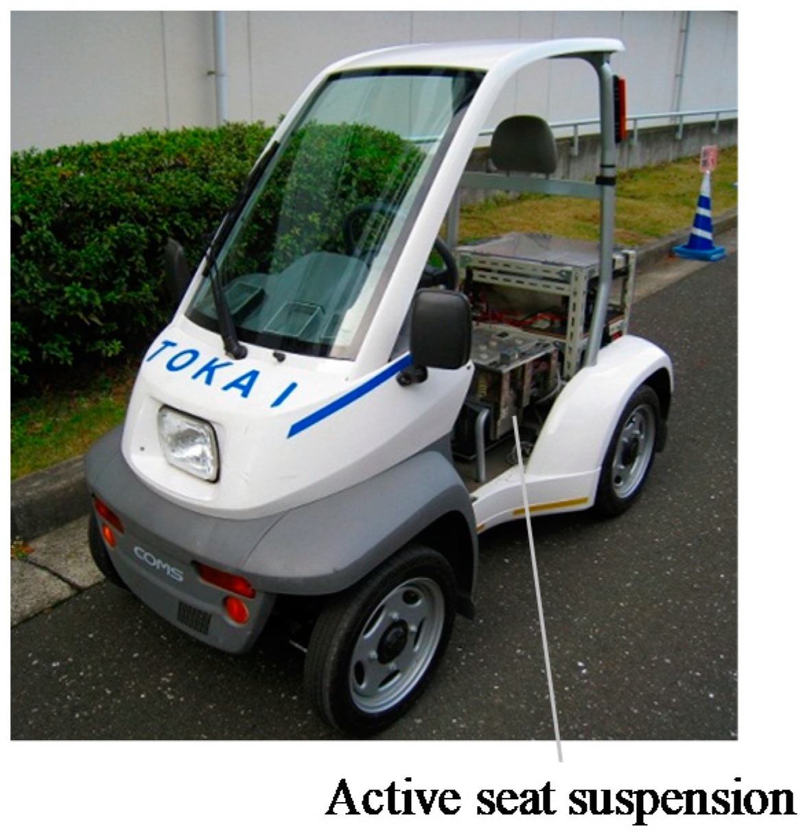
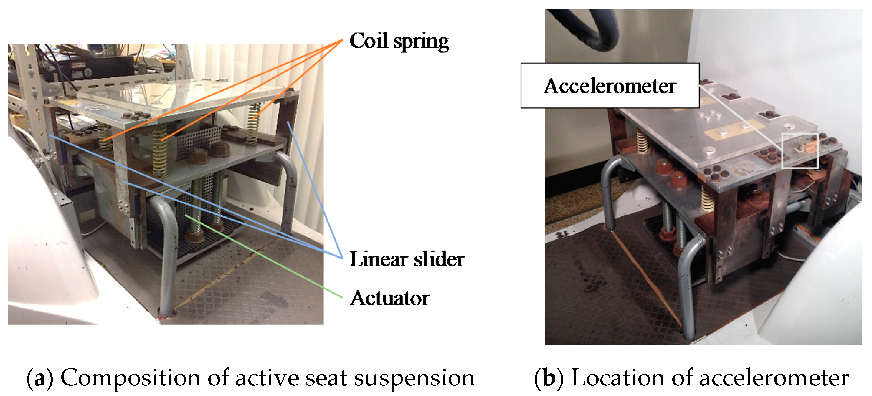
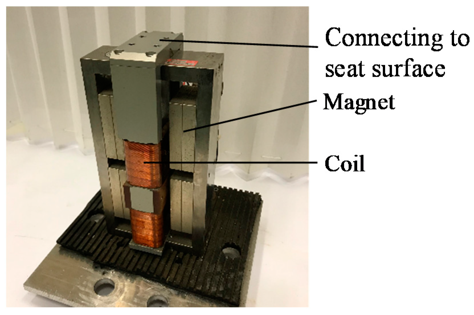
2. Active Seat Suspension
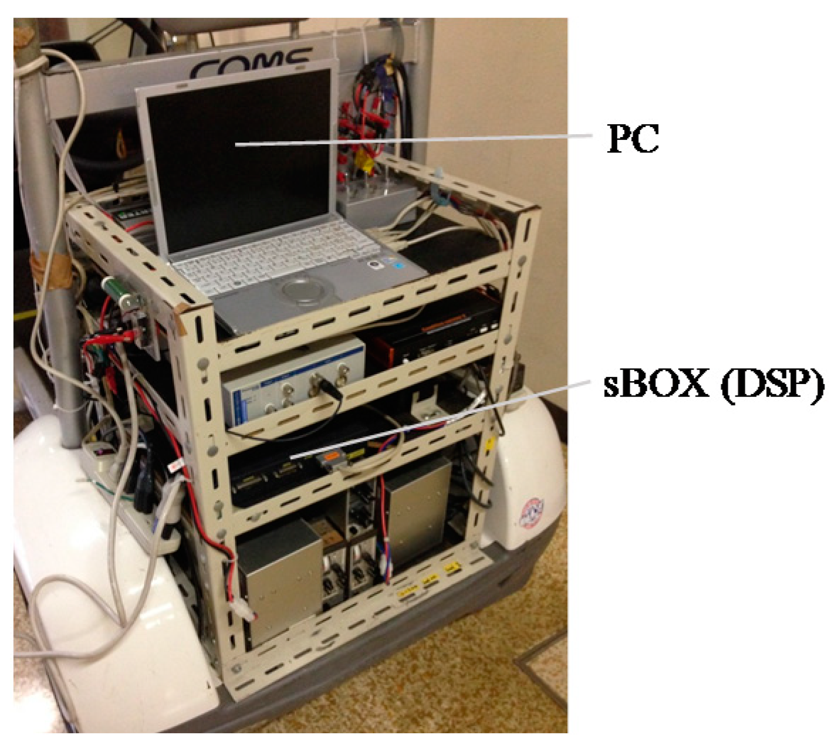
3. Modeling and Control System of Active Seat Suspension
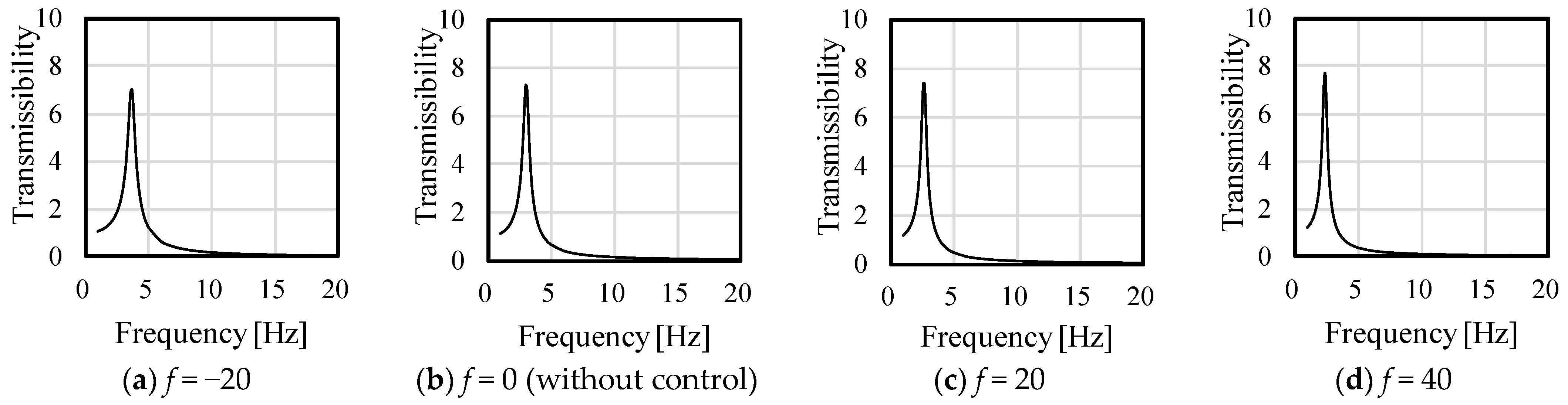
4. Frequency Characteristics of Acceleration Feedback System
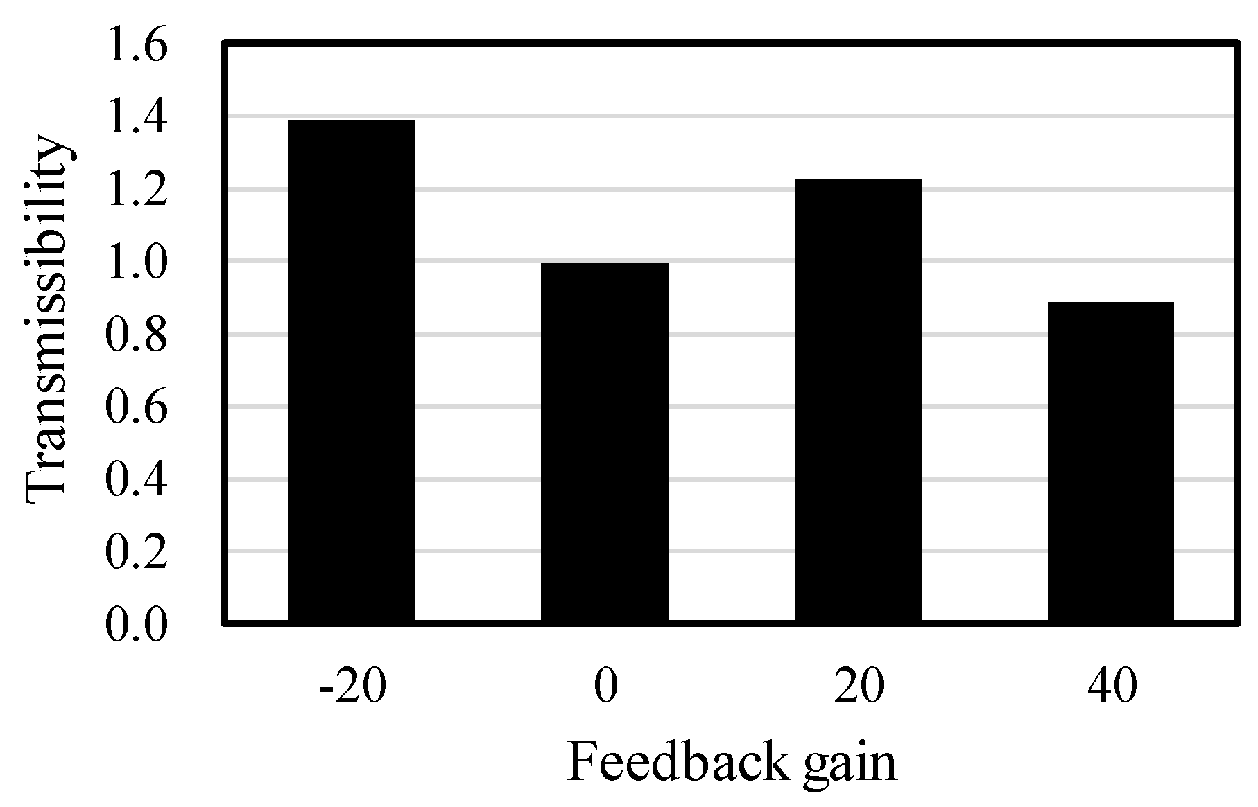
5. Effect of Control Performance by Feedback Gain
6. Conclusions
- Change of frequency characteristics affects control performance by change of resonance point.
- It is possible to suppress vibrations by applying an appropriate feedback gain. In the future, we intend to perform experiments using an actual apparatus and establish a multi-degree-of-freedom vibration control system for an actual vehicle.
Author Contributions
Funding
Data Availability Statement
Conflicts of Interest
References
- Oshinoya, Y.; Arai, H.; Ishibashi, K. Experimental Study on Active Seat Suspension for a Small Vehicle. Int. J. Appl. Math. 2004, 19, 437–443. [Google Scholar] [CrossRef]
- Ikeda, K.; Endo, A.; Minowa, R.; Narita, T.; Kato, H. Ride Comfort Control System Considering Physiological and Psychological Characteristics: Effect of Masking on Vertical Vibration on Passengers. MDPI Actuators 2018, 7, 42–54. [Google Scholar] [CrossRef] [Green Version]
- Endo, A.; Ikeda, K.; Mashino, M.; Kato, H.; Narita, T. Ride comfort control system using driver’s psychological state: Experimental consideration on heart rate variability. Int. J. Appl. Math. 2019, 59, 977–984. [Google Scholar] [CrossRef]
- Ning, D.; Sun, S.; Li, H.; Du, H.; Li, W. Active Control of an Innovative Seat Suspension System with Acceleration Measurement Based Friction Estimation. J. Sound Vib. 2016, 384, 28–44. [Google Scholar] [CrossRef]
- Ning, D.; Sun, S.; Zhang, F.; Du, H.; Li, W.; Zhang, B. Disturbance Observer Based Takagi-Sugeno Fuzzy Control for An Active Seat Suspension. Mech. Syst. Signal Process. 2017, 93, 515–530. [Google Scholar] [CrossRef] [Green Version]
- Schimmels, J.M. Improved Vibration Isolating Seat Suspension Designs Based on Position-Dependent Nonlinear Stiffness and Damping Characteristics. J. Dyn. Syst. Meas. 2003, 125, 330–338. [Google Scholar]
- Sever, M.; Yazici, H. Disturbance Observer Based Optimal Controller Design for Active Suspension Systems. IFAC Pap. 2016, 49, 105–110. [Google Scholar] [CrossRef]
- Sun, S.; Ning, D.; Yang, J.; Du, H.; Zhang, S.; Li, W. A seat Suspension with a Rotary Magnetorheological Damper for Heavy Duty Vehicles. Smart Mater. Struct. 2016, 25, 105032. [Google Scholar] [CrossRef] [Green Version]
- Zhao, Y.; Sun, W.; Gao, H. Robust Control Synthesis for Seat Suspension Systems with Actuator Saturation and Time-Varying Input Delay. J. Sound Vib. 2010, 329, 4335–4353. [Google Scholar] [CrossRef]
- Mahesh, S.L.; Pramod, D.; Shrivijay, B.P. Active Control of Uncertain Seat Suspension System Based on a State and Disturbance Observer. IEEE Trans. Syst. Man Cybern. Syst. 2020, 50, 840–850. [Google Scholar]
- Tang, X.; Ning, D.; Du, H.; Li, W.; Wen, W. Takagi-Sugeno Fuzzy Model-Based Semi-Active Control for the Seat Suspension with An Electrorheological Damper. IEEE Access 2022, 8, 98027–98037. [Google Scholar] [CrossRef]
- More, A.; Deshpande, A. A Multiple Sliding Surface Based Control for Active Seat Suspension System. In Proceedings of the 2021 5th International Conference on Intelligent Computing and Control Systems, Madurai, India, 6–8 May 2021. [Google Scholar]
- Lie, L.; Li, X. Event-Triggered Tracking Control for Active Seat Suspension Systems with Time-Varying Full-State Constraints. IEEE Trans. Syst. Man Cybern. Syst. 2022, 5, 582–590. [Google Scholar] [CrossRef]
- Taghavifar, H.; Rakheja, S. Multi-Objective Optimal Robust Seat Suspension Control of Off-Road Vehicles in the Presence of Disturbance and Parametric Uncertainty Using Metaheuristics. IEEE Trans. Intell. Veh. 2020, 5, 372–384. [Google Scholar] [CrossRef]
- Oya, M.; Harada, H.; Araki, Y. An Active Suspension Controller Achieving the Best Ride Comfort at Any Specified Location on A Vehicle. JSDD 2007, 1, 245–256. [Google Scholar] [CrossRef] [Green Version]
- Jianmin, S.; Yi, S. A Fuzzy Method Improving Vehicle Ride Comfort and Road Holding Capability. In Proceedings of the 2007 2nd IEEE Conference on Industrial Electronics and Applications, Harbin, China, 23–25 May 2007. [Google Scholar]
- Choi, H.D.; Ahn, C.K.; Shi, P.; Wu, L.; Lim, M.T. Dynamic output-feedback dissipative control for T–S fuzzy systems with time-varying input delay and output constraints. IEEE Trans. Fuzzy Syst. 2017, 25, 511–526. [Google Scholar] [CrossRef]
- Taghavifar, H.; Mardani, A.; Hu, C.; Qin, Y. Adaptive Robust Nonlinear Active Suspension Control Using an Observer-Based Modified Sliding Mode Interval ye-2 Fuzzy Neutral Network. IEEE Trans. Intell. Veh. 2020, 5, 53–62. [Google Scholar] [CrossRef]
- Rath, J.J.; Defoort, M.; Karimi, H.R.; Veluvolu, K.C. Output Feedback Active Suspension Control with Higher Order Terminal Sliding Mode. IEEE Trans. Ind. Electron. 2016, 64, 1392–1403. [Google Scholar] [CrossRef]
- Pan, H.; Jing, X.; Sun, W.; Gao, H. A Bioinspired Dynamics-Based Adaptive Tracking Control for Nonlinear Suspension Systems. IEEE Trans. Control. Syst. Technol. 2017, 26, 903–914. [Google Scholar] [CrossRef]
- Pan, H.; Sun, W.; Jing, X.; Gao, H.; Yao, J. Adaptive Tracking Control for Active Suspension Systems with Non-Ideal Actuators. J. Sound Vib. 2017, 399, 2–20. [Google Scholar] [CrossRef]
- Zhao, F.; Ge, S.S.; Tu, F.; Qin, Y.; Dong, M. Adaptive Neural Network Control for Active Suspension System with Actuator Saturation. IET Control. Theory A 2016, 10, 1696–1705. [Google Scholar] [CrossRef]
- Wenxing, L.; Haipineg, D.; Donghong, N.; Weihua, L. Robust Adaptive Sliding mode PI control for active vehicle seat suspension systems. In Proceedings of the 2019 Chinese Control and Decision Conference (CCDC), Nanchang, China, 3–5 June 2019. [Google Scholar]
- ISO 2631 1978; Guide for the Evaluation ff Human Exposure to Whole-Body Vibration. International Organization for Standardization: Geneva, Switzerland, 1978.
- Janeway, R.N. Vehicle vibration limit to fit the passenger. SAE J. 1948, 56. [Google Scholar]
- Ikeda, K.; Kuroda, J.; Uchino, D.; Ogawa, K.; Endo, A.; Kato, T.; Kato, H.; Narita, T. A Study of a Ride Comfort Control System for Ultra-Compact Vehicles Using Biometric Information. Appl. Sci. 2022, 12, 7425. [Google Scholar] [CrossRef]
- Oshinoya, Y.; Ishibashi, K.; Arai, H. Basic Examination of Improvement on Riding Comfort with An Active Seat Suspension of A Small Electric Vehicle. J. Jpn. Soc. Appl. Electromagn. Mech. 2013, 11, 209–215. (In Japanese) [Google Scholar]
- Mashino, M.; Ishida, M.; Narita, T.; Kato, H.; Yamamoto, Y. Active Seat Suspension for Ultra-Compact Electric Vehicle (Fundamental Consideration on Electrooculogram When Fall from the Bump). Int. Symp. Appl. Electromagn. Mech. 2016, 52, 215–222. [Google Scholar] [CrossRef]
- Kato, H.; Hasegawa, S.; Oshinoya, Y. Active Control of Ultra-Compact Vehicle Seat with Voice Coil Motor (Examination of the Control Performances during Driving on a Bad Road). J. Magn. Soc. Jpn. 2013, 37, 95–101. [Google Scholar] [CrossRef]


| Ultra-Compact Vehicle: EVERYDAY COMS BASIC | |
|---|---|
| (Toyota Auto Body Co., Ltd.) | |
| Total weight [kg] | 325 |
| Length [mm] | 1935 |
| Whole width [mm] | 955 |
| Height [mm] | 1600 |
| Wheelbase [mm] | 1280 |
| Tread (front, rear) [mm] | 840, 815 |
| VCM | |
| (Aoyama Special Steel Co., Ltd.) | |
| Stroke [mm] | 20 |
| Thrust constant [N/A] | 110 |
| Nominal thrust [N] | 160 |
| Maximum thrust [N] | 320 |
| Rated current [A] | 1.46 |
| Parameter | Value |
|---|---|
| Mass m [kg] | 64 |
| Damping c [Ns/m] | 145 |
| Spring k [N/m] | 23,485 |
| Feedback gain f [-] | −20, 0, 20, 40 |
| Feedback Gain f | Frequency [Hz] | Transmissibility |
|---|---|---|
| −20 | 3.7 | 6.99 |
| 0 (without control) | 3.0 | 7.27 |
| 20 | 2.6 | 7.39 |
| 40 | 2.4 | 7.68 |
Disclaimer/Publisher’s Note: The statements, opinions and data contained in all publications are solely those of the individual author(s) and contributor(s) and not of MDPI and/or the editor(s). MDPI and/or the editor(s) disclaim responsibility for any injury to people or property resulting from any ideas, methods, instructions or products referred to in the content. |
© 2022 by the authors. Licensee MDPI, Basel, Switzerland. This article is an open access article distributed under the terms and conditions of the Creative Commons Attribution (CC BY) license (https://creativecommons.org/licenses/by/4.0/).
Share and Cite
Ikeda, K.; Kuroda, J.; Uchino, D.; Ogawa, K.; Endo, A.; Kato, T.; Kato, H.; Narita, T. Vibration Characteristics Control of Resonance Point in Vehicle: Fundamental Considerations of Control System without Displacement and Velocity Information. Vibration 2023, 6, 1-10. https://doi.org/10.3390/vibration6010001
Ikeda K, Kuroda J, Uchino D, Ogawa K, Endo A, Kato T, Kato H, Narita T. Vibration Characteristics Control of Resonance Point in Vehicle: Fundamental Considerations of Control System without Displacement and Velocity Information. Vibration. 2023; 6(1):1-10. https://doi.org/10.3390/vibration6010001
Chicago/Turabian StyleIkeda, Keigo, Jumpei Kuroda, Daigo Uchino, Kazuki Ogawa, Ayato Endo, Taro Kato, Hideaki Kato, and Takayoshi Narita. 2023. "Vibration Characteristics Control of Resonance Point in Vehicle: Fundamental Considerations of Control System without Displacement and Velocity Information" Vibration 6, no. 1: 1-10. https://doi.org/10.3390/vibration6010001