
Numerical Study on Coupled Smoke Control Using Longitudinal Ventilation and Naturally Ventilated Shafts during Fires in a Road Tunnel

Abstract
:1. Introduction
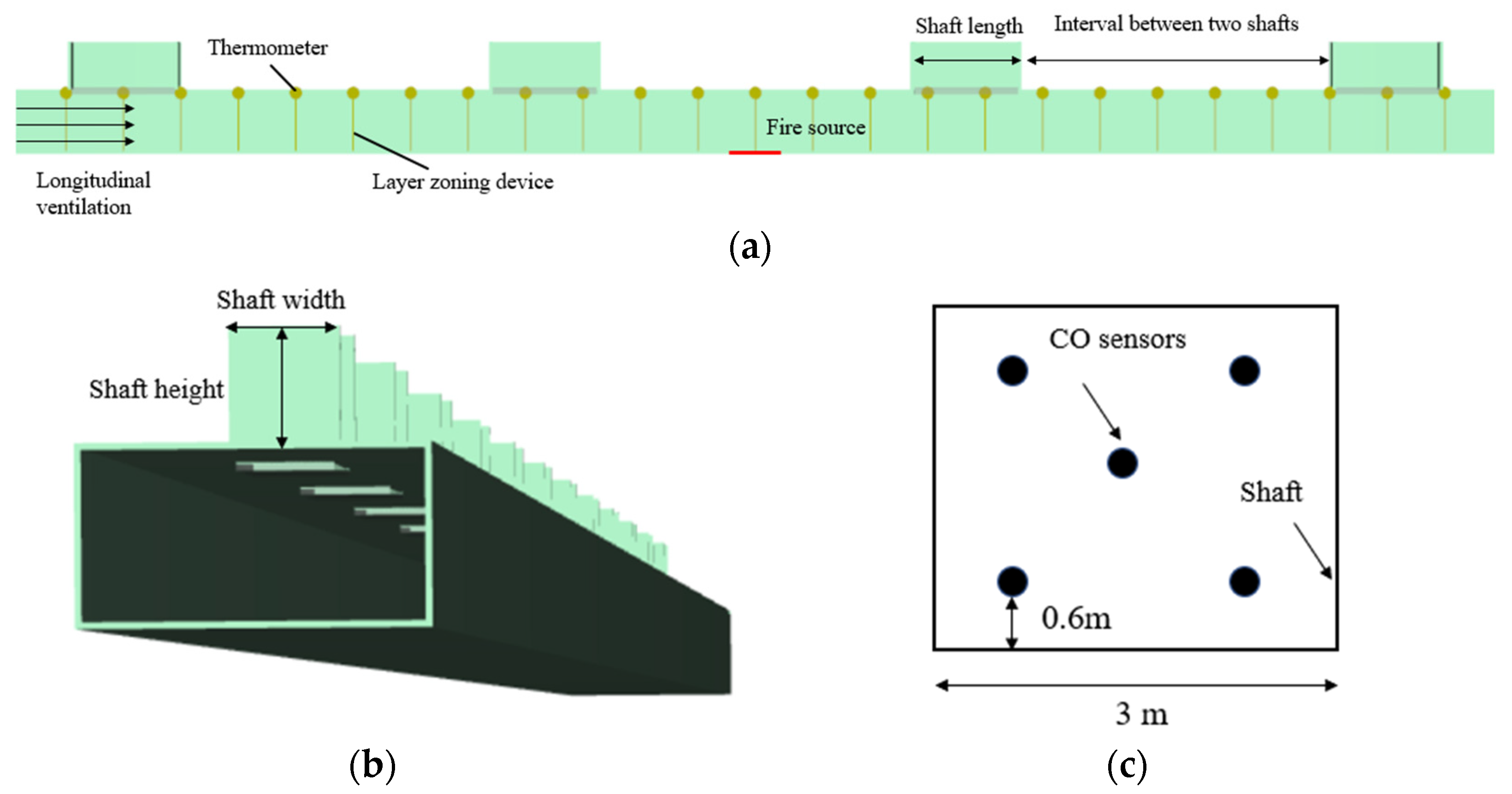
2. Numerical Modeling
2.1. Fire Scenarios
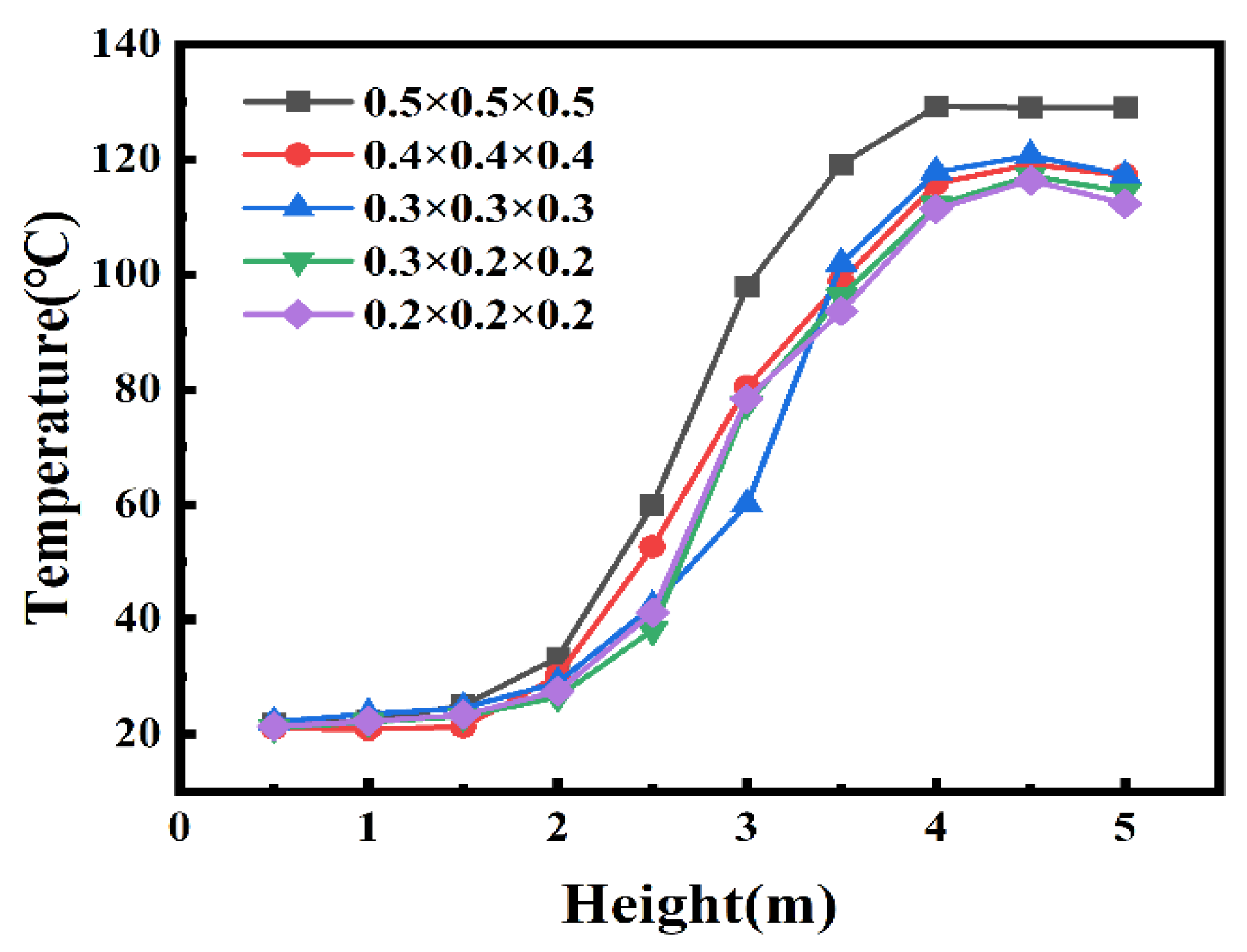
2.2. Meshes
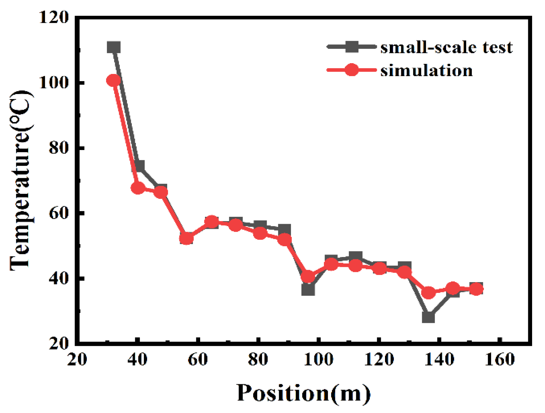
2.3. Verification of FDS Modelling
3. Results
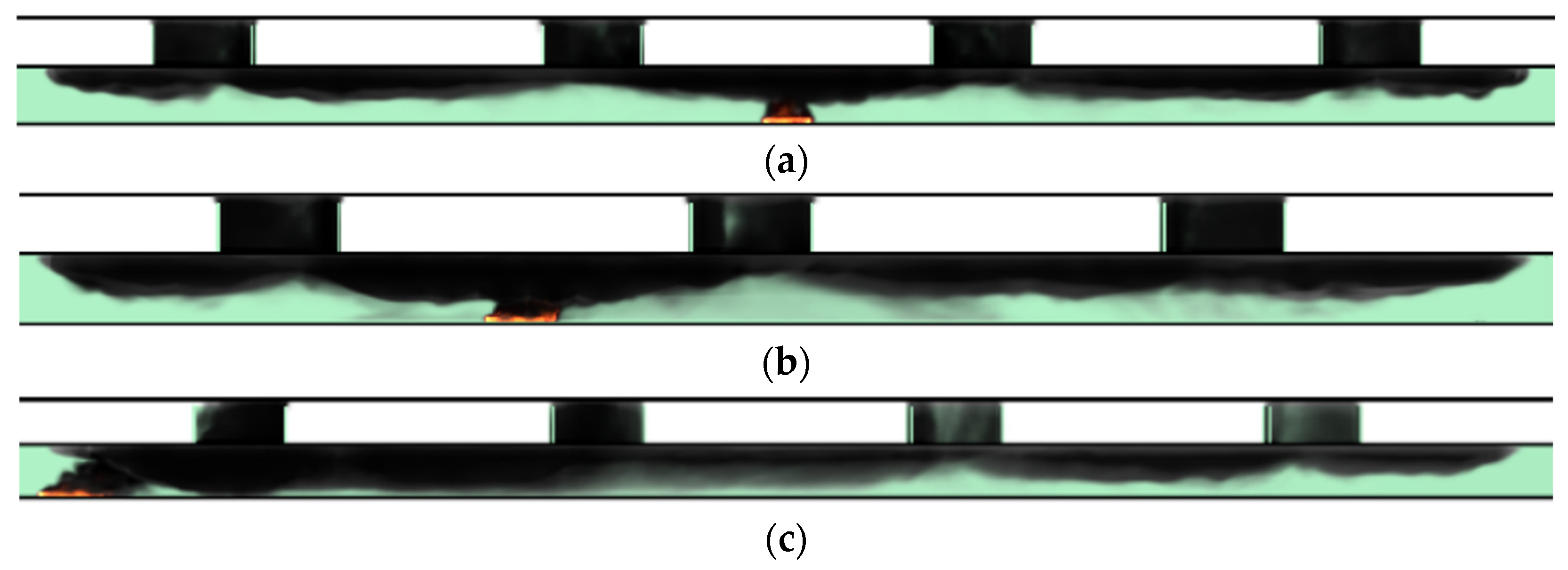
3.1. Smoke Movement Behavior
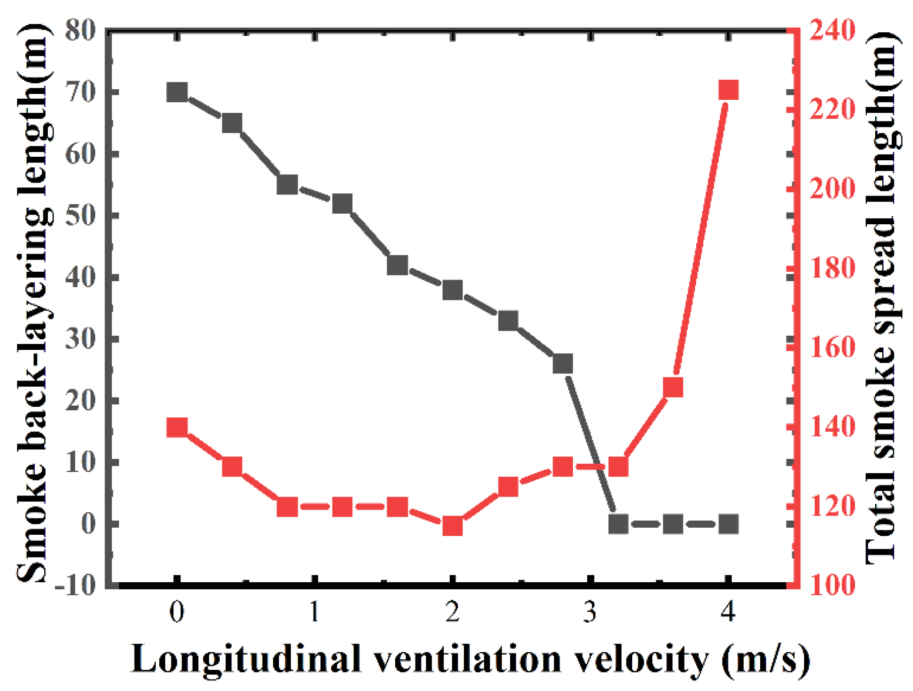
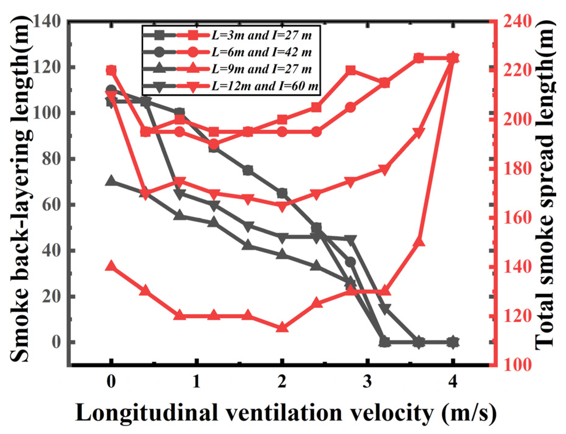
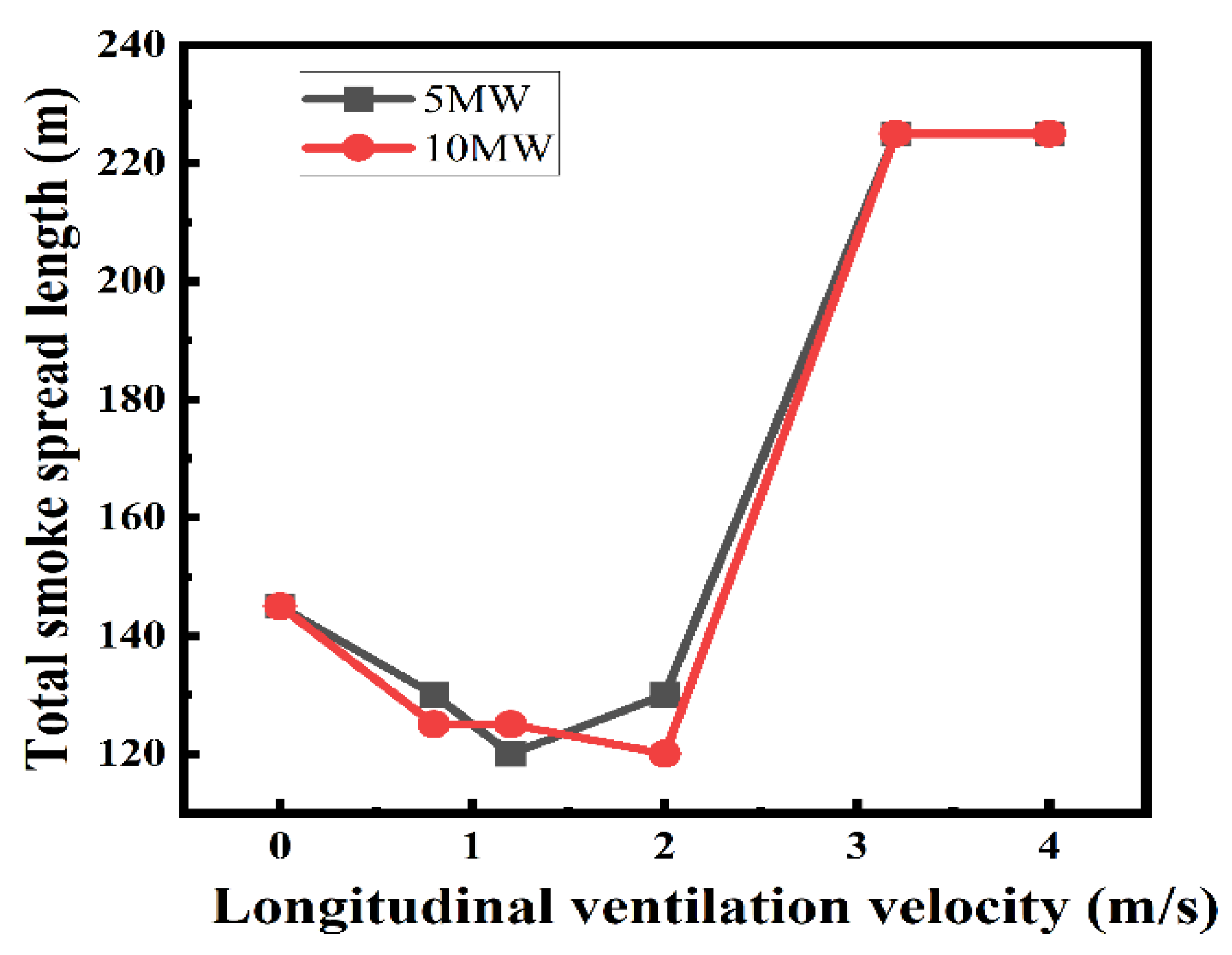
3.1.1. Smoke Spread Length
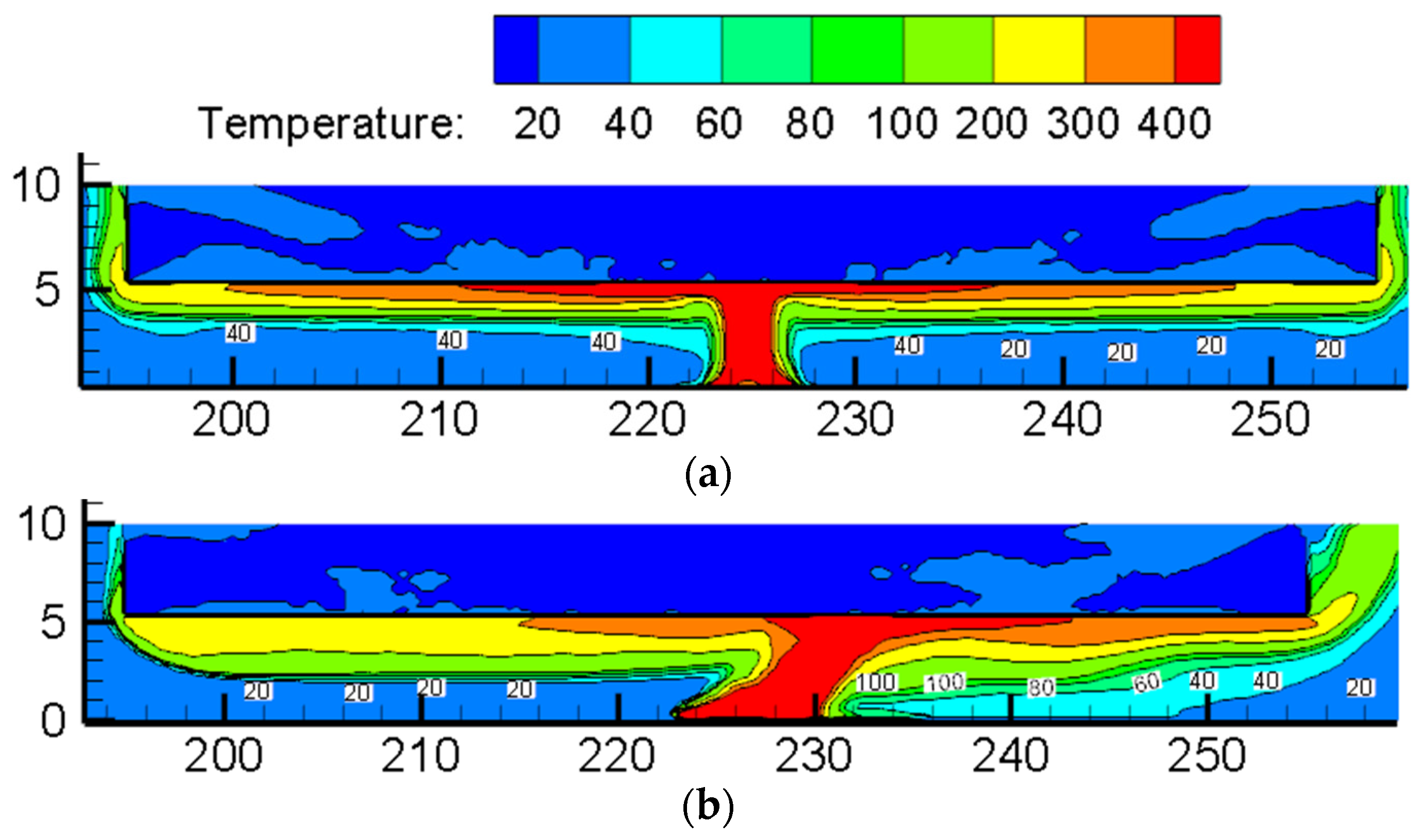
3.1.2. Smoke Temperature at Human Height
3.2. Smoke Exhaust Performance
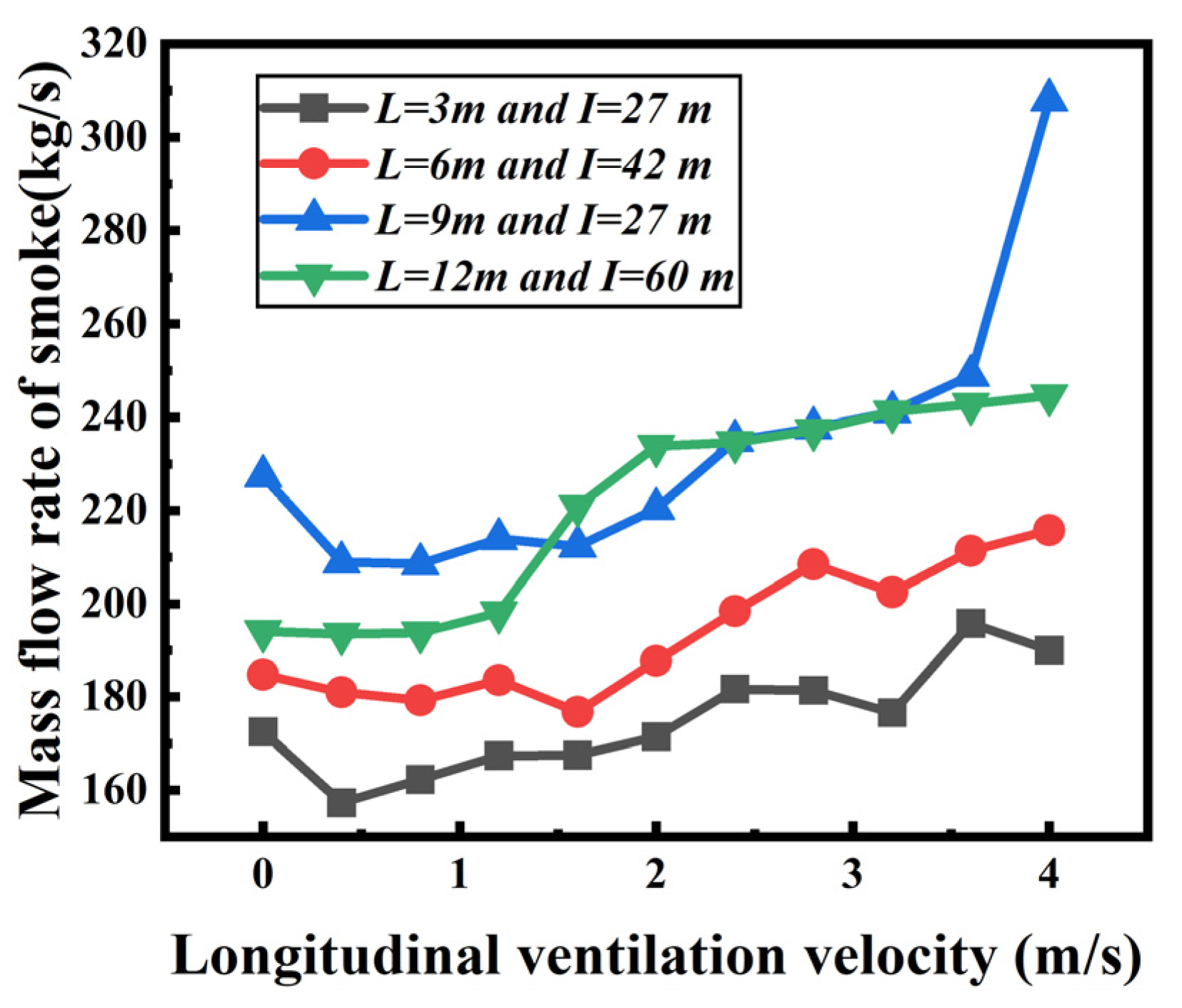
3.2.1. Mass Flow Rate of Smoke Exhaust through Shaft
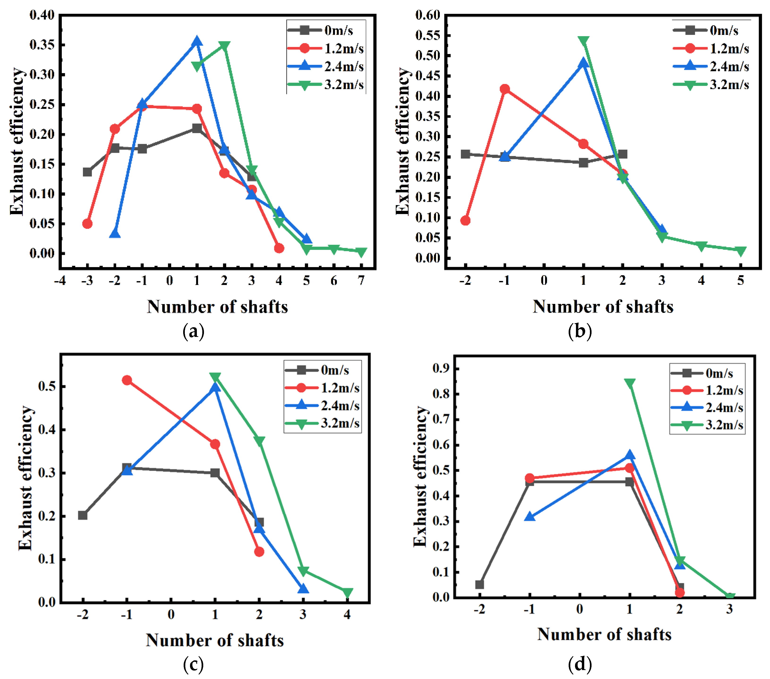
3.2.2. Smoke Exhaust Efficiency
4. Conclusions
- (1)
- With the increase in longitudinal ventilation velocity, the total smoke spread length firstly decreases (V < 1 m/s) and then keeps almost constant (1 m/s < V < 2 m/s), fi-nally increasing significantly (V > 2 m/s).
- (2)
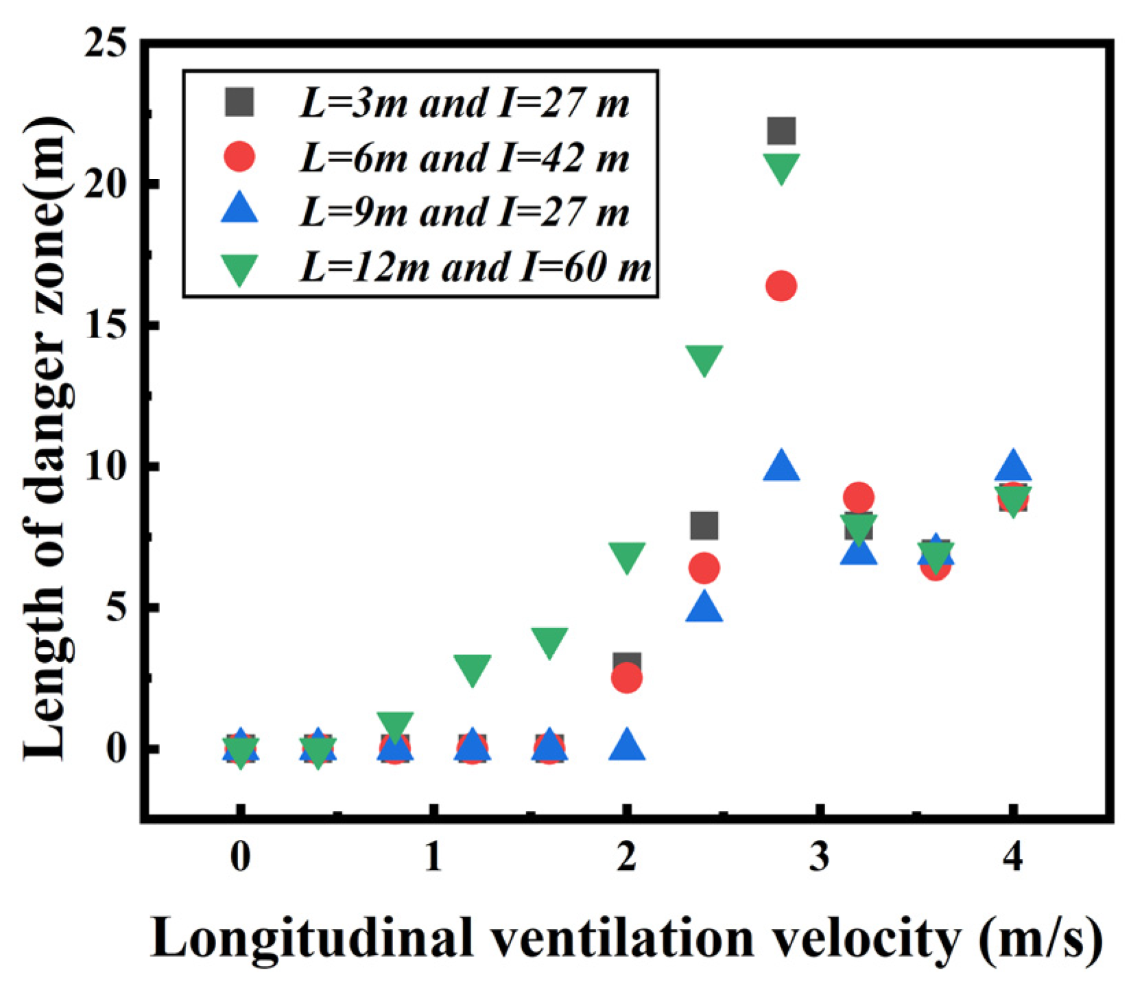
- The length of the dangerous area (over 60 °C) at human height is basically 0 for all cases (except for Scenario 4 of shaft arrangement) when the longitudinal ventilation velocity is less than 2 m/s.
- (3)
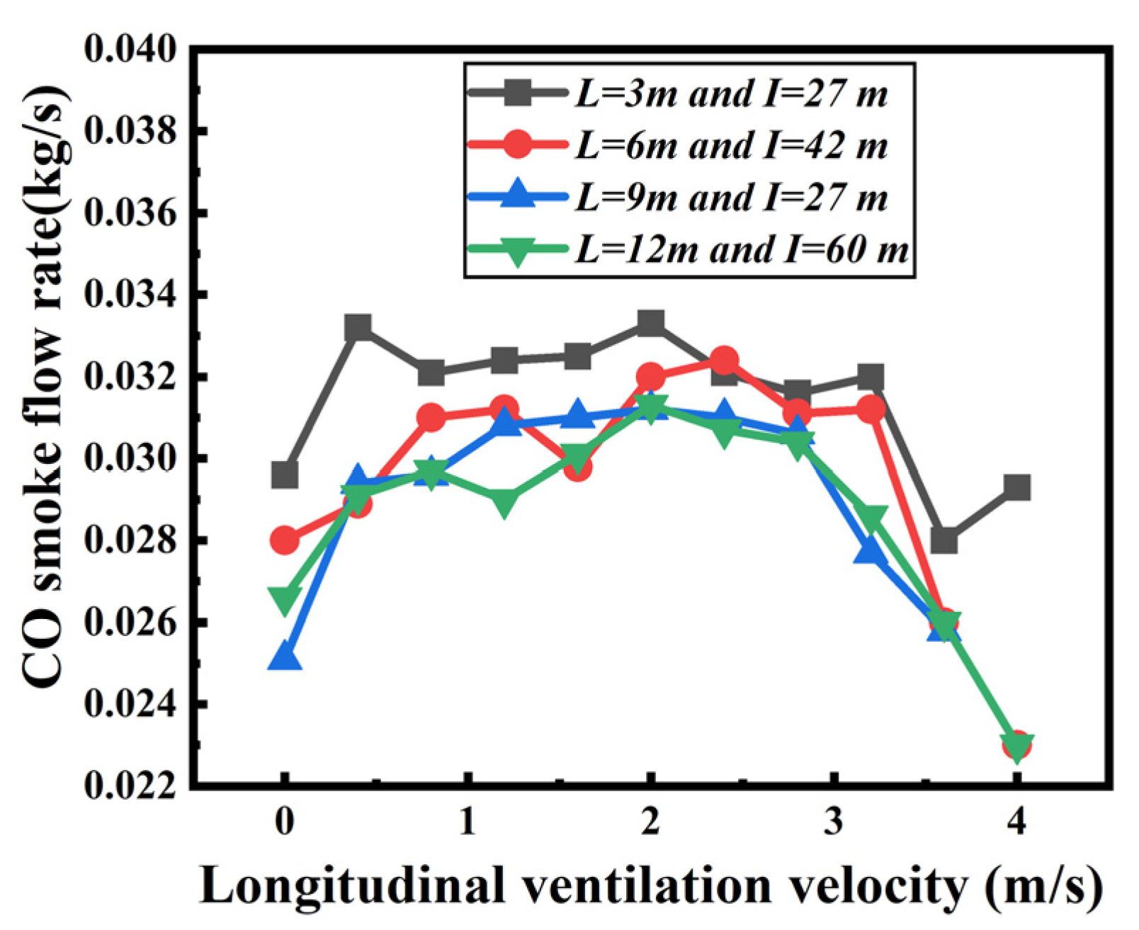
- The CO smoke flow rate through the shaft is relatively high when the longitudinal ventilation velocity is within the range of 1–2 m/s for 4 kinds of shaft arrangement scenarios.
Author Contributions
Funding
Institutional Review Board Statement
Informed Consent Statement
Data Availability Statement
Acknowledgments
Conflicts of Interest
References
- Ji, J.; Gao, Z.H.; Fan, C.G.; Sun, J.H. Large Eddy Simulation of stack effect on natural smoke exhausting effect in urban road tunnel fires. Int. J. Heat Mass Transf. 2013, 66, 531–542. [Google Scholar] [CrossRef]
- Yao, Y.Z.; Qu, B.L.; Zhu, H.Q.; Wang, J.X.; Zhao, S.Z.; Wang, Q. Theoretical and numerical study on critical velocity and driving force for preventing smoke backlayering in a connection roadway fire of coal mines. Tunn. Undergr. Space Technol. 2022, 127, 104566. [Google Scholar] [CrossRef]
- Wang, M.N.; Guo, X.H.; Ni, G.B.; Yu, L.; Li, C.H. A Discussion on the Control Standards for Smoke CO Concentration during Fires in High-altitude Railway Tunnels. Mod. Tunn. Technol. 2022, 59, 40–45. [Google Scholar]
- Hu, L.H. Studies on Thermal Physics of Smoke Movement in Tunnel Fires. Ph.D. Thesis, University of Science and Technology of China, Hefei, China, 2006. [Google Scholar]
- Wu, Y.; Bakar, M. Control of smoke flow in tunnel fires using longitudinal ventilation systems—A study of the critical velocity. Fire Saf. J. 2000, 35, 363–390. [Google Scholar] [CrossRef]
- Ingason, H.; Li, Y.Z. Model scale tunnel fire tests with longitudinal ventilation. Fire Saf. J. 2010, 45, 371–384. [Google Scholar] [CrossRef]
- Zhong, W.; Lv, J.J.; Li, Z.Z.; Liang, T.S. A study of bifurcation flow of fire smoke in tunnel with longitudinal ventilation. Int. J. Heat Mass Transf. 2013, 67, 829–835. [Google Scholar] [CrossRef]
- Sung, R.L.; Hong, R. An Experimental Study of the Effect of the Aspect Ratio on the Critical Velocity in Longitudinal Ventilation Tunnel Fires. J. Fire Sci. 2005, 23, 119–138. [Google Scholar]
- Xu, Z.S.; Li, D.J.; Xue, P.; Zhao, H.L. Study on Fire Temperature Field Distribution in Longitudinal Ventilation Tunnel. China Saf. Sci. J. 2010, 20, 51–56. [Google Scholar]
- Yao, Y.Z.; Zhang, Y.; Zhu, H.Q.; Han, Z.Q. Effects of ambient pressure on characteristics of smoke movement in tunnel fires. Tunn. Undergr. Space Technol. 2023, 134, 104981. [Google Scholar] [CrossRef]
- Newman, J.S. Experimental evaluation of fire-induced stratification. Combust. Flame 1984, 57, 33–39. [Google Scholar] [CrossRef]
- Wang, Y.F.; Yan, P.N.; Zhang, B.; Jiang, J.C. Thermal buoyant smoke back-layering length in a naturally ventilated tunnel with vertical shafts. Appl. Therm. Eng. 2016, 93, 947–957. [Google Scholar] [CrossRef]
- Yao, Y.Z.; Li, Y.Z.; Ingason, H.; Cheng, X. Numerical study on overall smoke control using naturally ventilated shafts during fires in a road tunnel. Int. J. Therm. Sci. 2019, 140, 491–504. [Google Scholar] [CrossRef]
- Fan, C.G.; Ji, J.; Wang, W.; Sun, J.H. Effects of vertical shaft arrangement on natural ventilation performance during tunnel fires. Int. J. Heat Mass Transf. 2014, 73, 158–169. [Google Scholar] [CrossRef]
- Yuan, Z.; Lei, B.; Kashef, A. Experimental and Theoretical Study for Tunnel Fires with Natural Ventilation. Fire Technol. 2013, 51, 691–706. [Google Scholar] [CrossRef]
- Wang, M.N.; Guo, X.H.; Yu, L.; Zhang, Y.T.; Tian, Y. Experimental and numerical studies on the smoke extraction strategies by longitudinal ventilation with shafts during tunnel fire. Tunn. Undergr. Space Technol. 2021, 116, 1034030. [Google Scholar] [CrossRef]
- Zhong, W.; Fan, C.G.; Ji, J.; Yang, J.P. Influence of longitudinal wind on natural ventilation with vertical shaft in a road tunnel fire. Int. J. Heat Mass Transf. 2013, 57, 671–678. [Google Scholar] [CrossRef]
- Tong, Y.; Shi, M.H.; Gong, Y.F.; He, J.P. Full-scale experimental study on smoke flow in natural ventilation road tunnel fires with shafts. Tunn. Undergr. Space Technol. 2009, 24, 627–633. [Google Scholar]
- Guo, Q.H.; Zhu, H.H.; Zhang, Y.; Yan, Z.G. Theoretical and experimental studies on the fire-induced smoke flow in naturally ventilated tunnels with large cross-sectional vertical shafts. Tunn. Undergr. Space Technol. 2020, 99, 103359. [Google Scholar] [CrossRef]
- Yao, Y.Z.; Zhang, S.G.; Shi, L.; Cheng, X.D. Effects of shaft inclination angle on the capacity of smoke exhaust under tunnel fire. Indoor Built Environ. 2019, 28, 77–87. [Google Scholar] [CrossRef]
- Huang, Y.B.; Li, Y.F.; Dong, B.Y.; Li, J.M.; Liang, Q. Numerical investigation on the maximum ceiling temperature and longitudinal decay in a sealing tunnel fire. Tunn. Undergr. Space Technol. 2018, 72, 120–130. [Google Scholar] [CrossRef]
- Jae, S.R.; Hong, S.R.; Dong, H.K.; Woo, S.J.; Yong, J.J. Critical velocity and burning rate in pool fire during longitudinal ventilation. Tunn. Undergr. Space Technol. 2007, 22, 262–271. [Google Scholar]
- Gannouni, S.; Maad, R. Numerical study of the effect of blockage on critical velocity and backlayering length in longitudinally ventilated tunnel fires. Tunn. Undergr. Space Technol. 2015, 48, 147–155. [Google Scholar] [CrossRef]
- Weng, M.C.; Lu, X.L.; Liu, F.; Shi, X.P.; Yu, L.X. Prediction of backlayering length and critical velocity in metro tunnel fires. Tunn. Undergr. Space Technol. 2015, 47, 64–72. [Google Scholar] [CrossRef]
- Liu, B.; Mao, J.; Xi, Y.H.; Hu, J.W. Effects of altitude on smoke movement velocity and longitudinal temperature distribution in tunnel fires. Tunn. Undergr. Space Technol. 2021, 112, 103850. [Google Scholar] [CrossRef]
- Tong, Y.; Zhai, J.; Wang, C.; Zhou, B.; Niu, X. Possibility of using roof openings for natural ventilation in a shallow urban road tunnel. Tunn. Undergr. Space Technol. 2016, 54, 92–101. [Google Scholar] [CrossRef]
- Ministry of Development. CJJ75-97, Code for Planting Planning and Design on Urban Road; China Architecture and Building Press: Beijing, China, 1997.
- Fan, C.G.; Zhang, L.; Jiao, S.C.; Yang, Z.W.; Li, M.H.; Liu, X.P. Smoke spread characteristics inside a tunnel with natural ventilation under a strong environmental wind. Tunn. Undergr. Space Technol. 2018, 82, 99–110. [Google Scholar] [CrossRef]
- Mcgrattan, K.B.; Hostikka, S.; Floyd, J.E. Fire Dynamics Simulator (Version 5): User’s Guide; NIST Special Publications: Gaithersburg, MD, USA, 2010; Volume 4, pp. 206–207. [Google Scholar]
- Zhao, S.Z.; Li, Y.Z.; Ingason, H.; Liu, F. A theoretical and experimental study on the buoyancy-driven smoke flow in a tunnel with vertical shafts. Int. J. Therm. Sci. 2019, 141, 33–46. [Google Scholar] [CrossRef]
- Ura, F.; Kawabata, N.; Tanaka, F. Characteristics of smoke extraction by natural ventilation during a fire in a shallow urban road tunnel with roof openings. Fire Saf. J. 2014, 67, 96–106. [Google Scholar] [CrossRef]
- Gehandler, J.; Eymann, L.; Regeffe, M. Limit-Based Fire Hazard Model for Evaluating Tunnel Life Safety. Fire Technol. 2015, 51, 585–614. [Google Scholar] [CrossRef]


| Test No. | Shaft Length (m) | Longitudinal Ventilation Velocity (m/s) | Shaft Interval (m) | Heat Release Rate (MW) |
|---|---|---|---|---|
| 1–11 | 3 | 0–4 | 27 | 30 |
| 12–22 | 6 | 42 | ||
| 23–33 | 9 | 27 | ||
| 34–44 | 12 | 60 | 5, 10 | |
| 45–52 | 9 | 0.8, 2, 3.2, 4 | 27 | |
| 53–63 | Without shaft | 0–4 | - | 30 |
Disclaimer/Publisher’s Note: The statements, opinions and data contained in all publications are solely those of the individual author(s) and contributor(s) and not of MDPI and/or the editor(s). MDPI and/or the editor(s) disclaim responsibility for any injury to people or property resulting from any ideas, methods, instructions or products referred to in the content. |
© 2023 by the authors. Licensee MDPI, Basel, Switzerland. This article is an open access article distributed under the terms and conditions of the Creative Commons Attribution (CC BY) license (https://creativecommons.org/licenses/by/4.0/).
Share and Cite
Yao, Y.; Wang, Y.; Chen, L.; Ren, F.; Shi, C. Numerical Study on Coupled Smoke Control Using Longitudinal Ventilation and Naturally Ventilated Shafts during Fires in a Road Tunnel. Fire 2023, 6, 126. https://doi.org/10.3390/fire6030126
Yao Y, Wang Y, Chen L, Ren F, Shi C. Numerical Study on Coupled Smoke Control Using Longitudinal Ventilation and Naturally Ventilated Shafts during Fires in a Road Tunnel. Fire. 2023; 6(3):126. https://doi.org/10.3390/fire6030126
Chicago/Turabian StyleYao, Yongzheng, Yintong Wang, Liang Chen, Fei Ren, and Congling Shi. 2023. "Numerical Study on Coupled Smoke Control Using Longitudinal Ventilation and Naturally Ventilated Shafts during Fires in a Road Tunnel" Fire 6, no. 3: 126. https://doi.org/10.3390/fire6030126