Article

Characteristics of Double-Layer, Large-Flow Dielectric Barrier Discharge Plasma Source for Toluene Decomposition

Laboratory for Future Interdisciplinary Research of Science and Technology, Tokyo Institute of Technology, J2-32, 4259 Nagatsuta, Midori-ku, Yokohama 226-8502, Japan
*
Authors to whom correspondence should be addressed.
Plasma 2023, 6(2), 212-224; https://doi.org/10.3390/plasma6020016
Submission received: 25 February 2023 / Revised: 26 March 2023 / Accepted: 28 March 2023 / Published: 3 April 2023
(This article belongs to the Special Issue Feature Papers in Plasma Sciences 2023)

Abstract

:
The direct decomposition of toluene-containing humidified air at large flow rates was studied in two types of reactors with dielectric barrier discharge (DBD) features in ambient conditions. A scalable large-flow DBD reactor (single-layer reactor) was designed to verify the feasibility of large-flow plasma generation and evaluate its decomposition characteristics with toluene-containing humidified air, which have not been investigated. In addition, another large-flow DBD reactor with a multilayer structure (two-layer reactor) was developed as an upscale version of the single-layer reactor, and the scalability and superiority of the features of the multilayer structure were validated by comparing the decomposition characteristics of the two reactors. Consequently, the large-flow DBD reactor showed similar decomposition characteristics to those of the small-flow DBD reactor regarding applied voltage, flow velocity, flow rate, and discharge length, thus justifying the feasibility of large-flow plasma generation. Additionally, the two-layer reactor is more effective than the single-layer reactor, suggesting multilayer configuration is a viable scheme for further upscaled DBD systems. A high decomposition rate of 59.5% was achieved at the considerably large flow rate of 110 L/min. The results provide fundamental data and present guidelines for the implementation of the DBD plasma-based system as a solution for volatile organic compound abatement.

1. Introduction

Volatile organic compounds (VOCs), which comprise a staple of air pollutants, are emitted in various industrial sectors. The main sources of VOCs include the extraction of petroleum and natural gas, combustion of fossil fuels, and the manufacturing of lubricants, adhesives, paints, oil derivatives, and paint coatings. Among these, the paint-coating industry accounts for approximately 50% of all VOC emissions in urban areas [1,2]. The emissions of VOCs in the atmosphere can cause environmental problems and present a major risk to human health. Therefore, the minimization of the adverse impacts of VOCs on public health and air quality improvement is a major concern. The typical measures enforced to process VOCs include adsorption by liquids and activated carbon, as well as combustion by fuels, biofilters, and catalytic oxidation [3,4]. However, these methods are associated with various limitations, such as large energy consumption, production of undesirable by-products in catalytic oxidation, and high running absorption costs.
Decomposition through nonthermal plasma (NTP) technology, also referred to as low-temperature atmospheric plasma, provides a promising option for VOC treatment due to its various advantages, e.g., low energy consumption, high decomposition efficiency, and ease of operation [4,5,6,7,8,9]. Additionally, because NTP can be generated at temperatures as low as room temperature and possesses abundant reactive species (e.g., OH, O, O3, and N in air plasma), it is also utilized in numerous fields, which include disinfection, medicine, chemical analysis, and surface modification, in different forms [10,11,12,13,14]. For example, Kurosawa et al. and Nomura et al. [15,16] reported the effect of NTP on hemostasis in the form of a plasma jet in medicine. Moreover, NTP exhibited its enhancement effect on the coating of polydopamine on a graphite substrate as well as its conducive influence on protein introduction into plant cells and surface modification [17,18]. Conversely, NTP has been proven to cause deconstructive phenomena on biological cells, e.g., bactericidal effect and DNA damage [19,20]. Among them, dielectric barrier discharge (DBD) plasma is considered the most suitable form for the decomposition of VOCs and has gained considerable attention in the scientific and industrial fields [21,22]. DBD has the following strengths. First, a homogeneous bulk plasma volume can be generated with stable plasma, which enables the gas to be treated uniformly. Moreover, in comparison with other NTPs, DBD exhibits better effectiveness and consumes less energy [23]. Consequently, DBD has become the mainstream for the configuration of processing systems for different VOC decompositions by focusing on single VOC abatement, e.g., toluene, benzene, and formaldehyde. The configurations of the DBD systems can be mainly divided into three types: planar, coaxial, and surface types, and were well described by Kogelschatz and Pemen et al. [5,23,24]. Meanwhile, they can also be categorized into standalone DBD and DBD catalysis systems in terms of the presence or absence of a catalyst, as the characteristics of DBD systems may be considerably influenced when combined with catalysts [4]. Based on the use of various techniques to adjust parameters (e.g., configuration, geometric features, catalyst incorporation, etc.), it has been proven that the DBD system is an effective and efficient technology for reducing VOCs [3]. Nevertheless, almost all of these efforts were concentrated on the lab scale at small flow rates, and the processing capability was restricted to low gas flow rates (less than a few L/min) [25]. Moreover, all the characterizations and optimizations were also performed on the lab scale, which is far from practical for industrial applications. Therefore, there is strong demand to investigate the characteristics of DBD systems for VOC decomposition at large flow rates that are more practical in the fields of building ventilation, industrial effluents, etc.
In this study, a scalable DBD reactor (single-layer reactor) capable of treating gases at flow rates that are two orders of magnitude larger than small-flow DBD reactors (typically less than 1 L/min) was developed for VOC abatement, and it was characterized at large flow rates. Additionally, another large-flow, multilayer (two-layer) DBD reactor was developed based on the single-layer reactor to verify its scalability and superiority. Using the two reactors, the decomposition performance of toluene treatment was analyzed in large-flow scales, including the decomposition rate and energy efficiency at different applied voltages (15–21.5 kV), flow velocities (1–4.48 m/s), flow rates (10–110 L/min), and discharge lengths (300–500 mm). Thus, the feasibility of the configuration of large-flow DBD reactors was also verified. Furthermore, by comparing the decomposition performances of the two reactors in different conditions, the feasibility and superiority of the multilayer structure in the large-flow DBD reactor configurations (intended for use for VOC abatement) are demonstrated. Based on the findings, an upscale multilayer reactor will be constructed in the near future.

2. Materials and Methods

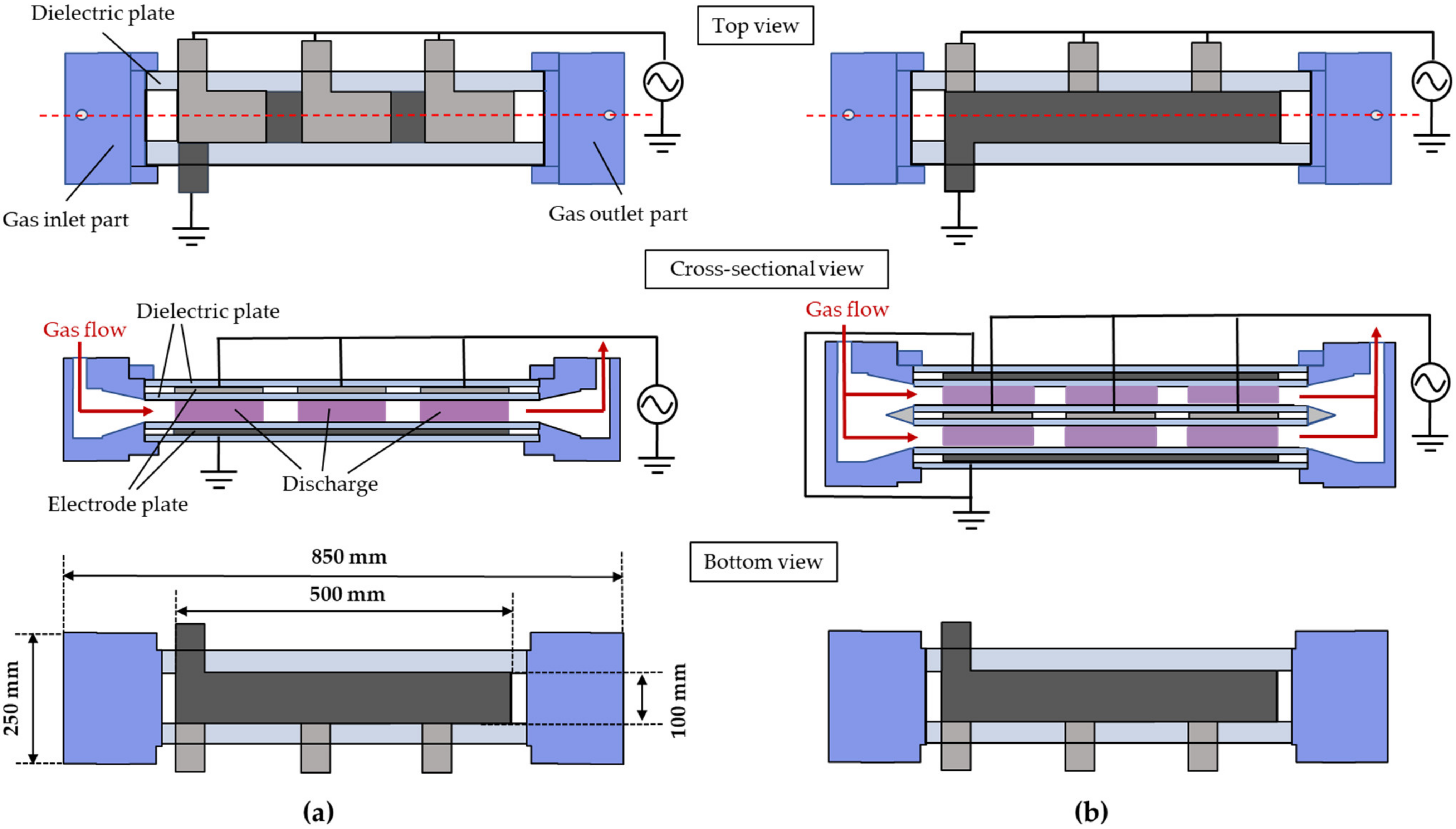
2.1. Large-Flow DBD Reactors: Scalable Single-Layer and Two-Layer Types

Two types of large-flow DBD reactors were designed and fabricated, i.e., the scalable type (single-layer reactor) and the multilayer type (two-layer reactor), which comprise a discharge gap with a thickness of 2 mm. The details of the two reactors are presented in Figure 1. The single-layer reactor consists of three components rendered using different colors: gas inlet (blue), gas outlet (blue), and the decomposition part in between; the system is 850 mm long and 250 mm wide, as shown in the upper part of Figure 1a.
The gas inlet and outlet part were made of acrylic resin. In addition, the gas inlet and outlet part also serve as buffer channels, thus enabling the passage of the gas through the decomposition part uniformly. In the decomposition part, i.e., the plasma zone, one Al plate (length 500 mm, width 100 mm, and thickness 2 mm) and three smaller Al plates (length 150 mm, width 100 mm, thickness 2 mm) serve as the ground and high-voltage electrodes, where the electrodes are covered by four glass plates (length 600 mm, width 200 mm, and thickness 2 mm) on both sides, thus acting as insulating dielectrics (κ= 7–7.5). Between the glass-covered electrodes, polytetrafluoroethylene sheets (length 600 mm, width 50 mm, and thickness 2 mm) are inserted as spacers to form a discharge space of 90 cm3, as shown in the cross-sectional view in the center of Figure 1a. Based on the single-layer reactor, one more electrode layer is stacked on top to configure a two-layer reactor (multilayer type) with a discharge zone that is twice as large as that of the single-layer reactor, thus realizing a discharge space of 180 cm3. The cross-sectional view shown in the center of Figure 1b indicates the formation of two flow paths. When a high AC voltage is applied on the electrodes (e.g., generally several kV), a uniform plasma discharge can be observed in the discharge zone as depicted in the cross-sectional views in Figure 1.

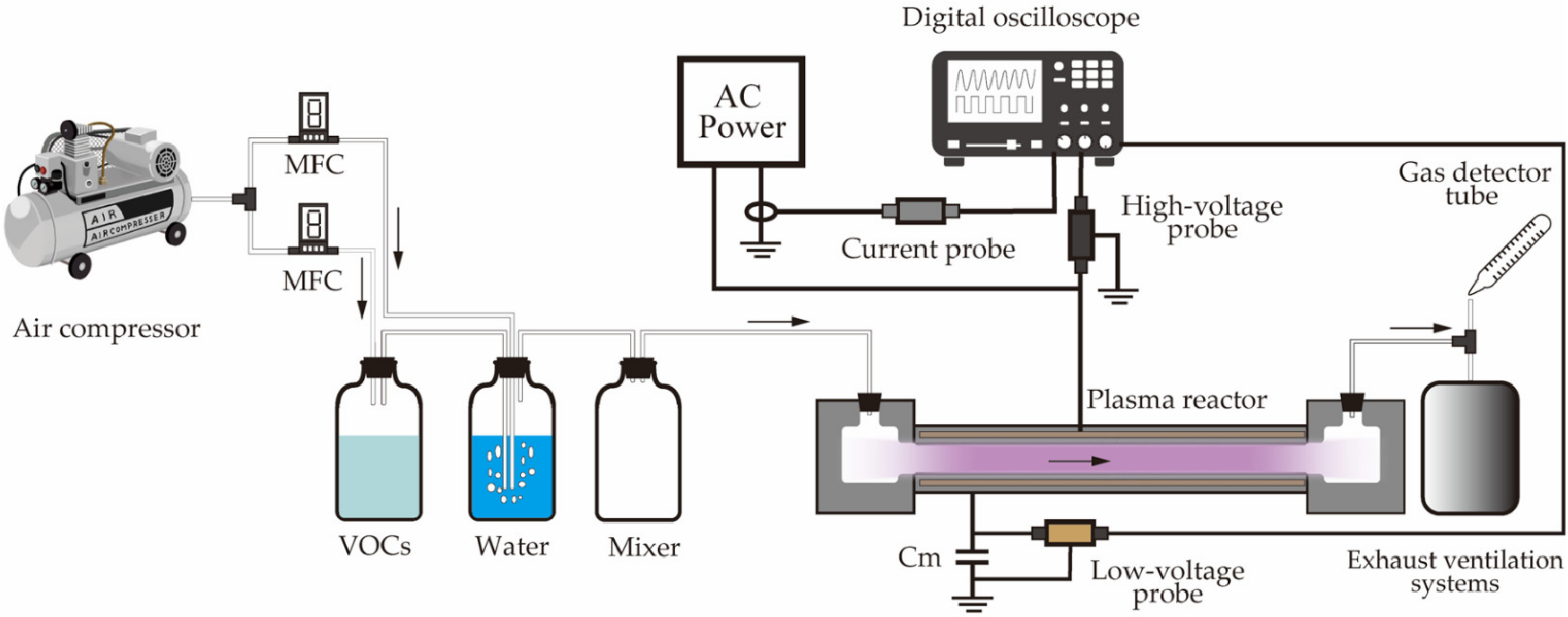
2.2. Experimental Setup

The experimental setup is shown in Figure 2. There are four main components: a gas-mixing system, an alternating current (AC) power supply, large-flow DBD reactors, and analytical instruments. The flow of evaporated toluene in the container is achieved by mixing the toluene in water and diluting it using compressed air to emulate humidified toluene-mixed air. A mass-flow controller (MFC, Japan Star Techno, Osaka, Japan) was used to adjust the concentration of the toluene by modifying the ratio of the gas flow rates between the toluene and compressed air. The toluene concentrations before and after the treatment were determined using a gas detector tube (Toluene, No. 122, Gastec Corporation, Ayase, Japan) at the outlet of the large-flow DBD reactor. The large-flow DBD reactor was energized by using a 50 Hz AC power source (rated voltage 0–22 kV). Additionally, an energy meter (TAP-TST8N, Sanwa Supply Inc., Okayama, Japan) was installed at the power supply plug to monitor the input power. The input power included the power consumed by the plasma discharge (discharge power: power consumed by the reactor), voltage transformer, and associated circuits. The waveforms of the applied voltage as well as current were observed on a digital oscilloscope (DPO4104, Tektronix, Tokyo, Japan) using a 1000:1 high-voltage probe (HPV-39pro, PINTEC, Beijing, China), current probe (TCP303, Tektronix, Tokyo, Japan), and a current probe amplifier (TCPA300, Tektronix). Furthermore, a capacitor [Cm (1 uF)] provided a ground connection, and a low-voltage probe (Tek P5100, Tektronix) was attached to determine the voltage. The results obtained by using the high- and low-voltage probes were displayed on the digital oscilloscope, and the generated Lissajous figures were utilized to derive the discharge power deposited in the reactor [26,27]. All the measurements were conducted at room temperature (24 °C) and atmospheric pressure, and the measured data were repeated more than three times to ensure accuracy.
The decomposition rate of toluene (ηtoluene) was calculated from its initial concentration (Cinit, parts per million (ppm)) and final concentration (Cfin, ppm) at the outlet, according to Equation (1) [3,6],
η t o l u e n e   ( % ) = C i n i t C f i n C i n i t × 100
The toluene decomposition quantity (DQ, mg/min) reflects the decomposed quantity of toluene (mg) per unit time (min) and can be calculated using Equation (2) [6].
D Q   ( mg / min ) = M × C i n i t × η t o l u e n e × Q 100 × 22.4 × 273.15 ( 273.15 + T ) × 10 3
where M denotes the relative molecular mass of toluene (92.14), T is the ambient temperature (24 °C), and Q denotes the flow rate (L/min).
Equation (3) expresses the energy efficiency (EE, g/kWh); this is the metric used to evaluate the energy efficiency for toluene decomposition in the DBD reactors. PE is an indicator that denotes the decomposed quantity of toluene (g) per unit energy consumption (kWh) [6].
E E   ( g / kWh ) = D Q × 60 P
where P denotes the discharge power (W) consumed by the DBD reactors.

3. Results and Discussion

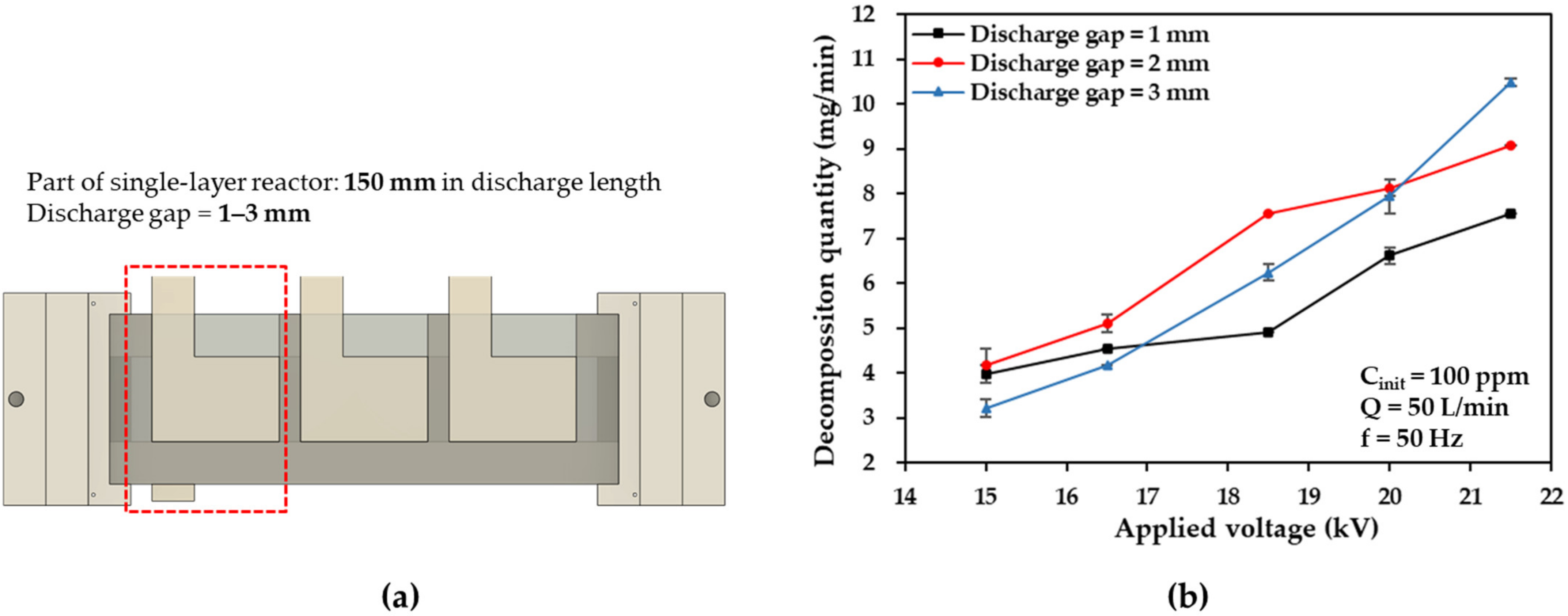
3.1. Optimization of the Discharge Gap between High-Voltage and Ground Electrodes

The discharge gap is considered to be one of the most crucial parameters in DBD reactor configurations that affects the initial discharge voltage and power density, thereby determining the decomposition characteristics of the DBD reactors for exhaust gases [3,22,28]. To determine the optimum discharge gap distance for large-flow DBD reactors, part of the single-layer DBD reactor discharge length (equal to 150 mm) was adopted to investigate the effects of discharge gap thickness (for values in the range of 1–3 mm), as shown in Figure 3a. The toluene to be decomposed was diluted with air to a concentration of 100 parts per million (ppm), adjusted by the MFC to a flow rate of 50 L/min, and humidified through a water bath. In this study, the temporary reactor was energized by high voltages at 50 Hz (f) in the range of 15–21.5 kV (zero-to-peak value).
As a function of the applied voltage, Figure 3b shows how the discharge gap affects the toluene decomposition quantity. When the applied voltages were 15–18.5 kV, the highest toluene decomposition quantity was observed at the discharge gap of 2 mm between electrodes. This result indicates that as the thickness of the discharge gap across the electrodes decreases, the stability of the generated plasma increases at a relatively lower voltage due to the enhanced electric field strength [29]. However, the faster flow velocity of the gas through the plasma zone owing to the thinner discharge gap results in decreased residence times in the plasma zone and lower decomposition quantities. In contrast, when the discharge gap becomes thicker, a higher applied voltage is required to sustain a stable plasma to achieve an equivalent decomposition quantity [30]. Therefore, the discharge gap of 2 mm is optimum for the development of the large-flow DBD reactors in this study in terms of the discharge voltage and residence time in the plasma zone.

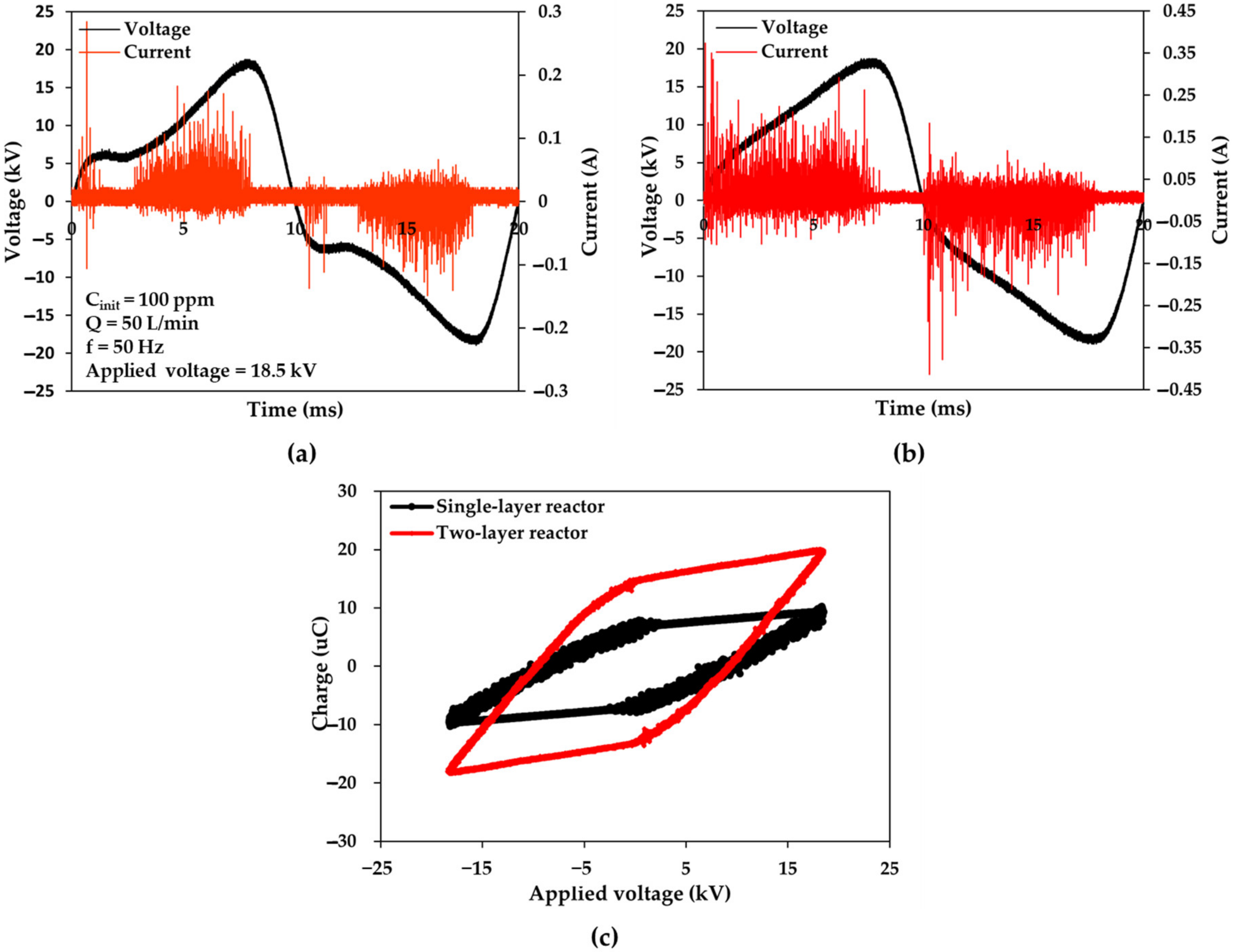
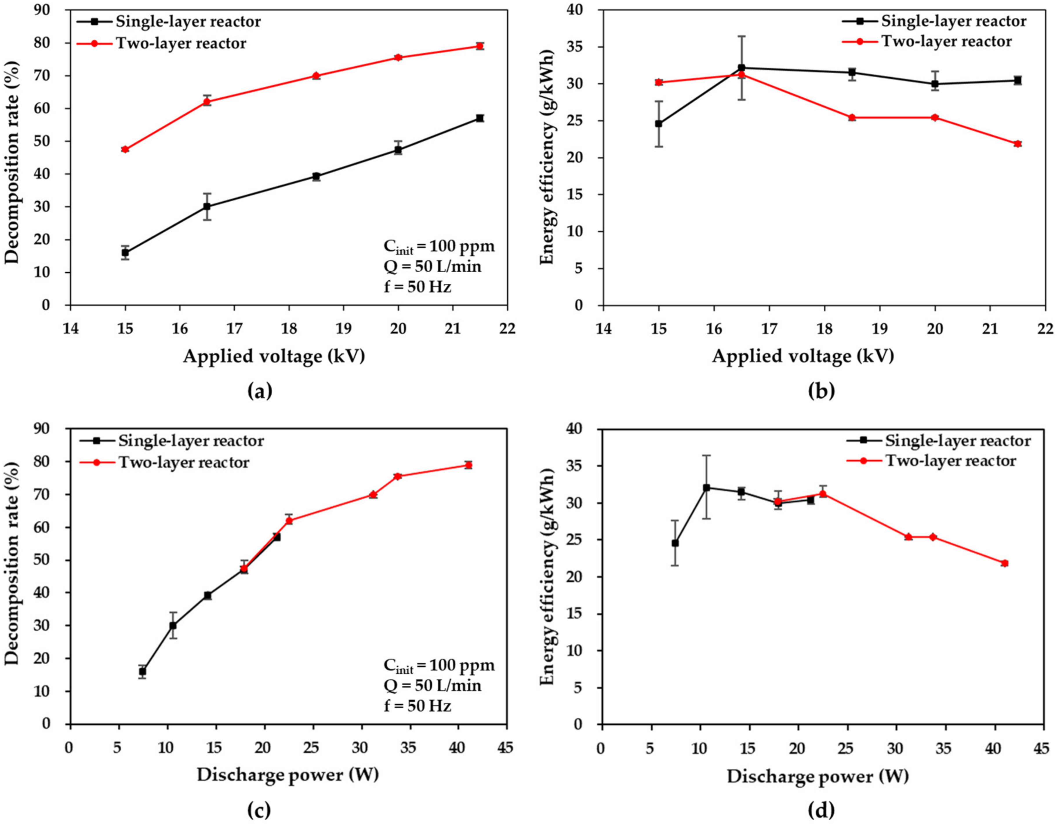
3.2. Effects of Applied Voltage at Large Flow Rates

Figure 4a,b depict the typical voltages and currents for discharges in single-layer and two-layer DBD reactors at 50 Hz and 18.5 kV, respectively, in which the initial toluene concentrations and gas flow rates were maintained at 100 ppm and 50 L/min, respectively. The first halves of each semiperiod are marked by short, intense pulses. A pulse may consist of one or more microdischarges that occur simultaneously whenever a threshold voltage is exceeded across the interelectrode space (>14 kV in the single-layer DBD reactor). Additionally, a higher voltage was observed at the first half of each semiperiod in the two-layer reactor with the same voltage applied; this led to higher discharge power per discharge unit time. This is attributed to the fact that the larger capacitance ratio leads to a higher voltage across the gas gap in the two-layer reactor, as can be observed in the Lissajous figures in Figure 4c [22]. Furthermore, the two-layer reactor system consumes much higher discharge powers at the given applied voltages (31.20 W at 18.5 kV) compared with the 14.14 W consumed by the single-layer reactor, due to its large discharge space (twice as large) and the higher voltage across the gas gap. This finding suggests that greater power can be transported to the plasma to dissociate molecules in toluene-mixed air by using a multilayer structure with alternating layers of electrodes (based on the single-layer reactor design).
The plots of the toluene decomposition rate and energy efficiency versus voltage and discharge power are depicted in Figure 5 for single- and two-layer DBD reactors, where the initial toluene concentration of 100 ppm and gas flow rate of 50 L/min of the toluene-mixed air (intended to be treated) are maintained. As shown in Figure 5a, at increased applied voltages, the decomposition rates in the two DBD reactors increase considerably. As the applied voltage increases from 15 kV to 21.5 kV, the decomposition rate increases from 16% to 57% at 21.5 kV in the single-layer reactor and from 47.5% to 79% in the two-layer reactor. It has also been reported that increased applied voltages contribute to larger numbers of energetic electrons, which is conducive to the production of reactive species and the probability of collisions with toluene molecules [8]. The increased applied voltage has a positive effect on the toluene decomposition rate. The trend of these results is similar to that of the applied voltage in large-flow DBD reactors at a flow rate of 50 L/min, compared with other low-flow reactors, as reported by Guo et al. [4,31] (at 0.1 L/min) and Jiang et al. [4,31] (at 1.08 L/min). Moreover, a remarkable difference in the toluene decomposition rate between the two reactors was observed at all applied voltages possibly because the two-layer reactor (0.24 s) was associated with a mean residence time (for individual toluene molecules in the plasma, zone) which was twice as large as that of the single-layer reactor (0.12 s) at 50 L/min. This result suggests the superiority of the multilayer structure of the two-layer reactor regarding the decomposition rate at the same process capacity (50 L/min).
As shown in Figure 5c, the same decomposition rates were observed at the same discharge power in the single- and two-layer reactors, thus exhibiting the same decomposition characteristics per unit discharge power. This implies that the multilayer structure of the two-layer reactor is feasible in terms of the discharge power.
Conversely, the energy efficiency increased initially and then decreased slightly as the applied voltage increased in the single-layer reactor case; the two-layer reactor presented a similar trend, but the response was better than that of the single-layer reactor at the applied voltage of 15 kV and comparable at 16.5 kV. Subsequently, the response decreased considerably, as shown in Figure 5b. The energy efficiency changes from 24.57 g/kWh to 32.14 g/kWh, drops to 30.44 g/kWh at 21.5 kV in the single-layer reactor case, and slightly increases from 30.20 g/kWh to 31.27 g/kWh before decreasing to 21.85 g/kWh in the two-layer reactor case. This finding may be attributed to the fact that a partial discharge occurred at a lower applied voltage range; this produced an insufficient quantity of high-energy electrons and active species that contributed to the decomposition of toluene, and thus resulted in higher energy efficiency [25,26]. However, the partial discharge gradually changes into a full plasma discharge with an increase in the applied voltage, thus resulting in the generation of an excessive number of high-energy electrons and active species. This causes a decrease in energy efficiency; this phenomenon was more prominent in the two-layer reactor due to the considerably higher decomposition rates. These findings indicate that the two-layer reactor can process faster flow rates. In addition, when decomposition occurs at the same discharge power, the single- and two-layer reactors yield similar energy efficiency outcomes, as shown in Figure 5d. These results demonstrate the feasibility of the two-layer reactor and its superiority in energy efficiency due to the higher decomposition rate compared to the single-layer reactor.

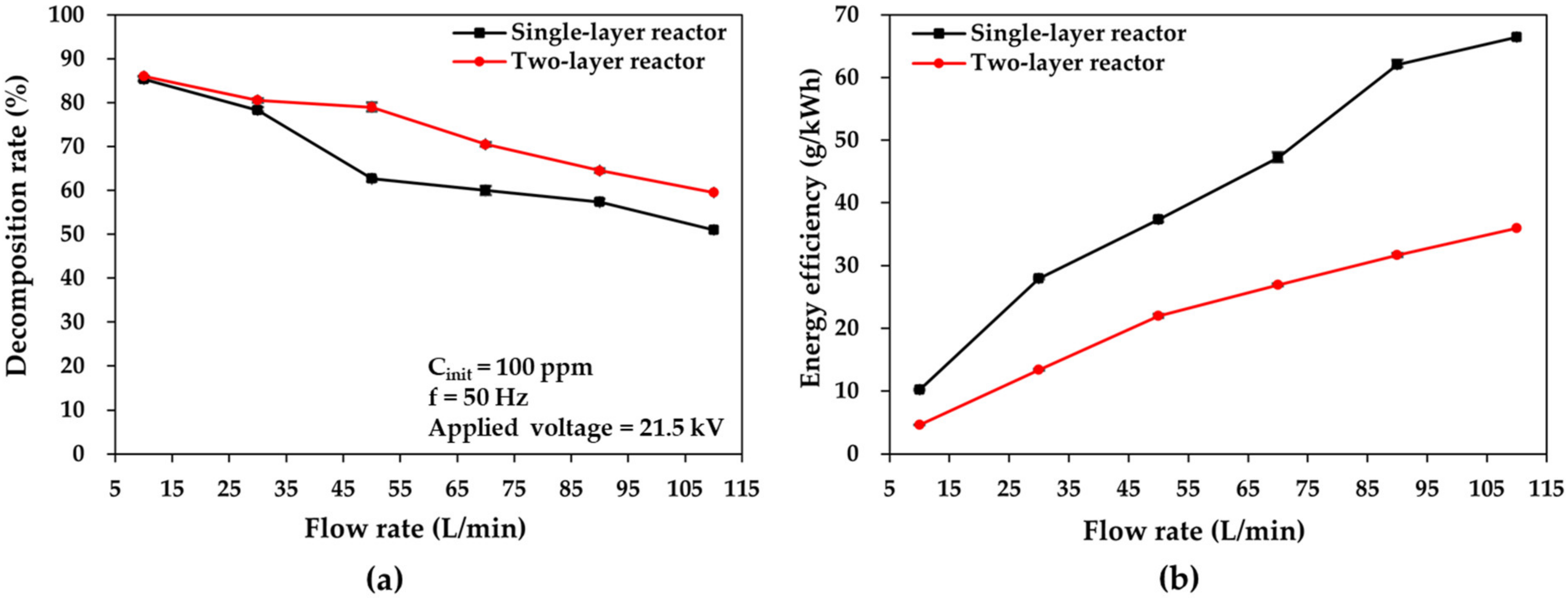
3.3. Effects of Flow Rate on Large-Flow DBD Reactors

Toluene’s discharge characteristics and decomposition performance are also affected by the gas flow rate. Figure 6 shows graphs of the toluene decomposition rate and energy efficiency versus the gas flow rate for single- and two-layer reactors at the applied voltage of 21.5 kV. The results in Figure 6 show that the toluene decomposition rate decreased with increased gas flow rates at the set applied voltage. In contrast, both reactors resulted in increases in their corresponding energy efficiency. The same phenomenon was also observed by Jiang et al. [32], who used small-flow DBD reactors (0.5–2 L/min). When the gas flow rate rises from 10 to 110 L/min, the toluene decomposition rates decrease from 85% to 51% at 110 L/min in the single-layer reactor case and from 86% to 59.5% in the two-layer reactor case. In the lower range of flow rates (10 to 30 L/min), the single-layer reactor achieved decomposition rates comparable to those of the two-layer reactor, even though the two-layer reactor resulted in a residence time that was twice as long as that of the single-layer reactor. This can be attributed to the adequate residence time of the toluene molecules in the discharge zone of both reactors in the lower flow rate range, ensuring a high probability of collisions for the toluene molecules, energetic electrons, and active species; thus, the decomposition rates of the two reactors were close to each other [26,27]. There was, however, a significant difference between the decomposition rates between the two reactors when the flow rates increased from 50 to 110 L/min. This is attributed to the residence time differences, as these offset the adverse effects observed at increased flow rates in the two-layer reactor. This implies that the two-layer reactor in the multilayer structure exhibits superior decomposition characteristics in terms of the decomposition rate at higher flow rates, indicating a larger processing capacity.
At the same time, the energy efficiency increased from 10.20 g/kWh to 66.43 g/kWh at 110 L/min in the single-layer reactor and from 4.63 g/kWh to 35.99 g/kWh in the two-layer reactor case. It has been reported that increased flow rates lead to an increased number of toluene molecules (per unit discharge time) dissociated in the plasma zone (which contains an abundance of active species), thereby improving the energy efficiency considerably [33]. In addition, the single-layer reactor yielded higher energy efficiencies at all flow rates, which may be attributed to the fact that the energetic electrons and active species resulting from the discharge power deposited in the single-layer reactor can be fully utilized for toluene dissociation, thus leading to higher energy efficiency, whereas the discharge power deposited in the two-layer reactor is too large to be fully utilized.
In conclusion, the two-layer reactor is superior to the single-layer reactor in terms of the decomposition rate at all flow rates; however, in terms of energy efficiency, the single-layer is more advantageous. This implies that the two-layer reactor may be overqualified for use in the flow-rate range of 10–110 L/min and could be adapted to handle much higher flow rates to achieve comparable or larger energy efficiencies than those of the single-layer reactor.

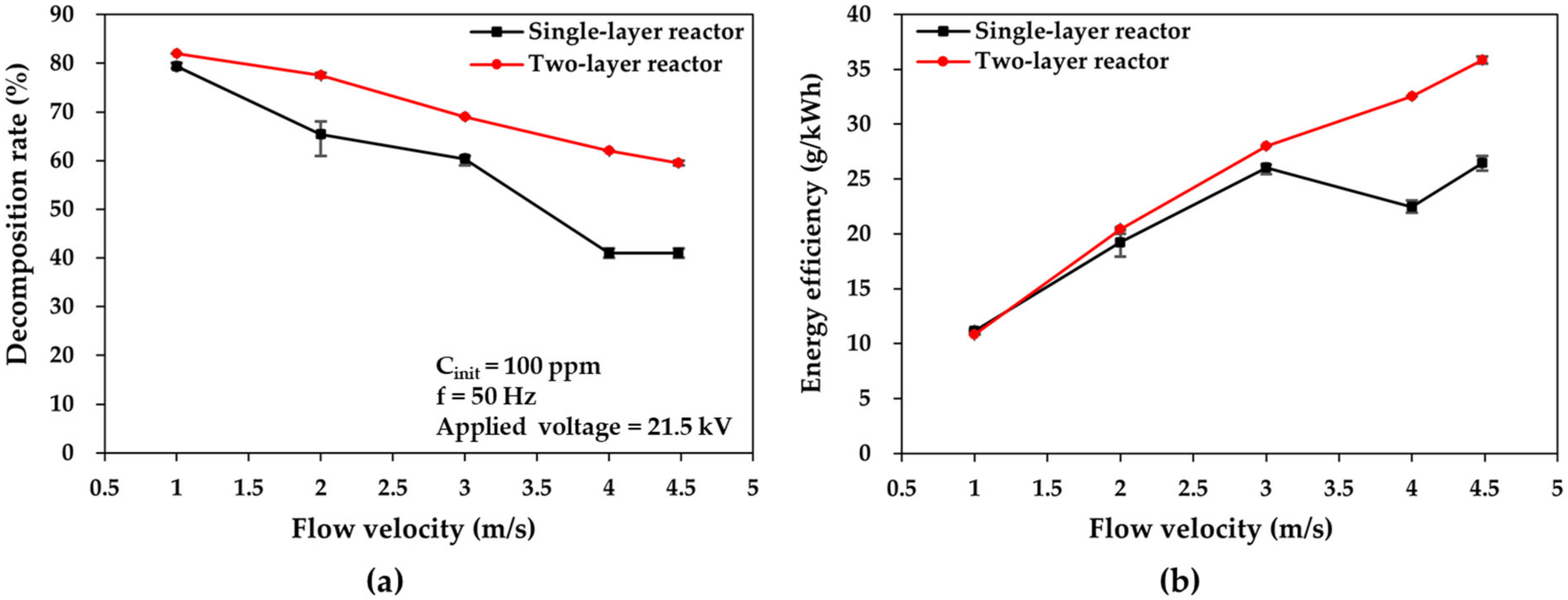
3.4. Effects of Flow Velocity on Large-Flow DBD Reactors

The two types of DBD reactors were compared at different flow velocities, i.e., different residence times. Furthermore, the flow velocities in the reactors were 1, 2, 3, 4, and 4.583 m/s, which corresponded to residence times of 0.5, 0.25, 0.167, 0.125, and 0.109 s, respectively. Figure 7 displays the plots of the toluene decomposition rate and energy efficiency versus flow velocity in the cases of the two reactors, when the applied voltage and toluene concentration were fixed at 21.5 kV and 100 ppm, respectively. In Figure 7a, as the flow velocity increased from 1 to 4.583 m/s, the toluene decomposition rate decreased from 79% to 41% at 4.583 m/s, i.e., at a flow rate of 55 L/min in the single-layer reactor, and from 82% to 59.5% at 4.583 m/s, i.e., at a flow rate of 110 L/min in the two-layer reactor.
The enlarged flow velocity, i.e., the reduced residence time, adversely affects the toluene decomposition rate. The results in the large-flow DBD reactors (for flow rates of up to 110 L/min) concur with the results at smaller flow rates in other DBD reactors, as observed by Chen et al. [34,35] at 1 L/min and by Zhu et al. [34,35] at 0.36–1 L/min. Furthermore, the decomposition rate in the single-layer reactor exhibited a more abrupt decrease at a fixed applied voltage than that in the two-layer reactor case; this can be attributed to the higher discharge power per discharge unit time in the two-layer reactor, as explained in Section 3.1, which leads to a higher decomposition rate in the upper flow-velocity range.
As shown in Figure 7b, as the flow velocity increased from 1 to 4.583 m/s, the energy efficiency increased from 11.16 to 26.43 g/kWh in the single-layer reactor case and from 10.80 to 35.85 g/kWh in the two-layer reactor case. The energy efficiency in both reactors increased at increased flow velocities; this can be attributed to the increased number of toluene molecules per unit discharge time. It was also found that the difference in energy efficiency between the two reactors increased as the flow velocity increased. This is because the toluene decomposition quantity was lower in the single-layer reactor case due to the more abrupt decrease in the decomposition rate. Therefore, regarding the decomposition rate and the higher level of energy efficiency, the decomposition performance of the two-layer reactor is superior to that of the single-layer reactor in terms of flow velocity. Additionally, the processing capability of the two-layer reactor is double that of one-layer reactor at the same flow velocity.

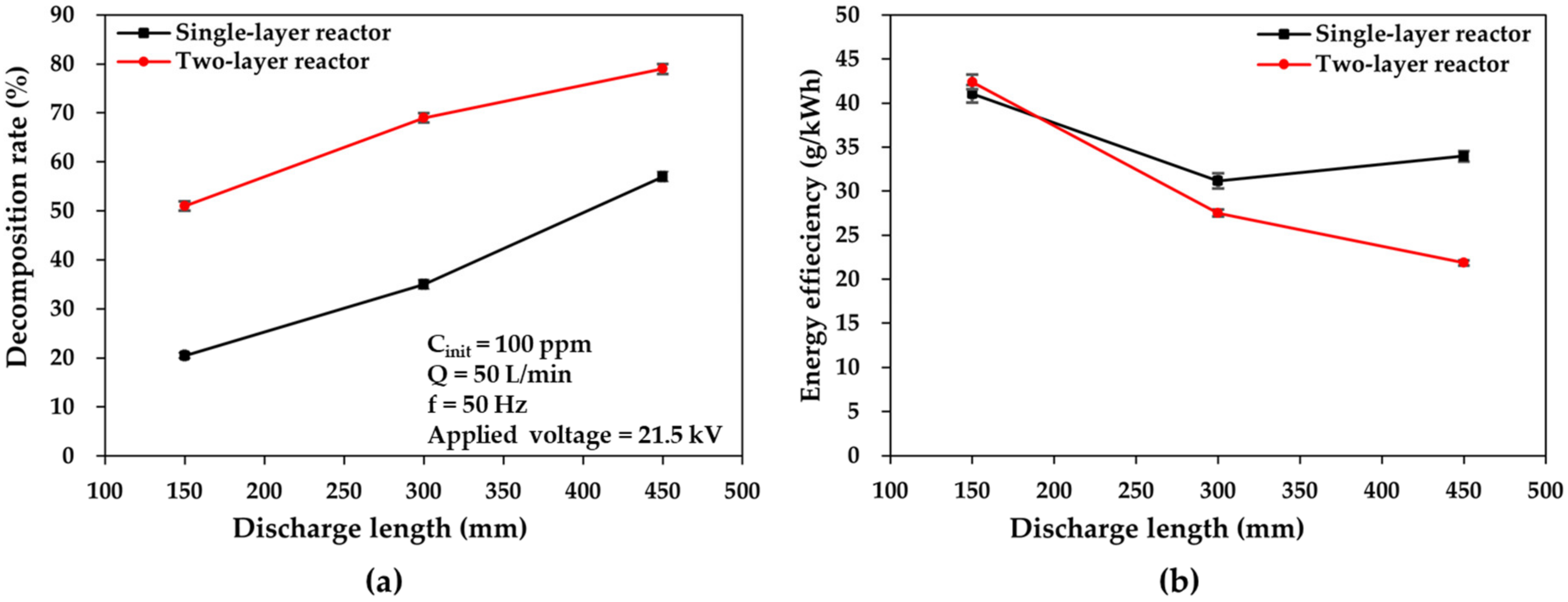
3.5. Effects of Discharge Length on Large-Flow DBD Reactors

Figure 8 shows plots of the toluene decomposition rate and energy efficiency versus discharge length for the two DBD reactors at an applied voltage of 21.5 kV and a flow rate of 50 L/min. The high-voltage electrodes of the two DBD reactors were designed to comprise three parts with discharge lengths of 150, 300, and 450 mm from the gas inlet.
In both reactors, as the discharge length increases, the decomposition rate of toluene increases, as illustrated in Figure 8a. As the discharge length increases from 150 mm to 450 mm, the toluene decomposition rate increases from 21% to 57% and from 57% to 79% in the single- and two-layer reactors, respectively. This is because the extended discharge length creates a larger plasma zone, which can help increase both the average energetic electron density and the number of microdischarges, thus contributing to the toluene decomposition quantity per unit discharge time at the set flow rate of 50 L/min. The occurrence of this phenomenon in large-flow DBD reactors (at the flow rate of 50 L/min) compared with the results at smaller flow rates in other DBD reactors was also reported by Zhang et al. [36,37,38] at 0.5 L/min, Ashford et al. [36,37,38] at 0.0419 L/min, and Chang et al. [36,37,38] at 0.5 L/min.
However, the corresponding energy efficiency in the single-layer reactor decreased from 41.08 to 33.98 g/kWh as the discharge length increased (Figure 8b). It was also reported that the increased discharge length caused an increase in power consumption for the generation of an enlarged plasma zone [36], which led to a higher decomposition quantity per discharge time in the single-layer reactor case; in turn, this finally improved energy efficiency. Conversely, the two-layer reactor exhibited the same trend (from 42.39 to 21.85 g/kWh), but the decrease in energy efficiency was considerably higher. In the two-layer reactor, however, the excessive energy input caused by the increased discharge length caused a more abrupt decrease in energy efficiency compared with the single-layer reactor, given that the larger discharge space can yield a relatively greater decomposition quantity per discharge time at shorter discharge lengths. Nevertheless, it still exhibited comparable energy efficiency for a broad range of discharge lengths. These findings prove the superiority of the multilayer structure of the two-layer reactor in terms of the discharge length and provide directive data for the future configuration design of large-flow DBD reactors.

4. Conclusions

In summary, a scalable large-flow DBD reactor (single-layer reactor) was proposed and fabricated for VOC abatement. Based on the single-layer reactor, another large-flow DBD reactor with a multilayer structure (two-layer reactor) was developed. The effects of applied voltage, gas flow velocity, gas flow rate, and discharge length on decomposition performances, including the decomposition rate and energy efficiency in large-flow DBD reactors, were also investigated. Moreover, by comparing the decomposition performances between the two types of DBD reactors, the feasibility and superiority of multilayer structures in large-flow DBD reactor configurations were demonstrated. The experimental results revealed that the performances of large-flow DBD in toluene decomposition displayed characteristics similar to those of small-flow DBD reactors on the lab scale, as demonstrated in Section 3. For example, increasing the gas flow velocity and rate has a negative effect on the decomposition rate; however, it is favorable for energy efficiency. These findings indicate the feasibility of large-flow plasma generation, which has not been reported in other previous studies.
In addition, in the single-layer reactor, the best decomposition rate of 85% was achieved at a flow rate of 10 L/min, and the corresponding energy efficiency was 10.20 g/kWh. When the flow rate increased to 110 L/min, a decomposition rate of 51% and energy efficiency of 66.43 g/kWh were observed. Conversely, in the two-layer reactor, the best decomposition rate of 86% was also achieved at 10 L/min, with the corresponding energy efficiency of 4.63 g/kWh. Moreover, a decomposition rate of 59.5% and energy efficiency of 35.99 g/kWh were achieved at a faster flow rate of 110 L/min. Therefore, large-flow DBD reactors turned out to be effective and efficient for toluene abatement. Additionally, the higher decomposition performances of the two-layer reactor at faster flow rates confirm that the processing capability can be enhanced by employing a multilayer structure, providing a viable scheme for the configuration of DBD systems for practical use.
Nevertheless, there are still issues that need to be overcome for practical applications in industry. First, despite the effectiveness of large-flow DBD reactors in the decomposition of toluene, the environmental risk of their by-products needs an in-depth investigation and evaluation. Second, only the decomposition performances using toluene were demonstrated in this study. Accordingly, additional investigations are required to understand the chemical reactions involved as well as the decomposition mechanism for multiple VOC mixtures in large-flow DBD systems. Finally, despite the achievement of a toluene decomposition rate of 59.5% at a fast flow rate of 110 L/min, further processing capabilities (e.g., 1000 L/min or faster) are still required. Accordingly, an upscaled, large-flow DBD reactor in a multilayer structure (ten layers), which can cope with gas decomposition up to 1000 L/min for VOC abatement, is being developed.

Author Contributions

Conceptualization, M.X., Y.F., K.N., Z.L., Y.S. and A.O.; methodology, M.X., Y.F., K.N. and Z.L.; validation, M.X., Y.F. and Z.L.; formal analysis, M.X.; investigation, M.X., Y.F. and Z.L.; resources, M.X., Y.F. and Z.L.; data curation, M.X., Y.F. and Z.L.; writing—original draft preparation, M.X.; writing—review and editing, M.X., Y.F., K.N., Z.L., Y.S. and A.O.; visualization, M.X., K.N. and Y.F.; supervision, A.O.; project administration, A.O.; funding acquisition, M.X. and A.O. All authors have read and agreed to the published version of the manuscript.

Funding

This work was supported in part by JST SPRING, grant number JPMJSP2106, and by the Cooperative Research Project of the Research Center for Biomedical Engineering.

Institutional Review Board Statement

Not applicable.

Informed Consent Statement

Not applicable.

Data Availability Statement

Data are contained within the article.

Conflicts of Interest

The authors declare no conflict of interest.

References

  1. Song, M.Y.; Chun, H. Species and characteristics of volatile organic compounds emitted from an auto-repair painting workshop. Sci. Rep. 2021, 11, 16586. [Google Scholar] [CrossRef] [PubMed]
  2. Stockwell, C.E.; Coggon, M.M.; Gkatzelis, G.I.; Ortega, J.; McDonald, B.C.; Peischl, J.; Aikin, K.; Gilman, J.B.; Trainer, M.; Warneke, C. Volatile organic compound emissions from solvent- and water-borne coatings—Compositional differences and tracer compound identifications. Atmos. Chem. Phys. 2021, 21, 6005–6022. [Google Scholar] [CrossRef]
  3. Lu, W.; Abbas, Y.; Mustafa, M.F.; Pan, C.; Wang, H. A review on application of dielectric barrier discharge plasma technology on the abatement of volatile organic compounds. Front. Environ. Sci. Eng. 2019, 13, 30. [Google Scholar] [CrossRef]
  4. Guo, Y.; Ye, D.; Chen, K.; He, J. Toluene removal by a DBD-type plasma combined with metal oxides catalysts supported by nickel foam. Catal. Today 2007, 126, 328–337. [Google Scholar] [CrossRef]
  5. Abdelaziz, A.A.; Ishijima, T.; Seto, T. Humidity effects on surface dielectric barrier discharge for gaseous naphthalene decomposition. Phys. Plasmas 2018, 25, 043512. [Google Scholar] [CrossRef]
  6. Liang, P.; Jiang, W.; Zhang, L.; Wu, J.; Zhang, J.; Yang, D. Experimental studies of removing typical VOCs by dielectric barrier discharge reactor of different sizes. Process. Saf. Environ. Prot. 2015, 94, 380–384. [Google Scholar] [CrossRef]
  7. Blin-Simiand, N.; Jorand, F.; Magne, L.; Pasquiers, S.; Postel, C.; Vacher, J.-R. Plasma reactivity and plasma-surface interactions during treatment of toluene by a dielectric barrier discharge. Plasma Chem. Plasma Process. 2008, 28, 429–466. [Google Scholar] [CrossRef]
  8. Saleem, F.; Rehman, A.; Ahmad, F.; Khoja, A.H.; Javed, F.; Zhang, K.; Harvey, A. Removal of toluene as a toxic VOC from methane gas using a non-thermal plasma dielectric barrier discharge reactor. RSC Adv. 2021, 11, 27583–27588. [Google Scholar] [CrossRef]
  9. Iwai, T.; Inoue, H.; Kakegawa, K.; Ohrui, Y.; Nagoya, T.; Nagashima, H.; Miyahara, H.; Chiba, K.; Seto, Y.; Okino, A. Development of a high-efficiency decomposition technology for volatile chemical warfare agent Sarin using dielectric barrier discharge. Plasma Chem. Plasma Process. 2020, 40, 907–920. [Google Scholar] [CrossRef]
  10. Suenaga, Y.; Takamatsu, T.; Aizawa, T.; Moriya, S.; Matsumura, Y.; Iwasawa, A.; Okino, A. Plasma gas temperature control performance of metal 3D-printed multi-gas temperature-controllable plasma Jet. Appl. Sci. 2021, 11, 11686. [Google Scholar]
  11. Suenaga, Y.; Kawano, H.; Takamatsu, T.; Matsumura, Y.; Ito, N.; Iwasawa, A.; Okino, A. Ultrasonic-combined plasma bubbling for adherent bacteria disinfection on medical equipment. Plasma Chem. Plasma Process. 2022, 42, 575–586. [Google Scholar] [CrossRef]
  12. Aida, M.; Iwai, T.; Okamoto, Y.; Miyahara, H.; Seto, Y.; Okino, A. Development of an ionization method using hydrogenated plasma for mass analysis of surface adhesive compounds. J. Anal. At. Spectrom. 2018, 33, 578–584. [Google Scholar] [CrossRef]
  13. Černáková, L.; Kováčik, D.; Zahoranová, A.; Černák, M.; Mazúr, M. Surface modification of polypropylene non-woven fabrics by atmospheric-pressure plasma activation followed by acrylic acid grafting. Plasma Chem. Plasma Process. 2005, 25, 427–437. [Google Scholar] [CrossRef]
  14. Suenaga, Y.; Takamatsu, T.; Aizawa, T.; Moriya, S.; Matsumura, Y.; Iwasawa, A.; Okino, A. Influence of Controlling Plasma Gas Species and Temperature on Reactive Species and Bactericidal Effect of the Plasma. Appl. Sci. 2021, 11, 11674. [Google Scholar] [CrossRef]
  15. Kurosawa, M.; Takamatsu, T.; Kawano, H.; Hayashi, Y.; Miyahara, H.; Ota, S.; Okino, A.; Yoshida, M. Endoscopic Hemostasis in porcine gastrointestinal tract using CO2 low-temperature plasma jet. J. Surg. Res. 2019, 234, 334–342. [Google Scholar] [CrossRef] [Green Version]
  16. Nomura, Y.; Takamatsu, T.; Kawano, H.; Miyahara, H.; Okino, A.; Yoshida, M.; Azuma, T. Investigation of blood coagulation effect of nonthermal multigas plasma jet in vitro and in vivo. J. Surg. Res. 2017, 219, 302–309. [Google Scholar] [CrossRef] [PubMed]
  17. Chen, S.-Y.; Kuo, Y.-L.; Wang, Y.-M.; Hsu, W.-M.; Chien, T.-H.; Lin, C.-F.; Kuo, C.-H.; Okino, A.; Chiang, T.-C. Atmospheric pressure tornado plasma jet of polydopamine coating on graphite felt for improving electrochemical performance in vanadium redox flow batteries. Catalysts 2021, 11, 627. [Google Scholar] [CrossRef]
  18. Yanagawa, Y.; Kawano, H.; Kobayashi, T.; Miyahara, H.; Okino, A.; Mitsuhara, I. Direct protein introduction into plant cells using a multi-gas plasma jet. PLoS ONE 2017, 12, e0171942. [Google Scholar] [CrossRef] [Green Version]
  19. Kawano, H.; Takamatsu, T.; Matsumura, Y.; Miyahara, H.; Iwasawa, A.; Okino, A. Influence of gas temperature in atmospheric non-equilibrium plasma on bactericidal effect. Biocontrol. Sci. 2018, 23, 167–175. [Google Scholar] [CrossRef] [PubMed] [Green Version]
  20. Miyake, T.; Shimada, M.; Matsumoto, Y.; Okino, A. DNA damage response after ionizing radiation exposure in skin keratinocytes derived from human-induced pluripotent stem cells. Int. J. Radiat. Oncol. Biol. Phys. 2019, 105, 193–205. [Google Scholar] [CrossRef]
  21. Montero-Montoya, R.; López-Vargas, R.; Arellano-Aguilar, O. Volatile organic compounds in air: Sources, distribution, exposure and associated illnesses in children. Ann. Glob. Health. 2018, 84, 225–238. [Google Scholar] [CrossRef] [Green Version]
  22. Wang, J.; Cheng, S.; Liu, N.; Lu, N.; Shang, K.; Jiang, N.; Li, J.; Wu, Y. Degradation of toluene by tube-tube coaxial dielectric barrier discharge: Power characteristics and power factor optimization. Environ. Technol. 2021, 44, 897–910. [Google Scholar] [CrossRef]
  23. Kogelschatz, U. Dielectric-barrier discharges: Their history, discharge physics, and industrial applications. Plasma Chem. Plasma Process. 2003, 23, 1–46. [Google Scholar] [CrossRef]
  24. Pemen, A.J.M.; Chirumamilla, V.R.; Beckers, F.J.C.M.; Hoeben, W.F.L.M.; Huiskamp, T. An SDBD plasma-catalytic system for on-demand air purification. IEEE Trans. Plasma Sci. 2018, 46, 4078–4090. [Google Scholar] [CrossRef] [Green Version]
  25. Schiavon, M.; Torretta, V.; Casazza, A.; Ragazzi, M. Non-thermal plasma as an innovative option for the abatement of volatile organic compounds: A review. Water Air Soil Pollut. 2017, 228, 388. [Google Scholar] [CrossRef]
  26. Mei, D.; Zhu, X.; He, Y.; Yan, J.D.; Tu, X. Plasma-assisted conversion of CO2 in a dielectric barrier discharge reactor: Understanding the effect of packing materials. Plasma Sources Sci. Technol. 2015, 24, 015011. [Google Scholar] [CrossRef] [Green Version]
  27. Tu, X.; Gallon, H.J.; Twigg, M.V.; Gorry, P.A.; Whitehead, J.C. Dry reforming of methane over a Ni/Al 2 O 3 catalyst in a coaxial dielectric barrier discharge reactor. J. Phys. D Appl. Phys. 2011, 44, 274007. [Google Scholar] [CrossRef] [Green Version]
  28. Mahammadunnisa, S.; Reddy, E.L.; Reddy, P.R.M.K.; Subrahmanyam, C. A facile approach for direct decomposition of nitrous oxide assisted by non-thermal plasma. Plasma Processes Polym. 2013, 10, 444–450. [Google Scholar] [CrossRef]
  29. Sultana, S.; Vandenbroucke, A.M.; Leys, C.; De Geyter, N.; Morent, R. Abatement of VOCs with alternate adsorption and plasma-assisted regeneration: A review. Catalysts 2015, 5, 718–746. [Google Scholar] [CrossRef]
  30. Mei, D.; Tu, X. Conversion of CO2 in a cylindrical dielectric barrier discharge reactor: Effects of plasma processing parameters and reactor design. J. CO2 Util. 2017, 19, 68–78. [Google Scholar] [CrossRef]
  31. Jiang, L.; Nie, G.; Zhu, R.; Wang, J.; Chen, J.; Mao, Y.; Cheng, Z.; Anderson, W.A. Efficient degradation of chlorobenzene in a non-thermal plasma catalytic reactor supported on CeO2/HZSM-5 catalysts. J. Environ. Sci. 2017, 55, 266–273. [Google Scholar] [CrossRef] [PubMed]
  32. Jiang, N.; Zhao, Y.; Shang, K.; Lu, N.; Li, J.; Wu, Y. Degradation of toluene by pulse-modulated multistage DBD plasma: Key parameters optimization through response surface methodology (RSM) and degradation pathway analysis. J. Hazard. Mater. 2020, 393, 122365. [Google Scholar] [CrossRef]
  33. Tang, S.; Yuan, D.; Rao, Y.; Li, N.; Qi, J.; Cheng, T.; Sun, Z.; Gu, J.; Huang, H. Persulfate activation in gas phase surface discharge plasma for synergetic removal of antibiotic in water. Chem. Eng. J. 2018, 337, 446–454. [Google Scholar] [CrossRef]
  34. Chen, J.; Xie, Z.; Tang, J.; Zhou, J.; Lu, X.; Zhao, H. Oxidation of toluene by dielectric barrier discharge with photo-catalytic electrode. Chem. Eng. J. 2016, 284, 166–173. [Google Scholar] [CrossRef]
  35. Zhu, R.; Mao, Y.; Jiang, L.; Chen, J. Performance of chlorobenzene removal in a nonthermal plasma catalysis reactor and evaluation of its byproducts. Chem. Eng. J. 2015, 279, 463–471. [Google Scholar] [CrossRef]
  36. Zhang, H.; Li, K.; Sun, T.; Jia, J.; Lou, Z.; Feng, L. Removal of styrene using dielectric barrier discharge plasmas combined with sol–gel prepared TiO2 coated γ-Al2O3. Chem. Eng. J. 2014, 241, 92–102. [Google Scholar] [CrossRef]
  37. Ashford, B.; Tu, X. Non-thermal plasma technology for the conversion of CO2. Curr. Opin. Green Sustain. Chem. 2017, 3, 45–49. [Google Scholar] [CrossRef] [Green Version]
  38. Chang, C.-L.; Bai, H.; Lu, S.-J. Destruction of styrene in an air stream by packed dielectric barrier discharge reactors. Plasma Chem. Plasma Process. 2005, 25, 641–657. [Google Scholar] [CrossRef]
Figure 1. Schematics of large-flow dielectric barrier discharge (DBD) reactors in top, cross-sectional, and bottom views: (a) scalable single-layer and (b) multilayer (two-layer) DBD reactors.
Plasma 06 00016 g001
Figure 2. Schematic of the experimental setup using the single-layer DBD reactor (AC: alternating current; MFC: mass-flow controller; VOC: volatile organic compound).
Plasma 06 00016 g002
Figure 3. (a) Single-layer DBD reactor with a discharge length of 150 mm, and (b) effects of discharge gap on toluene decomposition quantity plotted as a function of the applied voltage.
Plasma 06 00016 g003
Figure 4. Waveforms of (a) typical voltages and currents of discharges in the single-layer DBD reactor, (b) two-layer reactor, and (c) corresponding Lissajous figures.
Plasma 06 00016 g004
Figure 5. Effects of applied voltage on (a,c) toluene decomposition rate and (b,d) energy efficiency plotted as a function of applied voltage in the cases of the single- and two-layer DBD reactors at 50 L/min.
Plasma 06 00016 g005
Figure 6. Comparisons of (a) toluene decomposition rate and (b) energy efficiency plotted as a function of flow rate in the cases of single- and two-layer DBD reactors.
Plasma 06 00016 g006
Figure 7. Comparisons of (a) toluene decomposition rate and (b) energy efficiency plotted as a function of flow velocity in the two DBD reactor cases.
Plasma 06 00016 g007
Figure 8. Comparisons of (a) toluene decomposition rate and (b) energy efficiency plotted as a function of discharge length in the two DBD reactor cases.
Plasma 06 00016 g008
Disclaimer/Publisher’s Note: The statements, opinions and data contained in all publications are solely those of the individual author(s) and contributor(s) and not of MDPI and/or the editor(s). MDPI and/or the editor(s) disclaim responsibility for any injury to people or property resulting from any ideas, methods, instructions or products referred to in the content.

