Article

Drying Behaviour of Al2O3 Inks Containing Carboxymethylcellulose (CMC) for Use in Colloidal Processing

by
Bruno Medeiros da Silva
1,
Ésoly Madeleine Bento dos Santos
1,
Vinícius Zancanelli Bôsco de Souza
1,
Manuel Fellipe Rodrigues Pais Alves
2,
Carlos Maurício Vieira
3 and
Claudinei dos Santos
1,2,*
1
Escola de Engenharia Industrial Metalúrgica de Volta Redonda EEIMVR, Universidade Federal Fluminense UFF, Av. dos Trabalhadores, 420, Vila Santa Cecília, Volta Redonda 27255-125, RJ, Brazil
2
Faculdade de Tecnologia de Resende FAT, Universidade do Estado do Rio de Janeiro UERJ, Rodovia Presidente Dutra, Km 298, Resende 27537-000, RJ, Brazil
3
Laboratório de Materiais Avançados LAMAV, Universidade Estadual do Norte Fluminense Darcy Ribeiro UENF, Av. Alberto Lamego, 2000–Parque Califórnia, Campos dos Goytacazes 28013-602, RJ, Brazil
*
Author to whom correspondence should be addressed.
Ceramics 2023, 6(2), 935-947; https://doi.org/10.3390/ceramics6020055
Submission received: 2 January 2023 / Revised: 17 March 2023 / Accepted: 24 March 2023 / Published: 6 April 2023
(This article belongs to the Special Issue Advances in Ceramics)

Abstract

:
One of the most important steps in the extrusion processing of ceramic inks is the initial drying of the ceramic parts. This study aimed to investigate the drying behaviour of an Al2O3-based ceramic ink optimised to be processed by extrusion processing methods, e.g., direct ink writing. Carboxymethylcellulose (CMC) was singly added to a suspension of deionised water and Al2O3 (50:50 wt.%) to perform as a dispersing and plasticising agent. To assess moisture loss as a function of time, the ceramic inks were extruded into two types of polymeric moulds: one with a completely closed profile producing cylindrical samples (disks) and one with an open profile producing ceramic bars. After the injection of the inks, the moulds were exposed to different controlled temperatures (20 and 40 °C) for up to 180 h; moisture loss and warpage were periodically measured, and exponential mathematical expressions (moisture loss × drying time) were obtained. The Al2O3-bars dried for 24 h in open moulds at 20 and 40 °C presented longitudinal warpages of 4.5% and 9%, respectively, while the Al2O3 disks dried in closed moulds presented warpages of 3.5% and 7% in these same temperatures (20 and 40 °C, respectively). The samples were sintered at 1610 °C for 4 h and characterised by scanning electron microscopy (SEM), relative density (Archimedes principle), and X-ray diffraction (XRD), presenting a relative density of 92.3 ± 0.5%, α-Al2O3 as crystalline phase and grain with equiaxed morphology varying between 1 and 5 μm.

1. Introduction

Rapid prototyping processes based on the additive manufacturing (AM) layer-by-layer principle are characterised by their potential to process customised parts on near-net shapes [1,2,3]. Robocasting, also known as direct ink writing (DIW), is an AM technique based on the direct extrusion of highly concentrated ceramic slurry (ink) through computer-controlled layer-by-layer deposition used to build 3D structures [4,5,6]. In recent years, this technique has attracted much attention as an efficient route to manufacture 3D porous parts or open structures such as scaffolds [7,8,9], as well as multi-layered materials [10,11]. However, there are three major technical limitations to the use of this technique in certain applications: (i) difficulty in achieving full densification, (ii) poor surface quality, and (iii) low geometric fidelity in relation to the reference model (warpage), which is associated with the huge shrinkage observed during the drying and sintering steps [12].
The colloidal processing route is the usual choice for the development of extrudable ceramic ink’s [13,14,15,16,17,18]. In this type of processing, anionic and cationic surfactants are added in different and successive steps, depending on the surface charge of the material to be processed, in order to control the viscosity of the suspension [12,15,18]. This protocol allows the transition from a fluid state, dispersed suspension, to a pasty behaviour, with adequate plasticity for extrusion processing. However, recent work has explored the use of “gel-embedded suspensions”, e.g., hydrogels, that act as carrier media for the powders [15,19]. In this type of approach, the rheological properties of the ink’s do not derive directly from the surface interactions between the particles but from the rheological properties of the gel to which the powder is added. Routes based on hydrogels have the advantage of being functional for a wide range of materials and require a unique additive, as in hydrogels based on poloxamers (Pluronic F-127) or cellulose (Carboxymethylcellulose-CMC) [20,21,22,23,24,25].
The hydrogel system based on Pluronic F-127 is certainly one of the most explored to date [12,15,20,22]. However, the gelation process of this copolymer is thermo-dependent, being susceptible to expressive variations in viscosity even at room temperature (5–40 °C) [20,22]. On the other hand, CMC-based hydrogels are thermally stable and considered multifunctional, as they also play the role of dispersant, owing to their slightly anionic character [21,23,26,27]. CMC is a polymeric compound of high molecular weight that has been reported to present good adsorption over Al2O3 surfaces, acting as a dispersant and promoting efficient rheological stabilisation [21,27]. In addition, since it is characterised by long cellulose chains, it tends to interact with several particles at the same time, generating a bridging effect, thus ensuring the ink’s plasticity [27].
Drying [28,29] is an important step for all consolidation techniques based on colloidal processing, especially for ceramic parts processed by robocasting or injection moulding. There is a very complex relationship between the forming, drying and sintering processes of ceramic parts in such a way that any variation in this behaviour can significantly affect the production process and the final quality of the printed parts, even being mainly responsible for part failure. However, the drying process complexity has been neglected in AM processing since few studies addressing the drying of ceramic materials have been carried out, especially with advanced ceramics.
During the drying process, heat exchange and mass transport occur. Furthermore, variation in size due to the outflow of water is observed, resulting in an approximation of the particles. The evolution of the drying process is usually evidenced by the drying curves, which are divided into stages. During drying, shrinkage occurs continuously until reaching critical moisture (Mc). Below Mc, shrinkage is insignificant, and mass balance is achieved during this period [30]. Thus, water should be removed slowly and homogeneously to avoid differential shrinkage, which can lead to material internal stress, resulting in the formation and subsequent propagation of cracks [31].
One way to reduce shrinkage in inks used in robocasting or injection moulding processes is to use a high solid content; however, highly loaded inks usually present higher viscosity, demanding greater pressure throughout the extrusion process and leading to problems such as nozzle clogging, thus reducing printability [32]. Knowing the ink behaviour during drying enables the adjustment of the composition to reduce warpage without considerably increasing the solid content.
This study aimed to investigate the drying behaviour of a typical Al2O3-based ceramic ink, with CMC as an additive, optimised for use in extrusion-based processes, such as DIW.

2. Experimental Procedure

2.1. Materials

Commercially available Al2O3 (CT 3000 LS SG; Almatis, Leetsdale, PA, USA) and CMC powders (Mw = 250,000; density = 1.6 g/cm3; Lamberti Iberia S.A.U., Castellón, Spain) were used to develop the ceramic inks. The manufacturer’s information regarding the purity of the Al2O3 powder is shown in Table 1.
The alumina powder was characterised for particle size distribution using a laser-scattering particle size distribution analyser (LA-950; Horiba Ltd., Longjumeau, France), and particle morphology was analysed using a scanning electron microscope (SEM). In addition, the crystallographic composition was analysed via X-ray diffraction (XRD).

2.2. Processing

2.2.1. Al2O3 Ink Preparation

The preparation of the inks for robocasting was carried out by dispersing the Al2O3 powder in CMC aqueous solution, resulting in a gel with pseudoplastic behaviour. According to the supplier, the aqueous solution containing 2 wt.% CMC presents viscosity in the range of η = 1–3 Pa s, which is usually a satisfactory base for inks applied in robocasting. However, the inks prepared in this study at this CMC concentration were unsuitable for extrusion, and the formed parts did not maintain their shape. To achieve the correct rheological behaviour, the CMC concentration was raised stepwise (0.5 wt.%) until smooth filaments with no superficial cracks and good shape retention were achieved. Figure 1 shows the obtained inks and extruded parts.
Initially, the deagglomerated Al2O3 powder was weighed on a precision scale (series M, MW; WebLabor, Brazil). In parallel, a solution of 5 wt.% CMC and deionised water was prepared using a magnetic stirring bar until homogenisation (~30 min). During stirring, the suspension was kept at 40 ± 1 °C to facilitate the solubilisation of the polymer in water. As a result of this procedure, a thick gel with 3.1 vol.% CMC was obtained. After that, an ink was formulated by gradually adding Al2O3 powder to the gel aiming to prevent powder agglomeration. The proportion of the final mix was 50 wt.% gel and 50 wt.% Al2O3 powder.

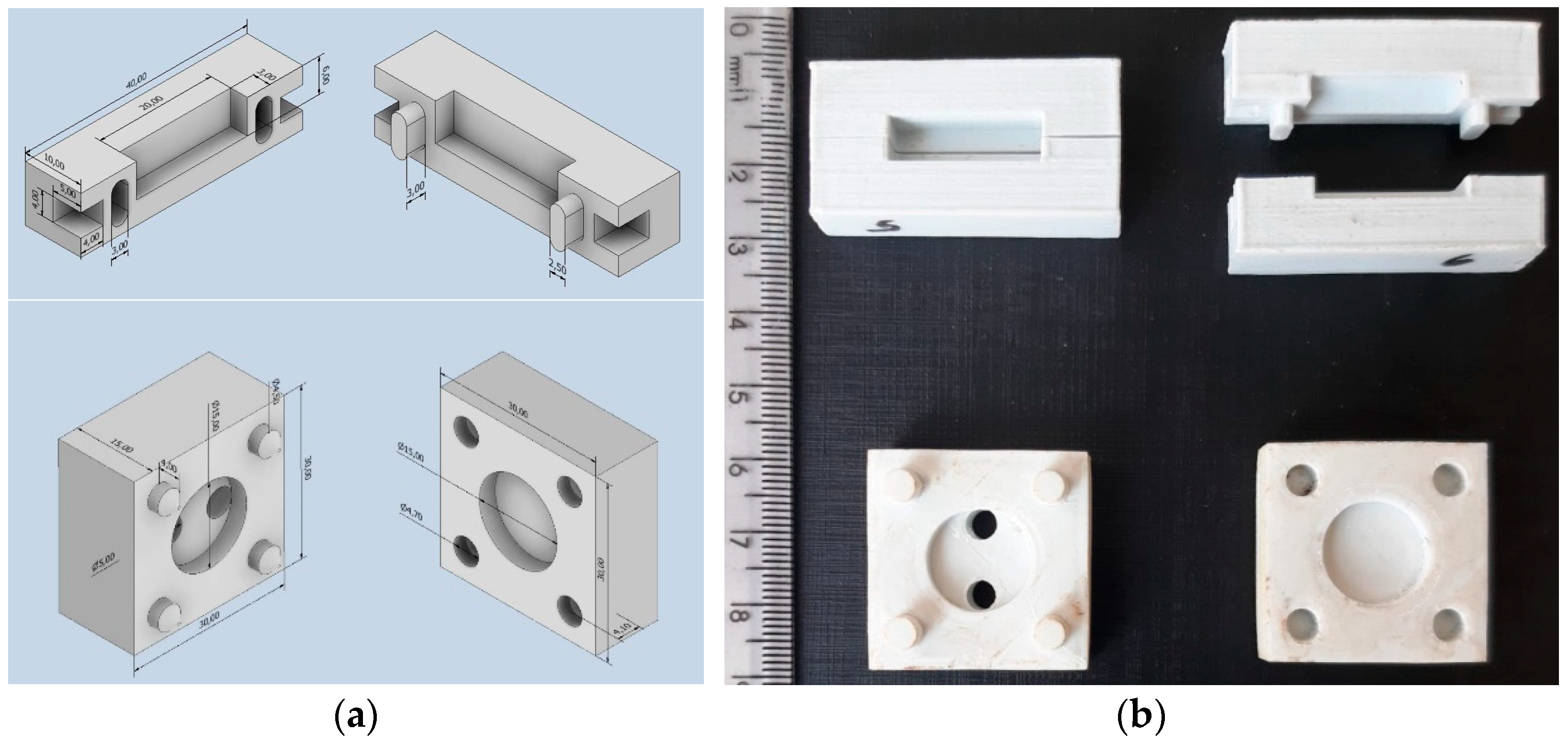
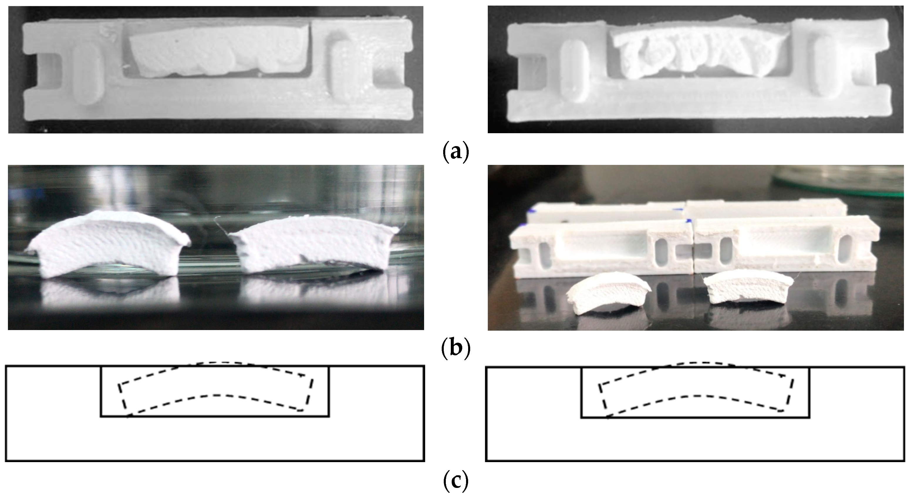
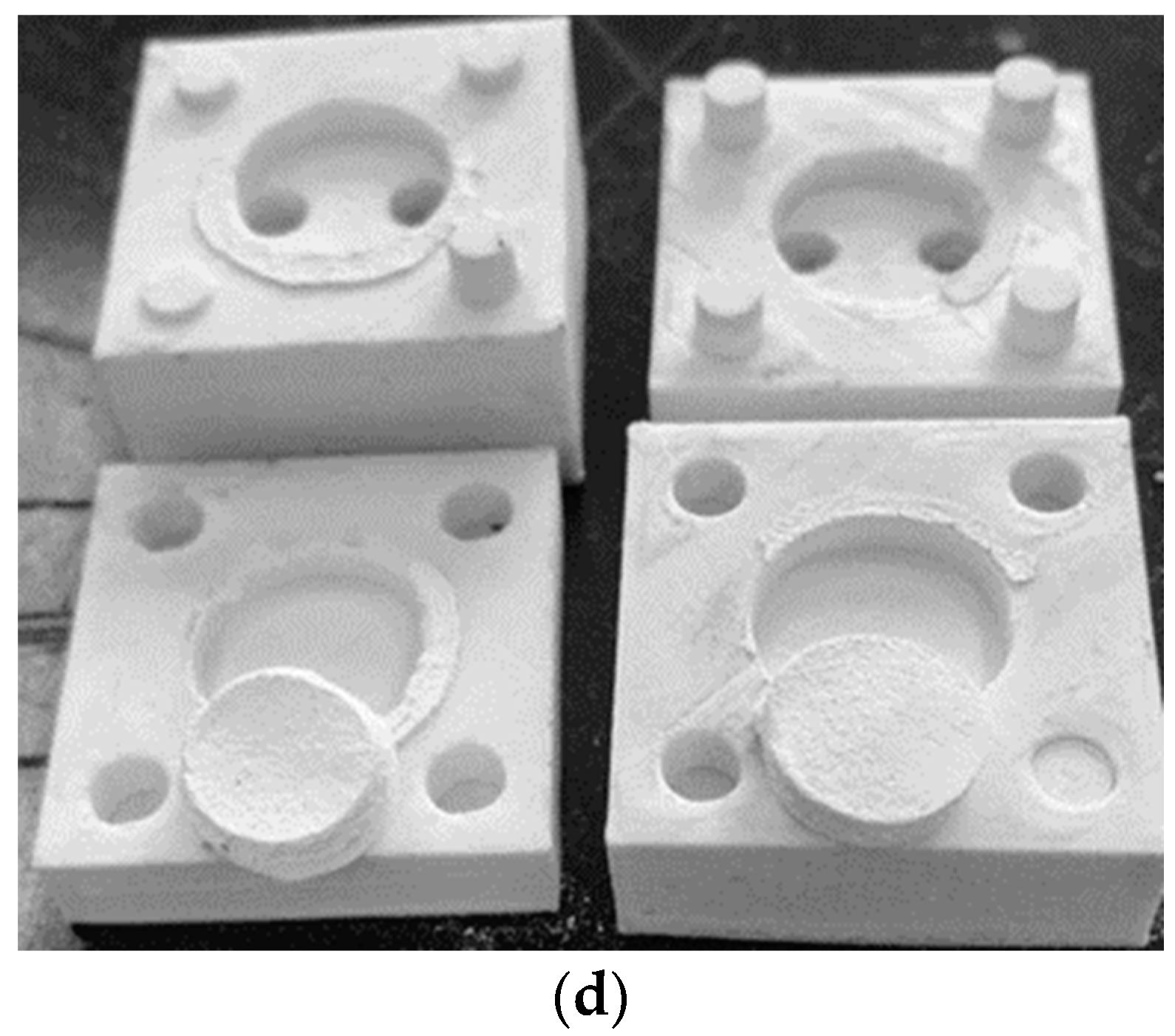
2.2.2. Moulding of the Al2O3 Samples

Two models of moulds were used in this study, one open and the other closed, aiming to simulate extreme heat exchange situations during the drying process to which the extruded moulds are subjected. It was decided to create different geometries of alumina samples depending on the mould used: (1) Open moulds allowed for obtaining ceramic bars. The two-part geometry of the mould facilitated the observation of warping during the drying time. (2) Cylindrical samples (disks) with a surface area different from the bars were obtained from closed moulds.
The moulds employed in the drying tests were produced on an FDM 3D printer (Ender 5 Pro; Creality, Shenzhen, China) with an ABS filament. Figure 2 shows designs and photos of the moulds printed by FDM. A commercial medical syringe (Ø 1.5 mm) was used to simulate the use of robocasting equipment. To this end, the ink was deposited in the syringe and extruded into the moulds until complete filling.

2.2.3. Drying and Dilatometry

All moulds used in the drying tests were initially weighed on a precision scale of −0.001 g (series M, MW; WebLabor, Mogi das Cruzes, Brazil) and the weight of the experimental devices was registered. The optimised ceramic inks were injected into each mould, and the sets (mould plus ink) were weighed—this point was considered time 0. The sets of open and closed moulds were placed in a drying furnace and kept at controlled temperatures of 20 and 40 °C for up to 7.5 days. At minimum intervals of 15 min, all sets of moulds were weighed and then replaced in their respective furnace. Thus, after 7.5 days, curves of mass loss (moisture) as a function of drying time were constructed.
The warpage profile of the green samples processed in an open mould was determined as a function of the drying time from the warpage rate (WR) [33,34], as evidenced on Figure 3, which was defined by:
W R = H m a x L × 100 %
where Hmax is the maximum height of the warpage and L is the length of the green body after drying. At different times, images of the samples were obtained using a digital camera, and the digitised images were compared using Image J software [35]. Thus, the Hmax values were determined and applied to Equation (1).
The obtained dry samples, rectangular bars, were measured using a calliper (Absolute Digimatic; Mitutoyo Sulamericana, Suzano, Brazil). Since all dried samples had maximum dimensions of 6 × 6 × 20 mm, representative samples were subjected to dilatometric analysis (DIL 402; Netsch, Selb, Germany) in an argon atmosphere, adopting the sintering cycle shown in Table 2. Shrinkage was measured on a linear variable differential transducer (LVDT) with a sensitivity of 0.01 mm. Tests were performed in duplicate. After the dilatometry tests, the samples were re-sintered at 1610 °C for 4 h in a conventional oven (MAITEC F1650, São Carlos, Brazil) to complement the densification, using a heating rate of 10 °C/min.
The density of the sintered samples was characterised according to the Archimedes principle [36]. The relative density values of the samples were determined by adopting 3.98 g/cm3 as the theoretical density for α-alumina [37].
For microstructural evaluation, the sintered samples were ground and polished with SiC sandpaper and diamond suspensions (3 and 1 µm). The conditioned samples were then thermally etched at 1575 °C for 15 min at a heating rate of 25 °C/min. To avoid undesirable poor conduction of the electron beam, a thin layer of gold was deposited on the sample surfaces using a K550X metalliser (Quorum Technologies, Lewes, UK) using a 30 mA current for 2 min. The microstructure of the sintered samples was analysed in an SEM/FEG microscope (JSM-7100FT; JEOL, Peabody, MA, USA).
The crystallographic composition of the sintered samples was identified using an X-ray diffractometer (X’Pert PRO; Malvern Panalytical, São Paulo, Brazil) equipped with a CuKα (λ = 1.54 Å) cathode-ray tube. The diffraction spectra were measured in the 20–80° 2θ range with an angular step width of 0.01° at an acquisition time of 50 s/step. The detected crystalline phases were identified by comparing them with standard crystallographic data obtained from the PDF-4-ICSD database, employing Crystal Match 3.12 software.

3. Results and Discussion

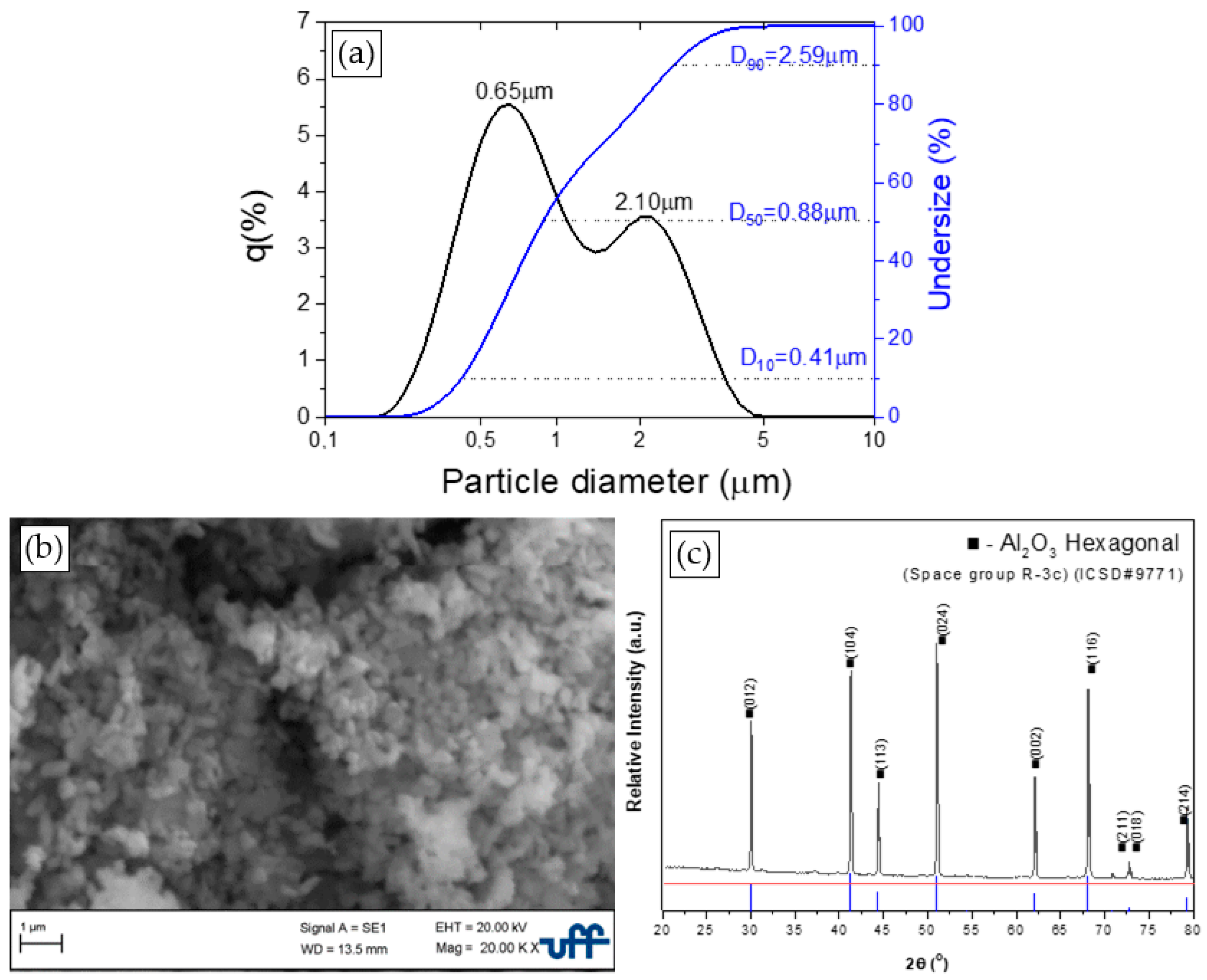
3.1. Powder Characterisation

Figure 4 presents the particle size analysis, XRD, and SEM micrograph representative of the morphology of the Al2O3 particles used in this study.
The results of the particle size distribution analysis, Figure 4a, show a mean size of 1.47 ± 1.1 µm and a bimodal distribution. The two modes are centred at 0.65 and 2.1 µm with a maximum variation of particle sizes between 0.41 and 2.59 μm, respectively. Complementarily, Figure 4b suggests that the morphology of the commercial powder particles resembles semi-spherical shapes with morphological reproducibility. In addition, the X-ray diffractogram, Figure 4c, presents α-Al2O3 (hexagonal) as the only detectable crystalline phase.

3.2. Drying Tests

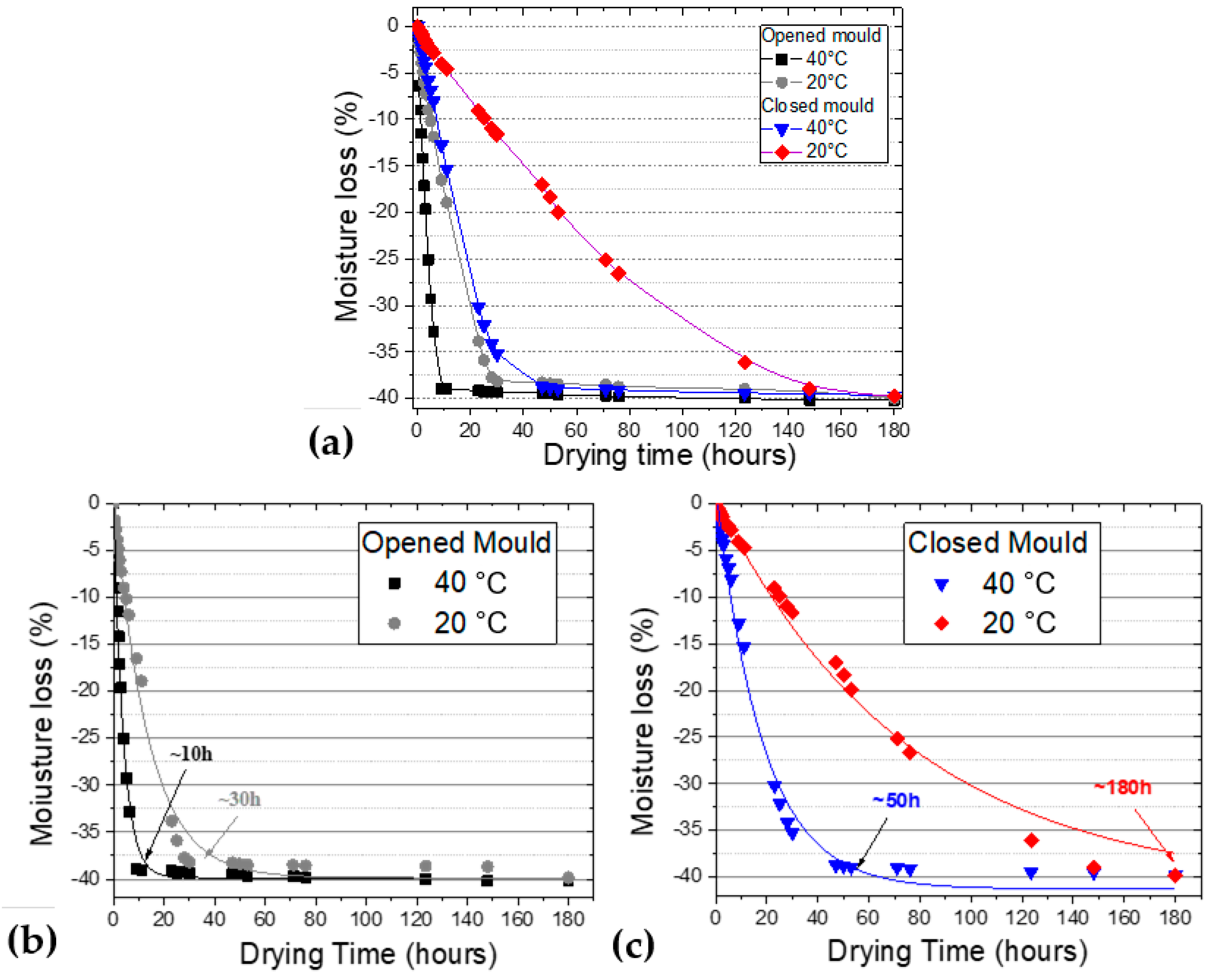
3.2.1. Moisture Loss
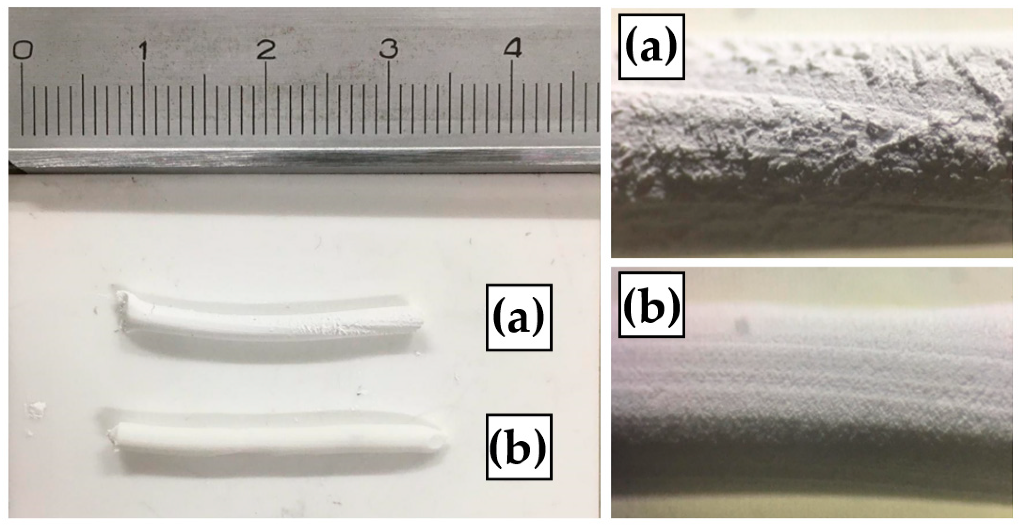
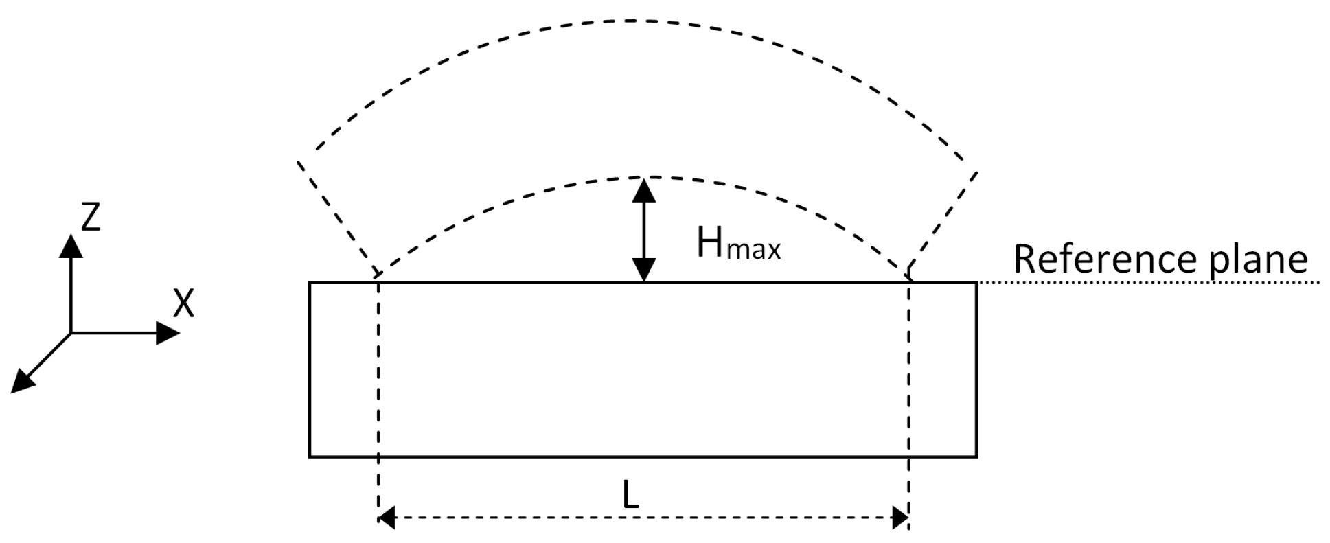
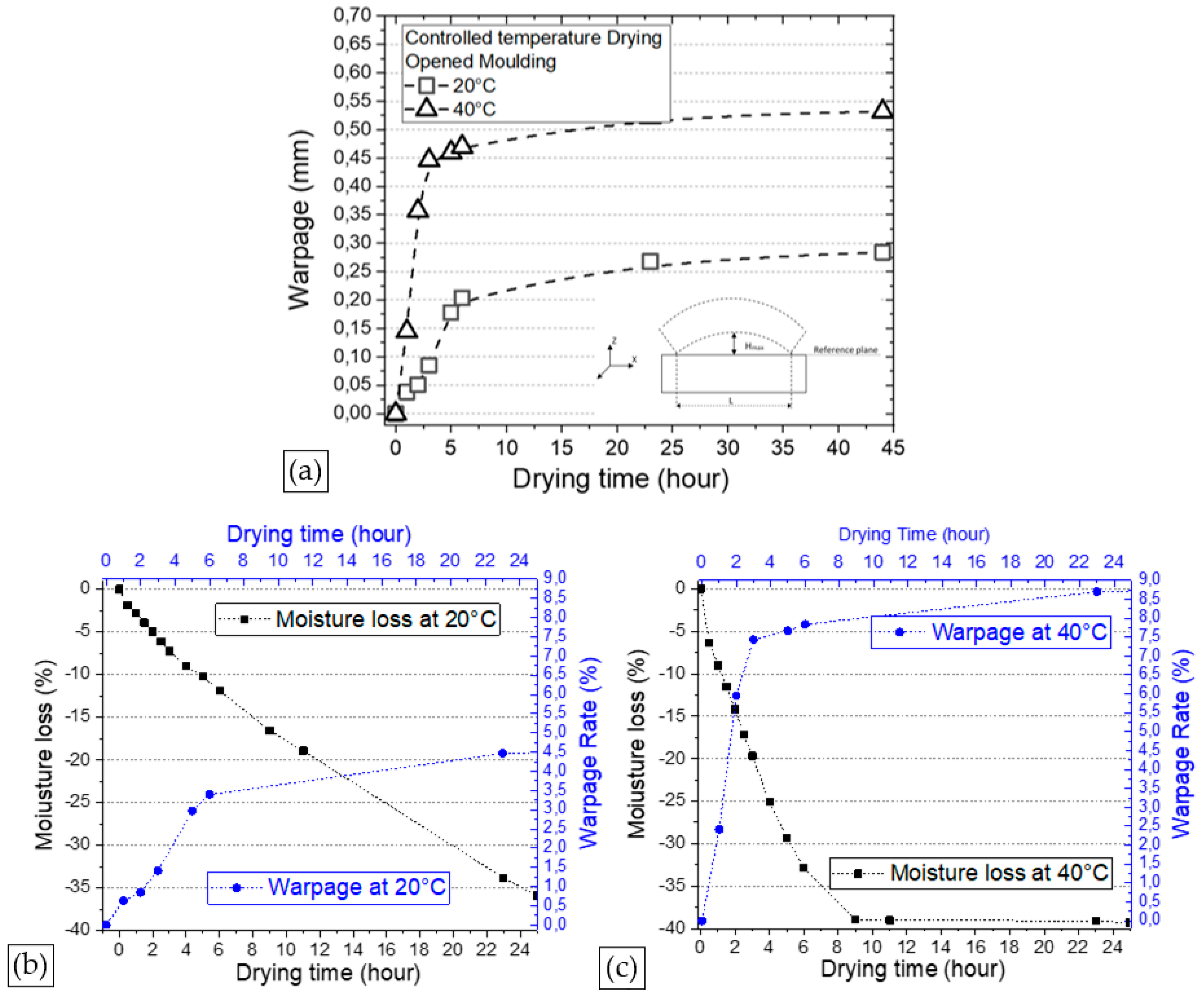
Figure 5 shows the results of the drying tests based on moisture loss as a function of drying temperature. Below, Supplementary Data referring to the weights of the samples before and after the drying period are presented.
Drying occurs through the displacement of moisture from the inside of the material to its surface-moisture evaporation and shrinkage in the material [38]. The rate of these retractions should be controlled during the drying process to avoid the appearance of defects in the final product [39]. The drying curve is a graph that correlates the moisture content of the ceramic material as a function of time.
Figure 5a shows the drying curves of the extruded Al2O3 ink in both the open and closed moulds at temperatures of 20 and 40 °C. The drying curves present two distinct periods for each temperature. In the first stage, the surface is covered by a continuous water film, and moisture evaporation occurs on the surface of the body, with a linear and constant drop in mass loss caused by a high drying rate. This is the most critical period of the drying process, as it is when defects can occur in the parts, such as fractures and cracks arising from shrinkage; therefore, the use of low temperatures is recommended in this stage [40]. In the second stage, the drying rate decreases, and shrinkage ceases; all moisture, i.e., residual water in capillaries and surface water, is completely removed. In this way, evaporation begins inside the solid material, and the vapour reaches the surface by diffusion through the pores [40]. Figure 4c shows the drying curves of the closed moulds. The first period of the curve occurs at 0–50 h and 180 h, respectively, for temperatures of 40 and 20 °C. Samples in the closed moulds presented a lower drying rate when compared with those on the open moulds. Thus, more time was needed for the former to reach the second period of the curve, where shrinkage ceases. This occurred because the magnitude of the first drying stage was dependent on the area of material that was exposed to drying. It is worth noting that this comparative analysis is not conclusive, given that the heat exchange conditions were different between the two types of moulds and the geometry and surface area of the samples in both cases were different.
Mathematical adjustments of the drying curves (moisture loss as a function of time) were performed using the exponential expression represented by Equation (2) for both moulds (open and closed) at different temperatures.
Y = Y 0 + A · e R 0 · X
The results obtained in this work can be represented using Equations (3) and (4) for open moulds and Equations (5) and (6) for closed moulds, thus making it possible for drying times between 0 and 180 h to determine, with a good fit, what will be the moisture loss of a green body for a given drying time.
M 40   ° C = 39.8490 + 40.2798 × e 0.2573 · t   R 2 = 0.9929
M 20   ° C = 39.8490 + 40.6895 × e 0.0733 · t   R 2 = 0.9907
M 40   ° C = 41.2717 + 43.0585 × e 0.0549 · t   R 2 = 0.9914
M 20   ° C = 41.27175 + 41.8416 × e 0.0133 · t   R 2 = 0.9885
where M is moisture loss (%) and t corresponds to a certain drying time (hours).

3.2.2. Warpage

The samples dried in the open moulds, which showed a higher drying rate, were compared as a function of the drying temperature employed. Based on the digitised images presented in Figure 6, a preliminary analysis of the warping degree was performed. Using the procedure described in the ABNT-NBR 14698 standard [41] to verify warping in tempered glasses, the approximate warping degrees for samples dried in closed moulds at different temperatures (20 and 40 °C) were evaluated using scanned images. The results of this warpage analysis as a function of drying time for open moulds are shown in Figure 7.
It is possible to observe that the warpage was more pronounced in the first 10 h of drying, regardless of the drying temperature adopted. The first hours of drying were considered critical to determining the dimensional quality of the green bodies since the shrinkage variation between the surface and the volume of the green bodies was accentuated. As expected, drying performed at temperatures of 40 °C presented total warpage rates two orders of magnitude higher than samples dried at temperatures of 20 °C, which led to significantly higher distortions in the dry samples, as observed in Figure 6b,c.
Because of the difficulties of intermediate warpage measurements on disks obtained from closed moulds, intermediate warpage measurements were not carried out. However, after 24 h of drying (Figure 6d), the warpage measured as a function of the reference geometry was estimated to be around 3.5% and 7% for drying temperatures of 20 and 40 °C, respectively.
Some strategies to control the drying of extrudable inks have been used to avoid significant warping of Al2O3 and ZrO2 pieces produced by additive manufacturing automatically controlled extrusion processing techniques, such as direct ink writing. Between these approaches, the control of humidity in the air and the application of steam during the processing of ceramic pieces were investigated in previous works [10,11]. This strategy effectively reduces the warpage of the green body during processing, as well as in the first hours of drying; however, the temperature control extended for the first 10 h can be a primordial factor for the green body to have the least possible distortions.
The results presented in this investigation are limited to evaluating extreme drying behaviours and their interference in the final warping of an alumina ceramic piece. The choice of the appropriate condition should take into account the dimensional accuracy of the parts and the final surface finishing step usual in parts printed by DIW.
Considering possible industrial applications of Al2O3 ceramic pieces obtained by DIW using Al2O3-H2O-CMC inks, the volume of printed material, the final dimensions of the piece and the need for subsequent stages of surface finishing should not be neglected, but the control of the rate of drying should be prioritised.

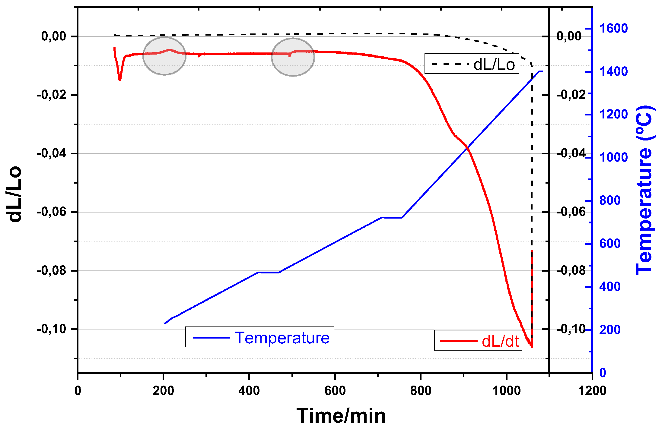
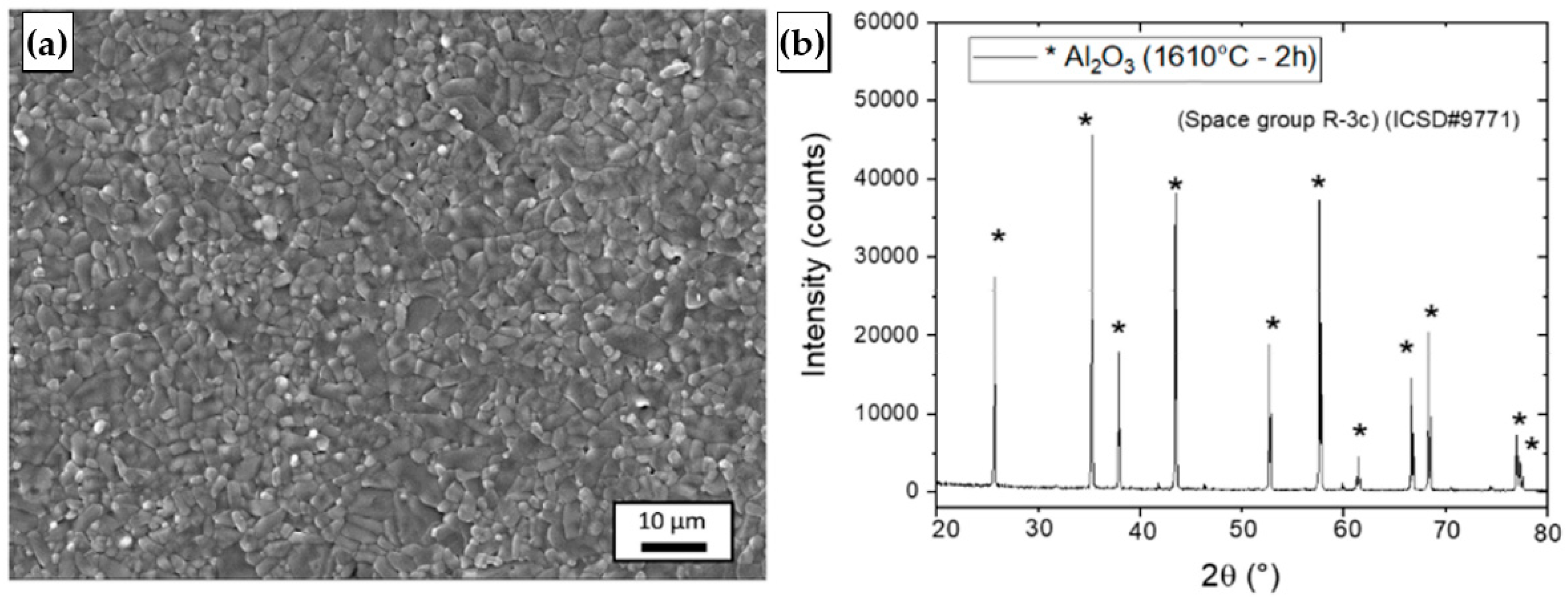
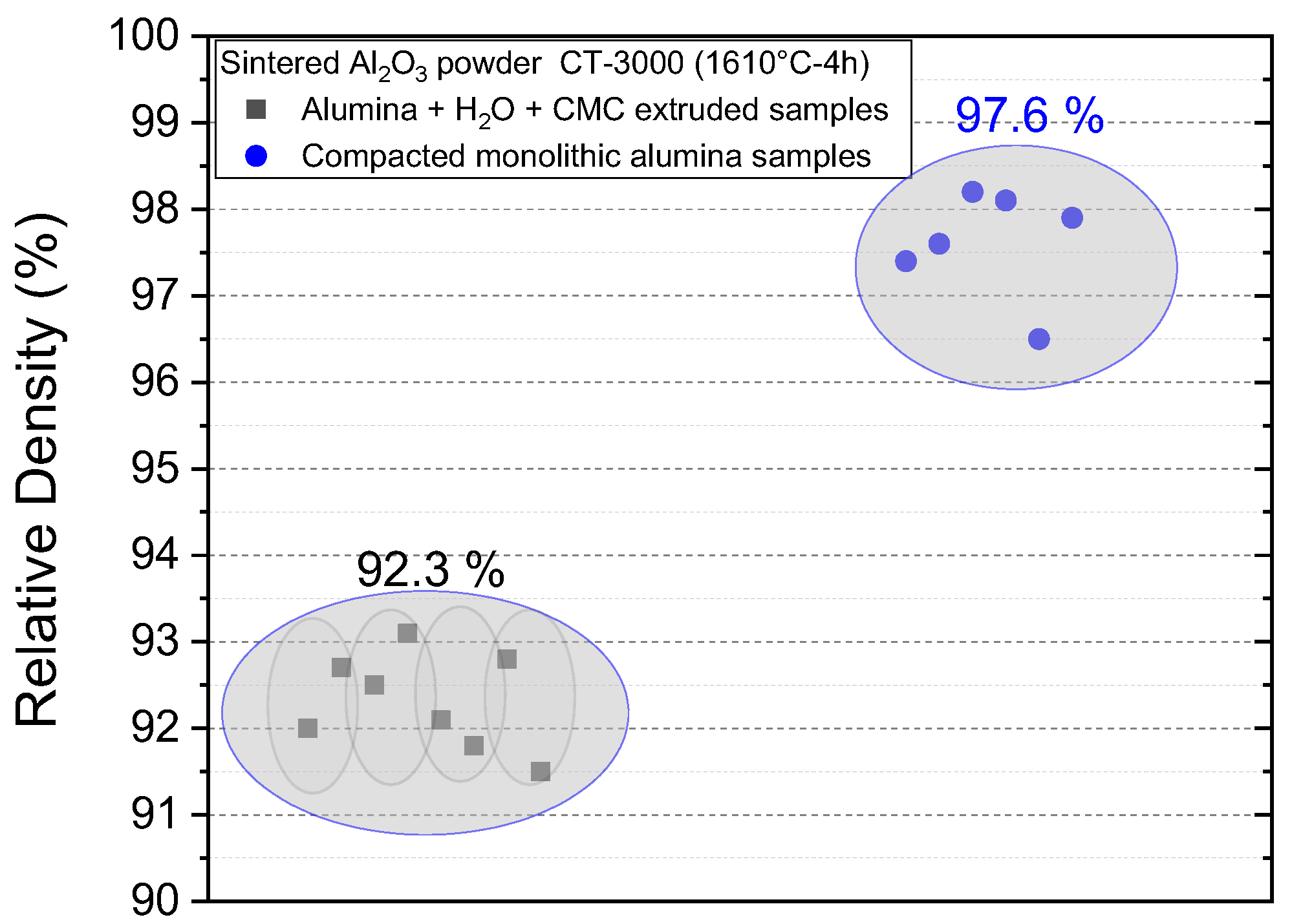
3.3. Sintering Behaviour

Figure 8 shows the characteristic dilatometry curve of the sample obtained with the Al2O3-H2O-CMC inks. The analysis of the shrinkage curves of the moulded samples after the dilatometric tests showed swelling at temperatures close to 200 °C, which could be associated with the accommodation of the powder particles as a result of the output of the residual molecular water atomically present in the particulate system and which was not eliminated under the drying conditions imposed to the samples during the drying test. A change in the shrinkage behaviour could be noticed around 700 °C, which is related to the evaporation of the CMC additive [42]. The most pronounced shrinkage, which is characterised by the action of the densification mechanisms associated with sintering, began at temperatures >870 °C and continued until test interruption at 1100 °C, indicating the occurrence of material densification in this region. As the objective of this study was to evaluate shrinkage during the heating of the ink, the tests were interrupted at 1100 °C. Then, the samples were sintered at 1610 °C for 4 h, when the final densification of the ceramic was reached.
Characterisation results of the sintered samples are shown in Figure 9. A microstructure composed of equiaxed Al2O3 grains with sizes varying between 1 and 5 μm is observed. The XRD pattern suggests α-Al2O3 (hexagonal) as the only crystalline phase present after sintering at 1610 °C for 4 h. These results agree with those reported for alumina ceramics developed by conventional compaction and sintering processes [43].
Regarding relative density, the values observed for the samples submitted to drying in open and closed moulds at 20 and 40 °C did not show statistically significant differences and, in general, were on the order of 92.3 ± 0.5% (1610 °C for 4 h). Figure 10 shows the individual relative density measured for samples obtained via the colloidal processing route using the Al2O3-CMC inks, as well as for a group of samples obtained by the powder technology route, conventional uniaxial compaction (100 MPa), using the same raw material shown in Table 1 and sintered at 1610 °C for 2 h (a heating rate of 10 °C/min). As expected, the compacted products resulting from the samples presented higher relative density, on the order of 97.6 ± 0.3%, because of the higher degree of packing of the particles existing in the green compacted product in relation to that of the ceramic ink developed in this study, which had a solid content of 50 wt% and thus hindered the elimination of the pores existing in the green body compared with the compacted products. However, the values obtained in this study are on the same order of magnitude as those reported in previous studies for extrudable ceramic inks [44] and, depending on the final application intended for the sintered alumina, they may be adequate and viable.

4. Conclusions

Exponential mathematical expressions modelling drying behaviour for extrudable alumina inks composed of Al2O3 (particle size of 1.47 ± 1.1 µm) + H2O + CMC were obtained using 20 °C and 40 °C as room temperatures using different geometry Al2O3 samples (bars and disks).
The use of opened moulds to dry the alumina samples enabled moisture elimination after 30 h (20 °C) and 10 h (40 °C). On the other hand, despite the longer drying time observed in the samples dried at 20 °C, the accumulated warping after 24 h of drying was 4.5%, while the samples dried at 40 °C showed 9% of warping after the same period, representing a greater loss of dimensional quality. The use of closed moulds (alumina disks) systematically increased the time required for the complete drying of the samples, presenting moisture elimination after 180 or 50 h, respectively, with slight gains in dimensional quality, with warpage of around 3.5% and 7%, for samples dried at 20 °C and 40 °C respectively.
The sintering results indicated that the relative density values of alumina did not present statistically significant differences for the drying temperature or the external environment in which the extruded samples were conditioned. Given the increasing use of AM techniques, the creation of specific drying curves for different ceramic systems is an interesting tool to predict indices of shrinkage, warping and densification, thus optimising the construction of ceramic parts with a high degree of complexity.

Supplementary Materials

The following supporting information can be downloaded at: https://www.mdpi.com/article/10.3390/ceramics6020055/s1, Table S1. Weight of the moulds and inks at the initial and final parameters of the drying tests.

Author Contributions

Conceptualization: B.M.d.S., É.M.B.d.S., V.Z.B.d.S., C.M.V. and C.d.S.; Methodology: B.M.d.S., É.M.B.d.S., V.Z.B.d.S. and M.F.R.P.A.; Software: B.M.d.S., V.Z.B.d.S. and M.F.R.P.A.; Formal analysis: É.M.B.d.S., M.F.R.P.A., C.M.V. and C.d.S.; Investigation: B.M.d.S., V.Z.B.d.S. and M.F.R.P.A.; Data curation: M.F.R.P.A.; Writing—Original Draft: B.M.d.S., É.M.B.d.S., V.Z.B.d.S. and C.M.V.; Writing: Review & editing: É.M.B.d.S., M.F.R.P.A., C.M.V. and C.d.S.; Supervision: É.M.B.d.S., C.M.V. and C.d.S.; Project administration: C.d.S.; Funding acquisition: C.d.S. All authors have read and agreed to the published version of the manuscript.

Funding

C. Santos is grateful to the Brazilian agencies FAPERJ (Grant no. E26-202.997/2017) and CNPq (Grant no. 311.119/2017-4) for the financial support received.

Acknowledgments

The authors thank Luciano Pessanha Moreira for their help in the mathematical analyses.

Conflicts of Interest

The authors declared no potential conflict of interest.

References

  1. Lakhdar, Y.; Tuck, C.; Binner, J.; Terry, A.; Goodridge, R. Additive Manufacturing of Advanced Ceramic Materials. Prog. Mater. Sci. 2020, 116, 100736. [Google Scholar] [CrossRef]
  2. Babu, S.S.; Love, L.; Dehoff, R.R.; Peter, W.; Watkins, T.R.; Pannala, S. Additive Manufacturing of Materials: Opportunities and Challenges. MRS Bull. 2015, 40, 1154–1161. [Google Scholar] [CrossRef] [Green Version]
  3. ASTM: F 2792-10; Standard Terminology for Additive Manufacturing Technologies. ASTM International: West Conshohocken, PA, USA, 2010.
  4. Monfared, M.H.; Nemati, A.; Loghman, F.; Ghasemian, M.; Farzin, A.; Beheshtizadeh, N.; Azami, M. A deep insight into the preparation of ceramic bone scaffolds utilizing robocasting technique. Ceram. Int. 2022, 48, 5939–5954. [Google Scholar] [CrossRef]
  5. Shahzad, A.; Lazoglu, I. Direct ink writing (DIW) of structural and functional ceramics: Recent achievements and future challenges. Compos. Part B Eng. 2021, 225, 109249. [Google Scholar] [CrossRef]
  6. Fu, Z.; Freihart, M.; Wahl, L.; Fey, T.; Greil, P.; Travitzky, N. Micro- and macroscopic design of alumina ceramics by robocasting. J. Eur. Ceram. Soc. 2017, 37, 3115–3124. [Google Scholar] [CrossRef]
  7. Miranda, P.; Saiz, E.; Gryn, K.; Antoni, P.T. Sintering and Robocasting of B-Tricalcium Phosphate Scaffolds for Orthopaedic Applications. Acta Biomater. 2006, 2, 457–466. [Google Scholar] [CrossRef] [PubMed]
  8. Lin, K.; Sheikh, R.; Romanazzo, S.; Roohani, I. 3D Printing of Bioceramic Scaffolds-Barriers to the Clinical Translation: From Promise to Reality, and Future Perspectives. Materials 2019, 12, 2660. [Google Scholar] [CrossRef] [PubMed] [Green Version]
  9. Ben-Arfa, B.A.E.; Neto, A.S.; Palamá, I.E.; Salvado, I.M.M.; Pullar, R.C.; Ferreira, J.M. Robocasting of Ceramic Glass Scaffolds: Sol–Gel Glass, New Horizons. J. Eur. Ceram. Soc. 2019, 39, 1625–1634. [Google Scholar] [CrossRef]
  10. Baltazar, J.; Torres, P.M.C.; Olveira, J.D.; Cruz, J.P.; Gouveia, S.; Olhero, S. Influence of Filament Patterning in Structural Properties of Dense Alumina Ceramics Printed by Robocasting. J. Manuf. Process. 2021, 68, 569–582. [Google Scholar] [CrossRef]
  11. Baltazar, J.; Alves, M.F.R.P.; Martins, M.A.; Torres, P.M.C.; Santos, C.; Olhero, S. Flexural Strength of 3Y-TZP Bioceramics Obtained by Direct Write Assembly as Function of Residual Connected-Porosity. J. Mech. Behav. Biomed. Mater. 2022, 126, 105035. [Google Scholar] [CrossRef]
  12. Daguano, J.K.M.B.; Santos, C.; Souza, M.T.T.; Alves, M.F.R.P.; Fernandes, M.H.F.V.; Silva, J.V.L. State of the Art in the use of bioceramics to elaborate 3D Structures using Robocasting. Int. J. Adv. Med. Biotechnol. 2019, 2, 55–70. [Google Scholar] [CrossRef]
  13. Sun, S.; Xia, Q.; Feng, D.; Ru, H. Adsorption effects of polyethylene imine on the rheological properties for robocasting. J. Mater. Sci. 2022, 57, 3057–3066. [Google Scholar] [CrossRef]
  14. Gadea, C.; Spelta, T.; Simonsen, S.B.; Esposito, V.; Bowen, J.R.; Haugen, A.B. Hybrid inks for 3D printing of tall BaTiO3-based ceramics. Open Ceram. 2021, 6, 100110. [Google Scholar] [CrossRef]
  15. Peng, E.; Zhang, D.; Ding, J. Ceramic robocasting: Recent achievements, potential, and future developments. Adv. Mater. 2018, 30, 1802404. [Google Scholar] [CrossRef] [PubMed]
  16. Ben-Arfa, B.A.; Neto, A.S.; Salvado, I.M.M.; Pullar, R.C.; Ferreira, J.M. Robocasting: Prediction of ink printability in sol-gel bioactive glass. J. Am. Ceram. Soc. 2019, 102, 1608–1618. [Google Scholar]
  17. Lorenz, M.; Dietemann, B.; Wahl, L.; Bierwisch, C.; Kraft, T.; Kruggel-Emden, H.; Travitzky, N. Influence of platelet content on the fabrication of colloidal gels for robocasting: Experimental analysis and numerical simulation. J. Eur. Ceram. Soc. 2020, 40, 811–825. [Google Scholar] [CrossRef]
  18. Nan, B.; Olhero, S.; Pinho, R.; Vilarinho, P.M.; Button, T.W.; Ferreira, J.M. Direct ink writing of macroporous lead-free piezoelectric Ba0.85Ca0.15Zr0.1Ti0.9O3. J. Am. Ceram. Soc. 2019, 102, 3191–3203. [Google Scholar] [CrossRef]
  19. del-Mazo-Barbara, L.; Ginebra, M.P. Rheological characterisation of ceramic inks for 3D direct ink writing: A review. J. Eur. Ceram. Soc. 2021, 41, 18–33. [Google Scholar] [CrossRef]
  20. Feilden, E.; Blanca, E.G.T.; Giuliani, F.; Saiz, E.; Vandeperre, L. Robocasting of structural ceramic parts with hydrogel inks. J. Eur. Ceram. Soc. 2016, 36, 2525–2533. [Google Scholar] [CrossRef]
  21. Eqtesadi, S.; Motealleh, A.; Miranda, P.; Pajares, A.; Lemos, A.; Ferreira, J.M. Robocasting of 45S5 bioactive glass scaffolds for bone tissue engineering. J. Eur. Ceram. Soc. 2014, 34, 107–118. [Google Scholar] [CrossRef]
  22. Franco, J.; Hunger, P.; Launey, M.E.; Tomsia, A.P.; Saiz, E. Direct write assembly of calcium phosphate scaffolds using a water-based hydrogel. Acta Biomater. 2010, 6, 218–228. [Google Scholar] [CrossRef] [PubMed] [Green Version]
  23. Eqtesadi, S.; Motealleh, A.; Miranda, P.; Lemos, A.; Rebelo, A.; Ferreira, J.M. A simple recipe for direct writing complex 45S5 Bioglass® 3D scaffolds. Mater. Lett. 2013, 93, 68–71. [Google Scholar] [CrossRef]
  24. Lamnini, S.; Baino, F.; Montalbano, G.; Javed, H.; Smeacetto, F. Printability of carboxymethyl cellulose/glass-containing inks for robocasting deposition in reversible solid oxide cell applications. Mater. Lett. 2022, 318, 132239. [Google Scholar] [CrossRef]
  25. Martínez-Vázquez, F.J.; Pajares, A.; Miranda, P. A simple graphite-based support material for robocasting of ceramic parts. J. Eur. Ceram. Soc. 2018, 38, 2247–2250. [Google Scholar] [CrossRef]
  26. Porsani, N.K.; Santos, M.K.; Rocha, A.M.; Trombini, V.; Ana, P.A.; Tercini, M.B.; Setz, L.F.G. Beta-phosphate tricalcium colloidal processing. Ceram. Int. 2020, 46, 2648–2653. [Google Scholar] [CrossRef]
  27. Zhivkov, A.M.; Hristov, R.P. Adsorption of carboxymethyl cellulose on alumina particles. J. Colloid Interface Sci. 2015, 447, 159–166. [Google Scholar] [CrossRef] [PubMed]
  28. Lauro, N.; Oummadi, S.; Alzina, A.; Nait-Ali, B.; Smith, D.S. Computer model of drying behaviour of ceramic green bodies with particular reference to moisture content dependent properties. J. Eur. Ceram. Soc. 2021, 41, 7321–7329. [Google Scholar] [CrossRef]
  29. Fokin, P.; Peretyagin, P.; Smirnov, A. Effect of Drying Methods of Al2O3-GO Powder Mixture on the Properties and Microstructure of Sintered Composites Obtained by Spark Plasma Sintering. MATEC Web Conf. 2017, 129, 02027. [Google Scholar] [CrossRef] [Green Version]
  30. Khalili, K.; Bagherian, M.; Khisheh, S. Numerical simulation of drying ceramic using Finite Element and Machine Vision. Procedia Technol. 2014, 12, 388–393. [Google Scholar] [CrossRef] [Green Version]
  31. Rahaman, M.N. Ceramic Processing and Sintering, 2nd ed.; CRC Press: New York, NY, USA, 2003. [Google Scholar]
  32. Rahaman, M.N. Sintering of Ceramics, 1st ed.; CRC Press: New York, NY, USA, 2007. [Google Scholar]
  33. Xing, H.; Zou, B.; Li, S.; Fu, X. Study on surface quality, precision and mechanical properties of 3D printed ZrO2 ceramic components by laser scanning stereolithography. Ceram. Int. Ceram. Int. 2017, 43, 16340–16347. [Google Scholar] [CrossRef]
  34. Yu, J.; Wang, H.; Zeng, H.; Zhang, J. Effect of monomer content on physical properties of silicon nitride ceramic green body prepared by gelcasting. Ceram. Int. 2019, 35, 1039–1044. [Google Scholar] [CrossRef]
  35. Schneider, C.A.; Rasband, W.S.; Eliceiri, K.W. NIH Image to ImageJ: 25 years of image analysis. Nat. Methods 2012, 9, 671–675. [Google Scholar] [CrossRef] [PubMed]
  36. ASTM: C 20-00; Standard Test Methods for Apparent Porosity, Water Absorption, Apparent Specific Gravity, and Bulk Density of Burned Refractory Brick and Shapes by Boiling Water. ASTM International: West Conshohocken, PA, USA, 2019.
  37. Almatis. Global Product Data—CT 3000 LS SG. 2021. Available online: https://www.almatis.com/media/hamk2s0i/gp-rcp_024_ct3000ls_sg_0812.pdf (accessed on 1 January 2023).
  38. Kowalski, S.J. Thermomechanics of Drying Processes; Springer: Berlin/Heidelberg, Germany, 2003. [Google Scholar] [CrossRef]
  39. Gomez, R.S.; Magalhães, H.F.L.; Porto, T.R.N.; Lima, E.S.; Santana, R.A.C.; Gomes, K.C.; Lima, W.M.P.B.; Lima, A.G.B. Drying process of clay ceramic Materials: A Review. Res. Soc. Dev. 2020, 9, e78591110300. [Google Scholar] [CrossRef]
  40. Oummadi, S. Drying Behaviour of Ceramic Green Bodies: Experimental Characterization and Numerical Modelling. Ph.D. Thesis, IRCER—Institut de Recherche sur les CERamiques, Limoges, France, 2019. Available online: https://tel.archives-ouvertes.fr/tel-02495750 (accessed on 1 January 2023).
  41. NBR 14698—Tempered Glass, ABNT—Associação Brasileira de Normas Técnicas. 2001. Available online: www.abnt.org.br (accessed on 1 January 2023).
  42. Han, F.; Xiong, D.; Wang, Q.; Shao, B.; Chen, M. Thermal properties of carboxymethylcellulose and methyl methacrylate graft copolymers. J. Macromol. Sci. Part B Phys. 2013, 52, 1242–1249. [Google Scholar] [CrossRef]
  43. Hsu, Y.-F. Influence of Nb2O5 additive on the densification and microstructural evolution of fine alumina powders. Mater. Sci. Eng. A 2005, 399, 232–237. [Google Scholar] [CrossRef]
  44. Mohammadi, M.; Becker, G.; Diener, S.; Tulliani, J.-M.; Katsikis, N.; Palmero, P. Robocasting of dense zirconia parts using commercial yttria-stabilized zirconia granules and ultrafine particles. Paste preparation, printing, mechanical properties. Ceram. Int. 2022, 48, 1936–1946. [Google Scholar] [CrossRef]
Figure 1. Al2O3 extrudable filament examples: (a) rough and cracked surface (2 wt.% CMC); (b) smooth surface (5 wt.% CMC).
Ceramics 06 00055 g001
Figure 2. (a) Illustration of the two mould models used in the drying tests; (b) moulds produced in a 3D printer.
Ceramics 06 00055 g002
Figure 3. Scheme of the sample warpage and the reference plane considered for the measurements.
Ceramics 06 00055 g003
Figure 4. (a) Al2O3 powder particle size distribution; (b) SEM micrograph of powder as received; (c) XRD pattern.
Ceramics 06 00055 g004
Figure 5. Moisture loss curves as a function of test time: ((ac) open and closed moulds; 20 and 40 °C).
Ceramics 06 00055 g005
Figure 6. Shrinkage and warping profile of Al2O3 samples after drying at 20 or 40 °C in closed moulds: (a) side view of the samples dried at 20 °C; (b) samples dried at 40 °C; (c) schematic representation of the difference in warpage between the two temperatures, (d) details of alumina disks after drying at 20 °C (right) or 40 °C (left) using opened moulds.
Ceramics 06 00055 g006aCeramics 06 00055 g006b
Figure 7. (a) Warpage rate as a function of drying time; (b) correlation between moisture loss and warpage rate (WR) and drying time in the first 24 h at 20 °C and (c) 40 °C.
Ceramics 06 00055 g007
Figure 8. Typical dilatometry curve of the Al2O3-H2O-CMC during pre-sintering of the green ceramic samples.
Ceramics 06 00055 g008
Figure 9. (a) SEM micrograph and (b) XRD pattern of the Al2O3 ceramic sintered at 1610 °C for 4 h.
Ceramics 06 00055 g009
Figure 10. Relative density of the sintered samples (1610 °C for 4 h) obtained for Al2O3-CMC-H2O ink or conventionally pressed alumina samples.
Ceramics 06 00055 g010
Table 1. Chemical characteristics of commercially available Al2O3 powder manufacturer data.
Specific Surface Area (m2/g)7.80Theoretical Density (g/cm3)3.98
Chemical Compound(wt.%)Chemical Compound(wt.%)
Al2O399.8SiO20.015
Na2O0.03MgO0.040
Fe2O30.015CaO0.015
Table 2. Sintering cycle used in the dilatometric tests.
Temperature (°C)Heating Rate (°C/min)Holding Time (min)
25–300 160
300–600160
600–11002120
Disclaimer/Publisher’s Note: The statements, opinions and data contained in all publications are solely those of the individual author(s) and contributor(s) and not of MDPI and/or the editor(s). MDPI and/or the editor(s) disclaim responsibility for any injury to people or property resulting from any ideas, methods, instructions or products referred to in the content.

