1. Introduction
Aluminum nitride (AlN) is a material with a unique combination of properties. A very high thermal conductivity, which, with values of 150 W/m·K to more than 250 W/(m·K), is in the range of the thermal conductivity of magnesium, silicon, or aluminum, is paired with a very low electrical conductivity (1013 Ohm·mm [
1]). Therefore, AlN is an excellent material for heat sinks, and it is used, for example, in the fields of high-performance electronics, high-performance LEDs, photovoltaic systems [
2] and many other technical areas [
3,
4]. In addition, direct metallization of the AlN surface is possible, allowing direct interfacing of electronic components, e.g., by “chip-on-heatsink” technology [
5]. This not only enables miniaturization of the overall system, but also a significant reduction in the effort and risk of defects during assembly compared to conventionally assembled power modules [
5]. Various implementation examples for different applications are available at [
6].
Commercially available, high-quality AlN ceramics have a thermal conductivity of approximately 170–180 W/(m·K) at room temperature [
7,
8,
9]. Important factors that negatively influence this property are foreign atoms and the associated vacancies in the crystal lattice, pores, cracks, grain boundaries, and secondary phases, and the incorporation of oxygen into the AlN lattice, which is considered the main impurity in the microstructure [
10,
11,
12].
Usually, AlN ceramics are produced using pressure-less sintering at temperatures of about 1800 °C in a nitrogen atmosphere and suitable sintering additives such as yttria to achieve sufficient densification and high thermal conductivity [
13]. In this context, many studies shed light on the influence and control of the sintering atmosphere on the properties of AlN [
14,
15,
16]. A reduction of the lattice oxygen can be achieved through long dwell times at high sintering temperatures (>1800 °C) using a graphite furnace [
17,
18,
19]. However, caution is required here, as this is accompanied by grain growth of AlN and a reduction in strength [
20].
The power density, and thus also the heat produced in electronic components, which must be dissipated quickly, is constantly increasing due to raising requirements. This also results in permanently increasing demands on the substrate materials and heat sinks.
The shaping of AlN is mainly achieved through conventional methods such as uniaxial or cold isostatic dry pressing [
21] and solvent-based tape casting [
22,
23,
24], but this only allows the manufacturing of substrates with limited geometrical complexity [
7,
8,
9,
25].
Modern shaping methods from the class of additive manufacturing (AM) technologies, which has become a particular focus in the field of ceramics in recent years, expand the degrees of freedom in design and thus offer the possibility of realizing ceramic materials of higher complexity for a wide range of applications [
26,
27]. Many AM technologies have already been qualified for different ceramics. Processes such as robo-casting [
28] or binder jetting [
29,
30] have already successfully shaped AlN, but with limitations in component quality such as density, surface quality or resolution.
In terms of resolution and component quality, AM technologies from the vat photo polymerization (VPP) group are currently unrivalled in the field of ceramics and offer the possibility of realizing dense components of high complexity [
31,
32,
33]. In stereolithography (SLA), which is a typical representative of this technology group, a component is built up layer by layer through polymerization of a photoreactive suspension caused by spatially resolved irradiation using a laser. A further development of this is digital light processing (DLP) technology, in which light beams are directed as a layered image via a projector onto the surface of a photoreactive ceramic suspension, thus simultaneously solidifying all selected areas of the layer of a disassembled component and thereby creating the component. Using suspensions, which are highly filled with ceramic particles, a ceramic green body can be additively manufactured in the same way (“CerAMfacturing”), which is subsequently further processed according to the usual ceramic process chain via debinding and sintering, in order to obtain ceramic components with approximately the same properties as conventionally manufactured components [
31,
32,
33]. Ceramics processed so far are Al
2O
3, ZrO
2, ATZ, ZTA or HAp. Attempts to process darker (light absorbing) materials such as Si
3N
4 [
34,
35] or SiC [
36] have also been carried out but are still under development.
Recently, Rauchenecker et al. successfully investigated the production of AlN via DLP and obtained good results (thermal conductivities of 160 W/(m·K)) via sintering at a temperature of 1700 °C [
37] and compared their results with previous publications in this field [
38,
39,
40].
Since the demand for complex-shaped AlN with good properties is high and only a few materials are available, the focus in this study is to qualify a commercial AlN powder for the DLP-based CerAM VPP process (Lithoz LCM technology) using suspension development to allow for the manufacturing of complex components with high thermal conductivity after sintering.
2. Materials and Methods
2.1. Raw Materials
The used ceramic raw material of this study is a “yellowish-white” AlN powder distributed by KRAHN Chemie Deutschland, which is offered under the name “TOYALNITE®-JCGA-BLY5” by Toyal Europe. Added with approx. 5 wt% yttria as sintering additive, it is considered as “ready to sinter”.
According to the data for powder pressing, a sinter density of at least approx. 3.32 g/cm3 (ρrel.D. = 99.1%) at a sintering temperature of 1850 °C (7 h dwell time), as well as a thermal conductivity of >170 W/(m·K), is achievable. These values are used as a reference.
Before starting suspension development, the particle size distribution (PSD) as well as the specific BET surface of the AlN powder were estimated via laser diffraction (Mastersizer 2000; Malvern Panalytical Ltd., Malvern, UK) and gas absorption for BET measurement (ASAP2020; Micromeritics GmbH, Unterschleißheim, Germany).
In general, VPP technologies require a photoreactive system consisting of various monomers with different functionalities and a photoinitiator (PI). The formulation of such a system is tailored with respect to the required properties, for example, flexibility or strength of the green body.
In a previous study [
35], a system for nitrides, especially silicon nitride, suitable for processing with the DLP used here, has already been successfully developed. Based on the results, a low viscous tetrafunctional polyether acrylate (PPTTA from BASF, Ludwigshafen, Germany) and an aliphatic urethane di-acrylate (UA, BASF, Germany) were chosen as photosensitive resin monomers in a weight ratio of 7:3. Omnirad 784 (o784; I1), as a representative for Norrish Type I (IGM Resins, Waalwijk, The Netherlands), and camphorquinone (CQ; I2) in combination with an ethylamine (I2) activator, as a representative for Norrish Type II, were used in combination as a photoinitiation system to initiate polymerization of the acrylates after exposure to the light source of the printing device (wavelength
λ = 451 nm). Achieving a good dispersion of the AlN-powder, a solvent-free phosphoric ester salt of a high molecular weight copolymer with pigment-affine groups, which is particularly suitable for non-polar systems (BYK-Chemie GmbH, Wesel, Germany), has been used as a first dispersant (FD). As an alternative for optimizing the flow behavior, a 100% active polymeric dispersant (AD) from Lubrizol was used. Furthermore, polypropylene glycol (PPG, Sigma-Aldrich, St. Louis, MI, USA) was added as plasticizing fluid to reduce the viscosity and the risk of defects due to thermal debinding [
41].
2.2. Preparation of AlN Suspensions
Based on the raw materials, photoreactive ceramic suspension formulations with various AlN contents were developed and prepared. The photosensitive resin was prepared at first using a planetary centrifugal mixer (thinky ARV 10, C3-Prozess und Analysentechnik GmbH, Haar, Germany) for the homogenization (8 min at 2000 rpm) of the PPTTA, the UA and the photoinitiator as well as the fluid PPG. In addition, an ultrasonic bath was used to dissolve residual initiator agglomerates followed by a second mixing step (8 min at 2000 rpm) in the thinky mixer. Finally, the dispersant and the AlN powder were added to the prepared resin and treated two times for 8 min at 2000 rpm in the thinky mixer to achieve a good deagglomeration as well as a stable suspension. As an intermediate step, the suspension was dissolved in an ultrasonic bath for 5 min, followed by a second mixing step for homogenization (thinky mixer).
The suspension development happened in four stages (
Table 1). First (I), the solid content was investigated to achieve a high solid loading. Therefore, the AlN content was varied between 10 and 44 vol% (labeled f1–f7; I1-o784 with 0.016 mol/L and I2-CQ with 0.038 mol/L) by a constant dispersant content (FD) of 1.3 wt% (related to the AlN content). Afterwards (II), the AlN content was increased up to 44, 46 and 48 vol% (labeled f8–f10) and the dispersant content (FD) to 1.5 wt%. Still reducing the viscosity at low shear rates, an alternative dispersant (AD) was investigated in a third step (III) for itself (f11) and in combination with the FD (suspensions f12–f14), at a constant AlN content of 48 vol%.
In the fourth stage (IV), the initiator content was adjusted in suspensions f8–f10 (I1-o784 with 0.009 mol/L and I2-CQ with 0.032 mol/L) to achieve a better photosensitivity, leading to adequate photo polymerization properties (sufficient cure depth) and layer formation quality (low over-exposure effects).
2.3. Characterization of AlN Suspensions
The rheological properties were characterized by measuring the shear viscosity (Modular Compact Rheometer MCR302 with a cone/plate measurement system, Anton Paar, Graz, Austria) dependent upon the powder and dispersant content. Viscoelastic behavior (decreasing dynamic viscosity with increasing shear rates) in a low viscosity range (20 to 80 Pa·s at shear rates of 1–100 s 1/s) should be a present characteristic for use with CerAM VPP, due to the rotational suspension-coating mechanism of the process. The flow behavior, especially the dynamic viscosity, was measured at shear rates in a range of 0.1 to 1000 1/s.
The curing properties, i.e., the light-induced polymerization of one layer, were determined by measuring the curing depth of a polymerized specimen (approx. 1 mL) after exposure dependent upon the suspension’s formulation, especially the solid and initiator content as well as the used energy dose (451 nm wavelength), a value resulting from the irradiation intensity (adjusted using a photometer) with time. The thickness of the cured layer was measured using a micrometer (High-Accuracy 13 Digimatic® Digital Micrometer). Afterwards, the necessary CerAM VPP process parameters—coating speed and layer exposure energy—were directly derived from the results.
2.4. CerAM VPP of Test Samples
With the derived parameters, first test samples of the developed AlN suspension (solid content 46 vol%) were manufactured using the CeraFab 8500 printing device (Lithoz GmbH, Vienna, Austria). Within the process, a layer of the particle-filled suspension is applied via vat rotation in combination with a static wiper blade. The bottom of the vat is transparent so the light source can locally expose the suspension from below. Using a dedicated optical system, the projected image is generated via a digital micromirror device (DMD) at a high resolution (2560 × 1600 pixels) with a pixel size of 40 µm in the x-y-plane to get a minimum material wall thickness of about 100 µm for sintered components.
At first, smaller bars and disc-shaped samples were shaped. The bars (12 × 5 × 5 mm) were manufactured in xy- and z-orientations to determine the sinter shrinkage, which is necessary to calculate the shrinkage compensation in all three dimensions. Derived from that, a printing oversize in all dimensions was considered to achieve sintered disc-shaped parts with a diameter of 12.5 mm and a thickness of 2 mm. In a third approach, a square substrate with integrated complex cooling channels was manufactured as a demonstrator. Directly after shaping the green samples, the suspension remaining on the component’s surface was removed as much as possible with a specific cleaning solution (Lithasol30, Lithoz) in combination with pressured air coming from a nozzle. The next step in the process chain was the characterization of the cleaned green bodies, including visual or microscopic sample inspection as well as size and weight measurements.
After cleaning and quality control, the green components were debinded to remove the whole polymer network and all organic compounds by heating them up to 600 °C in a nitrogen atmosphere using slow heating rates (4–10 K/h) with defined residence temperatures and dwell times (various dwell times in a range of 2 to 5 h). A very conservative temperature profile was chosen for the debinding process, which lasted about 120 h. However, some carbon remained in the structure, which was completely removed in a further tempering step up to 520 °C under an air atmosphere. Sintering was performed in a special gas furnace (Gero HT, effective volume ~5 L) at 1840 °C for 4 h and 1 bar of nitrogen atmosphere (5 L/min) with heating rates of 10 K/min up to 1400 °C and 5 K/min up to 1840 °C. Afterwards, the sintered components were examined relating to various properties.
2.5. Characterization of Test Samples
The shrinkage during sintering for the calculation of oversize printing was determined by measuring the dimensions of the shaped green body and of the sintered components using a caliper, and the surfaces were randomly checked for quality using an optical microscope. Afterwards, the density of the sintered discs was determined according to Archimedes’ principle and converted into the relative density as a ratio to the theoretical density (ρTh.D. = 3.35 g/cm3) given by the material supplier.
A further essential characteristic of the achieved material quality is the thermal conductivity, which can be determined by measuring the thermal diffusivity according to (ASTM E-1461). Using the laser-flash method, the thermal diffusivity was measured on the sintered discs (diameter: 12.5 m, thickness: 2 mm) at room temperature. Therefore, the laser-flasher LFA427 (NETZSCH-Gerätebau GmbH, Selb, Germany), with a Nd-YAG-Laser in a wavelength of 1064 nm and a measuring range of 0.01 to 1000 mm
2/s, was used. Due to transparency of the sintered AlN samples, a thin graphite layer was vapor-deposited onto the surface of the samples before measurement. The heat capacity of 738 ± 20 J/(kg·K) [
42] for the AlN was used to calculate the thermal conductivity in combination with the measured density of each sample. Furthermore, the microstructure of the AlN was investigated via FESEM (SE detector; NVision ZEISS, Carl Zeiss AG, Oberkochen, Germany) of a polished cross-sectional area of the thermal conductivity disc specimen.
3. Results and Discussion
3.1. Properties of the AlN Raw Material
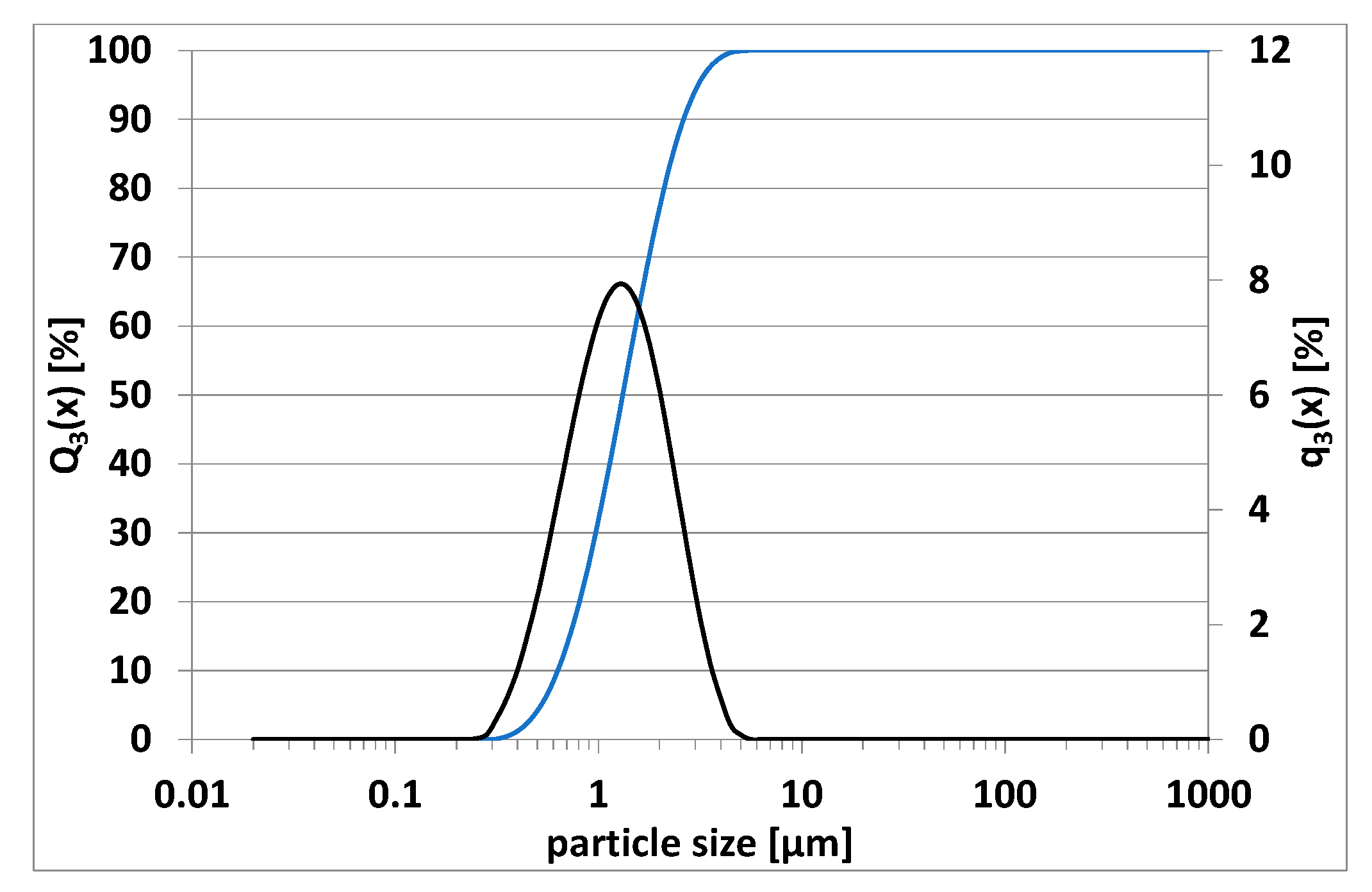
At the beginning of the study, the AlN raw material was investigated. The PSD was measured and can be seen in the following
Figure 1 by plotting the cumulative (Q
3(x)) and density (q
3(x)) distributions.
The result of the powder analysis shows a monomodal PSD with an average particle diameter of d50 = 1.31 µm and largest particle diameter of d100 = 4 µm. In terms of particle size, the AlN powder is thus within the required range for use in the described DLP-based CerAM VPP process and within a component layer thickness of 25 µm. The measurement of the BET surface resulted in a value of 3.66 m2/g, not too high and in expectation of a rather low viscosity, which should be well adjustable using the right dispersants as well as surface additives.
Decisive for the quality of a shaped component are two essential properties of the used photosensitive suspension—on one hand, the flow behavior, preferably determined by the shear rate-dependent viscosity, and on the other hand, the light-induced polymerization of the suspension dependent upon its formulation as well as the applied exposure energy. Both parameters were investigated using various methods (results presented in
Section 3.2 and
Section 3.3) to derive a suitable CerAM VPP setting, which means process speeds (e.g., vat rotation) and the required exposure energy dose for layer-building.
3.2. Viscosity and Flow Behavior of Developed AlN Suspensions
As described in
Section 2.4, the CerAM VPP process based on the Lithoz LCM technology works using a light-transparent vat filled with a photosensitive ceramic suspension, which is coated using a doctor blade to a thin layer of 100 to 400 µm. A schematic representation of the suspension coating and vat rotation situation within the process has been previously described [
35]. For instance, using an average coating thickness of approx. 200 µm at a vat rotation speed of 150°/s is associated with shear rates up to 1000 1/s. Due to that fact, the used photocurable suspension should have a viscosity that varies only slightly in this shear rate range, preferably within 2 powers of 10, to ensure a good layer coating. The viscosity of a suspension for this process should be not too low or too high. In the case of a viscosity that is too low, wettability problems will arise leading to pores within the green and sintered component; a viscosity that is too high will result in low flowability, and the coating of thin suspension layers cannot be guaranteed. Crucial for high-quality components is a homogeneous thin layer achievable through an ideal suspension viscosity. This requires good control of suspension viscosity, especially having a shear thinning behavior at low shear rates (1–10 1/s) [
43,
44].
The developed AlN suspensions of this study are based on a low viscous tetrafunctional polyether acrylate and an aliphatic urethane di-acrylate mixed in a weight ratio of 7:3 and modified using a non-reactive plasticizing fluid. Therefore, only the dispersant and its contents were used to control the viscosity and stability of the developed AlN suspension.
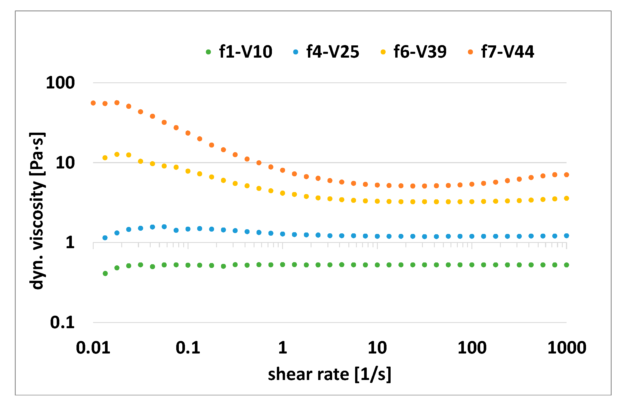
In the first stage, the influence of the AlN content via constant dispersant content was investigated. The result can be seen in
Figure 2 by plotting the dynamic viscosity dependent upon the shear rate in a solid content range of 10 to 44 vol%.
The result shows a Newtonian behavior in a low viscosity level for the suspensions with a low solid content up to 25 vol%. The risk of instability is naturally high here because, without an increase in viscosity at rest, the particles tend to sink down. As expected, increasing the solid content to 39 and 44 vol% resulted in a change to shear thinning behavior and a higher viscosity level, which was up to 80 Pa·s at low shear rates for a suspension of 44 vol%.
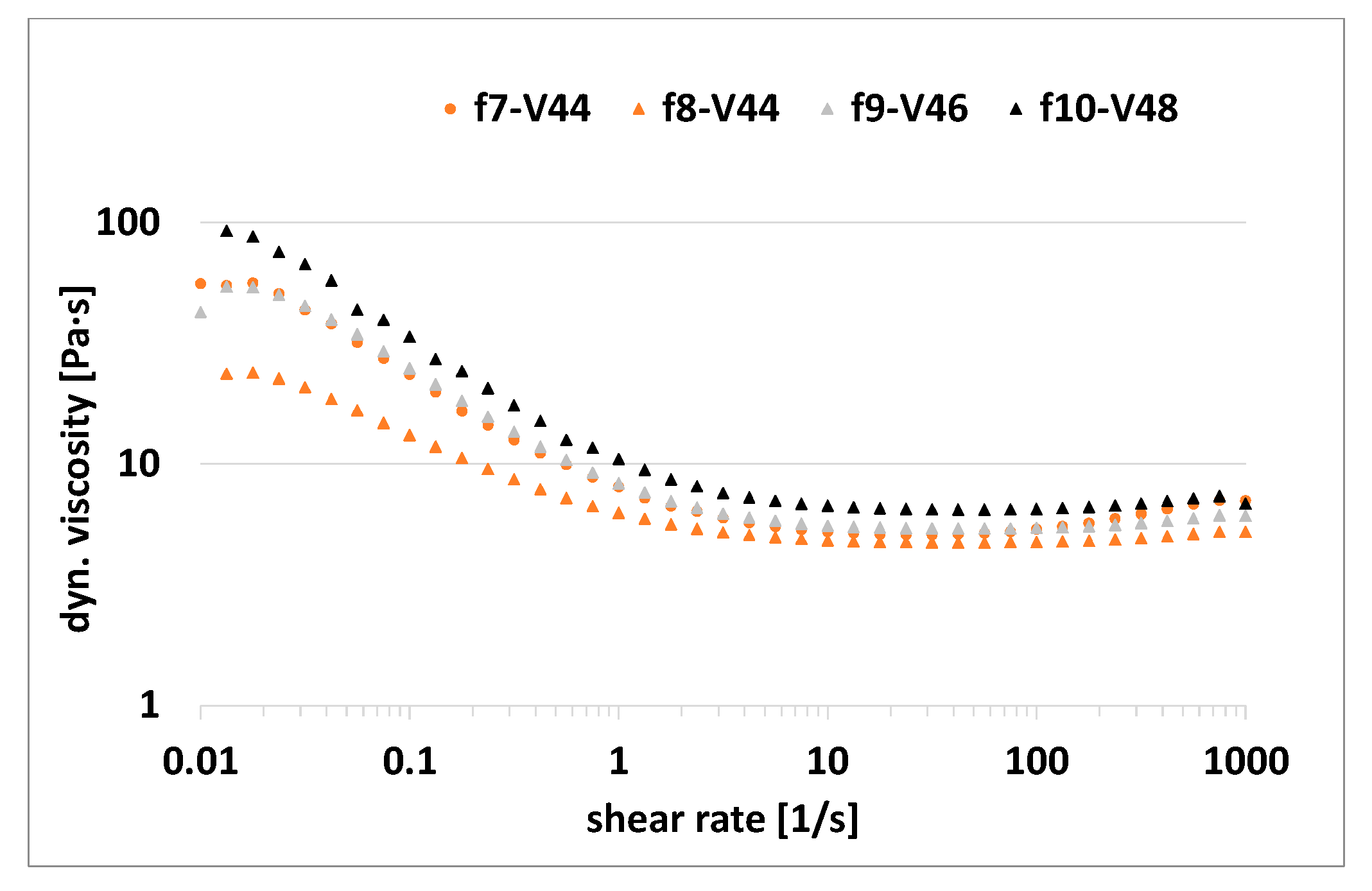
Increasing the solid content up to 48 vol% was the goal in the second stage to achieve a higher green density, which in the end should allow a higher density after sintering. Avoiding a significant increase in viscosity, the dispersant (FD) content was increased at the same time (f8–f10). The result is presented in the following graph,
Figure 3.
By increasing the FD dispersant content from 1.3 (f7) to 1.5 (f8) wt% for a suspension with 44 vol% AlN, a general decrease in viscosity was observed, especially at low shear rates (0.01 Pa·s) with 70 Pa·s to 20 Pa·s. Due to that, it was also expected to achieve low viscosity after increasing the solid contents to 46 and 48 vol%, which was confirmed by the results. The viscosity increased again with the solid content, but remained at a low level, for 46 vol% below 80 Pa·s (0.01 1/s) and nearly 100 Pa·s (0.01 1/s) for 48 vol%.
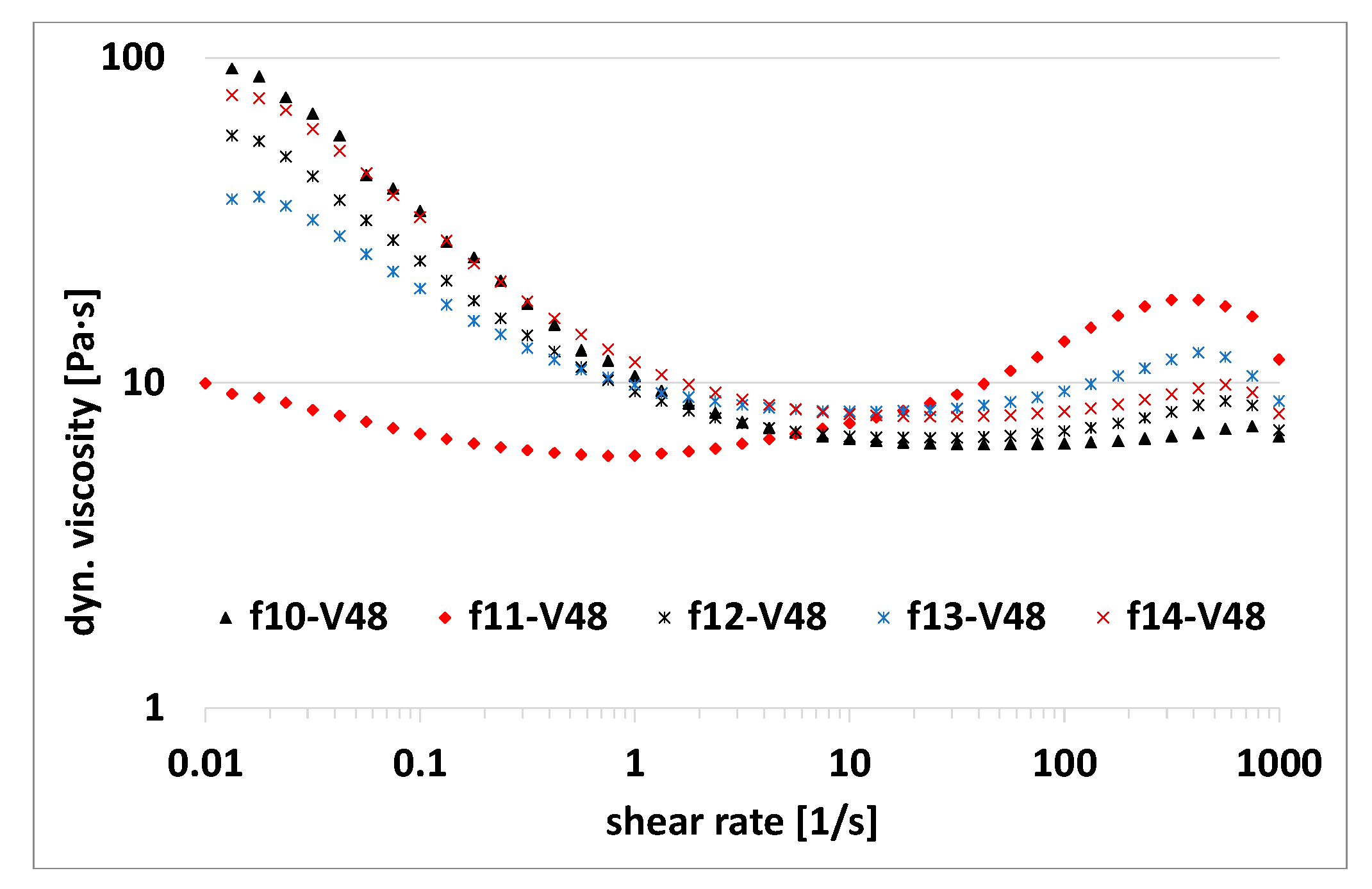
In the third stage of development, it was investigated whether the viscosity could be further decreased at low shear rates. Therefore, an alternative dispersant (AD) was used at first (f11). Afterwards, suspensions with both dispersants were prepared, with the approach to use FD to modify the powder surface and AD as a coupling agent (f12, f14). Three different proportions were investigated, as described in
Section 2.2. The influence on the viscosity is shown in
Figure 4 by the flow curves.
Using the alternative dispersant, the viscosity and flow behavior significantly changed to values below 10 Pa·s at shear rates of 0.01 to 80 1/s. With shear rates above 80 1/s, an unfavorable shear thickening was observed followed by a further decrease in viscosity. The change in viscosity over the shear rate range is unfavorable and should be avoided for a homogenous suspension coating in the vat within the printing process. In previous studies, it was observed that a dispersant system can help to control this behavior. Due to that, three different combinations of FD and AD were investigated. By decreasing FD to 1 wt% and using 0.5 wt% AD, the viscosity at low shear rates was reduced by 20% (f12). At the same time, the viscosity above a shear rate of 50 1/s slightly increased.
A mutual change of FD and AD content (f13) reduced the viscosity by 50% compared to f12, but a shear thickening effect was observed with a further increase in viscosity above a shear rate of 50 1/s. It was assumed that the modification of the powder surface via FD was no longer sufficient. By adjusting the FD content back to 1 wt% combined with 1 wt% of AD, the viscosity of f14 increased again, comparable to f10. In summary, an adjustment of the viscosity is possible to a limited extent when using a system of both dispersants, with f13 as the best of the investigated combinations.
3.3. Curing Behaviour of the AlN Suspensions
Besides viscosity, the most important factor for lithography-based AM technologies is the curing behavior of the photoreactive material. Especially for ceramic processing, good mechanical properties and dimensional accuracy are crucially related to the curing depth, a value mainly determined by the formulation of the photoreactive suspension. Ceramic particles within a photoreactive system act as interference centers and make photo polymerization more challenging. The photocuring light is multiple-scattered by the surfaces of the ceramic particles instead of being led into the depth during exposure, which leads to a decrease in cure depth. Jacobs et al. described the basics here 30 years ago by modelling the cure depth (
CD) using an exponential absorption approach according to the Beer–Lambert law and the manifestation of the basic “working curve” equation of stereolithography (1), a straight-line relationship through a semi-logarithmic plot of
CD vs. ln
E [
45]:
The penetration depth is described by
DP,
E is the energy of the light source and
EC the critical energy for the initiation of polymerization. If light hits a surface, some of the energy is absorbed and some is scattered. Ceramic particles are many submicron disturbances in a suspension, often with a large surface area, which influence and attenuate the transmission of light energy through absorption and scattering. In consequence, the energy per volume available to the photo initiator to initiate polymerization decreases with increasing layer depth [
45,
46,
47].
Excessive scattering can lead to partial overexposure effects during curing, resulting in a loss of process resolution. Controlling the curing behavior is essential to achieve components of high precision. A good empirical range in which the cure depth should be controlled to avoid delamination is given with 10–35% more curing for the thickness of one layer [
43].
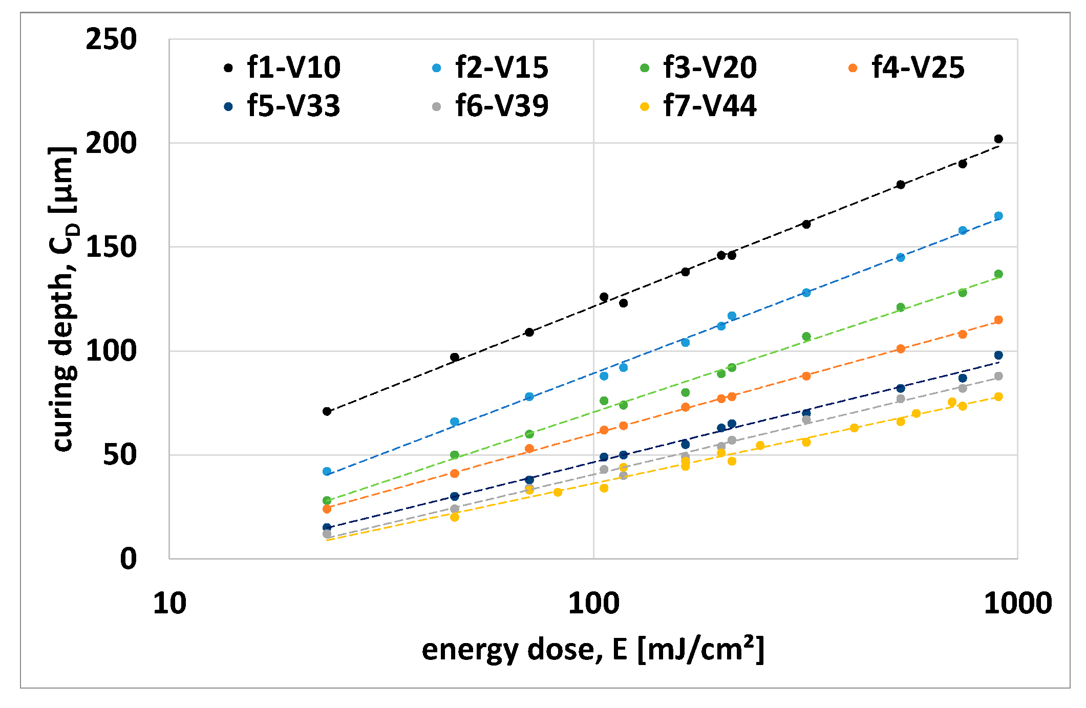
A suitable suspension composition with useable exposure parameters was determined by investigating the relationship between cure depth and suspension formulation, especially AlN content as a function of exposure energy.
Figure 5 shows a semi-logarithmic plot of the cure depth dependent upon curing energy for suspensions of different AlN contents.
As expected, the cure depth decreases significantly with increasing solid loading. For instance, up to a 1000 mJ/cm
2 energy dose for a 10 vol% AlN loading, the cure depth ranged between 75 and 200 µm, and in contrast for a 44 vol% AlN content, the cure depth decreased to a range of 30 to 80 µm. The penetration depth (
DP) and the critical energy (
EC) can be determined based on the measured values. By plotting them against the solids loading (φ) (
Figure 6), the dependence can be shown.
In agreement with Griffith et al. [
48], the penetration depth is inversely proportional to solid loading and decreases linearly. The critical energy dose, on the other hand, follows an exponential function and, in contrast to the penetration depth, increases with the solid content.
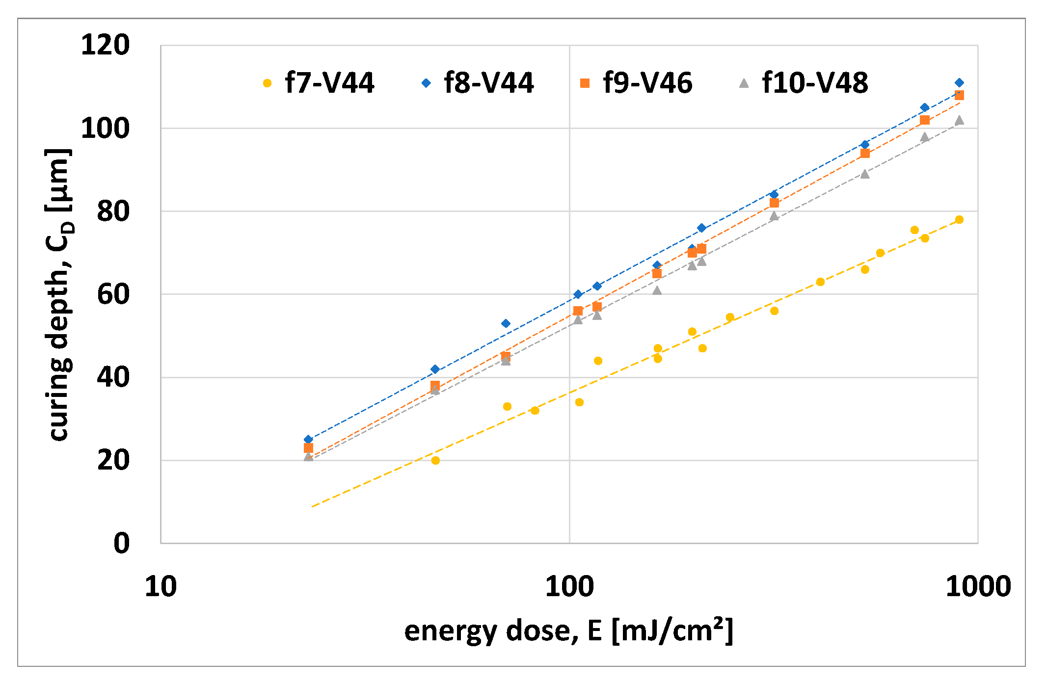
In the fourth stage of development, the photosensitivity was tuned by adjusting initiator content and measuring the cure depths dependent upon exposure energy (
Figure 7).
Known from a previous study [
35], the initiator content influences the curing depth significantly by influencing the penetration depth and the critical energy dose. The achieved cure depth for a solid content of 44 vol% was slightly too low, with 80 µm at a 900 mJ/cm
2 energy dose, as too much overexposure was detected here the same time. An increase in cure depth was necessary to achieve a better layer-by-layer connection during the shaping process without overexposure. By reducing the initiator content of I1 to c = 0.009 mol/L and I2 to c = 0.032 mol/L (other concentrations were also investigated but are not shown), a significant increase in cure depth with a factor of 1.25 to 2.00 dependent upon energy dose was observed. For example, the cure depth at 100 mJ/cm
2 increased by a value of 24 µm from 35 µm to 59 µm. A comparable phenomenon was observed in a previous study [
35]. By increasing the initiator content, at first
DP increased and
EC decreased, but there is an inflection point (IP) for the initiator concentration, and afterwards
DP begins to decrease. Since
DP and
EC decrease after reaching IP,
CD also decreases, but overexposure will increase due to lower energy doses needed for polymerization initiation. In this study it is suspected that the first initiator content was too high, and the value was behind the IP. Due to the reduction of the initiator content in the fourth stage,
DP as well as
EC increased, but in total
CD increased. It is not clear if the IP was reached or not, but it will be clarified in future investigations of various initiator contents.
Suspensions with a solid content of 46 and 48 vol% show a similar behavior, with a small decrease in cure depth at increasing solid contents. Based on this result, a suspension with a solid content of 46 vol%, a dispersant content such as f12, and an initiator content following the results of the fourth stage were chosen for all test samples.
3.4. CerAMfacturing of Test Components via CerAM VPP
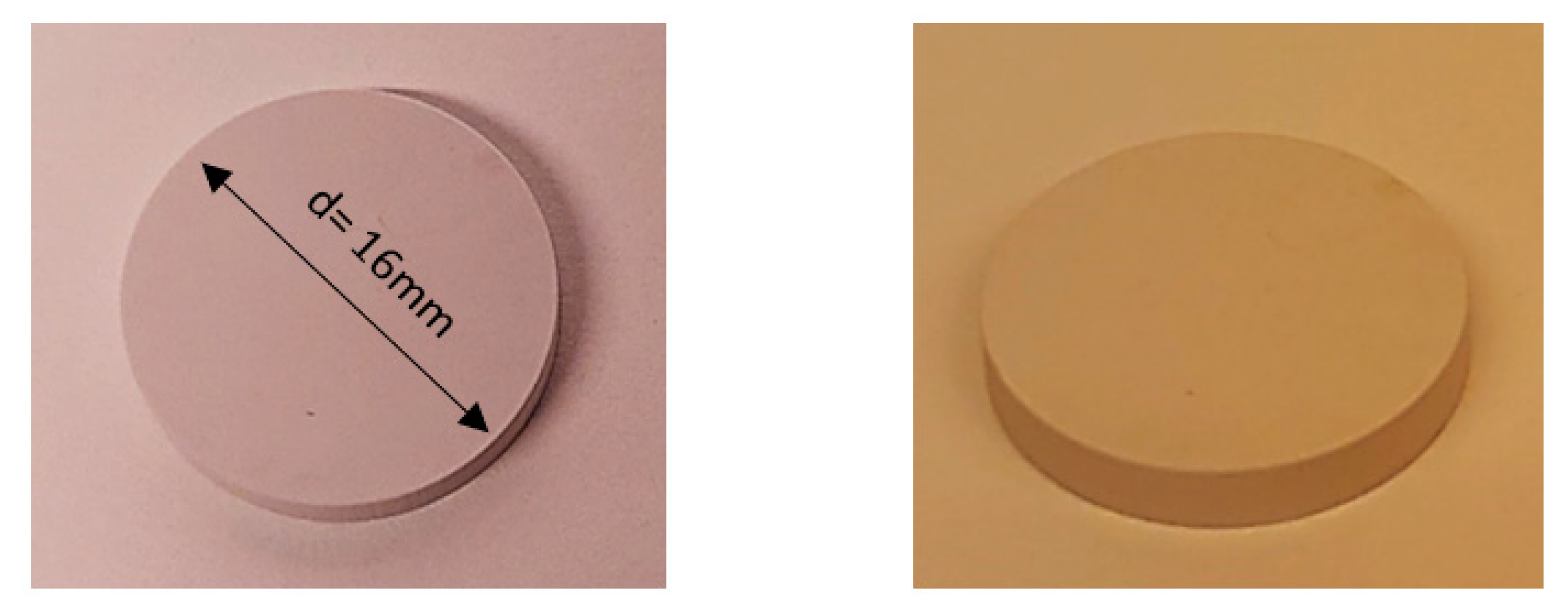
At first, tests bars of 12 mm length (cross section 5 × 5 mm
2) and disc-like samples including shrinkage compensation (green body size: diameter d = 16 mm, height h = 2.76 mm) were manufactured (
Figure 8), with a building layer thickness of 25 µm and an energy dose of 160 mJ/cm
2.
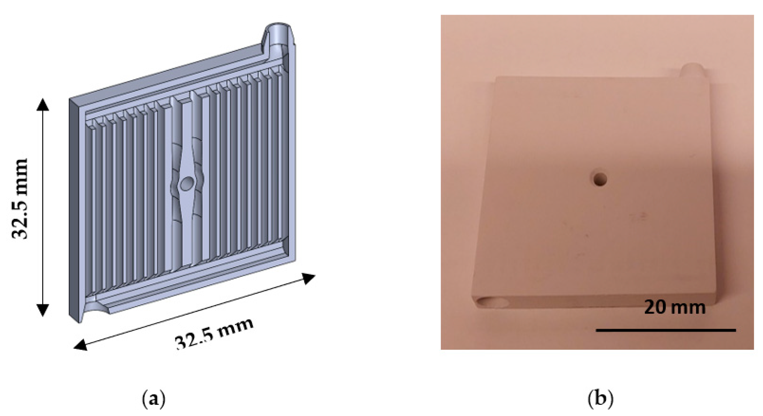
CerAMfacturing of these green discs was successfully achieved using the derived parameters. After cleaning the components with a cleaning solution in combination with pressured air, no defects were detected through visual inspection. Afterwards, substrates with inner cooling channels were manufactured (
Figure 9). Due to a smaller cross-sectional area, a larger energy dose of 200 mJ/cm
2 was used for layer exposure to ensure that each layer would be adequately connected to the green body.
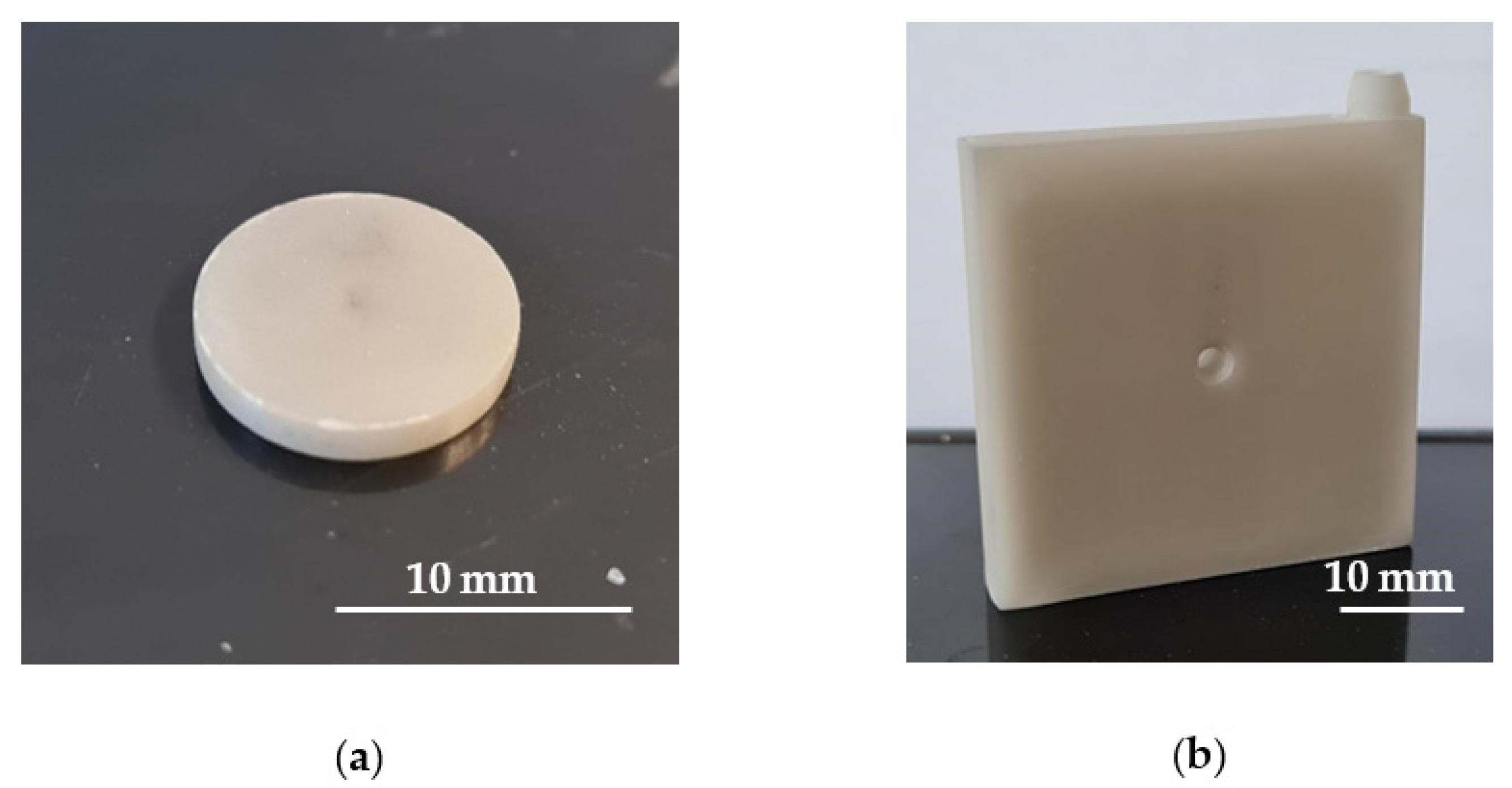
All green samples were cleaned, measured in all dimensions via caliper and then debinded as well as sintered followed the description of
Section 2.4. The sintered components—discs and a complex substrate—are shown in
Figure 10.
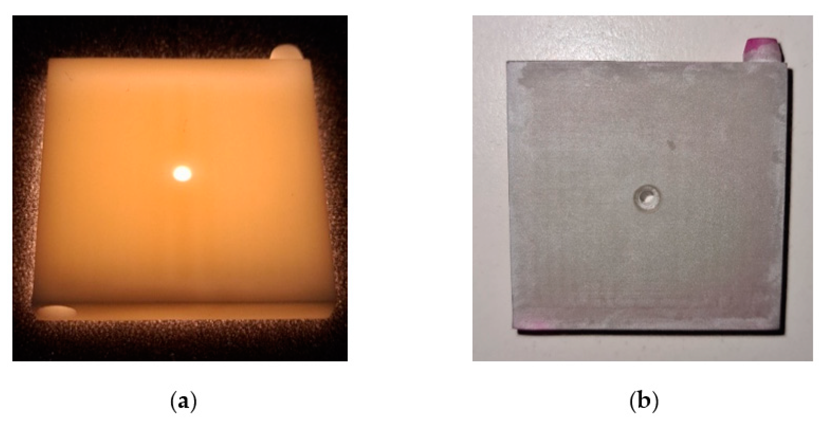
The visual inspection of all sintered samples revealed no obvious defects or cracks, which is a satisfactory result for the development state. The complex substrate with inner cooling channels was also apparently free of defects. Simple fluoroscopy with a lamp was used to screen for defects, but here also no defects became visible (
Figure 11). Additionally, crack infiltration tests (
Figure 11) via color solution (ARDROX-9VF2, BASF) and CT scans were taken to test the results, but they also did not show any defects as a great result.
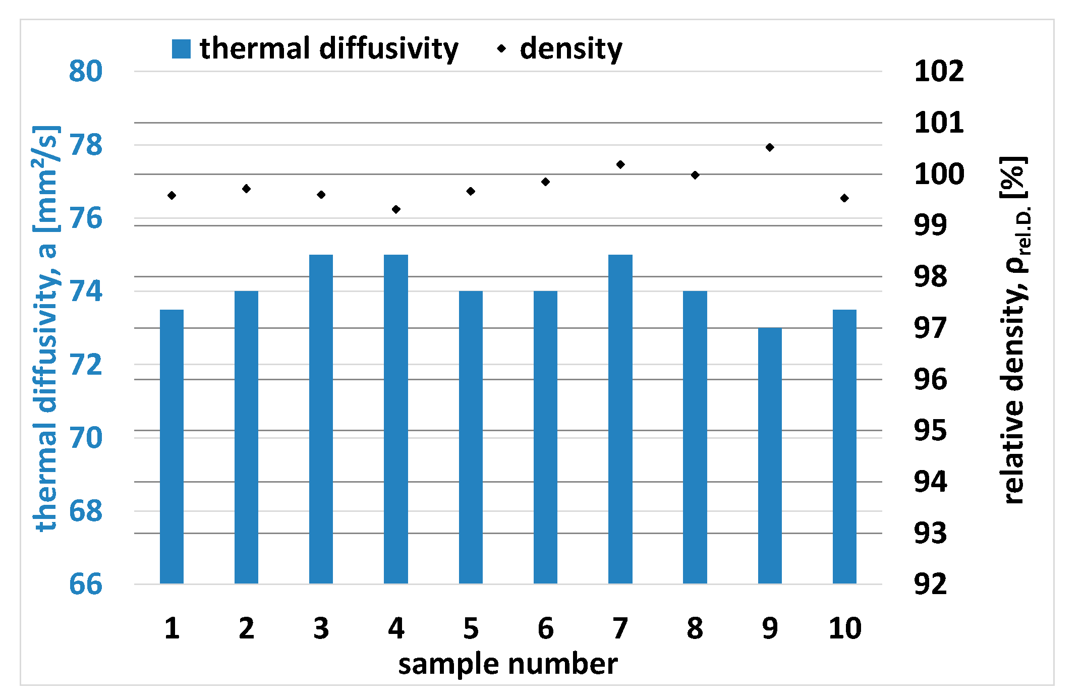
3.5. Properties of Sintered AlN Components
After sintering, the density of 10 samples (discs) was measured via Archimedes’ method, resulting in an average value density of ρ = 3.33 ± 0.008 g/cm
3 (ρ
rel.D. = 99.7 ± 0.33%) for AlN discs. With the same 10 samples, the thermal diffusivity was measured via LFA. Both results, the density and the thermal diffusivity, are presented in
Figure 12.
Based on these results, the thermal conductivity (
λ) was estimated according to Equation (2):
The thermal diffusivity is represented by “
a” in a product with the individual density ρ and the specific heat capacity
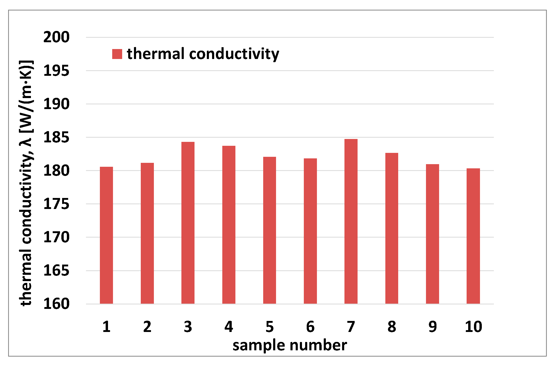
cp (room temperature). The calculated thermal conductivities of 10 samples are presented in
Figure 13.
The measured thermal diffusivity reached very homogeneous values, in a range of 73 to 75 mm2/s, and therefore, in combination with the measured density, led to thermal conductivities with an average value of 182 ± 1.5 W/(m·K), a very good result for AlN corresponding to the powder supplier’s specifications for pressed components.
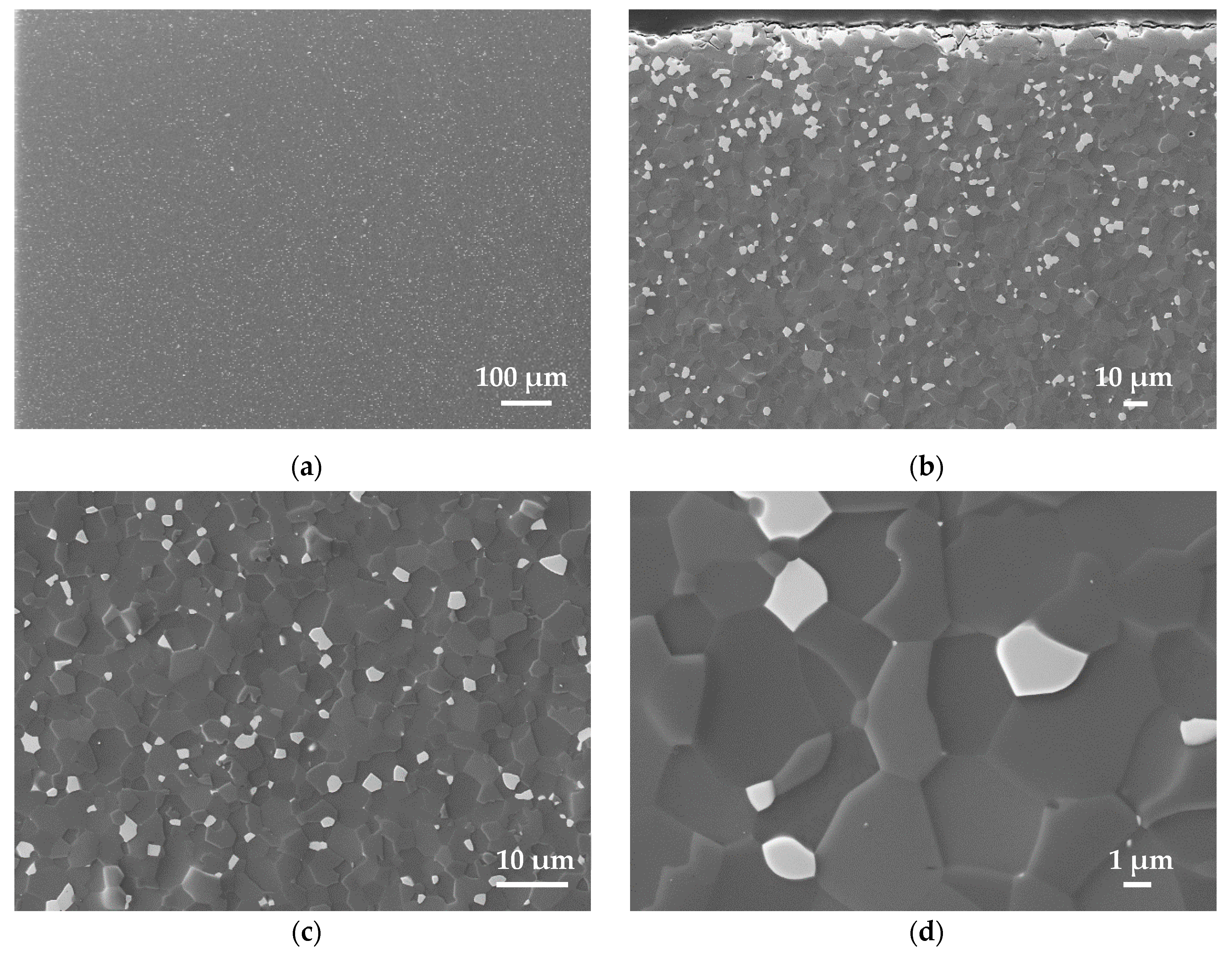
Supporting the results of the achieved densities as well as the thermal conductivities, the microstructure of a polished cross-section of a sintered disc was analyzed via FESEM (
Figure 14).
The AlN components were heated through a standard program using a constant heating rate of 5 K/min up to 1840 °C with 4 h dwell time. In general, the images show a homogeneous AlN microstructure. The secondary phase (yttria) can be distinguished from AlN by its brighter contrast (white grains). Clusters of them could not be found. All microstructures confirmed high densification as evidenced by well-developed polyhedral AlN grains. In the direction of the sample surface, the yttria amount increases and forms a kind of boundary layer in which the yttria content seem to be higher compared to the main part of the structure. During sintering, the yttria tends to excrete on the surface. However, this is intentional to achieve a high thermal conductivity over the entire structure. In general, the microstructure of the sintered AlN shows a good quality, comparable standard AlN, especially created through conventional shaping. A layered structure could not be identified.
4. Conclusions
Meeting the constantly increasing demands on substrate materials and heat sinks resulting from the permanent increase in power density, and thus also in heat generation in electronic components, new types of components made of high-performance materials with highly complex geometries are required. AlN is predestined as such a material because it has a unique combination of high thermal and very low electrical conductivity.
In this work, AlN has been successfully qualified as an AM technology. Based on a commercial powder, the suspension and process development for CerAM VPP was carried out, which is a DLP-based vat photo polymerization technology, to realize sintered components with excellent thermal properties and comparable achieved values of conventional shaping methods (approx. 180 W/(m·K)).
Photoreactive suspensions were developed, and the influence of the AlN content up to 48 vol% on viscosity and photosensitivity was investigated. Afterwards, the flow and curing behavior were slightly optimized using a dispersant system and an adjustment of the initiator content.
Based on the results of the suspension characterization, CerAM VPP process parameters for the CerAMfacturing of test components were derived. Test components with different geometries were CerAMfactured, debinded and sintered.
The properties of the components were characterized along the entire process chain. The achieved densities of 3.33 g/cm3 (ρrel.D. = 99.7%) and thermal conductivities larger than 180 W/(m·K) are excellent and comparable to state-of-the-art for conventionally manufactured components. The microstructure is homogeneous and of good quality, confirming the measured density and thermal conductivity.
A substrate with a complex inner design of cooling channels was used to demonstrate the successful CerAMfacturing of complex AlN components. Further work and publication will address AlN components with application-specific designs as well as the mechanical characterization of AlN components.


