1. Introduction
The positive effects on workers’ mood and their well-being brought by the awareness of being in a safe working environment have been demonstrated by different works present in literature (e.g., Fung et al. [
1]) and actually acts as a good booster to the avoidance of accidents.
Every working environment should guarantee safety to employees and operators both in normal operations and extraordinary duties (e.g., maintenance operations), however, the industrial domain is one of the fields in which it is more important due to the risk at which each worker is exposed.
During the last decades, different solutions already contributed to the enhancement of the sector, and thanks to the introduction of new concepts like the “Industry 4.0” one has drastically changed how plants and factories are designed and operate all around the world.
Nonetheless, based on the performed state of the art analysis reported in the related works section, at the moment of writing, the literature is still lacking an effective intervention in one of the most dangerous activities which is the maintenance of machinery in industrial plants. Based on the last statistical surveys, maintenance is still prone to a lot of accidents that have to be addressed in the future of safety engineering [
2].
The workers’ safety during maintenance activities, especially in huge plants, depends on the correct execution of complex procedures, the correct training of the operators, the effective supervision during the execution, etc. Furthermore, in addition to the inherent dangerousness of maintenance activities, nowadays such operations are often performed by third parties’ employees, that, unfortunately, are not experts in the specific machinery they are going to maintain and usually have limited knowledge of the possible production problems and possible causes of severe injuries. Moreover, also from a legislative perspective, during maintenance activities of industrial environments generally workers are subjected to risk reduction necessity at the organizational level in accordance with the provisions of the legislation of health and safety of workplaces, Directive 89/391/EEC, 1989 [
3].
One of the paradigms that, in our opinion, can play an important role in making maintenance activities safer is the Internet of Things (IoT). Although the machineries already integrate systems and solutions to guarantee safety during their normal operation, they cannot guarantee the same safety level during maintenance simply because such systems are usually off during maintenance. Instead, the IoT and its multitude of autonomous small devices can act as a promoter to monitor and intervene in the operations performed during maintenance activities.
Although maintenance scenarios can be really complex and heterogeneous, the most important situations that are always present in almost all the maintenance procedures are summarized in the following list of actions that an operator has to sequentially perform during his/her duties: (a) de-energize systems before maintenance, (b) verify that there is not any other operator in the hazard zone in which he/she has to operate, (c) follow the procedures designed by the machine builders for correctly maintain the machinery, (d) verify that all the performed actions brought to the correct working of the machinery, and (e) re-energize the machinery itself.
All these procedures are usually regulated by various directives and laws. E.g., the machinery-worker interaction is designed by the machine builder that has to fulfill the safety requirements of Machinery Directives 2006/42/CEE, annex I [
4]. As a further example, the problem of the unexpected start-up of an axis of the machine during maintenance activities or the necessity of switching off the power before starting the maintenance are typically devised by the de-energization of dangerous devices as required by the safety requirements in the same Annex I (clause 1.6.3 “Isolation of energy sources”). In addition, the safety minimum levels (e.g., the safety stop and the safety reduced speed functions, the proper safety integrity level (SIL), and the Performance Level (PL)) should be calculated with a given standard that depends on the machine type or by architecture used for the implementation [
5,
6]. Furthermore, the modification of the machine or its correct maintenance procedure without the explicit authorization of the manufacturer involves the need to re-mark the machine by the third parties who make changes.
However, despite all these laws and regulations, based on the performed literature analysis reported in the related works section, at the moment of writing, the complete and regular respect of the reported procedures is not completely supervised by comprehensive ecosystems able to monitor all the hazard situations and notify the right people in case of problems. In this context, the project reported by Buffi et al. [
7] aims exactly at realizing a smart system based on IoT technologies to enhance worker safety in maintenance procedures.
This paper presents the architecture of the innovative system designed within the project. It aims at guiding operators step by step while real-time monitoring the plant, the machine, and the other employees working in the same area. During the maintenance procedure, the operator is guided in the proper execution of each maintenance step and an autonomous IoT system monitors the status of the different parts of the plants and machinery to, then, authorize and show the next steps foreseen in the maintenance process. Within the present paper, a prototype of the system has been implemented to evaluate its feasibility and effectiveness of the system.
Various works already presented solutions to support industrial plants maintenance by making predictions on various aspects and operations as demonstrated in the related works section, but they have not been effective in supporting operators, administrators and supervisors throughout their maintenance activities to prevent “reasonably foreseeable misuse” of the plant or the machinery that they have to maintain through the exploitation of IoT sensors and other technologies fully integrated with the machinery. It represents the main innovative contribution of this paper that presents an innovative system able to guide the operators during their work, let them chat with experts, and be fully integrated with the machines to, then, generate alerts in case of dangerous situations.
The rest of the paper is organized as follows:
Section 2 describes the regulatory normative about risk reduction and the standards in machinery taken into consideration throughout the current work.
Section 3 presents the related works that inspired the definition of the Requirements and the Running Scenario reported in
Section 4. Then,
Section 5 presents the proposed system architecture and
Section 6 reports the implementation of its different modules. In
Section 7, the definition of a real procedure faced by a maintenance operator is exploited to describe how the system works and, therefore, how each component acts in a real situation. Furthermore,
Section 8 discusses the main benefits brought by our proposal, and, finally, we present conclusions and recommendations for future works in
Section 9.
2. Industrial Regulation
The most critical factor to be addressed for guaranteeing workers’ safety is the reasonably foreseeable misuse of machineries and tools as defined in MD 2006/42/CEE, annex I, Definition 1.1.1, that shall be covered in all the machines sold and installed in EU: with the term ‘reasonably foreseeable misuse’ we intend the use of machineries in a way that was not foreseen during its construction and, therefore, not reported in the manual, but which may be predicted from readily predictable human behavior. Same similar regulations are not only foreseen by the EU, in fact, they are also present in almost every country of the world due to their importance.
Based on the literature, it is difficult to define in practice the “predictable human behaviors” but at least some “dangerous” behaviors are defined in ISO 12100:2010 [
8] that is the type A standard for the risk reduction in machine directive.
The ISO 12100:2010 standard gives the following examples of the kinds of misuses or readily predictable human behaviors to be taken into account: (a) loss of control of the machine by the operator; (b) reflex behavior of a person in case of malfunction, accidents or failure during the common use of the machinery; (c) behaviors resulting from lack of concentration or carelessness; (d) behavior resulting from adopting the line of least resistance in carrying out a task (e.g., a given machinery is designed with redundant safety devices and, as a consequence, the worker removes/disables the safety devices to work faster thinking that they are not important); (e) behavior resulting from pressures from the bosses to keep the machinery running in all circumstances; (f) the behavior of specific kind of people such as children. All these behaviors can be partially or fully foreseen during the design of machineries, however, if the machine is off or in maintenance mode there is no way to act with the proper countermeasures.
Moreover, as already anticipated, during maintenance operations various third-party workers are usually responsible for the maintenance activities, but they may be not sufficiently aware of the system or the machinery they are maintaining. Therefore, in normal conditions, such operators need special training for maintenance on the particular machinery, while, if a system like the one we are proposing, can guide them throughout all the operations, the training can have a lower impact on the preparatory activities (and therefore on the funds spent by the company).
An alternative to an automatic monitoring and acting system is to have a tutor per each operator, that is a second dedicated worker that follows step-by-step the third-party maintainer. Such a tutor should be an expert that is completely aware of the control station of the specific machinery under maintenance. However, such a solution may result in the exploitation of modified maintenance procedures that are not in line with the instructions designed by the machine builder (e.g., typically, the presence of more than one operator is not allowed by the machine builder, especially for large machinery).
Typically, those problems are managed with LockOut/TagOut (LOTO) procedures [
9], some safety procedures used to ensure that dangerous equipment is properly shut off and not able to be started up again prior to the completion of maintenance or repair work. The application of these procedures usually results in the segmentation of the working area into different “LOTO points” in which the operators are asked to de-energize relevant devices and lock energy sources with real locks and keys that can be removed only by maintenance workers; however, such solutions may introduce latency in the execution of the procedures and/or further effort in preparing operators.
3. Related Works
Various works presented in the literature present solutions to support industrial plants maintenance by making predictions on various aspects and operations (e.g., [
10,
11,
12,
13,
14]), but based on the regulations presented in the previous section, it is more important to support operators, administrators and supervisors throughout their maintenance activities to prevent “reasonably foreseeable misuse” of the plant or the machinery that they have to maintain. To this aim, various works in the literature (e.g., [
15,
16,
17,
18,
19,
20,
21,
22,
23,
24,
25]) already faced the problem by proposing different solutions to mitigate the mentioned problems. Nonetheless, to the best of our knowledge no works face the problem of assisting operators through the exploitation of IoT sensors and other technologies fully integrated with the machinery, able to guide the operators during their work, let them chat with experts, and be fully integrated with the machines to, then, generate alerts in case of dangerous situations. Therefore, this section presents the most important artifacts that propose technological solutions to monitor and guide operators during their maintenance activities although they are not fully integrated. As reported by Palmarini et al. [
26], most of the related works are mainly focused on the application of Augmented Reality (AR) techniques to detect the performed operations and help operators through various feedback (e.g., haptic gloves).
The first interesting work focused on the exploitation of AR techniques in maintenance operations is the one presented by Vignali et al. [
15] that proposes an AR solution to enhance the safety of employees. Differently from the present work they do not use any IoT device to monitor the presence of the operator or to detect the status of the machine, like we do in this work. In addition, the system does not guide the operator, while it is the operator who guides the operations. Alam et al. [
16], instead, propose a modular architecture to assist and protect workers in the work environment from some hazardous elements. Their proposed system leverages video acquisition, Head Mounted Display (HMD), and wearable devices to monitor the environmentand send warnings in case of hazardous conditions concerning the air. Although they use IoT devices and sensors, they do not face the problem related to the movement of people in the maintenance area and do not prevent related emergencies. Other two interesting works are the ones proposed by Verde et al. [
17] and Smith et al. [
18] that presented two similar systems for a remote assistive maintenance intervention based on AR systems. Based on the description, the systems leverage only vision-based methods and techniques without additional IoT sensors and systems to trace the operations of each operator and do not guide the operators step-by-step. Gong et al. [
19] present a framework for developing extended reality (XR) systems within manufacturing context. The framework have been validated through one empirical case and seven identified previous studies and contributes to the provision of a clear guideline on the steps needed to integrate XR in manufacturing with increased usability and user acceptance. Bottani et al. [
20], instead, works on the machine level by forwarding machine alerts to the operator’s smartphone and then providing the instructions needed for solving the detected alarm. In this case, the machinery can generate notifications as our system performs. However, no IoT sensor is used and no step-by-step support is provided.
Despite the strong presence of AR in almost all the solutions proposed to address the issue, there are a few works more similar to the present one.
One of them is presented by Vignali et al. [
21]. It presents the “W-Artemys” project that aims at creating technological support to increase employee safety during operations on machines through a dedicated software combined with an AR solution built to handle all the information coming from machines manuals and give the operator an interface to dynamically consult the manual on a dedicated Graphical User Interface. Their work does not deal with the problem related to the movement of operators in the maintenance area and, consequently, does not prevent related emergencies. Another interesting work is the one proposed by Burova et al. [
22] that exploits AR simulation in Virtual Reality (VR) coupled with gaze tracking to enable resource-efficient AR developments. Although the authors do not provide a solution to directly monitor the safety of the workers, their output highlights the importance of treating worker safety already in the design process and proposes the usage of AR simulations for this purpose. Such a best practice guided the design of our system. The system proposed by Kanan et al. [
23], instead, works more on the machine and its ability, through some dedicated sensors, to prevent hazardous movements of the machinery with respect to any other stakeholder present in the same area. The proposed system is more focused on communications among the components. Finally, the works proposed by Kim et al. [
24] and Gorli et al. [
25] propose two safety management systems based on IoT which can be operated at a low cost not only at large construction sites but also at smaller construction sites.
4. System Requirements
4.1. Requirements
The most important regulation related to the design of safety machine tools is the already mentioned ISO 12100:2010 [
8]. In particular, Section 5.3.1 of the regulation reports that “Risk assessment begins with the determination of the limits of the machinery, taking into account all the phases of the machinery life. This means that the characteristics and performances of the machine or a series of machines in an integrated process, and the related people, environment, and products, should be identified in terms of the limits of machinery” and, therefore, have to be taken into account in designing new safety machines. Specifically, the limits to be respected in using any machinery are reported in Section 5.3.2 of the regulation, and the ones related to the safety of workers during maintenance are discussed at point c. At this point, it is specifically requested that the training level of maintenance personnel has to be always taken into account. In addition, as reported in point 5.4 of the regulation, hazard identification has to be performed and hazardous situations have to be taken into account, as listed in Section 5.4 (a).
Guided by the just mentioned state of the art and all the other relevant standards applied for this kind of risk analysis, we have elaborated and extracted the following list of requirements to enhance worker safety in maintenance procedures. The first list reports the main functional requirements (FR) that guided the design of the proposed system architecture, while the second list reports the non-functional ones (NFR). The system should: FR1. be always connected to the machinery through a smart system complaint with MD 2006/42/CEE. This requirement is extracted from EN 62745:2017+A11:2020 [
27] that is the standard to be respected to guarantee the safety of machinery and, thus, contains a lot of specifications related to operating command signals such as neutral frames (Definition 3.10) and valid signals (Definition 3.21). The specific part from which the FR1 has been extracted is the one related to the cessation of transmission from the remote station that shall cause an automatic stop command for the machine. This mandatory rule generated both the requirements and the consequent countermeasures designed for our system. FR2. be able to verify that the system is in safe mode before allowing any maintenance operation. It is derived from the specification reported in the standard ISO 12100:2010 [
8], paragraph 6.2.11.10: machinery with service mode shall be provided with a mode selector which can be locked in each position/location. The physical selection of service mode enables input signals to the safety-related part of the control system as defined in ISO13849-1 [
5]. FR3. guarantee support to de-energize and re-energize the machinery before and after the maintenance. The de-energization of any machinery before any maintenance activity declined in the LockOut/TagOut procedure is one of the specifications reported as a specific measure to be performed in disconnecting the machine from the power supply. It can be found in standard ISO12100:2010 [
8] paragraph 6.3.5.4, Measures for isolation and energy dissipation. FR4. monitor the position of operators concerning some specific LOTO points. At the time of writing, the verification of the correct execution of each procedure is delegated to the visual inspection of the operations and the self-responsibility of the operators. However, it is not always easy to visually inspect operators’ actions, especially in huge industrial plants. Therefore, the monitoring can be appreciated by all the stakeholders. FR5. guide the operator throughout all the foreseen operations; each step should be enabled only if the previous one was successfully completed. The motivation behind this requirement resides in the current state of the art: the current regulations only require to adequately inform the operators about the procedure to be followed and each foreseen step, therefore there is no live control of the real performing of each operation and it is always difficult to guarantee their respect. This requirement is linked with FR9. FR6. allow the acquisition of messages from the machinery (when it is on). This requirement is, instead, derived from the needs highlighted by the analyzed related works.
On another hand, all the following requirements (from FR7 to FR10) have the same motivation and are derived from the same need of innovating the measures currently used to guarantee the respect of all the rules and security procedures, as reported by the EU commission staff working document on Health and Safety at Work is Everybody’s Business [
28] that recommend a modernization of EU occupational safety and health policy, tools, and legislation. In fact, at the moment of writing, as stated by [
2], all the following requirements are fulfilled simply by providing written procedures and their satisfaction is only a duty of the operator who is supposed to be responsible for following every rule. Consequently, a system able to guide and support these operations shall be welcomed. Furthermore, the domain in which the works operate hardly influences the requirements themselves and the following list focused on the industrial plants has been inspired by the OiRA sectoral tools web platform [
29] that is the result of a European project and provides information on risk analysis tools for workers specialized on specific risk assessment. FR7. allow the operator to perform tests on the machinery within the maintenance process. FR8. allow the operator to have realtime communication with the supervisor during maintenance. FR9. guarantee to administrators and supervisors to define the steps of each procedure and, then, monitor, in real-time, the correct execution of all the steps. FR10. be able to promptly notify dangerous situations to all the workers involved in the maintenance procedures.
In addition, we have extracted the Non-Functional Requirements to be guaranteed by a safety-dedicated system from the review reported by [
30] that presents the software systems’ quality attributes, i.e., Non-Functional Requirements, that are mostly treated by software architects and developers. Starting from their analysis we have identified the Non-Functional Requirements that are most important in a system that aims at guaranteeing safety in an industrial environment. The following list summarizes all of them. NFR1. Security: The system should assure that all the manipulated data and the interactions among each component of the system are protected against malware attacks or unauthorized access. At the time of writing, the official regulation standards lack specific rules dedicated to security measures to be taken into account in designing safety machine tools, and, in fact, it is going to be introduced in the new version of the dedicated Directive. NFR2. Usability: The system should expose user-friendly interfaces to improve user experience and facilitate the exploitation of exposed services during critical situations. It is a really important requirement that interferes with the acceptance of innovations by the workers. NFR3. Performance: The system should guarantee the reactivity of the whole infrastructure to allow prompt interactions and instructions for and with workers. NFR4. Reliability, Availability, and Maintainability: The system should be able to expose services without failures and guarantee minimum recovery time. NFR5. Scalability: The system should support the increasing number of pieces of machinery and operators.
4.2. Running Scenario
Before entering the details of the designed architecture, we would like to introduce a running scenario to help readers understand the main actions that an operator can perform during a maintenance procedure.
Let us suppose that an administrator noticed some troubles in the normal operations of a machinery and scheduled a maintenance intervention for the operator named Andrea. Therefore, on a normal working day, Andrea arrives at the industrial plant and, after wearing all the safety clothes, he takes his smartphone, and he finds a notification saying that a maintenance intervention was assigned to him. Consequently, he opens the dedicated application and accept the assignment. After that, the application starts to guide him in the maintenance procedure. The first step is to reach the machinery and demonstrate his presence near a LOTO point, the one in which he can de-energize the machinery. So, when he is near the LOTO point, the system recognizes his presence through the continuous monitoring performed by dedicated sensors and asks him to move his smartphone near a dedicated sensor. When the presence of Andrea is verified, the system communicates with the machinery and, after some verifications, allows and suggests to Andrea to de-energize the machinery. Then, Andrea performs the suggested actions, and, after some other verification of the system, Andrea will be allowed to end the first step through a dedicated button in the app. Afterward, the system will suggest Andrea to go to the next step, and by following steps similar to the previous ones, Andrea is guided in the exploitation of the second maintenance step. The procedure continues until Andrea successfully accomplishes all the steps and presses the button to conclude the procedure (de-energization included).
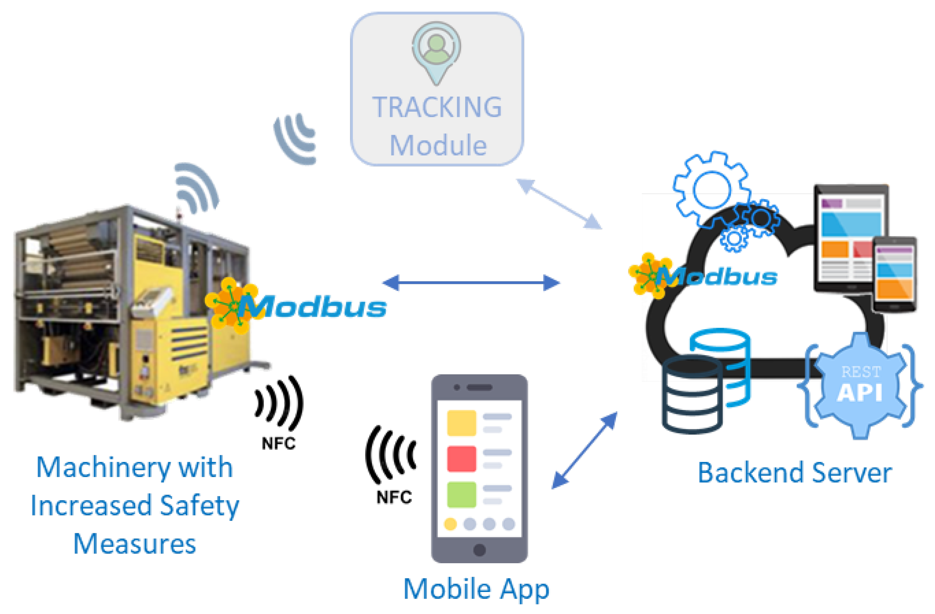
5. System Architecture
Starting from the exposed requirements and inspired by the reported running scenario, the architecture reported in
Figure 1 was designed. The architecture is made by different modules that interact with each other through various interfaces.
The first component is the Tracking Module that is responsible for verifying the position occupied by the operators with respect to both the machinery and also each other single module of the machinery. This autonomous module continuously monitor the presence of operators in the area (identified by specific devices called tags), and interacts with the Backend Server via an Internet connection to: (a) receive the list of the tags associated to each stakeholder, (b) receive the information about the shape/geometry of the machinery and its LOTO points, and (c) exchange the updated status of the position of operators in the monitored areas of the machinery.
The second component is the Machinery with Increased Safety Measures (MwISM). As anticipated, the maintenance of a single MwISM foresees different consecutive steps and the first one regards its de-energization. Therefore, the MwISM has to interact with the system to let operators, supervisors and administrators be sure that all the de-energizing operations are performed in the right way before the next maintenance steps. In addition, it has also to support the system during the re-energization process and during test phases, if needed. A further element of the MwISM is an innovative separate mode selector enabling a special safety system that guarantees workers safety during maintenance through some specific devices. Thanks to such safety system, the machine is able to: (a) monitor potential stored energy as required by LOTO procedure, e.g., to control the pressure of incoming pressurized air and send the data to the application supervisor when the smart service selector (see FR2) is on; (b) allow some movements of the machinery components to maintainers without any interaction with the control system of the machine; (c) autonomously control in real time hazardous movements of the machine during service operations. A detailed description of the machinery prototype is outside the scope of the paper and will be omitted for patent pending confidentiality reasons.
The third component, instead, is the Mobile App. It is an application to be installed on the operators’ smartphone and will allow: (a) the receipt of notifications when a new maintenance is assigned to him, (b) view all the maintenances assigned to him, (c) start the de-energization procedure, (d) communicate the successful execution of a specific step of the de-energization procedure, (e) guide the maintenance operator in all the operations, and (f) provide a live technical chat to ask for technical assistance. In addition, as a further security measure, the Mobile App will exploit the Near-Field Communication (NFC) technology to recognize the presence of an operator near the LOTO point in which he is declaring he is when starting a step of the procedure.
The last component is the Backend Server. It is the core module of the architecture and is responsible for: (a) exposing the necessary REST Application Programming Interfaces (API) to accept inputs from all the other components, (b) store in a database all the data received from the various components, (c) interact with the machinery, (d) expose a dashboard to support the admins and supervisors in their duties (i.e., definition and assignment of maintenance, support the operators through a dedicated chat, etc.), (e) provide an interface for the interaction with the MwISM and, finally, (f) provide support for authentication and authorization.
6. Implementation Details
With the aim of verifying the fulfillment of all the collected requirements and the feasibility of the designed system, a prototype of the proposed environment has been implemented and functionally tested. Therefore, this section presents the details of the implemented prototype.
The first element of the architecture presented in the previous section is the Tracking Module whose responsibility is to verify the position occupied by the operators with respect to both the machinery and each single part of the machinery. It is an autonomous block, described in [
31], that exploits the RFID technology, one of the most frequently used technology in the industrial domain [
32] and interacts with the Backend Server for estimating the position, however it is not part of the present work, therefore, we will not discuss the implementation details in the present paper.
The second block is the MwISM that is, as already mentioned, responsible for supporting the system throughout the de-energization, test and re-energization processes. Due to its importance and with the aim of testing both the provided functionalities and its effectiveness in real industrial plants, we decided to implement two different prototypes: one prototype is a simulator of a machinery and was implemented with a fast-prototype board, i.e., a Raspberry Pi 3A+ [
33], while as a second prototype we used a real turning machine with an industrial CN and industrial safety control devices. The first prototype was developed by using a Raspberry Pi 3A+ [
33] and implemented as a re-elaboration of the “PyModbus” module [
34]. A picture of the implemented prototype is reported in
Figure 2a. As depicted in the picture, two different devices are exploited: the DHT11 temperature and humidity sensor [
35] was used as input and connected to port n. 4, while a 5 V DC electric motor was used as output and connected through a motor driver (connected to ports n. 17, 22 e 27). The driver was powered by a 9 V battery while the DHT11 sensor was powered by the Raspberry Pi itself.
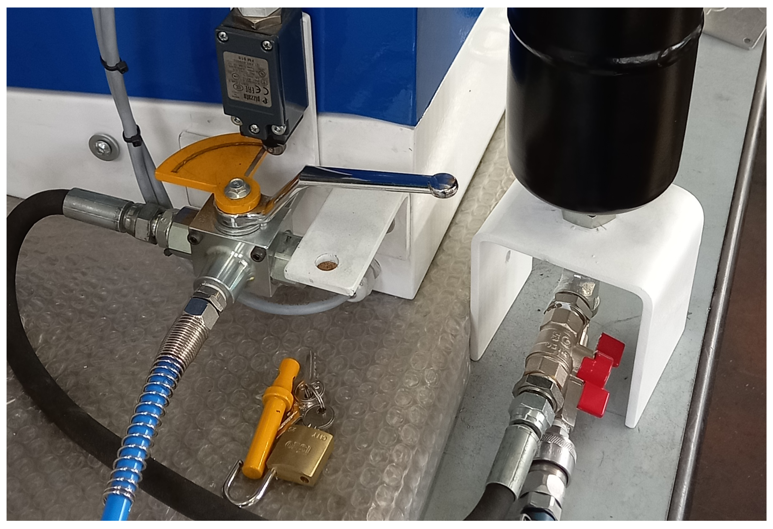
Although the first prototype allowed to validate the protocol implementations and the communications with the other blocks of the architecture, actually satisfying most of the requirements reported in the previous sections, to fully address the requirements more related to real production plants (like FR1), we decided to also introduce a second prototype of the MwISM: the real turning machine shown in
Figure 2b. For this purpose, a real turning machine with an industrial CN and industrial safety control devices was fully implemented and integrated in the system. The detailed description of the machinery prototype is outside the scope of the paper and will be omitted for patent pending confidentiality reasons, but it is composed of three main parts: control station (right side of
Figure 2b), mechanical part of machinery (left side of
Figure 2b) and electrical cabinet (not shown in
Figure 2b). In addition,
Figure 3 shows a zoom of the mechanical part of the machinery in which it is possible to depict the component dedicated to the insertion of a mechanical lock to lock relevant energy sources (to achieve the usual LoTo procedure). Furthermore, the machinery has been equipped with an innovative “Smart Service Modal Selector” (SS) (as required for any mode by MD, Annex I, par.1.2.5 [
4]) that enables the safe connection of the machinery to the entire system that is not shown in the figures due to patent pending reasons. Using the under patent system, enabled through the SS, the maintenance operator is able to interact with the MwISM through the system and move only the axes required for the current maintenance. The control station of the machine is disabled and a limited set of axes movements can be done through the smartphone connected to the system.
Considering that, based on the review presented by Hsiao et al. [
36], one of the protocols most frequently used by Industrial machineries for communicating with each other and with other systems or components is the MODBUS TCP/IP protocol [
37], both machinery prototypes use the Modbus TCP/IP Protocol and, act as “Client” devices. Nonetheless, in the master/client architecture of MODBUS TCP/IP protocol, the other fundamental role is the master. In the proposed implementation, this role is played by the Backend Server that was therefore designed and implemented as a modular component made by different modules. One of the modules is dedicated to the Modbus protocol itself: it is responsible for accepting requests and status Information from the machinery. Then, there is a module dedicated to each duty presented in the previous section such as (a) allow and monitor the de-energization procedures by supporting operators, supervisors and administrators in performing all the de-energizing operations in the right way, (b) support the system during the re-energization process and during test phases, (c) guarantee, through a dedicated innovative separate mode selector, workers safety during maintenance.
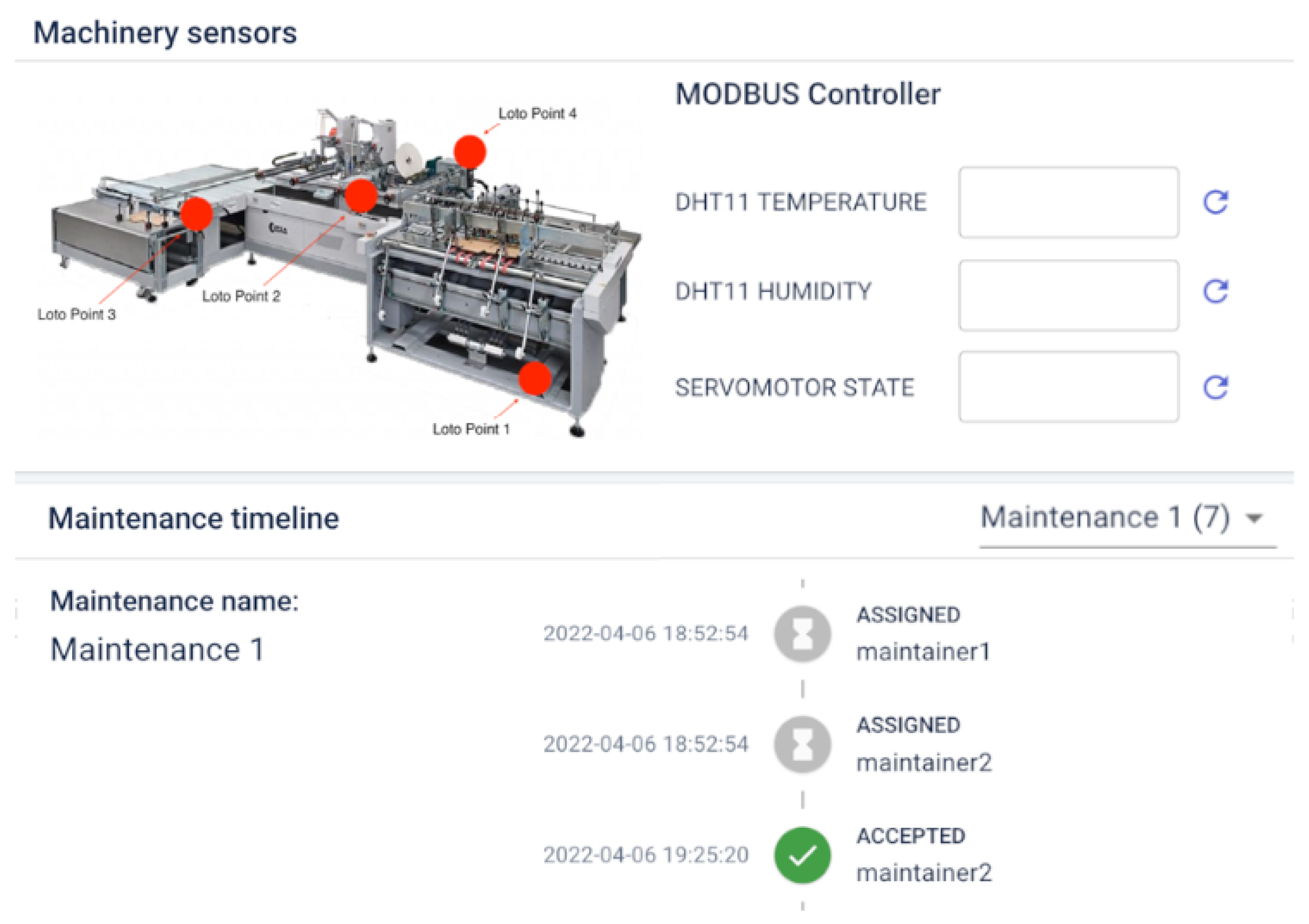
Figure 4 reports a screenshot of the dashboard, one of the most important components of the MwISM that provides support to supervisors and administrators in the execution of their duties during the de-energizing and re-energinzing operations.
Another important element of the system is the Backend Server component. For the purpose of this paper, it was realized by using different programming languages and tools: (a) the Java programming language and, specifically, the Spring Boot framework [
38], was used for the development of the whole Backend infrastructure, (b) the MySQL Database Service was used to implement the database for collecting all the data arriving from the machineries, (c) the WebSocket and MQTT protocols used for all the communications among the Backend and the other components of the architecture, (d) the Docker ecosystem used to simply the deployment tasks, (e) the ReactJS framework used for exposing the dashboards and (f) the Nginx reverse proxy used to support all the communications with specific services (e.g., first security barrier).
Finally, the last important component of the architecture that was implemented is the Mobile App. As already mentioned, it is a really important part of the system mainly because of its important role in guiding the operator through all the steps foreseen in the maintenance procedures.
In fact, while, usually, the maintenance procedures are reported in printed manuals or books, in our system, all the procedures and their steps are inserted in the database by the administrators, through the Dashboard provided by the Backend Server and, when an operator has to start a maintenance, he/she has only to open the mobile application, accept the assigned maintenance and then, all the steps are shown, after the verification of all the defined pre-requirements (e.g., the machinery is on maintenance with all the safety system working properly) on the screen step by step. Therefore, the Mobile App was realized for smartphones equipped with the Android Operating System (so, by using the Java Programming language) and it is responsible for all the operations reported in the previous section. In addition, the Mobile App provides a controlled sub-system that safely cooperates with the other system components, to allow maintainers to execute a limited set of interactions with the machinery (e.g., axes movements) to test the effective outcome of the maintenance operations without waiting for the intervention of a dedicated team with the right expertise to operate on the machinery itself (as done since now in the state of the art.
7. Tests and Results
The implemented ecosystem was used to experimentally verify the fulfillment of all the defined requirements and, consequently, verify the complete feasibility of the described functionalities. In fact, the implemented prototypes have been exploited to test the proposed ecosystem in a real pilot and specifically in an industrial plant based in central Italy.
Table 1 reports the definition of a realistic procedure that the operator have to accomplish during daily activities and shows the different components of the system involved in each step. It has been used as a guiding storyboard for the tests performed in the mentioned industrial plant. Each row of the table, corresponding to a step, reports the reaction performed by the system and the consequent improvement brought by our platform to the State of The Art (SoTA). Specifically, the second column named “Taken Action” describes each action performed by the various stakeholders of the system and represents the main guideline to be exploited by the reader to then investigate the components of the system involved in each step (reported in the first column), the processes that act in the background during each step (reported in the third column) and the main advances brought by our system in each step (reported in the forth column). Finally, the next section will present the feedback received by the plant security manager who were interviewed at the end of the tests to understand the real outcome of our system.
As a summary of the information reported in the table, it is possible to depict that almost all the components of the system are involved in each step to guarantee the safety of the operator and the fulfillment of all the required actions. In addition, the explicit details of a real procedure reveal the main advantages of which operators can benefit from a real-time guide and a chat throughout the whole process. Furthermore, the forth column highlights the main advances that our proposal can bring as an innovative contribution to the State of The Art about safety of machinery/workers.
During the tests of the second prototype, we exploited a real lathe machinery as “Machinery with Increased Safety Measures” and we simulated the maintenance (lubrication) of the machine axes. The Backend server was run on a machine with the following characteristics: CPU: Intel Core i3-3220 3.30 GHz; RAM: 8 GiB; Local Network Bandwidth: 1 Gigabit per second (Gbps). While, the Mobile App was run on a Android smartphone equipped with the “Qualcomm Kryo 470, octa-core CPU 2.3 GHz” GPU and 6 GiB of RAM. The system was deployed in a Local Area Network (LAN) that was completely closed to external interactions (with or through the Internet). The results of the tests are discussed in the following section.
8. Discussion
The described prototype has been deployed and tested in a real industrial plant based in central Italy. During the tests, an operator was asked to reproduce the maintenance procedure described in the previous Section, and, at the end of all the tests, the safety manager of the plant, who was supervising the procedure, was interviewed to identify the real benefits that our system can bring in a real industrial environment.
Therefore, based on the feedback received by the safety manager, the present section discusses all the advantages that the proposed solution can provide to the community by analyzing the fulfillment of all the requirements reported in
Section 5.
As declared by the safety manager, if an operator lubricates the axes of a machinery by exploiting our system (as done in the tests) it is possible to guarantee the respect of the following safety measures:
drastically reduce the reasonably foreseeable misuse of machinery as disciplined by ISO12100—Definition 3.24. Specifically:
- –
Usually, people never correctly apply LOTO procedures (e.g., locks are not used, compressed air is not removed, or sometimes the presence of unauthorized operators outside the control of maintenance service operators to speed up the service is exploited). Our system allows real-time monitoring of its correct application so, for instance, if an operator tries to turn the compressed air on when it has to be off, the system enters the “emergency status”, stops anything until an intervention is performed, the Smart Service mode is automatically disabled and the communication between the smartphone and the machine is closed.
- –
By only providing written instruction manuals, the available machinery and related systems operate and guarantee only the respect of the so-called “step 3” of the ISO12100 standard. Instead, with our system we can guarantee the fulfillment of the so-called “step 2” of the standard with “additional safety measures”. Moreover, we can guarantee the presence of only the assigned operator/s at the assigned position/s during maintenance.
allow maintenance also when the operator is not aware of the procedure or with a little knowledge of the control station of the machine;
drastically reduce the stops of the machinery and the specific training. Currently, when a machinery is under maintenance it is stopped for a time that is longer than the one needed for real maintenance mainly because someone has to verify that everything was correctly performed and that the procedure completely ended before starting the machinery again. In a huge industrial plant, it can cause long stops with a consequent reduction in earnings. With our system, it is possible to verify the proper end of all the steps of a procedure in real-time and, therefore, reduce the stops of the machinery and their duration to immediately start it again.
Simplify the procedures to verify the success of the performed maintenance actions. Currently, for their verification, it is necessary to ask trained staff to intervene and, for instance, try to move the maintained axes after the maintenance. Therefore, the possibility offered by our system to support, through the mobile app, the safe performing of maintenance actions (e.g., move axes) can be appreciated as a big advance in maintaining large industrial plants where the availability of specifically trained staff for each machine is very difficult.
The mentioned feedback received by the safety manager has been exploited to verify the correct satisfaction of all the defined requirements. Consequently,
Table 2 summarizes the main benefits brought by the adoption of our solution and compares them with the advantages brought by the analyzed related works. The “✓” represents a satisfied requirement, the “X” signifies an unsatisfied requirement, a “✓/X” refers to a semi-satisfied requirement and the “-” is used when the information is Not Available.
As depicted in the table and already summarized in
Section 4, to the best of our knowledge no work addresses all the defined requirements and completely serves the industry through a comprehensive solution able to guarantee the safety of operators working in maintenance operations. The main reason resides in the objectives pursued by the different analyzed solutions. In fact, usually, the works aim only at a single aspect or action performed during the maintenance actions and, in such a way, they are not able to guarantee the safety at the level required by different regulatory legislations and related standards. For instance, all the works operating in the Augmented and Virtual Reality cannot verify that the operator actually performed the suggested action and/or that he is in a safe zone while operating. Furthermore, the works that, instead, provide solutions to monitor both the operator and the machinery, usually face the problem by proposing summarizing solutions that do not care the aspects related to specific actions to be performed during maintenance (e.g., the necessity of turning the machinery off and, therefore, verifying the accomplishment of an action without interactions with the machinery) or do not support the operators through a dedicated chat that could be really useful when, for instance, the execution of the instructions do not cause the expected result or when the system is not properly working in the expected way.
As an additional relevant discussion, it is important to mention how our system guarantees the satisfaction of the Non-Functional Requirements mentioned in the dedicated
Section 4 and, therefore, how the performed tests demonstrated their fulfilment. As already mentioned, the developed prototype was deployed in a real industrial plant and was tested on a real machinery throughout a simulated realistic maintenance procedure.
Specifically, as already mentioned, we exploited a real lathe machinery and, during tests, we tested the maintenance (lubrication) of the machine axes. The local nature of the implemented prototype (it was deployed in a LAN without any access to and from the Internet) completely satisfies the security Non-Functional requirements and controls, together with the exploitation of the HTTPS protocol for every communication, all the possible security issues to which the system can be exposed. In addition, the requirement related to Usability has been verified through the mentioned interview of the Safety manager. The fulfilment of all the other Non-Functional requirements, instead, is based on the “Eurostat” statistics [
41] that declares on one hand that 67% of European employees work in small-medium companies and, on the other hand, that in such small-medium companies there are no more than five people that simultaneously maintain no more than two machineries in one/two working days per machinery. As a consequence of such a declaration, our system is completely able to serve most of the real situations that can occur in a real European Industrial plant. Indeed, the performed tests that demonstrated a prompt reaction of the system to requests and interactions (the highest delay in response was 0.5 s) is completely in line with the requirements related to Performance, Reliability, Availability, Maintainability and Scalability.
In conclusion, our solution provides a useful support for all the companies that usually have to train a new maintenance team with respect to the specific machineries present in their plants. In fact, through our system, the company will not need a full training course because all the procedures can be defined within the system and the steps are shown step by step to the operators only when they are needed and only if all the safety requirements are satisfied (e.g., machinery peripherical guards closed). Such advantages will result in lower costs for the maintenance, lower time for the training of operators and, also, lower accidents in industrial plants. In addition, the implementation of the two different prototypes of the Machinery with Increased Safety Measures gave us the possibility to compare the typical research conducted in research institutes (e.g., universities) with the more concrete industrial approach. The innovative developed control system adds real and concrete safety measures that can save the life of operators with less than 5% of additional costs, as verified when the safety measures were implemented on the the second real prototype of the MwISM. The functional validation discussed in the last two sections demonstrates the compliance of the system with the requirements reported in
Section 4 and validates the architecture on the field by revealing key system bottlenecks during a fully simulation of a common system usage. In fact, the performed functional validation provided a proof of the validity of the proposed solution and demonstrated the innovative contribution that our system can bring in the industrial domain in improving the safety of operators during the maintenance processes.
9. Conclusions
Within the present paper, we proposed an IoT architecture for the industrial domain to support maintenance operators. It is designed to guide operators step by step during the maintenance procedures while real-time monitoring the plant, the machinery and the other employees working in the same area. Different modules are integrated in the architecture and exploited during the maintenance to monitor the status of the different parts of the plants, the machineries, and the operators themselves to, then, authorize and show the next steps foreseen in the procedure defined by the administrators or the supervisors. Furthermore, during the maintenance, the operators are allowed to communicate and exchange messages with the administrators to, for instance, ask clarifications about a procedure. Finally, warning notifications are sent to the operators when a dangerous situation is foreseen by the system and/or by the supervisors.
To test the feasibility and effectiveness of the proposed infrastructure, a prototype was implemented and functionally tested through the exploitation of a machinery simulator and a real lathe machine.
The functional validation provided a proof of the validity of the proposed solution and demonstrated the innovative contribution that our system can bring in the industrial domain with the aim of improving the safety of operators during the maintenance processes.
The proposed system is a starting point for the researchers and practitioners interested in guaranteeing workers’ safety in the industrial maintenance process through the exploitation of IoT solutions. In fact, it can foster the enhancement of existing works by introducing verification procedures and minimum requirements to be satisfied to operate in the maintenance domain. Furthermore, it can lead the way to innovative future works that would like to monitor operators in every condition, also the one that supervisors cannot monitor (e.g., due to the absence of full visibility of workers). Moreover, it can also help administrators to demonstrate that a “qualitative” reduction of risk is possible and effective on workers mood. As a further future work, our system could promote the adoption of techniques to let administrators interact with machineries without being physically present near them (for instance by a security officer) to be sure that all the procedures foreseen by different machineries builders are respected.


 ,
, 


