
Optimal Lyapunov-Based Sliding Mode Control for Slotless-Self Bearing Motor System

1
School of Electrical & Electronic Engineering, Hanoi University of Science and Technology, Hai Ba Trung, Hanoi 100000, Vietnam
2
Institute for Control Engineering and Automation, Hanoi University of Science and Technology, Hai Ba Trung, Hanoi 100000, Vietnam
*
Author to whom correspondence should be addressed.
Appl. Syst. Innov. 2023, 6(1), 2; https://doi.org/10.3390/asi6010002
Submission received: 29 November 2022
/
Revised: 14 December 2022
/
Accepted: 16 December 2022
/
Published: 22 December 2022
(This article belongs to the Section Control and Systems Engineering)
Abstract
:A slotless self-bearing motor (SSBM) is a new type of electric motor, with its levitating and rotating capability as a drive system. In the design of motor, the iron core of stator was removed, it could have many advantages such as small size, light, no friction loss, low losses, high speed. Besides, disturbance and uncertainty factors are the unexpected values, which impacting strongly to the output of the control system. In this paper, to reject the effects of these factors, an optimal Lyapunov-based (OLB) sliding mode control (SMC) was proposed to control the movements and rotation of SSBM system. First, the mathematical model with uncertainty and disturbance factors of the SSBM system was rewritten to show the detail configuration of the proposed motor. Second, the OLB-SMC controllers were designed for the control of displacements on -, y-axes, rotor speed on -axes, respectively. Third, the stability analysis of control algorithm was demonstrated via the Lyapunov stability theory. Finally, the experimental test was implemented to prove the high performance of the OLB-SMC for SSBM system. The practical results show that the effectiveness of OLB-SMC controller for SSBM system. The novelty of the proposed method is that the stability condition was newly proposed based on the transformation from scalar equation to state-space equation, where the gains of controller were found based on the linear matrix inequality.
1. Introduction
Disturbance and uncertainty are two main factors affecting to the control output of the system. These factors are mainly souced by the outside effect and inside variations. The disturbance of the slotless self-bearing motor (SSBM) comes from the self vibration due to the reason of the length of the rotor. To reduce the vibration, the controller need to be a robustness controller or the disturbance observer need to be equipped. Furthermore, the uncertainties comes form the incorrect winding, incorrect fabrication, and so on are also the inversed problem of not only SSBM. To achieve the expected values, a powerful controller is required to refuse these inversed factors. In particular, the external perturbations affect on the rotor of SSBM and its self-vibration. A sliding mode control (SMC) will be proposed in this paper to decrease the unknown parameters for SSBM. First, the general concepts of the proposed motor can be found in [1,2,3,4,5,6]. The disturbance and uncertainty are considered as unknown and unexpected values, and the discussion of these values was presented in [6]. Herein, the mathematics of SSBM are expressed for reader easy to understand the ideas of the work. Generally, the disturbance parameter is the outside factors such as wind blowing, etc, and the uncertainty parameter is the inside factors such as thermal change of the system in the working operation. Besides, the fabrication errors are also considered as hard factors, that strongly affect to the precision of the control system. Moreover, the fabrication errors will lead to the winding error. In detail, the reason of the perturbations factors of the SSBM motor was shown in the [7]. Herein, an optimal control algorithm for the SSBM is required. The basic concepts of modeling and control for the bearingless motor was discussed in the paper [8]. The analysis and control of the bearing system was presented in [9,10]. Furthermore, an adaptive placement control for commissioning of a active magnetic bearing system (AMBs) was disscussed in the [11], the disturbance observer-based control methods for the AMBs can be found in [12,13,14]. Moreover, the advanced control methods for the bearingless system can be found in [15,16]. In additional, the sensorless speed control of bearingless motor was proposed in the paper [17,18,19,20], the design and analysis of hardware was presented in [21,22] and the force analysis of SSBM in paper [23]. To reject the perturbations of SSBM was discussed in the previous paper [7]. In this paper, an optimal control will be proposed for SSBM system.
In recent years, the magnetic bearing motor has been interesting topic. The configure of the magnetic bearing actuator was discussed in the paper [24,25,26] but it is large. To reduce the size of the system, the reduction size of the magnetic bearing systems was discussed in [5,8,10]. The proposed SSBM was presented with its levitating and rotation capability. To control the SSBM, the movements and rotation must be controlled. In this paper, an OLB-SMC method will be proposed to complete the expected target.
SMC method is a class of robust control method, which gives robust power for a drive system with uncertainty and disturbance factors. SMC is also a nonlinear control technique, which can be used to control a linear or nonlinear object. The detail idea and theory of SMC method can be found in paper [27]. SMC method consists of an equivalent and a switching values. Featuring the switching control constant comes up with the chattering problem, the elimination of the switching function can be found in [28]. In the paper [29,30], a robust SMC method was presented. A robust SMC for SSBM system was investigated in previous paper [7]. The Lyapunov stability analysis can be found in [31,32]. In recent years, the new stability for SMC and disturbance observer are investigated such as [33,34,35]. The provided stabilities in these papers are aimed to force the state and disturbance to the predefined value in the fast time and fixed-time, respectively. In this paper, an OLB-SMC method was proposed for SSBM system with the verification of the practical study. The novelty of this paper is that a new stability condition was intelligently proposed based on pole placement method. The aim of the propsosed method is that to softening the calculation of stability analysis. The proposed stability condition can be expanded for many stability condition of disturbance and state observers.
Motivations of the work are came from the works of [3,4,9], the perturbations factors were ignored. Second, in the paper [9] proposed the PID controller without considering the disturbance and uncertainty effects. Third, to reject the unexpected factors so a new disturbance rejection technique was discussed in [6], but it just verified via the simulation. Therefore, this paper applied an optimal SMC method to increase the power of system. The performance of the proposed control method was completed by the practice system and was compared with our previous paper [9]. Otherwise, the main effort of this work is to provide the new Finally, the prime contributions of this work are listed by
1. The mathematical model of SSBM was slightly rewritten with considerations of perturbations. These unexpected factors were rejected by the optimal control algorithm, which were evaluated by experimental test.
2. The OLB-SMC method was discussed for the control of movements rotation of SSBM motor with the consideration of the uncertain and disturbance effects.
3. The stability of the proposed theory was analyzed by using the Lyapunov condition and experimentally validated via the practical system.
4. This research was completed by the support of the dSPACE DS1104 controller board with the linking of MATLAB software. The originality of the paper is that the proposed stability is newly proposed via the Lyapunov based with the poles placement method for softening the provement of stability analysis.
The paper is constructed by. Second, the mathematical model with the consideration of disturbance and uncertain for the SSBM is slightly represented. Third, the design of the OLB-SMC was given, and the stability was proved via the Lyapunov theory. Finally, the practice tests will be performed to prove the performance of the OLB-SMC controller.
2. Mathematical Model of the SSBM
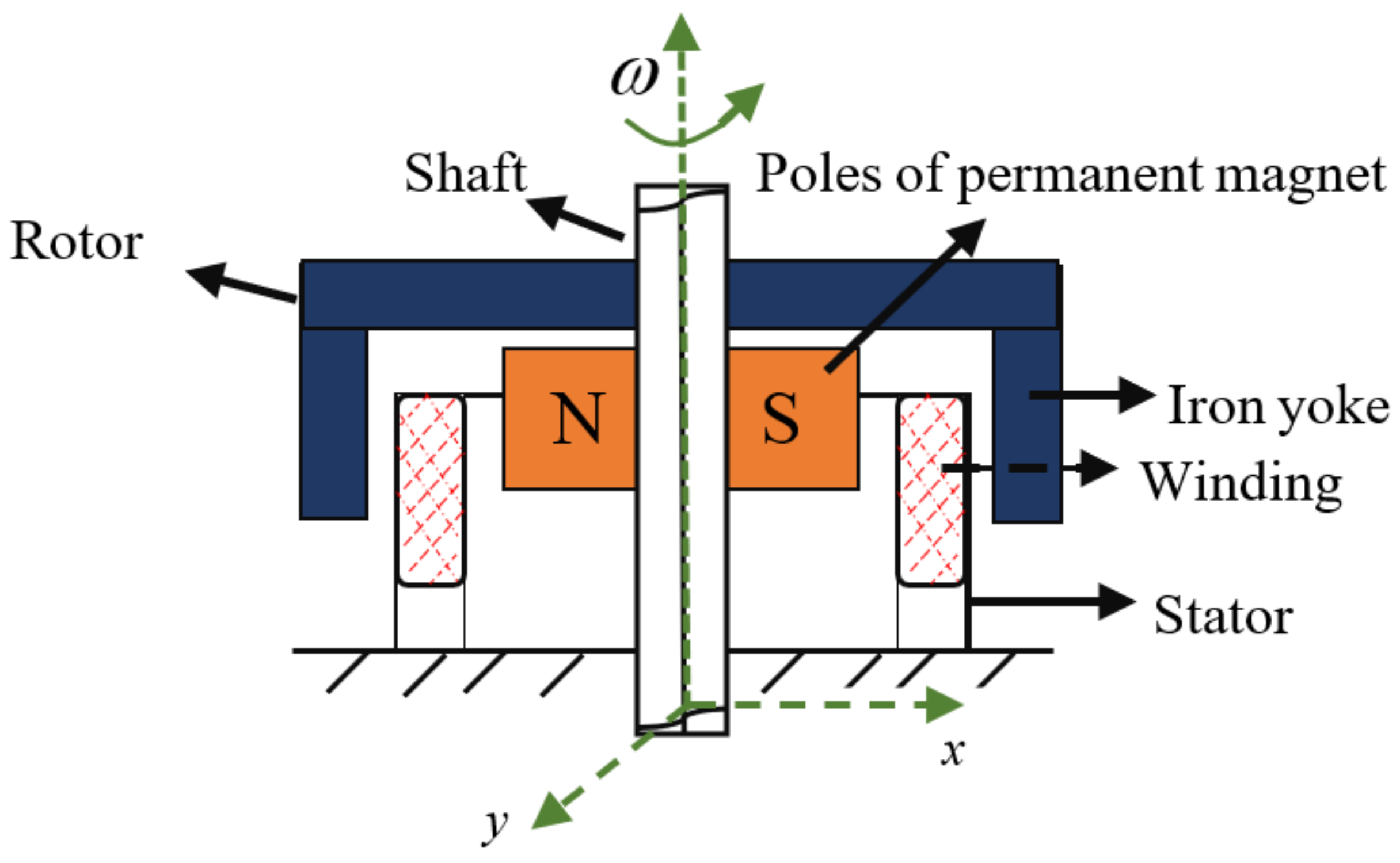
Structurally, the SSBM is considered as 2 main parts: the stationary and the moveable parts. In detail, the configuration and mathematical model of the SSBM was presented in [6,9]. Which is shown in the Figure 1 below.
The stator coils are designed according to the hexagonal shape. The six-phases are arranged around the coordinate plane, a-b-c phases symmetry with d-e-f phases, respectively. The phase winding errors, it can affect to the control output, strongly.
The bearing forces of the symmetrical phase a-b-c is as follows:
where , , and are the fabrication error of each phases, l is the length of the wire, , , and are the phase bearing currents, respectively.
To the balance of the rotor, the total amplitude of the Lorentz force needs to be zero. So, the balance equation Equation (1) is
From Equations (1) and (2) leads to
Therefore,
Remark 1.
In fact, the right hand side of Equation (4) is not zero. It can be considered as a perturbation value. With , and is the phase bearing currents, respectively.
The torque and bearing forces with considering the disturbance and uncertainty are expressed as follows:
The structure of the SSBM was shown as in Figure 1, the torque and forces were not affected by the gravity. We have
where , and are the rotating torque on -axis and bearing forces on x- and y-axis, respectively. , and are the disturbances on the on x-axis, y-axes and -axis, respectively. Combining the Equations (5) and (6),
The the perturbations also need to be bounded.
3. Proposed Approach
This section presents the OLB-SMC for the displacements and rotation for the SSBM on x-, y- and -axes, respectively. First, the OLB-SMC for -axis is presented as follows:
3.1. The OLB-SMC for ω-Axis
The proportional–integral surface is selected for the speed control, the surface equation is given as follows:
where . When the system state is converged to the predefined surface, the must be positively defined, which helps the state-space error go to the zero in finite time. The derivative equation of Equation (8) is,
Considering and disturbance is zero, the Equation (9) can be expressed as follows:
Combining the Equations (7) and (9) yields,
So, the equivalent term is calculated as follows:
and the switching control term is
Second, the OLB-SMC for x-axis is presented below.
3.2. The OLB-SMC for the x-Axis
Select the proportional–derivative surface of SMC for the x-axis, the surface equation is given as follows:
where . When the system state is converged to the predefined surface, the must be positively defined, which helps the state-space error go to the zero in finite time if the tracking error is different zero. The derivative of Equation (14) is
when considering and disturbance is zero, Equation (15) can be expressed as follows:
Combining the Equations (7) and (16) yields
So, the equivalent term is calculated as follows:
and the switching control term is selected as blow:
Third, the OLB-SMC for y-axis is below.
3.3. The OLB-SMC for the y-Axis
Select the proportional–derivative surface of SMC for the y-axis, the surface equation is given as follows:
where . Similarly, the surface of SMC for y-axis should be selected as similar with the surface of controller for x-axis. The derivative of Equation (20) is
when considering and disturbance is zero, Equation (21) is rewritten as follows:
Combining the Equations (7) and (22) yieldsm
So, the equivalent term is calculated as follows:
and the switching control term is selected as blow:
Remark 2.
The switching control gains values , , , , and should be a positively defined.
Finally, the stability was proved as the Lyapunov Stability theory.
3.4. Stability Analysis
First, the Lyapunov candidate is
The time derivative of Equation (26) yields
Using Equations (11)–(13), (17)–(19), and (23)–(25) to solve Equation (27) yields
or
or
For softening the calculations and proof of the stability of whole system the Equation (30) should be transferred to the equation such as follows:
The system is stable when the eigenvalues of the matrix is optimally located in the left side of the plane.
The performance of the OLB-SMC for SSMB system is given as the following section.
4. An Illustrative Example
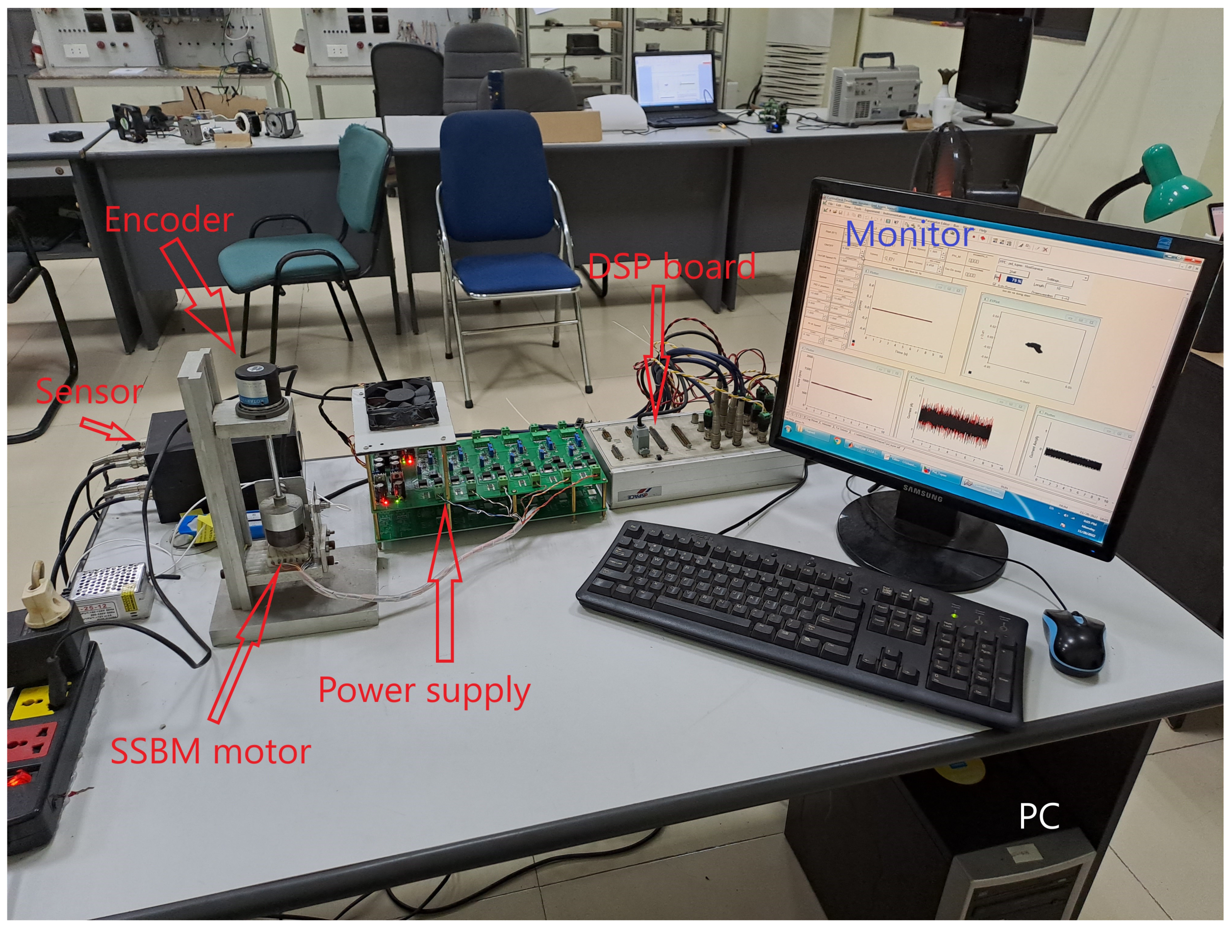
To shown effectiveness of the OLB-SMC, the experimental verifications was implemented in two condition operation. The detail parameters of the SSBM system are referred to the previous paper [8]. The fully hardware setup in practice is displayed in the Figure 2.
The experimental system is listed as follows: a PC computer system supported by the Windows XP, a dSPACE DS1104 controller board, two displacement sensors, a six-phases power amplifier system, the SSBM motor and a rotary encoder.
The sampling frequency is 10 kHz. The configuration of the control system will be shown in the Figure 3 below.
The block is used to present that the initial position of SSBM is . The initial angular position of the SSBM is , the detail analysis of the block was discussed in reference paper [8]. From Equation (5), the torque can be controlled by and the bearing force can be controlled by , . These values are calculated after the block controller OLB-SMC. The block , that is used to transform the amplitude to the phases torque current, is known as the current transfer block. The phases bearing current is obtained after transferring id, iq via the block. Then, the total current of each phase is obtained. These reference currents is sent to the amplifier system via the DAC channels of the dSPACE 1104 controller board. Then, the phases stator current was supplied through the power amplifier. In this research, the SSBM system was considered operating in the two conditions: free and sudden load. The movements were measured by the displacement sensors. The speed was measured by the rotary encoder. These sensors convert the measured values to voltages. And then, the ADC channels of dSPACE board read the values.
The control parameters are listed as follows: , , , , , , , , . The experimental test was completed with two cases study, the results are shown as follows:
- Case 1: (rpm)
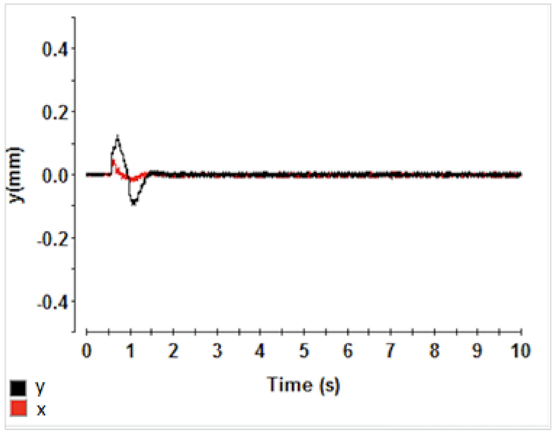
In this case, the motor speed was 1000 (rpm) with free-load. The experimental results are displayed as follows: in Figure 4: The displacements on x-axes and y-axes, in Figure 5: the rotor speed, in Figure 6: the rotor orbit, in Figure 7: the bearing current and , and in Figure 8: the torque current .
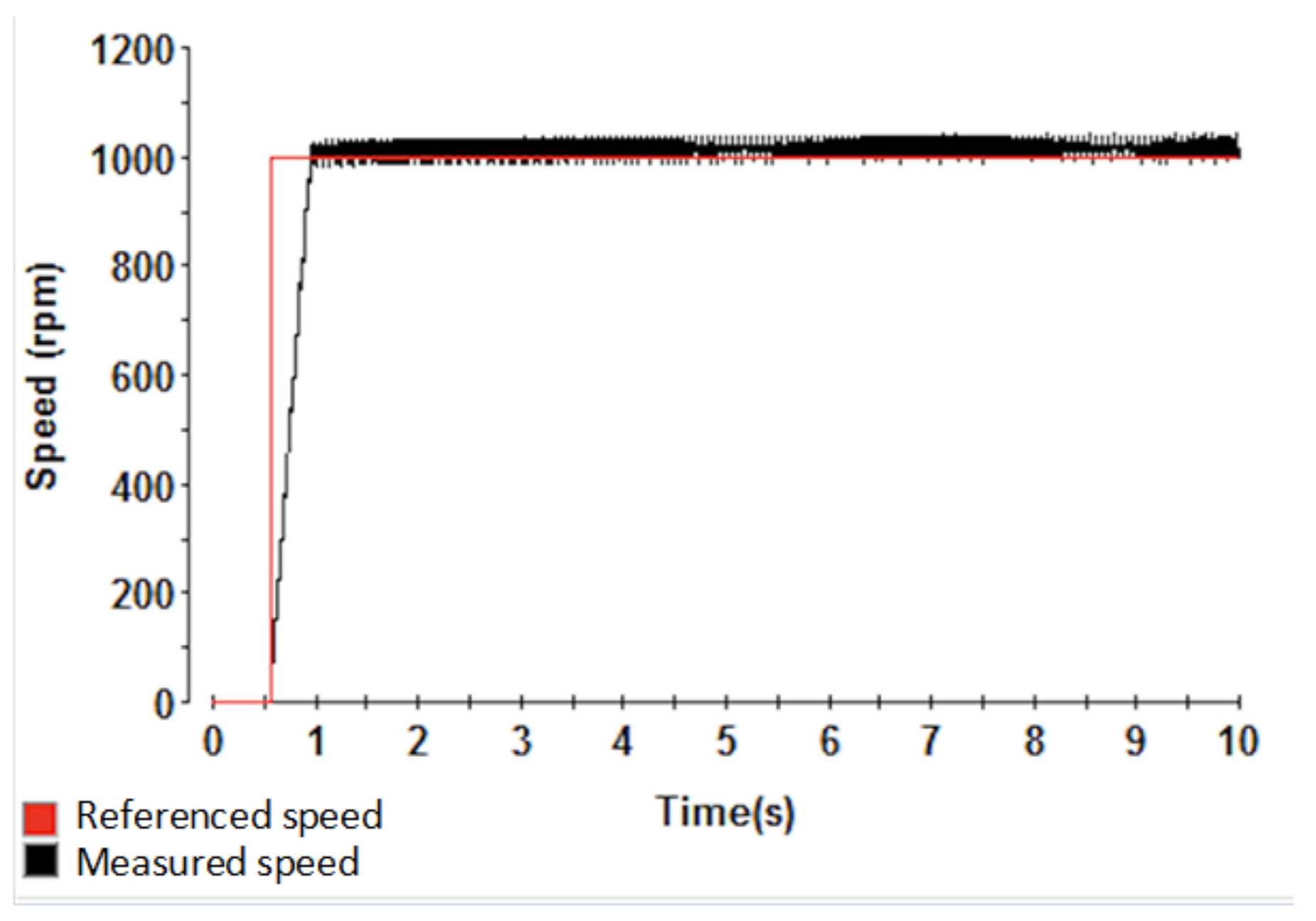
In the Figure 4, the overshoots on x-, and y-axes are (mm) and (mm), the response time is 1 s. The rotor speed shows in the Figure 5 below.
Figure 5.
The rotor speed.

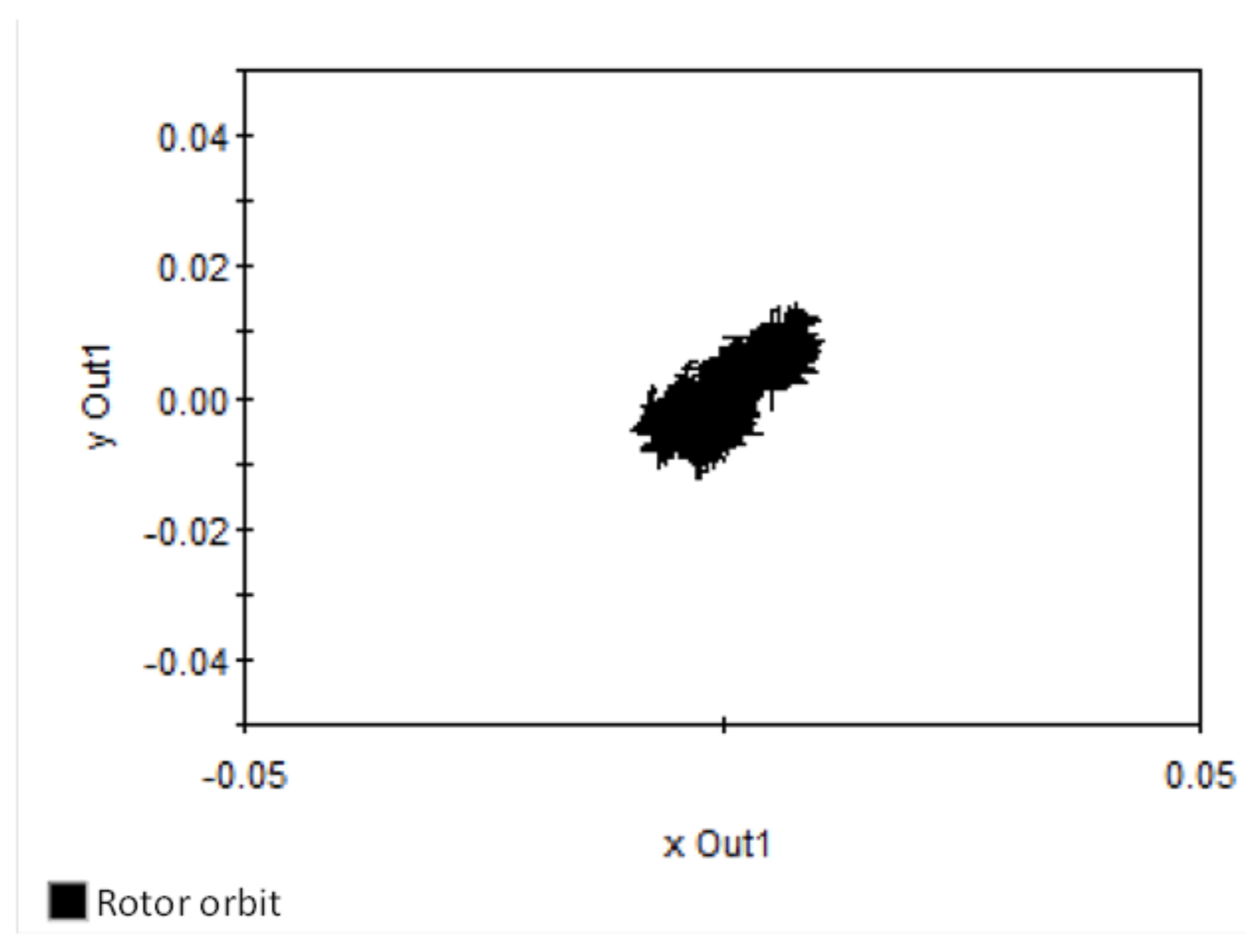
The motor speed can reach 1000 (rpm) in s. In the Figure 6, the rotor orbit is displayed.
Figure 6.
The rotor orbit.

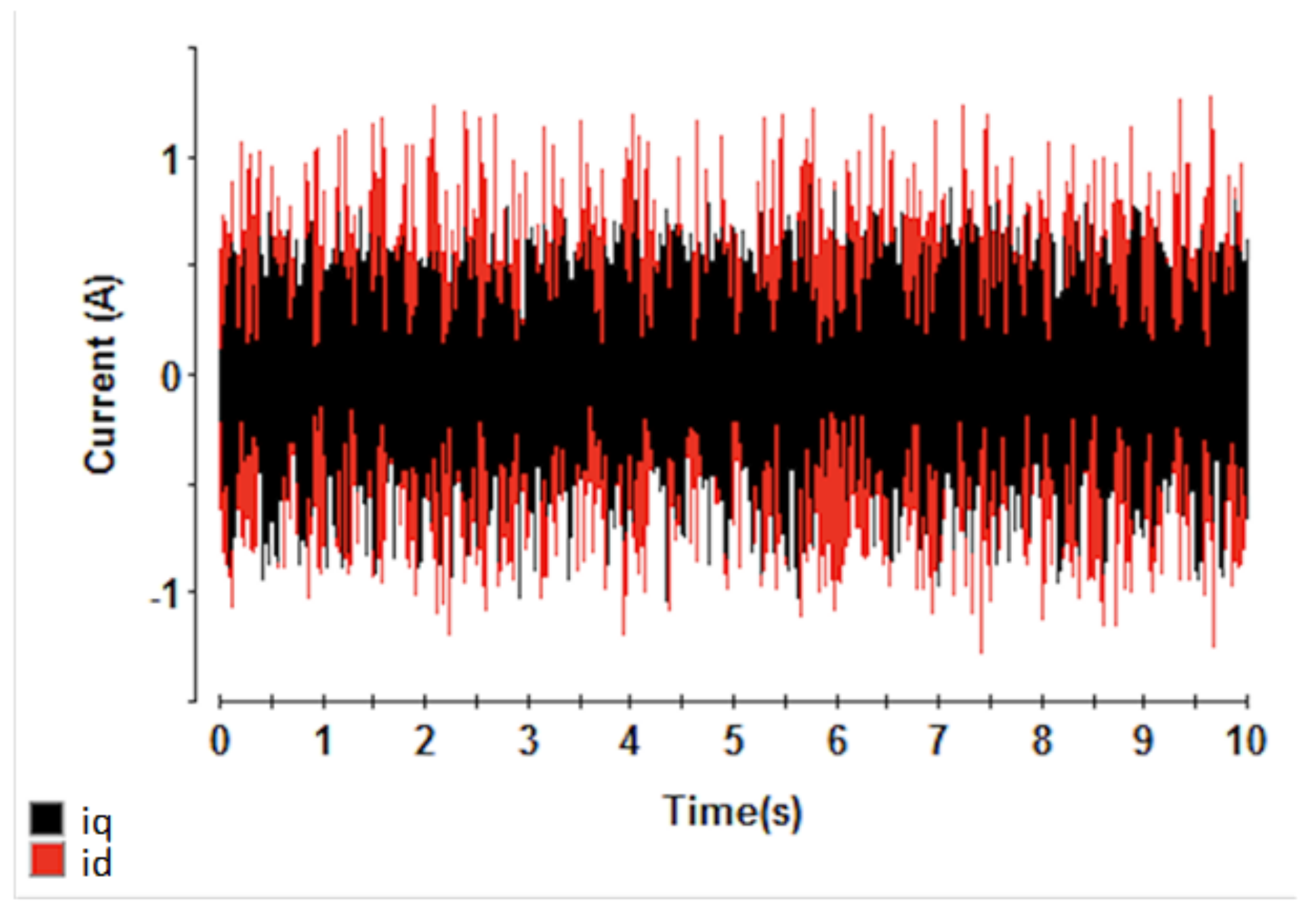
The rotor of SSBM motor is moved around the stable point. The bearing currents are shown in the Figure 7.
Figure 7.
The bearing currents .

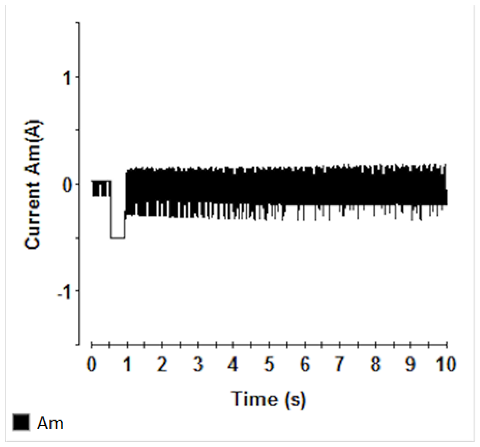
The range of the bearing currents is −1 (A) 1 (A). The torque current is shown in the Figure 8.
Figure 8.
The torque current .

The peak of torque current is −0.5 (A), and the range of is −0.7 0.3 (A). The first step to test the system is as follows: the SSBM system is in the steady-state working operation at the initial speed is 0 (rpm). At 0.5 (s), the referenced speed is increased from 0 (rpm) to 1000 (rpm). The overshoots of the displacements are (mm), and (mm). The respond time of the displacements is 1 (s). The rotor speed can catch the referenced speed in 0.5 (s). In the steady-state operation, the displacements errors are small, the range of error is (mm), and (mm). The rotor orbit is converged to the original point. The range of torque current is −0.7 0.3 (A), when the motor is accelerating, the peak of is −0.5 (A). The range of bearing current is −1 1. To verify the performance of the controller, the referenced speed was 1500 (rpm) with sudden load.
- Case 2: (rpm)
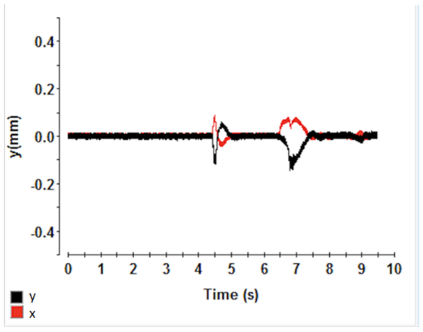
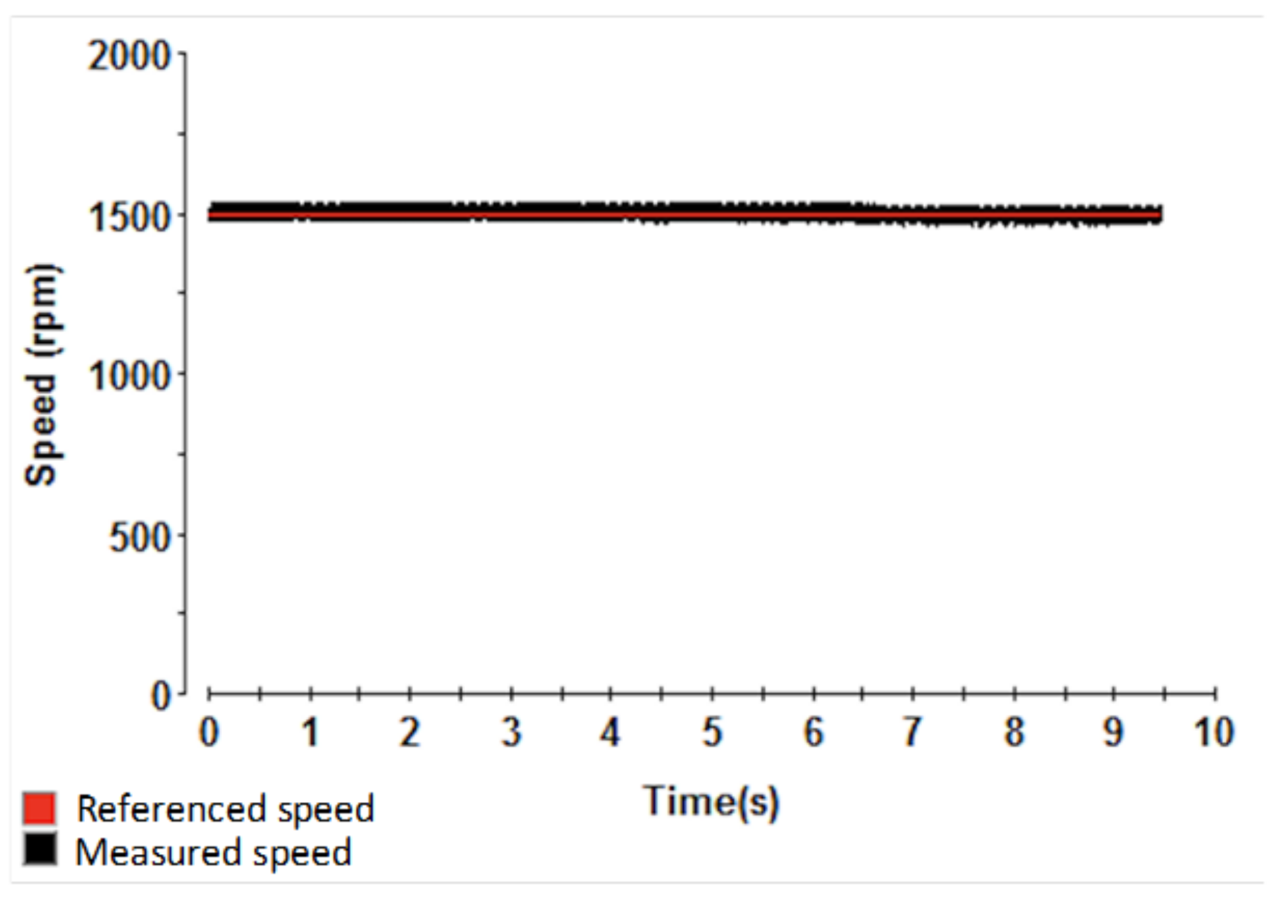
In this case, the motor speed was 1500 (rpm) with sudden load. The experimental results are given as below. The displacements on x- and y-axis is shown in the Figure 9.
The overshoots of x, and y are (mm), and (mm) when there is a sudden load impacting to the rotor of SSBM motor. When the load is disappeared, the overshoots of x and y are (mm), and (mm). After, there is a small load impacting to the SSBM system, the displacements are small. In the Figure 10, the rotor speed is shown.
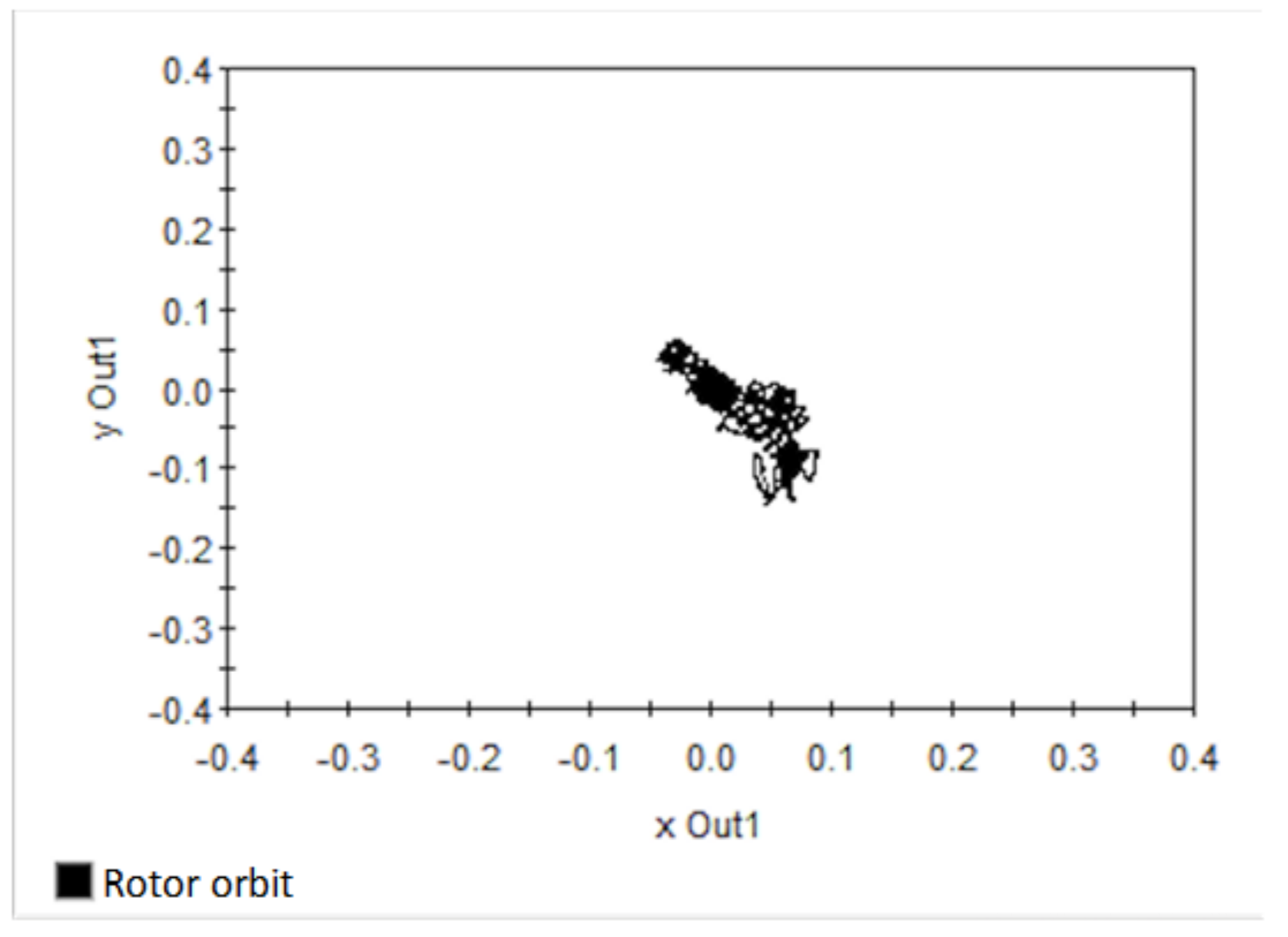
The SSBM system is stable at 1500 (rpm). The rotor orbit is shown in the Figure 11.
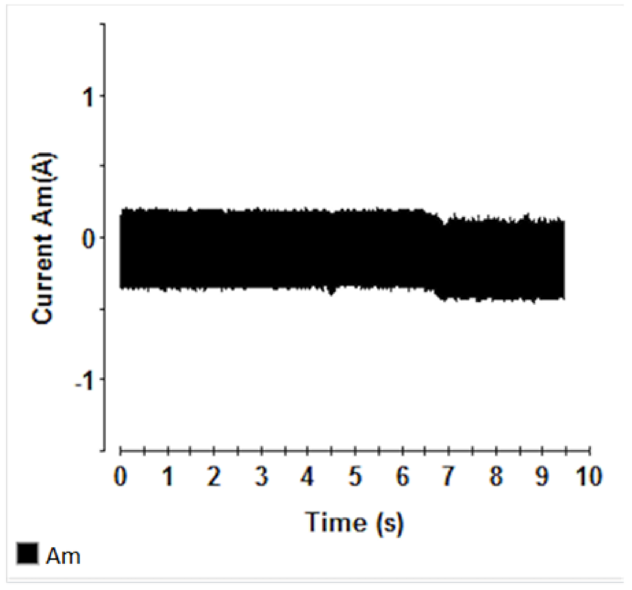
When the sudden load is given and to the rotor and removed from the rotor, the rotor orbit is left the zero point and after that it is come back to the original point. In the Figure 12, the bearing currents is expressed.
The range of the bearing currents in this case is −1 (A) 1 (A). The torque current is shown in the Figure 13.
The range of the torque current is (A), it is not significantly changed since the rotation is generated by but the rotor shaft is got the sudden load on x- and y-axes.
The SSBM system is in the stable operation at the 1500 (rpm). The power of this controller with sudden load was confirmed at observing the change of x-axes and y-axes. When motor is in the steady-state working operation. The range of the displacement error is 0.03 (mm). From 4.5 (s) to 5 (s), impacting a sudden load to the rotor axis, the changes of x-axes and y-axes are (mm). After that, the displacement was following the stable point. At time 6.5 (s), the sudden force is disappeared, the signal on x- and y-axis leave the stable point but it quickly reaches the stable state. Finally, the force load is 0.3 (N), impacting to the rotor shaft in a short time, the displacements is small. The range of bearing current is −1 1, and the torque current is −0.4 0.3. The speed of the SSBM motor is stable at the 1500 (rpm) during this practice test.
This experimental results are compared with the paper [9]. In the previous paper, the SSBM system is assumed to be the ideal system, the perturbations are ignored to make the system simplest and the displacement errors are bigger than this result of research. Moreover, the SSBM system was not tested with sudden load condition. The proposed OLB-SMC was good in the control of the movements and rotation.
5. Conclusions
In this study, the mathematical modeling of SSBM motor with the consideration of the disturbance and uncertainty effects was represented. The newly prosed method of OLB-SMC was provided with fully analysis of theory and experiment for the control of the displacements and rotation of the SSBM system, and it was expected to reject the disturbance and uncertainty factors. The stability of the system was proved the exactness of the Lyapunov theory. The performance of the proposed OLB-SMC for SSBM system was verified in the experimental system. There are two cases were used to test the performance of the proposed theory. Both cases with load and no load are tested and also given the good results. However, in the load case, it takes a little bit time to movements on x- and y-axes. The obtained result shown that the proposed concept can be applied in real study for many other physical controlled system. Otherwise, the proposed theory can be used to construct the convergent condition of state and disturbance observers as well.
To disturbance observer for SSBM system can be discussed in the future work.
Author Contributions
Methodology, V.N.G.; formal analysis, M.H.T., writing—original draft preparation, M.H.T. and Q.D.P., supervision, V.N.G. All authors have read and agreed to the published version of the manuscript.
Funding
This research received no external funding.
Data Availability Statement
Not applicable.
Acknowledgments
This work was supported by the Ministry of Education and Training, Vietnam, under Contract CT2020.02.BKA.05.
Conflicts of Interest
The authors declare no conflict of interest.
References
- Steinert, D.; Nussbaumer, T.; Kolar, J.W. Slotless bearingless disk drive for high-speed and high-purity applications. IEEE Trans. Ind. Electron. 2014, 61, 5974–5986. [Google Scholar] [CrossRef]
- Steinert, D.; Nussbaumer, T.; Kolar, J.W. Evaluation of One- and Two-Pole-Pair Slotless Bearingless Motors with Toroidal Windings. IEEE Trans. Ind. Appl. 2016, 52, 172–180. [Google Scholar] [CrossRef]
- Ueno, S.; Kato, T. A Novel Design of a Lorentz-Force-Type Small Self Bearing Motor. In Proceedings of the 8th International Conference on Power Electronics and Drive Systems, Taipei, Taiwan, 2–5 November 2009; pp. 926–931. [Google Scholar]
- Ueno, S.; Uematsu, S.; Kato, T. Development of a Lorentz-Force-Type Slotless Self-Bearing Motor. J. Syst. Des. Dyn. 2009, 3, 462–470. [Google Scholar] [CrossRef] [Green Version]
- Ueno, S.; Iseki, R.; Jiang, C. Stability of a tilt-controlling axial gap self-bearing motor with single-stator. Mech. Eng. J. 2017, 4, 1–12. [Google Scholar] [CrossRef] [Green Version]
- Nguyen, Q.D.; Nguyen, H.P.; Vo, D.N.; Nguyen, X.B.; Ueno, S.; Huang, S.-C.; Giap, V.N. Robust Sliding Mode Control-Based a Novel Super-Twisting Disturbance Observer and Fixed-Time State Observer for Slotless-Self Bearing Motor System. IEEE Access 2022, 10, 23980–23994. [Google Scholar] [CrossRef]
- Nguyen, Q.; Nguyen, H.; Nguyen, K.; Vo, D.; Nguyen, X.; Ueno, S.; Giap, V. Robust Sliding Mode Control for Slotless-Self Bearing Motor System. J. Electr. Eng. Technol. 2022, 1–15. [Google Scholar] [CrossRef]
- Nguyen, Q.D.; Ueno, S. Modeling and control of salient-pole permanent magnet axial gap self-bearing motor. IEEE/ASME Trans. Mecha 2011, 16, 518–526. [Google Scholar] [CrossRef]
- Nguyen, H.P.; Nguyen, X.B.; Bui, T.T.; Ueno, S.; Nguyen, Q.D. Analysis and control of slotless self-bearing motor. Actuators 2019, 8, 57. [Google Scholar] [CrossRef] [Green Version]
- Nguyen, Q.D.; Ueno, S. Analysis and control of non-salient permanent magnet axial-gap self-bearing motor. IEEE Trans. Ind. Electron. 2011, 58, 2644–2652. [Google Scholar] [CrossRef]
- Nevaranta, N.; Jaatinen, P.; Vuojolainen, J.; Sillanpää, T.; Pyrhönen, O. Adaptive MIMO pole placement control for commissioning of a rotor system with active magnetic bearings. Mechatronics 2020, 65, 102313. [Google Scholar] [CrossRef]
- Giap, V.N.; Huang, S.-C. Effectiveness of fuzzy sliding mode control boundary layer based on uncertainty and disturbance compensator on suspension active magnetic bearing system. Meas. Control 2020, 53, 934–942. [Google Scholar] [CrossRef] [Green Version]
- Giap, V.N.; Huang, S.-C.; Nguyen, Q.D.; Trinh, X.T. Time varying disturbance observer based on sliding mode control for active magnetic bearing system. In Proceedings of the International Conference Material, Machines and Methods for Sustainable Development, Nha Trang, Vietnam, 12–14 November 2020; pp. 929–935. [Google Scholar]
- Giap, V.N.; Huang, S.-C. Generalized proportional integral disturbance observer-based fuzzy sliding mode control for active magnetic bearing system. In IOP Conference Series: Materials Science and Engineering; IOP Publishing: Bristol, UK, 2021; Volume 1113, p. 012006. [Google Scholar]
- Su, T.-J.; Kuo, W.-P.; Giap, V.-N.; Quan Vu, H.; Nguyen, Q.-D. Active Magnetic Bearing System Using PID-surface Sliding Mode Control. In Proceedings of the 2016 Third International Conference on Computing Measurement Control and Sensor Network (CMCSN), Matsue, Japan, 20–22 May 2016; pp. 5–8. [Google Scholar] [CrossRef]
- Tsai, T.S.H.; Su, T.J.; Cheng, J.-C.; Lin, Y.-Y.; Giap, V.-N.; Guo, S.M.; Shieh, L.S. Robust observer-based optimal linear quadratic tracker for five-degree-of freedom sampled-data active magnetic bearing system. Int. J. Syst. Sci. 2018, 49, 1273–1299. [Google Scholar] [CrossRef]
- Nguyen, Q.D.; Ueno, S. Sensorless speed control of inset type axial gap self-bearing motor using extended EMF. In Proceedings of the 2010 International Power Electronics Conference-ECCE ASIA -, Sapporo, Japan, 21–24 June 2010; pp. 2260–2264. [Google Scholar] [CrossRef]
- Nguyen, D.Q.; Ueno, S. Sensorless speed control of a permanent magnet type axial gap self-bearing motor. J. Syst. Des. Dyn. 2009, 3, 494–505. [Google Scholar] [CrossRef]
- Nguyen, Q.D.; Ueno, S. Improvement of sensorless speed control for nonsalient type axial gap self-bearing motor using sliding mode observer. In Proceedings of the 2010 IEEE International Conference on Industrial Technology, Vina del Mar, Chile, 14–17 March 2010; IEEE: Piscataway, NJ, USA, 2010; pp. 373–378. [Google Scholar]
- Nguyen, Q.D.; Ueno, S. Novel Approach in Sensorless Speed Control of Salient Axial-Gap Self-Bearing Motor Using Extended Electromotive Force. IEEJ Trans. Ind. Appl. 2011, 131, 1023–1028. [Google Scholar] [CrossRef]
- Borque Gallego, G.; Rossini, L.; Achtnich, T.; Araujo, D.M.; Perriard, Y. Efficiency Optimization of Slotless Magnetic-Bearing Machines. IEEE Trans. Ind. Appl. 2021, 57, 6833–6843. [Google Scholar] [CrossRef]
- Geng, W.; Zhang, Z. Investigation of a New Ironless-Stator Self-Bearing Axial Flux Permanent Magnet Motor. IEEE Trans. Magn. 2016, 52, 8105104. [Google Scholar] [CrossRef]
- Gallego, G.B.; Rossini, L.; Achtnich, T.; Zwyssig, C.; Araujo, D.M.; Perriard, Y. Force Analysis of a Slotless Lorentz-Type Active Magnetic Bearing Actuator. In Proceedings of the 2018 21st International Conference on Electrical Machines and Systems (ICEMS), Jeju, Republic of Korea, 7–10 October 2018; pp. 75–80. [Google Scholar] [CrossRef]
- Okada, Y.; Dejima, K.; Ohishi, T. Analysis and comparison of PM synchronous motor and induction motor type magnetic bearings. IEEE Trans. Ind. Appl. 1995, 31, 1047–1053. [Google Scholar] [CrossRef]
- Ren, Z.; Stephens, L.S. Closed-loop performance of a six degree-offreedom precision magnetic actuator. IEEE/ASME Trans. Mechatronics 2005, 10, 666–674. [Google Scholar] [CrossRef]
- Schneider, T.; Binder, A. Design and evaluation of a 60.000 rpm permanent magnet bearingless high speed motor. In Proceedings of the 7th International Conference on Power Electronics and Drive Systems, Daegu, Republic of Korea, 22–26 October 2007; pp. 1–8. [Google Scholar]
- Utkin, V. Variable structure systems with sliding modes. IEEE Trans. Autom. Control 1997, 22, 1997. [Google Scholar] [CrossRef]
- Chyun, C.F. Variable thickness boundary layers for sliding mode control. J. Mar. Sci. Technol. 2008, 16, 288–294. [Google Scholar]
- Huy, V.Q.; Binh, T.N. Adaptive Terminal Sliding Mode Control by Identifying Uncertain and Mutated Disturbance with Reference Model. J. Electr. Eng. Technol. 2020, 15, 1789–1796. [Google Scholar] [CrossRef]
- Wen, Y.; Li, G.; Wang, Q.; Guo, X. Robust adaptive sliding-mode control for permanent magnet spherical actuator with uncertainty using dynamic surface approach. J. Electr. Eng. Technol. 2019, 14, 2341–2353. [Google Scholar] [CrossRef]
- Yang, J.; Zhang, Y.; Jin, Y. Optimization of Urban Rail Automatic Train Operation System Based on RBF Neural Network Adaptive Terminal Sliding Mode Fault Tolerant Control. Appl. Syst. Innov. 2021, 4, 51. [Google Scholar] [CrossRef]
- Zhang, X.; Song, C. Robust Controller Decorated by Nonlinear S Function and Its Application to Water Tank. Appl. Syst. Innov. 2021, 4, 64. [Google Scholar] [CrossRef]
- Nguyen, Q.D.; Pham, D.H.; Huang, S.C. Fast Speed Convergent Stability of TS Fuzzy Sliding-Mode Control and Disturbance Observer for a Secure Communication of Chaos-Based System. IEEE Access 2022, 10, 95781–95790. [Google Scholar] [CrossRef]
- Nguyen, Q.D.; Nguyen, H.P.; Trung, N.K.; Ueno, S.; Huang, S.C.; Giap, V.N. Fixed-time disturbance observer based on fractional-order state observer and super-twisting sliding mode control for a class of second-order of slotless self-bearing motor. Int. J. Dyn. Control 2022, 1–17. [Google Scholar] [CrossRef]
- Nguyen, Q.D.; Giap, V.N.; Huang, S.C. Inversed model-based disturbance observer base on adaptive fast convergent sliding mode control and fixed-time state observer for slotless self-bearing motor. Symmetry 2022, 14, 1206. [Google Scholar] [CrossRef]
Figure 1.
The SSBM system.

Figure 2.
The experimental system.

Figure 3.
The experimental system.

Figure 4.
The displacement on x-, and y-axes.

Figure 9.
The displacements on x- and y-axis.

Figure 10.
The rotor speed on -axis.

Figure 11.
The rotor orbit.

Figure 12.
The bearing currents .

Figure 13.
The torque current .

Disclaimer/Publisher’s Note: The statements, opinions and data contained in all publications are solely those of the individual author(s) and contributor(s) and not of MDPI and/or the editor(s). MDPI and/or the editor(s) disclaim responsibility for any injury to people or property resulting from any ideas, methods, instructions or products referred to in the content. |
© 2022 by the authors. Licensee MDPI, Basel, Switzerland. This article is an open access article distributed under the terms and conditions of the Creative Commons Attribution (CC BY) license (https://creativecommons.org/licenses/by/4.0/).
Share and Cite
MDPI and ACS Style
Trinh, M.H.; Pham, Q.D.; Giap, V.N. Optimal Lyapunov-Based Sliding Mode Control for Slotless-Self Bearing Motor System. Appl. Syst. Innov. 2023, 6, 2. https://doi.org/10.3390/asi6010002
AMA Style
Trinh MH, Pham QD, Giap VN. Optimal Lyapunov-Based Sliding Mode Control for Slotless-Self Bearing Motor System. Applied System Innovation. 2023; 6(1):2. https://doi.org/10.3390/asi6010002
Chicago/Turabian StyleTrinh, Minh Hiep, Quang Dang Pham, and Van Nam Giap. 2023. "Optimal Lyapunov-Based Sliding Mode Control for Slotless-Self Bearing Motor System" Applied System Innovation 6, no. 1: 2. https://doi.org/10.3390/asi6010002