1. Introduction
The main purpose and role of the lightning protection rod is preventing indirect or direct lightning strike near the substation, facility, telecommunication line etc. Recently, cases of harm caused by lightning strike with high voltage and current flow is increasing with the increasing global average temperature due to global warming.
The conventional Franklin rod is for the safe discharge of lightning strikes caused by thunderstorm clouds on a facility and skyscrapers, and it has been the most widely used air terminal. In other words, the basic role of the Franklin rod is inducing lightning strikes as receptors with low impedance paths, and then attracting the lightning stroke and the lightning current flow using a sharp tip to ground the system. The Franklin rod has been validated in many studies conducted around the globe over a span of many decades, from indirect and direct lightning surges. However, the Franklin rod for inducing lightning surges to specific spots is not perfect at preventing facilities from being struck by lightning strike. Even if the Franklin rod induces a high current by lightning strike from the rod tip to ground the system, the high lightning current impulse may still affect the communication facilities, computers, and weak electrical devices of the building.
For the above reason, recently, new different kinds of lightning protection rods have been introduced. One is the charge transfer system (CTS) and another is early streamer emission (ESE). Many researchers have suggested that the CTS and ESE lightning rods will have a larger protection area than that of a Franklin lightning rod of similar dimensions [
1,
2,
3].
Recently, some studies have focused on CTS for preventing indirect and direct lightning strikes [
4,
5,
6]. They suggest a new type of CTS, consisting of cylindrical CTS, many brushes, and a floating conductor. The floating conductor is located near the brushes. However, studies have only focused on the modification of the structure and shape of the CTS as well as the effectiveness of CTS according to the presence or absence of the floating electrode; the optimized air space between the floating conductor and brushes has not been suggested, in spite of the performance of CTS depending on the air space (air space is >2 mm, based on empirical study). In addition, currently the CTS is being used without quantitative data about the air space [
5,
6].
From the view point of the above reason, the scientific aim of our research work is investigating the optimized air space for performance improvement of SK-AOR380 with various previous research as a basis for the work, using the numerical analysis method. The subject of the research was to obtain an optimized air space between the ionizer conductor and current collector. To investigate the optimized air space, a simple method is adopted; the air space is reduced with decreasing units in terms of electric field distribution and electron density, which is coupled with the charge continuity equation for a positively charged ion, negatively charged ion, and free electron, based on Poisson’s equation. This study extends the existing research in CTS type lightning rods, and these simulation results are expected to bring useful information to decide the optimized air space between the ionizer conductor and current collector.
In this paper,
Section 2 presents a modeling method and detailed description of the analysis approach for numerical analysis,
Section 3 describes the results of simulation work,
Section 4 is a discussion, indicating the limitations, practical application, and future directions of research in this field.
Section 5 presents the final conclusions of the research.
2. Modeling for Numerical Analysis
The behaviors of the free electron (
), positively charged ion (
), and negatively charged ion (
) can be expressed by using the continuity equation. These continuity equations are expressed as [
7,
8].
where
,
and
denote the positively charged ion, negatively charged ion, and free electron, respectively, and
I,
D, and
R are the ionization, dissociation, and recombination (ion-ion and ion-free electron) coefficients, respectively.
is the free electron attachment time,
,
and
denote the mobility of the free electron and positively and negatively charged ions.
The continuity equation is coupled with Poisson’s equation and employed in air insulation. The current density within insulation air is as follows:
where
is the relative permittivity of air insulation.
and
are electric field and current density within air insulation.
To consider the electron emission for the surface of SK-AOR380, the charge generation on the surface of SK-AOR380 is assumed to have been given by a dominant process among candidates of field emission from the SK-AOR380 to insulation air, expressed in equations as follows:
Where
is the emitted current density due to the influence of the applied electric field,
h is Planck’s constant,
e is the magnitude of electronic charge
,
is the local electric field,
is effective barrier height.
is the work function and
is the electron affinity of the air insulation, respectively. Note that the effective barrier height of aluminum is 4~5 eV [
9].
The following
Table 1 describes the significance of various abbreviations and acronyms used throughout the paper.
Simulation Model Geometry
Figure 1 shows computer-aided numerical model geometry in COMSOL Multiphysics. The air space between the ionizer and current collector are 0.0005 mm, 0.001 mm. and 0.0025 mm. The air space is 0.5 mm and an applied voltage of 0.5 kV (standard lightning impulse voltage) is applied until 3.5
. To investigate the optimized air space of SK-AOR380, the air space is reduced with decreasing
unit as the basic research work. The materials of each part for the simulation model are shown in
Table 2. Each material in the simulation model was supplied from the COMSOL Multiphysics library.
3. Numerical Analysis Results
Figure 2 shows the result of the numerical model to simulate the electric field in insulation air at 0.5 kV. The maximum value of the electric field, according to the air space, was formed at 1.2
, which is similar to the applied standard lightning impulse voltage waveform. The characteristics of the electric field depend on air space between the ionizer conductor and current collector. The results reveal that the electric field strength increases with a decreasing air space. The electric field strength between the ionizer conductor and current collector (0.0005 mm and 0.001 mm air space) are higher than that of the SK-AOR380 tip part by 51% and 17%, respectively. On the other hand, as the air space increased by more than 0.0025 mm, the electric field between the ionizer conductor and the current collector decreased, and the electric field at the tip part of the SK-AOR380 lightning rod was increased. The induced high electric field region due to the charged cloud was formed between the SK-AOR380 ionizer conductor and current collector at 0.0005 mm. In addition, the induced electric field between the ionizer conductor and the current collector was 20.5 kV/m and tip region was 13.5 kV/m, respectively. This means that the corona discharge occurs between the ionizer conductor and current collector, and it could be the starting point of the corona discharge inception. From the above results, the air space is determined by the electric field strength and partial discharge inception voltage (PDIV).
Figure 3 shows the electron density according to the air space. The trend of electron density is similar to electric field results as a function of time, meaning that the electron density is concentrated where the peak of the electric field is formed. The SK-AOR380 AOR380 between the ionizer conductor and the current collector creates a non-uniform electric field with a large electric field enhancement due to ionization caused by consecutive electron avalanches.
Figure 4 shows negative and positive ion density distribution obtained from Equations (1) and (2) including ionization, dissociation, and recombination. The negative ion density showed a similar trend to positive ion density; the maximum value of negative and positive ion density according to the air space was formed at 1.34
and 1.32
with different free electron densities, respectively. The reason or the time delay is that the free electron mobility (
) had a higher mobility than ions (
) [
10,
11], and the ion charge carriers with a relatively slow mobility remained in space and then led to the dissociation, recombination, ionization, and electron attachment in this simulation analysis. The slope of negative (
and positive ion density (
dramatically decreased non-linearly as a function of time with different free electron density (
from the peak value to 3.5
, as shown in
Figure 3 and
Figure 4. This result is influenced by recombination and dissociation terms from Equations (1) and (2).
Table 3 shows the distribution of the electric field, free electron density, and negative ion density. The electric field between the ionizer conductor and current collector is disturbed, the peak value of the electric field is formed at the air space 0.0005 mm, and the free electron and negative ion density increase with increasing time step function at a high electric field point. It might be possible that the optimized air space between the ionizer conductor and the current collector improve the corona discharge inception process, meaning that it could start the corona discharge inception point early, before the lightning strike. In the case of air space 0.0025 mm, the concentration of electric field was formed at tip part of SK-AOR380 with a different air space of 0.0005 mm. In other words, free electron and negative ion density increases with the increasing time step function at the sharp tip part. From above results, we found that the corona discharge inception point is determined by the air space between the ionizer conductor and current collector.
4. Discussion
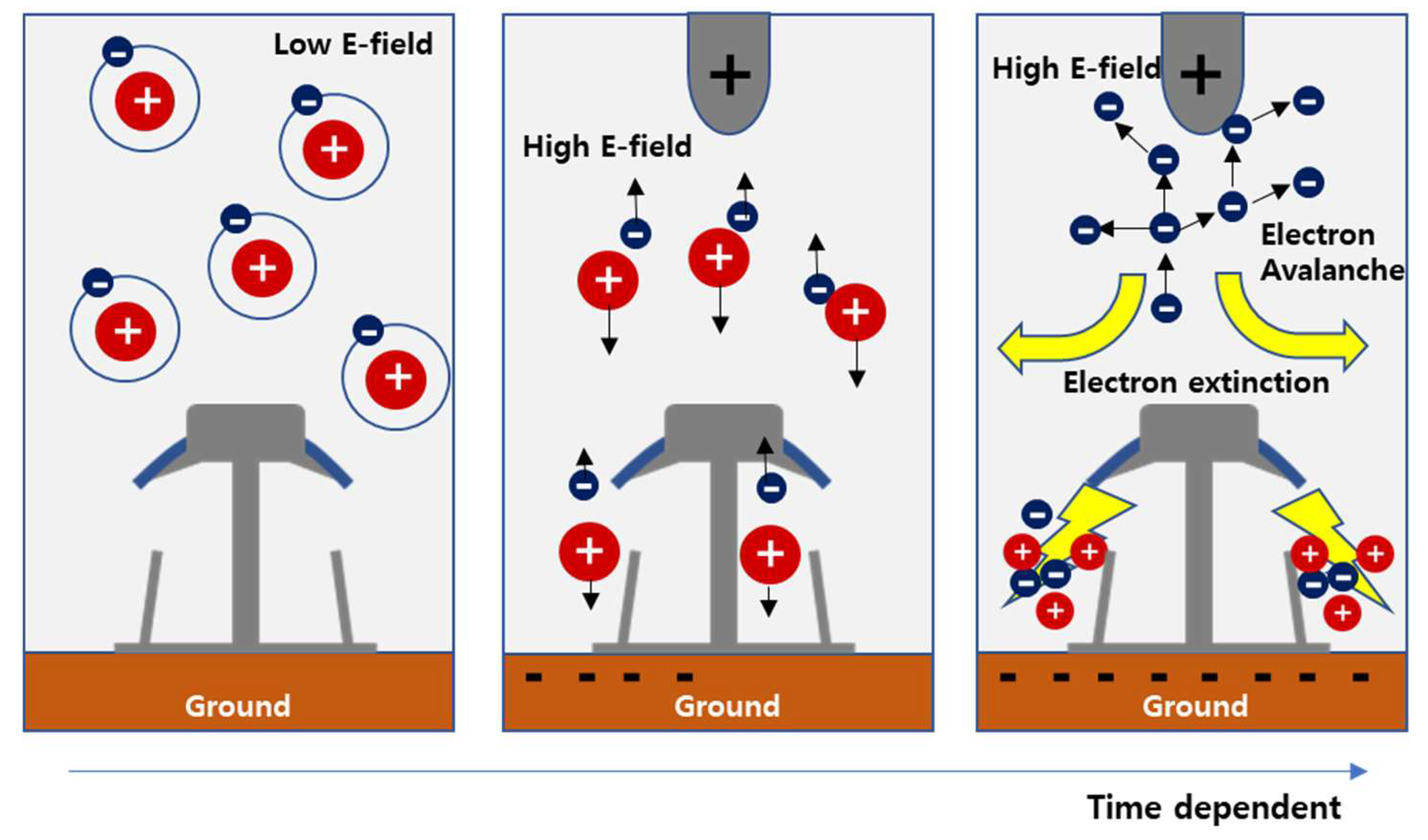
The generated process of the positive and negative ion and free electron is illustrated in
Figure 5. In the case of a low external electric field, the bonding energy between the free electron and positively charged ion in air insulation is larger than that of the external electric field. Therefore, many neutral molecules remain in air. However, in high external electric fields, collisions occur between neutral molecules and then free electrons are accelerated in the high electric field [
12]. The newly generated free electron from the surface of the ionizer conductor and air insulation can play a role as new electron avalanches under a high electric field condition. Some of these secondary electrons will again strike the air insulation, producing tertiary electron [
13]. The possibility of early corona discharge caused by the presence of an ionizer conductor was reviewed in the viewpoint of CTS. In the case of a positive strike occurrence, the surface of the current collector is induced with a negative charge, and the ionizer conductor is positively charged. The electric field between the current collector and the ionizer conductor is distorted, caused by the presence of an ionizer conductor and the ionized free electron emitted from sharp tip of the ionizer conductor under high electric field. Thus, it might be possible that the electric field concentration occurs at the sharp tip of ionizer conductor and it could be the starting point of early corona discharge inception.
Some studies have investigated the early corona discharge between the floating conductor and conducting brushes in terms of experimental results and computer simulation studies according to the presence or absence of a floating conductor [
5,
6]. The experimental results show that a floating conductor system can generate more electrons than without a floating electrode, and the corona discharge can be controlled using a floating conductor [
6]. In our research work, we have focused on the air space over the presence or absence of a floating conductor to control the inception and occurrence position of corona discharge. In the 0.0005 mm air space, the electric field and electron density are concentrated between ionizer conductor and current collector; it could be a starting point of the corona discharge inception. However, when the air space is increased, the electric field concentration and high electron density occurs at the SK-AOR380 tip part. The reason for the inception and occurrence position of the corona discharge according to the air space in the simulation results can possibly be explained by the following empirical factor:
If the air space is too far, the generated free electron could not excite another free electron for the electron avalanche between ionizer conductor and current collector. In other words, the first free electron cannot play a role as the seed of the secondary and tertiary electron avalanches. E. V. Oreshkin et al. [
14] have reported the dependences of the length of exponential enhancement of the runaway electron avalanche on the electric field strength in air insulation, calculated using the Monte Carlo method. W. Riegler et al. [
15] investigated the distance to first ionization under 30 kV/cm,
; a minimum distance for first ionization is required for several
. In this research work, we found the optimized air space using a numerical analysis method while considering relational equations from the above reference papers [
14,
15].
However, the above discussion is just one possibility reviewed from the simulation results as a basic research work. The corona discharge of a narrow air space is a very complicated physical process, affected by many factors. Further work is needed on experiment results for validation from the above research work. In addition, further numerical analysis is needed to consider the neighboring grounded objects. This is because the electric field distribution in the close vicinity of the air terminal is certainly affected by the presence of neighboring grounded objects, at least of the of the protected structure itself.
5. Conclusions
Some studies on the performance of CTS have focused on modification of the structure and shape of the CTS. The air space is designed (>2 mm) as an empirical design without quantitative data. This paper focused on the optimized air space between the ionizer conductor and the ground current collector to improve the performance of the initial corona discharge inception using an FEA software package. To investigate the optimal air space, it was reduced to the extent possible for simulation to a micro size. The electric field strength between the ionizer conductor and current collector increases with a decreasing air space until 0.0005 mm. The electric field strength of 0.0005 mm air space is increased by 1.3 times that of 0.001 mm. The free electron density is concentrated where the peak of the electric field is formed. In particular, the free electron density of 0.0005 mm air space is increased by 1.9 times that of 0.0001 mm. The negative ion density shows a similar trend with positive ion density; the maximum value of both ion densities are formed at 1.34 , 1.32 with different free electron densities. It might be possible that the free electron mobility () has a higher mobility than ions (). However, a air space of less than 2 mm was no longer a significant difference in our simulation results. Thus, the 0.0005 mm air space creates a non-uniform high electric field with a large electric field enhancement due to ionization caused by consecutive electron avalanches. In addition, it might be possible that the high electric field concentration occurs at 0.0005 mm air space, and this could be the starting point of early corona discharge. The results in this paper have been discussed in terms of the electron mean free path. To improve the CTS, we suggest the air space between the ionizer conductor and current collector of less than 2 mm, different from conventional CTS studies.
Author Contributions
K.-H.J. contributed to conceptualization, methodology, analysis, and writing. S.-W.S. contributed to validation, formal analysis, data curation, and visualization. D.-J.K. contributed to review and editing. All authors have read and agreed to the published version of the manuscript.
Funding
This study was supported by the KETEP (Korea Energy Technology Evaluation and Planning). 20215710100360, development of mobile application product technology using re-manufactured batteries.
Institutional Review Board Statement
Not applicable.
Informed Consent Statement
Not applicable.
Data Availability Statement
Not applicable.
Conflicts of Interest
The authors declare no conflict of interest.
References
- Cooray, V. The Similarity of the Action of Franklin and ESE Lightning Rods under Natural Conditions. Atmosphere 2018, 9, 225. [Google Scholar] [CrossRef] [Green Version]
- Becerra, M. The Early Streamer Emission Principle Does Not Work Under Natural Lightning. In Proceedings of the IX International Symposium on Lightning Protection, Foz do Iguaçu, Brazil, 26–30 November 2007. [Google Scholar]
- Cooray, V. Non-Conventional Lightning Protection System. In Proceedings of the 30th International Conference on Lightning Protection (ICLP), Cagliari, Italy, 13–17 September 2010. [Google Scholar]
- Lee, J.-H. Local Electric Field Analysis for Evaluation of Charge Transfer System using Sequential Sub-window Technique. IEEE Trans. Magn. 2004, 40, 679–682. [Google Scholar] [CrossRef]
- Baek, M.K.; Chung, Y.K.; Park, I.H. Experiment and Analysis for Effect of Floating Conductor on Electric Discharge Characteristic. IEEE Trans. Magn. 2013, 49, 2323–2326. [Google Scholar] [CrossRef]
- Chung, Y.-K. Effect of the Corona Shield of the OMNI Bipolar Conventional Air Terminals. In Proceedings of the 2016 International Conference & Workshop on Electromagnetic Interference and Compatibility, Bengaluru, India, 8–9 December 2016. [Google Scholar]
- Steinle, G.; Neundorf, D.; Hiller, W.; Pietralla, M. Two-dimensional simulation of filaments in barrier discharges. J. Phys. D Appl. Phys. 1999, 32, 1350–1356. [Google Scholar] [CrossRef] [Green Version]
- Georghiou, G.; Papadakis, A.P.; Morrow, R.; Metaxas, A.C. Numerical modelling of atmospheric pressure gas discharges leading to plasma production. J. Phys. D Appl. Phys. 2005, 38, R303–R328. [Google Scholar] [CrossRef]
- Potje-Kamloth, K. Biomolecules, Biointerfaces and Applications. In Handbook of Surfaces and Interface of Materials; Elsevier: Amsterdam, The Netherlands, 2001. [Google Scholar]
- Akiyama, H. Streamer discharges in liquids and their applications. IEEE Trans. Dielectr. Electr. Insul. 2000, 7, 646–653. [Google Scholar] [CrossRef]
- Schmidt, W.F. Electronic Conduction Processes in Dielectric Liquids. IEEE Trans. Electr. Insul. 1984, EI-19, 389–418. [Google Scholar] [CrossRef]
- Syssoev, A.; Iudin, D.; Iudin, F.; Klimashov, V.; Emelyanov, A. On the Problem of Critical Electric Field of Atmospheric Air. Atmosphere 2021, 12, 1046. [Google Scholar] [CrossRef]
- Tanaka, T. Analysis of Electric Charge Accumulation in Polymeric Insulation by Quantum Chemical Calculation. In Proceedings of the Annual Meeting of The Institute of Engineers of Japan, Tokyo, Japan, 19 October 2015. [Google Scholar]
- Oreshkin, E.V.; Barengolts, S.A.; Oreshkin, V.I.; Chaikovski, S.A. Characteristics Length and Enhancement Time of a Runway Electron Avalanche in Strong Electric Fields. Tech. Phys. Lett. 2012, 38, 604–608. [Google Scholar] [CrossRef]
- Riegler, W.; Schindler, H.; Veenhof, R. Avalanche Statistics. In Proceedings of the RD51 Collaboration Meeting, Paris, France, 13–15 October 2008. [Google Scholar]
| Disclaimer/Publisher’s Note: The statements, opinions and data contained in all publications are solely those of the individual author(s) and contributor(s) and not of MDPI and/or the editor(s). MDPI and/or the editor(s) disclaim responsibility for any injury to people or property resulting from any ideas, methods, instructions or products referred to in the content. |
© 2023 by the authors. Licensee MDPI, Basel, Switzerland. This article is an open access article distributed under the terms and conditions of the Creative Commons Attribution (CC BY) license (https://creativecommons.org/licenses/by/4.0/).


