

Ballpoint/Rollerball Pens: Writing Performance and Evaluation

Department of Chemical and Biological Engineering, Illinois Institute of Technology, Chicago, IL 60616, USA
*
Author to whom correspondence should be addressed.
Colloids Interfaces 2023, 7(2), 29; https://doi.org/10.3390/colloids7020029
Submission received: 6 March 2023
/
Revised: 29 March 2023
/
Accepted: 31 March 2023
/
Published: 4 April 2023
(This article belongs to the Special Issue Fundamental and Applied Aspects of Nanofluids)
Abstract
:Here, a brief history of the development of the ballpoint/rollerball pen and the fountain pen is presented. Their principle of operation is analogous that of multipart microfluidics-type devices, where capillarity–gravity drives the ink, a complex fluid, to flow in the confinement of a micrometer-sized canal or to lubricate a ball rotating in a socket. The differences in the operational writing principles of the fountain pen versus the ballpoint/rollerball pen are discussed. The ballpoint/rollerball pen’s manner of writing was monitored using lens end fiber optics and was digitally recorded. The ball rotation rate per unit length was monitored using a piezoelectric disk oscilloscope technique. The role of ink (a complex fluid) chemistry in the wetting phenomenon is elucidated. We also discuss methods for studying and evaluating ink–film–ball–paper surface wetting. The goal of the proposed research is to optimize and improve the writing performance of the ballpoint/rollerball pen.

1. Introduction
“Verba volant, scripta manent” (Calus Titus).
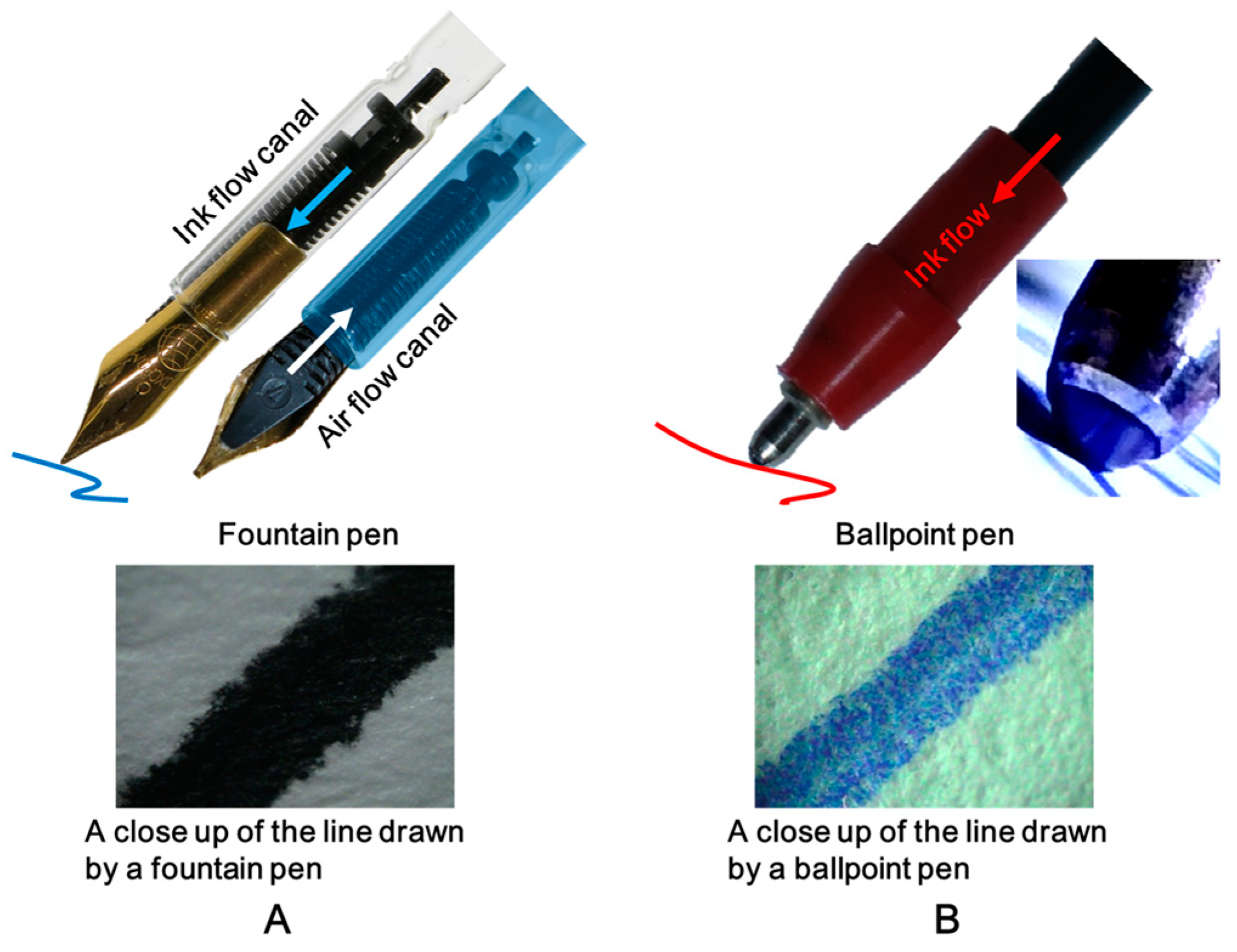
The development of writing changed the world and began a new era of civilization. Humans used spoken languages for a hundred thousand years before they were inspired to mark their ideas down and preserve knowledge for future civilizations. Handwriting devices, such as those used with clay tablets (tokens) and papyrus, were used to write symbols expressing verbal meaning [1]. These early devices included tools with a sharp triangular tip, reed-like pens, and pens made from a goose or swan feather. Before the current fountain pen design appeared, many people contributed to its development, including Aristotle (384–332 BC) and Leonardo da Vinci (1452–1519) [2]. Fountain pen lovers are usually hobby enthusiasts who enjoy pen writing and calligraphy. The price of a fountain pen with good writing performance is more than USD 100, much more expensive than the popular USD 1 ballpoint/rollerball pen. To evaluate the cost of the writing performance of fountain pens and ballpoint pens, the design and operating principles were investigated. Figure 1 depicts the main features of fountain pens and ballpoint pens.
The two handwriting devices’ operations are analogous to multipart microfluidics-type devices in which capillarity–gravity drives the ink, a complex fluid, to flow in the confinement of a micrometer-sized canal or to lubricate a ball rotating in a socket. They have a common feature: the delivery of ink through hydrostatic pressure. However, the ink delivery mechanisms for writing are very different: a nib with a slit versus a ball in a socket. The fountain pen’s ink–paper writing, i.e., the ink–cartridge–feeder–nib–slit and the air bubble capillary valve, were described by us in a recently published paper [3]. The fountain pen ink feeder (the unit between the ink cartridge and nib) has two canals: an ink canal and an air canal (see Figure 1A). During writing, the ink flows from the cartridge through the ink feeder canal to the nib slit. Once the holding air pressure builds up in the cartridge, the ink flow is reduced and stopped. To continue the ink flow while writing, the air holding pressure in the ink cartridge needs to be reduced. The air bubble has to move through the air flow canal in the ink cartridge. When the holding air pressure is reduced, the ink flows through the canal to the nib slit as writing continues. The process of the air bubble moving into the ink cartridge has to be regulated over time. If the air bubble is not moving regularly, the ink flow will stop. This could be one common reason that some fountain pens do not work well throughout their writing time, often resulting in ink spills or stains on the paper. Fountain pen writing performance depends on variations in temperature and pressure. The dynamics of the air bubble flow in the canal makes the fountain pen a complex device. Fritz studied the effect of fountain pen ink properties on the amount of ink used by fountain pens during handwriting [4]. She found that the ink wetness was highly dependent on surface tension. However, the ballpoint pen is a device that is somewhat less complex than the fountain pen. The ink flows from the ink tube to a tiny metal ball in a bearing socket. During writing, the ball in the socket rotates and is coated with ink. During writing, the ink from the ball’s surface wets the paper’s fibers, and an ink streak with a white patch (i.e., a region only partially covered with) in the middle appears (see Figure 1B), resulting in non-smooth ink writing. The writing with ink on paper depends on the physicochemical properties of the ink and paper as well as the speed of the pen [5].
The development of the ballpoint pen has a long history. The first patent was issued on 30 October 1888, to John Loud. The invention had leaks and caused smearing. Later, Brio and his brother improved on Loud’s invention and patented the invention (there were still problems with ink leakage, however). The invention was cheap and became popular in 1944. Baron Marcel Bich’s ballpoint pen invention solved the ink leakage issue, and he began manufacturing BIC ballpoint pens in Paris. Over the years, many technological improvements were made to achieve better ballpoint pen writing performance, including with respect to the ink viscosity, ball material, ball size, and ball surface properties, to improve the delivery of ink onto the paper. The ballpoint pen’s manner of writing and the rheology of the ink are different from those of the fountain pen. The ballpoint pen is less dependent on variations in atmospheric pressure when delivering ink onto paper, and is considerably less expensive than its counterpart, which has motivated consumers to prefer ballpoint pens to fountain pens. Therefore, the ballpoint/rollberball pen has become the most popular handwriting tool in the world. However, the ink, ink line smoothness, writing constancy, ball pressure, and ergonomics still need improvement.
2. Experimental Section
2.1. Monitoring Ballpoint Pen Writing Performance by Lens End Fiber Optics
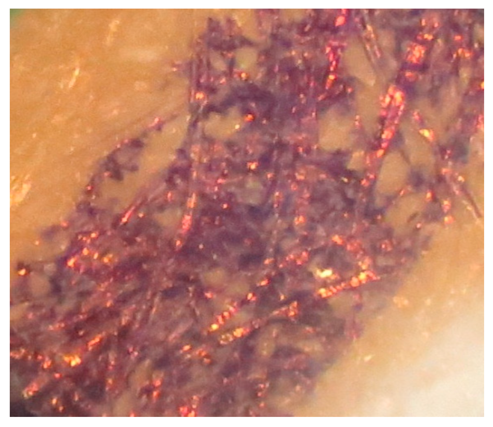
To understand the ballpoint pen’s writing performance, ink–ball–paper writing was monitored. A lens end fiber optical device was designed. The fiber optics end lens connected to the computer was used to monitor ink–ball–paper transfer. Appendix A Video Clip 1 (Supplementary Materials) depicts the ballpoint ink writing dynamics. For confidentiality reasons, we do not disclose the brand of the ball and ink pen that we used. The video reveals details of the ballpoint pen’s writing. The ball in its socket is in contact with the ink in the cartridge. The ink’s molecular chemical composition helps ink wet the ball surface via adhesion, and the ball surface is coated with several micrometer-thick ink film. The ball ink film coating process occurs quickly. During writing, the ball rotates and the micron-thick ink film comes in contact with paper fibers. The ink film on the ball surface has to be homogeneous in thickness and not rupture before contact with the paper fiber. The ink film on the ball surface in contact with the paper fibers becomes unstable, and then breaks, forming an ink streak. The texture and the smoothness of the ink streak on the paper determine the ballpoint pen’s writing performance. The above discussion was based on a theoretical model of ballpoint pen writing. Appendix A Video Clip 1 reveals that the ink film coated on the ball appears to be nonhomogeneous in thickness, and the ink streak texture is also not smooth. Moreover, the middle of the streak has a white stain domain, with a region with much less ink (see Figure 1B). The ink–ball–paper fiber partial wettability is a possible explanation for the ink streak’s roughness (see Figure 2).
To improve the ink streak’s smoothness, the ink–ball–fiber wettability needs to be improved by adding the appropriate wetting agent into the ink composition. Making the ink wet both the metal ball’s surface and the chemically pretreated cellulose fiber is not an easy task, and it requires knowledge of the wetting dynamics. Ink–ball–fiber wetting is a dynamic process. The ball coating is governed by the dynamic contact angle and ink rheology. For the modeling of ink–ball–fiber wetting-coating dynamics, data about the capillary number () and Reynolds number () are needed. This will be discussed in the “Fundamentals” section.
The nature of the white stain domain in the ink streak is also related to the ink–paper wettability (see Figure 1B). Why is the ink so sparse there? The ballpoint pen’s writing is accomplished by the rotating ball coated with the ink film. The effect of the ball’s downward pressure on the ballpoint pen’s writing performance has to be considered as a factor. When the ball coated with the ink film makes contact with the paper, the ink film from the ball surface wets the surface of the paper fiber. The microphotograph presented in Figure 1B is cropped from the frames of Appendix A Video Clip 1, where the white stain domain appears during writing. A possible explanation is the ink film on the ball coming into contact with the breaks in the paper fiber, causing the ink stain domain to appear. The modeling of ballpoint pen writing quality requires the analysis of the stability of the curved asymmetric ink film in contact with two different phases (e.g., metal ball–paper) under writing pressure.
To view the mechanism of the ballpoint pen’s writing, video monitoring was conducted using a ballpoint pen with a small ball and low-viscosity ink (see Appendix B Video Clip 2). The video depicts the writing dynamics of a rollerball pen. The ball’s surface was well coated with ink film, and the ink streak on the paper was smooth, without speckles. A potential undesirable effect of writing is when the ink leaks around the ball and partially spills on the paper when the ball stops moving.
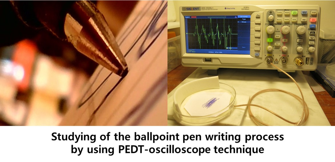
In addition to the fiber optic video monitoring of the ballpoint pen–ink writing dynamics, a piezoelectric disk transducer (PEDT) covered with a sheet of paper was used. Technical information about the PEDT was presented in our previous study [6]. The ballpoint pen–ink writing process was performed using a one-millimeter metal ball placed in a bearing socket. The upper part of the ball was in contact with the ink container. Ballpoint pen writing is a random rolling process comprising a normal ball–paper pressure stress, ball transition, ball rotation, ball–ink–paper adhesion, and ball friction (see Appendixs A and B Video Clips 1 and 2). To elucidate the role of these processes, the writing study was conducted over the PEDT covered with paper and connected to the oscilloscope.
2.2. Monitoring Ballpoint Writing Using a Piezoelectric Disk Transducer (PEDT)
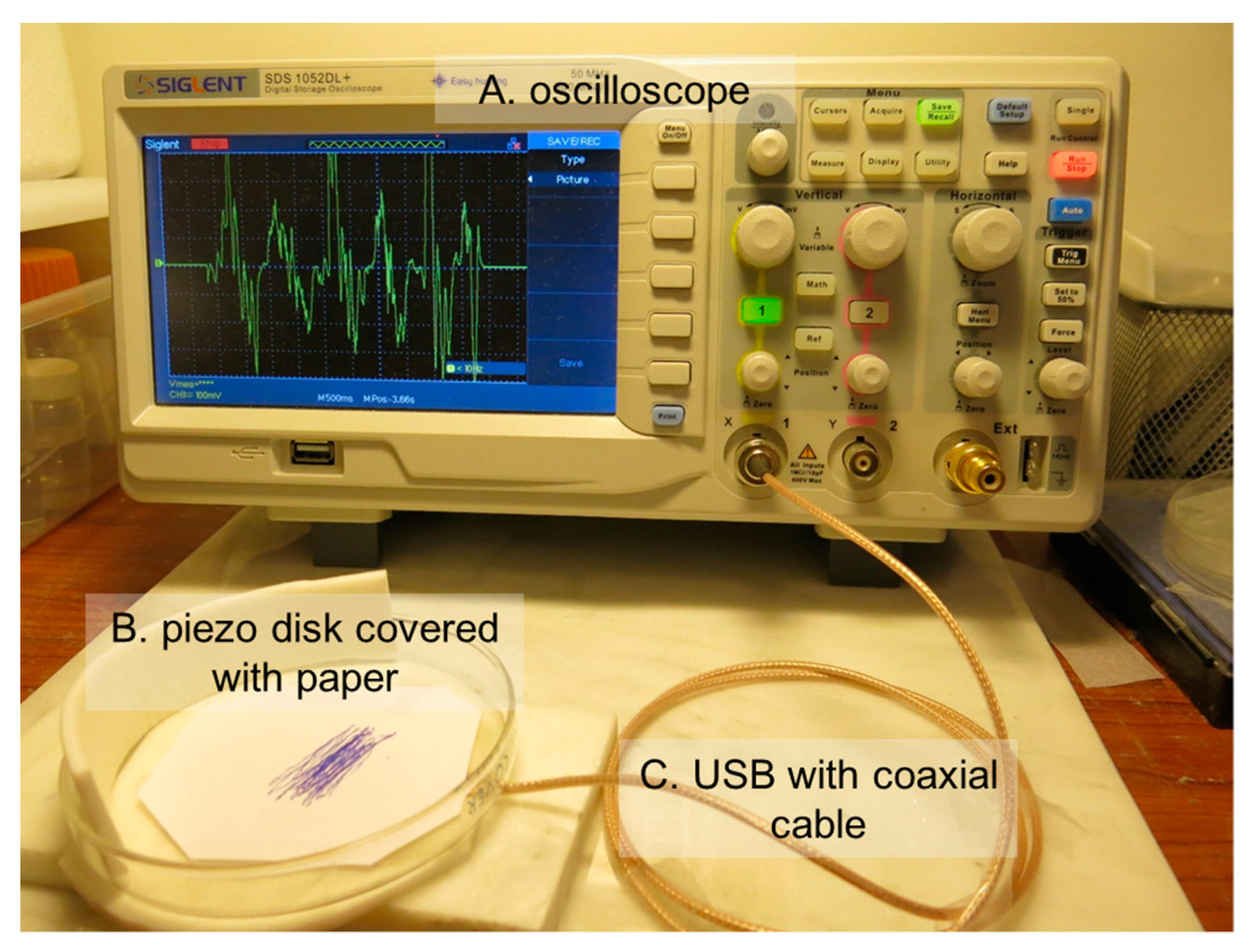
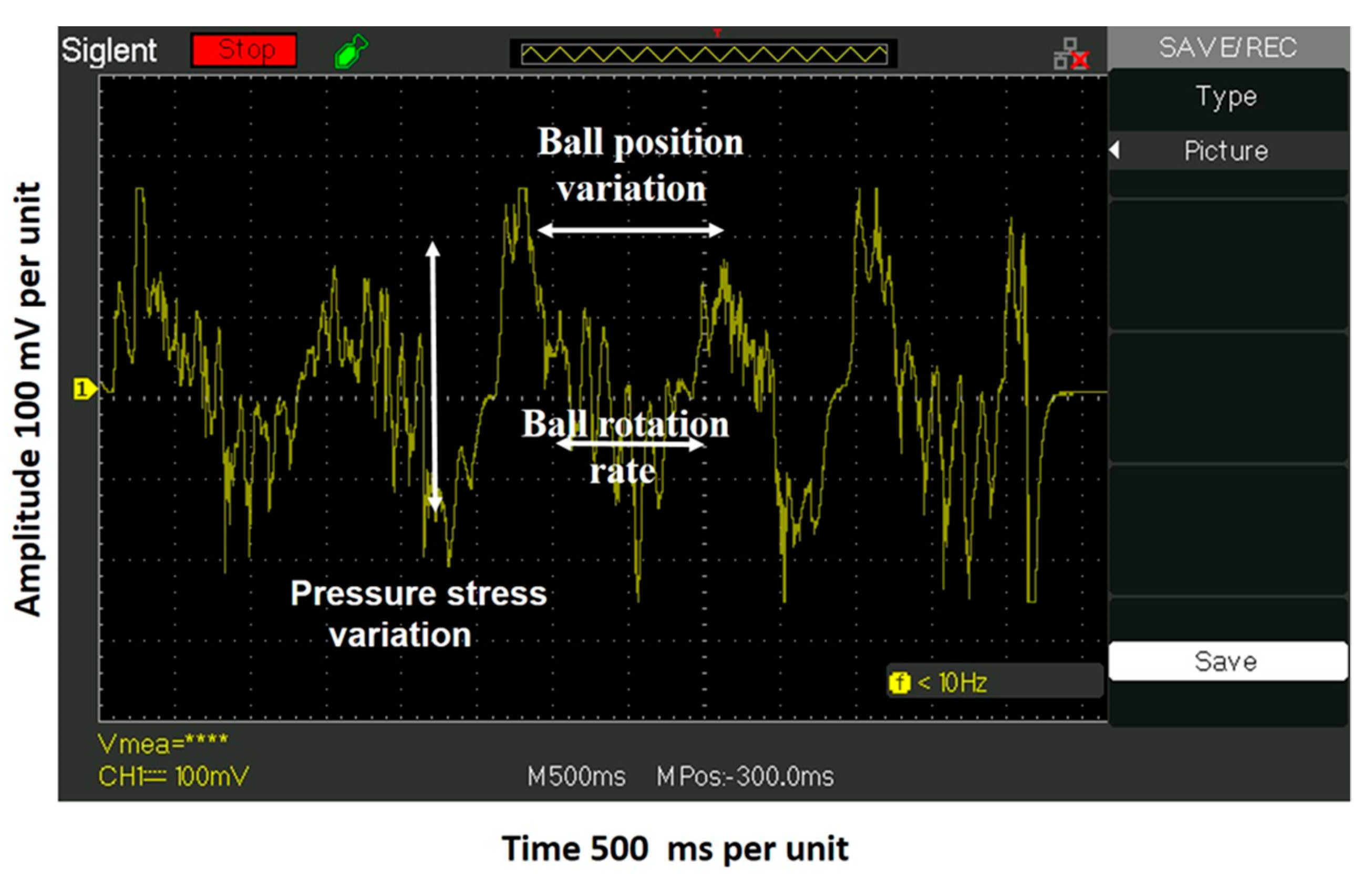
Ballpoint pen writing requires normal stress, is a random rolling process, and is specific for each person. During writing, the ballpoint pen moves and rotates over the PEDT, and the local pressure stress varies with the ball’s position. The PEDT–oscilloscope technique is a sensitive device and is used to monitor the pressure variation in the rolling ball mechanical stress over the writing time. The photo of the experimental setup is presented in Figure 3: the PEDT is wired to the oscilloscope to monitor the ballpoint pen writing on the paper.
To test the PEDT response to monitor the ballpoint pen’s writing, the mechanical stress pressure of the free rolling ball on the paper was monitored. A polished clean steel metal ball with size of 1 cm was used. The metal ball weight (size) was chosen to mimic the normal pressure of a ballpoint pen during the handwriting process. Figure 4 depicts the PEDT–oscilloscope oscillatory pressure stress signal during the free downward roll of the metal ball over the paper on a 5–10° inclined transducer disk with a frequency of 190 Hz.
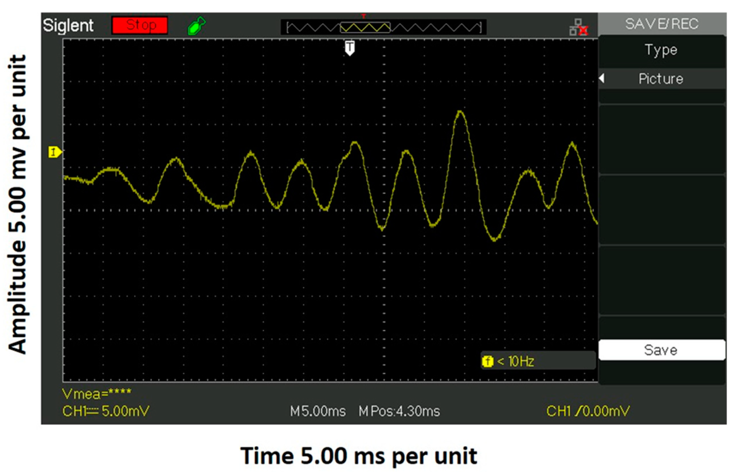
The test indicated that the PEDT oscilloscope technique was capable of monitoring the ball transition and rotation motion and is applicable for monitoring the writing process of ballpoint pens (i.e., the normal mechanical pressure stress variation of the ball, ball transition, ball rotation, and friction). Figure 5 depicts the ballpoint pen’s writing position over time in frequency. The ballpoint pen writing test was conducted with a 1.6 mm ball size. The normal mechanical pressure stress variation versus time was 450 ± 40 mV/per unit, the ballpoint pen position movement in frequency was 0.8 ± 0.15 Hz, and the velocity was 1.5 cm per 0.62 s. The calculation of the normal pressure variation of the ball in Pa units requires the assumption of the average ball–paper contact area during writing and needs modeling.
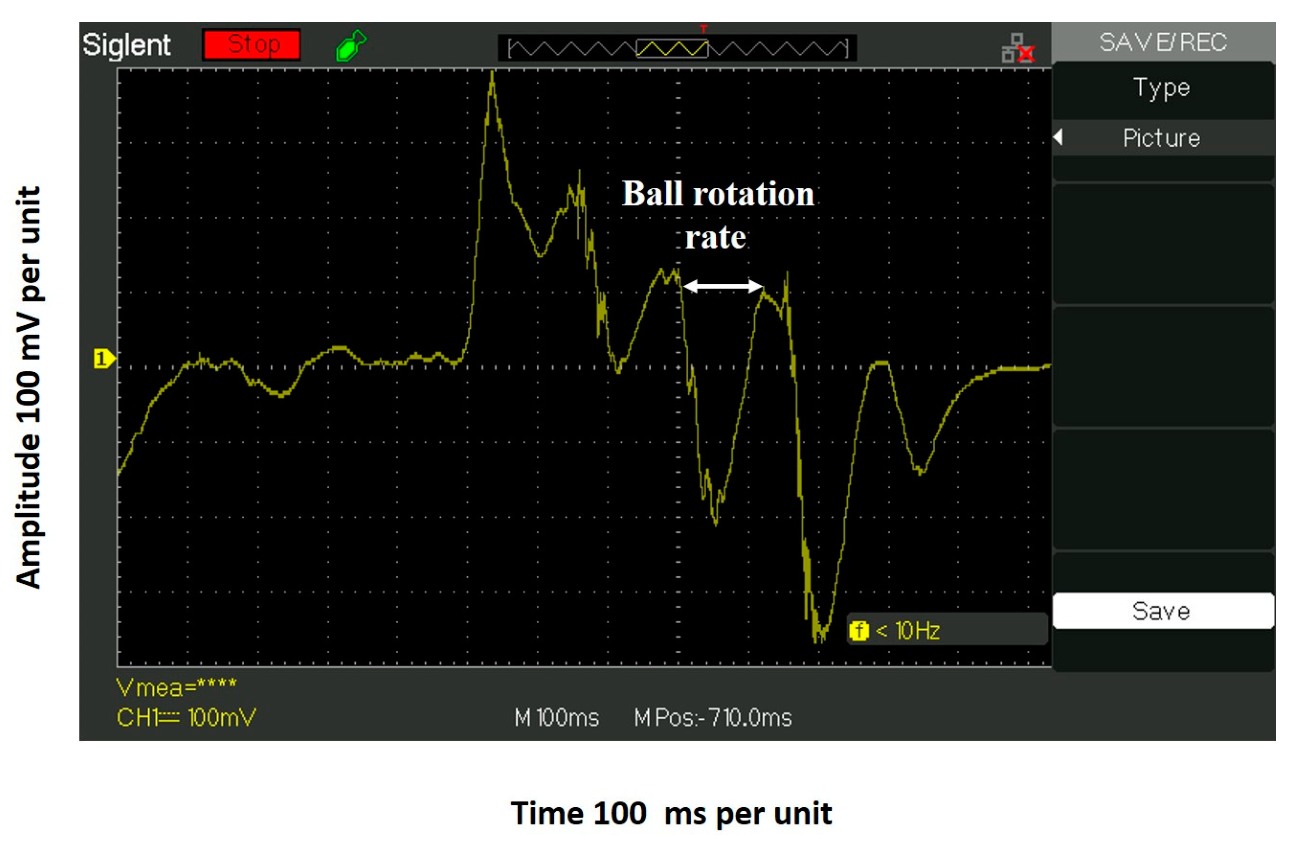
For visualization, the ball rotation rate section in frequency presented in Figure 5 is expanded and presented in Figure 6. Assuming no rotation slip, the estimated ball rotation frequency is 6.7 ± 0.5 Hz, and the ball rotation rate is 4.8 rev/s.
Observation also reveals that over the signal produced by the ball rotation rate is an oscillatory superposition signal-like noise with a small amplitude and a high frequency of several kHz. This is likely due to the friction of ball rotation in the socket. This requires further study.
3. Fundamentals
Improving ballpoint/rollerball pen writing performance requires an understanding of the phenomenon complexity and the governing factors: the dynamics of ball–complex fluid (ink) wetting, ball–ink film coating, and the coating–ball–ink film–paper fiber interactions. Ballpoint ink is a complex fluid and is made of a mixture of 25–40% dye or pigment suspended in a combination of oil and fatty acids, such as oleic acid acting as lubricant, allowing the ball to spin without tension. The oils include benzyl alcohol or phenoxyethanol [7]. Here, we first briefly discuss the concept of a simple fluid wetting a solid. To improve ballpoint writing performance, it is necessary to perform studies on the rheology of the ink and the wetting dynamics of the ink in ballpoint pens. The methodology to apply to improve the ballpoint writing performance is described below.
3.1. Classical Concept of Fluid-Wetted Solid
The classical concept of a fluid-wetted solid is based on the energy of wetting and is quantified by the three-phase contact angle () (see Figure 7).
When a simple fluid drop is placed on a smooth, energy-ideal solid (e.g., a sessile droplet), before it reaches its equilibrium shape and forms the macroscopic equilibrium three-phase contact angle, the droplet reduces its free energy by changing shape and three-phase contact angle due to the actions of the gravitational, capillary, and interfacial forces. Two types of contact angle are defined in the three-phase contact region: the macroscopic angle (the contact angle at the intersection of the extrapolated three interfaces, called the “Laplace contact angle”) and the microscopic angle (defined as the angle between the molecular self-layering film and the solid) [8]. To explain a simple liquid wetting a solid, two classical models have been proposed: the thermodynamic model, corresponding to the adsorbed layer/film macroscopic contact angle on the solid, and the hydrodynamic model, addressing the capillary dynamics in consideration of the dynamic contact angle.
3.2. Three-Phase Contact Angle Defined by the Force Balance Model
Here, a brief review of the classic wetting concept relating to the macroscopic contact angle is presented. Young [9] and Laplace [10] were among the first to propose the macroscopic three-phase contact angle concept based on the force model. The macroscopic three-phase contact angle equation was derived from a thermodynamic assumption. The virtual work of the minimization of the surface free energies per unit area () is based on three pure phases (solid, liquid, and gas), and the equilibrium macroscopic three-phase contact angle () when the relationship between the solid surface free energies of the three phases (solid, liquid, and gas (liquid vapor)) are taken into consideration. Young [9] proposed treating the three equilibrium pure phase contact angles of a droplet on a non-deformable, smooth, stress-free solid (ideal solid) surface as the result of the mechanical equilibrium between the three surface/interfacial energies and macroscopic contact angle () with the relationship:
where , , and are the surface free energies (solid/gas, solid/liquid, and gas/liquid). This equation does not consider the role of the force operating along the three-phase contact line (known as the “line tension”). Dupre [11] introduced the reversible work of adhesion () to separate the liquid from the ideal solid exposed to the liquid vapor with the relation:
Equation (2) is a thermodynamic expression in which the reversible work of separating the liquid and the ideal solid is equal to the change in the free energy of the system. By combining Equations (1) and (2), for the Young–Dupre equation of the adhesion free energy at the solid/liquid interface was obtained:
The three-phase contact angle force model approach is good to evaluate the ink–solid–air equilibrium interaction energy and ink ball solid wettability, and is valid only for simple fluids. Ballpoint pen writing is a dynamic process and requires the application of the dynamic contact angle approach. The classical concept of a single fluid-wetted solid cannot be applied when modeling complex fluids, such as an ink film coating a solid (ball). The ink–ball–paper wetting dynamics is one of the essential factors in ballpoint pen writing performance.
3.3. Complex Molecular Fluid Wetting Solid via the Hydrodynamic Model
Hydrodynamic models for the wetting of a solid have been proposed by Huh and Scriven [12], Cox [8], Voinov [13], and Dussan [14]. In the thermodynamic model, the liquid film on a liquid-wetted solid is at equilibrium with the equilibrium macroscopic contact angle, and the fluid is considered to be a continuum. The hydrodynamic model proposed by Brochard-Wyart and De Gennes [15] considers the lubrication approach for the small macroscopic contact angle viscous energy dissipation in the bulk and neglects liquid–solid interaction at the molecular level.
where is the capillary number, is the molecular cut-off below which the continuum theory breaks down, and is the macroscopic cut-off proportional to the radius of curvature of the meniscus. The ratio is the scaling parameter.
The molecular kinetic model proposed by Cherry and Holmes [16] considers the wetting process to be an activated rate process. The model assumes that the three-phase contact line (TPCL) moves between the successive positions of the equilibrium across the intervening activation energy barriers when the wetting liquid moves on a solid. The resulting differential equation for the time-dependent dynamic contact angle is as follows:
where is the time-dependent dynamic contact angle, is the distance between the positions of equilibrium, is the dimensions of the jumping unit in the direction parallel to the three-phase boundary, is the displacement volume of the unit of flow, and is the viscosity. Although there are three unknown parameters, and the fitted value from the spreading of the polymer melt seems unreasonably large, this was the first attempt to theoretically model spreading dynamics. Blake et al. [17,18] proposed a molecular kinetic theory based on Eyring’s activated rate theory considering the adsorption and desorption dynamics of liquid molecules on solid surface near the TPCL.
The molecular kinetic theory can be applied to a wide range of equilibrium contact angles. However, for a small equilibrium contact angle, the prediction is not as good as that from the hydrodynamic model [19]. While the molecular kinetic theory shows the significance of the solid surface properties in dynamic wetting, it overlooks the effect of the shape of the liquid molecules, which is also important, as shown in this work and in the literature [20]. Molecular/complex fluids wetting solid driven by self-layering is discussed in detail in the work of Wu et al. [21] and Nikolov et al. [22].
3.4. Empirical Model
In addition to the theoretical models, there are also some empirical equations relating to the dynamic contact angle and capillary number. Newman [23] analyzed the rate of the penetration of polymer melt into the capillaries and proposed Equation (6) to correct the effect of the time-dependent dynamic contact angle.
where is the time-dependent dynamic contact angle, and and are the adjusting parameters.
Jiang et al. [24] correlated the experimental data of a liquid displacing air through a glass capillary. They proposed the relation between the dynamic contact angle and the capillary number when gravity and inertia can be neglected:
Joos et al. [25] measured the dynamic advancing contact angle when a continuous solid strip was drawn into a large liquid pool and obtained the following empirical equation:
They incorporated this equation into the Lucas–Washburn equation, and found a good fit with the complex fluid of silicone oil wetting glass capillaries [26,27].
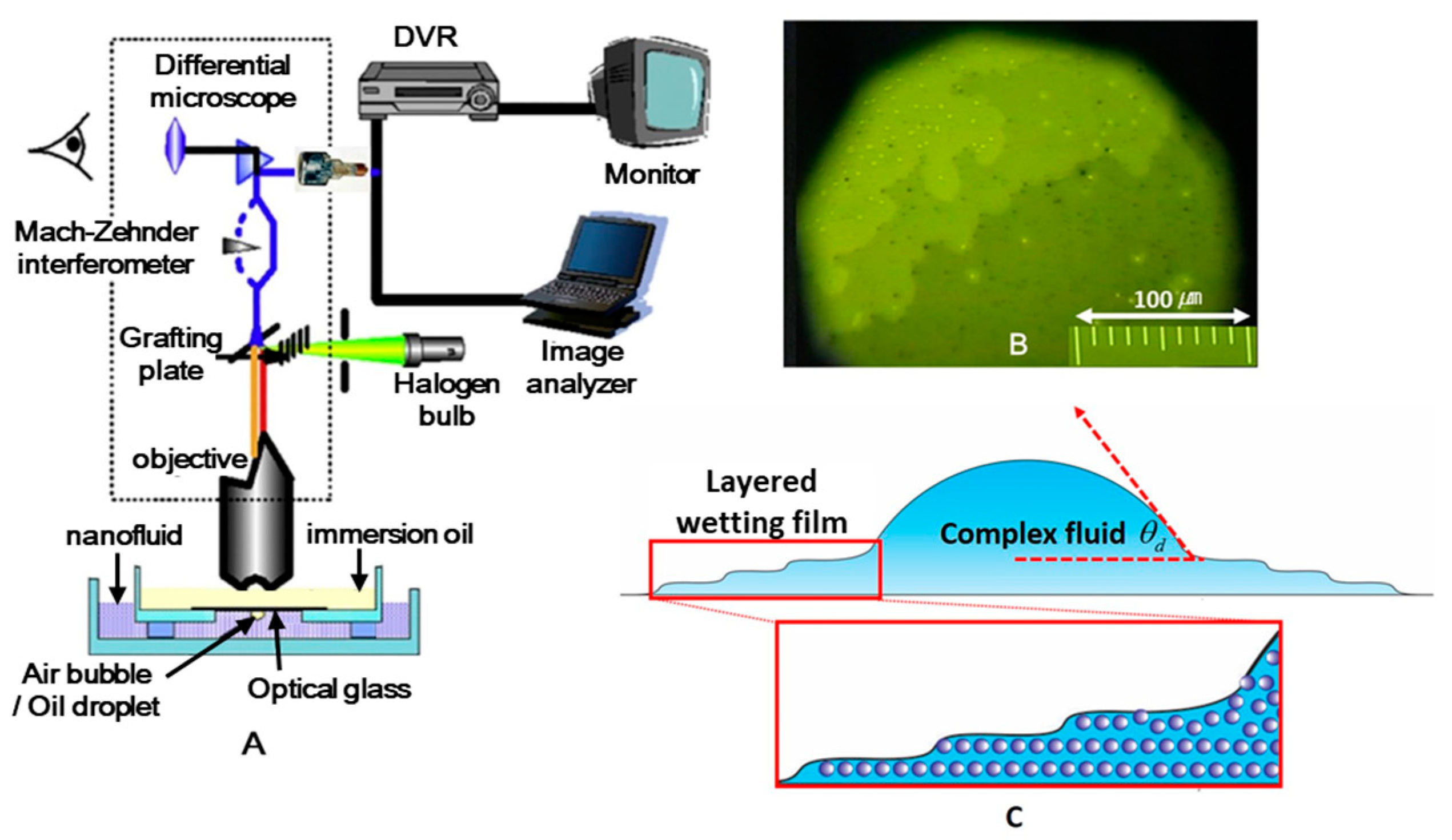
None of the models explicitly show how the dynamic contact angle depends on the velocity of the TPCL. Therefore, a better understanding of the physics of the dynamic contact angle is required. Recent studies [28,29,30] have shown that for wetting liquids, there is a molecularly thin film ahead of the moving TPCL. Molecular simulations [31,32] indicated that the formation of the film is faster than the movement of the TPCL. As a result, the droplet slides on the wetting film. Therefore, the contact line and contact angle between the droplet meniscus and the wetting film should be called the “apparent contact line” and the “apparent contact angle”. It was found that close to the surface, nano-suspensions such as ballpoint pen ink are self-layered [33,34,35] and even form inlayer structures under the film confinement [36,37]. The experimental setup—a differential reflected light microscope (DRLM) to study the complex fluid-wetted solid surface and create micrographs depicting the complex (nano-fluid) step-wetting layering phenomenon—is presented in Figure 8. The optical principles of operation of the DRLM are presented elsewhere [38,39].
4. Conclusions
Ballpoint pen writing is a random rolling process comprising a normal ball–paper pressure stress, ball transition, ball rotation, ball–ink–paper adhesion, and ball friction.
Observation reveals that the writing performance of the ballpoint/rollerball pens is not smooth, and the ink streak texture (see Figure 1B) has a white stain domain, indicating the need for ink-film-wetting optimization.
To improve the ballpoint pen’s writing performance, additional studies on the rheology of ink and the wetting dynamics of ink ballpoint pens are required.
The proposed solid wetting dynamic methods can be applied to optimize ink–film–ball–paper wetting.
Ballpoint pen ergonomics require optimization.
Supplementary Materials
The following supporting information can be downloaded at: https://www.mdpi.com/article/10.3390/colloids7020029/s1, Video S1: The writing dynamics of the ballpoint pen’s ink; Video S2: The ballpoint pen–ink writing process.
Author Contributions
Writing—reviewing the draft and editing figures, J.L.; Writing—reviewing the draft, S.M.; Conceptualization and Writing—original draft, A.N. All authors have read and agreed to the published version of the manuscript.
Funding
This research received no external funding.
Data Availability Statement
The data presented in this study are available on request from the corresponding author.
Conflicts of Interest
The authors declare no conflict of interest.
Appendix A
Video Clip 1 description
Video Clip 1 depicts the writing dynamics of the ballpoint pen’s ink (the ball size is 1.6 mm). (For confidentiality, we do not include the commercial name of the pen, and the ink type is not discussed.) The ballpoint pen and the lens end fiber optics were attached to a holding stand to monitor the writing process. During the writing process, the ball rotates and is coated with the ink film. The ink on the ball’s surface wets the paper surface, and an ink streak forms. The video reveals details of the ballpoint pen’s writing process: the metal ball’s rotation rate, the quality of the ink–ball–film coating, and the ink streak on the paper. The texture and the smoothness of the ink streak on the paper determine the ballpoint pen’s writing performance. The ink film coated onto the metal ball appears to have a nonhomogeneous thickness, and so the ink streak texture is not smooth.
Appendix B
Video Clip 2 description
Video Clip 2 depicts the ballpoint pen ink writing process with a ball size of 0.5 mm. We used the same technique to monitor the writing process as used in Video Clip 1. (For confidentiality, we do not include the commercial name of the pen, and the ink type is not discussed.) The rotating ball’s surface is coated with a regular ink film with a thickness of several regular microns, and the ink streak on the paper is smooth without speckles. However, when the writing rate is reduced or stopped, an ink spill appears along the ball–paper contact region.
References
- Fischer, S.R. History of Writing; Reaktion Books: London, UK, 2001. [Google Scholar]
- da Vinci, L. Codex Leicester (A Collection of Scientific Writings); Manuscript; 1510; pp. 1504–1508. [Google Scholar]
- Nikolov, A.; Murad, S.; Wasan, D.; Wu, P. How the capillarity and ink-air flow govern the performance of a fountain pen. J. Colloid Interface Sci. 2020, 578, 660–667. [Google Scholar] [CrossRef]
- Fritz, I. Identification of fountain pen ink properties which determine the amount put on paper during handwriting. Mater. Des. 2022, 219, 110739. [Google Scholar] [CrossRef]
- Kim, J.; Moon, M.-W.; Lee, K.-R.; Mahadevan, L.; Kim, H.-Y. Hydrodynamics of writing with ink. Phys. Rev. Lett. 2011, 107, 264501. [Google Scholar] [CrossRef]
- Nikolov, A.; Wasan, D. Air bubble bursting phenomenon at the air-water interface monitored by the piezoelectric-acoustic method. Adv. Colloid Interface Sci. 2019, 272, 101998. [Google Scholar] [CrossRef]
- Nardo, S.D. How Do Ballpoint Pens Work. Available online: https://www.dayspringpens.com/blogs/the-jotted-line/how-do-ballpoint-pens-work (accessed on 10 February 2023).
- Cox, R. The dynamics of the spreading of liquids on a solid surface. Part 1. Viscous flow. J. Fluid Mech. 1986, 168, 169–194. [Google Scholar] [CrossRef]
- Young, T., III. An essay on the cohesion of fluids. Philos. Trans. R. Soc. Lond. 1805, 95, 65–87. [Google Scholar]
- Laplace, P. Traité de mécanique céleste, Supplement to the 10th Book; Duprat: Paris, France, 1807. [Google Scholar]
- Dupré, A.; Dupré, P. Théorie Mécanique de la Chaleur; Gauthier-Villars: Paris, France, 1869. [Google Scholar]
- Huh, C.; Scriven, L.E. Hydrodynamic model of steady movement of a solid/liquid/fluid contact line. J. Colloid Interface Sci. 1971, 35, 85–101. [Google Scholar] [CrossRef]
- Voinov, O. Hydrodynamics of wetting. Fluid Dyn. 1976, 11, 714–721. [Google Scholar] [CrossRef]
- Dussan, V. On the difference between a bounding surface and a material surface. J Fluid Mech 1976, 75, 609–623. [Google Scholar] [CrossRef]
- Brochard-Wyart, F.; De Gennes, P. Dynamics of partial wetting. Adv. Colloid Interface Sci. 1992, 39, 234501. [Google Scholar] [CrossRef]
- Cherry, B.W.; Holmes, C.M. Kinetics of wetting of surfaces by polymers. J. Colloid Interface Sci. 1969, 29, 174–176. [Google Scholar] [CrossRef]
- Blake, T.D. The physics of moving wetting lines. J. Colloid Interface Sci. 2006, 299, 1–13. [Google Scholar] [CrossRef]
- Blake, T.; Haynes, J. Kinetics of liquidliquid displacement. J. Colloid Interface Sci. 1969, 30, 421–423. [Google Scholar] [CrossRef]
- Katoh, K.; Wakimoto, T.; Yamamoto, Y.; Ito, T. Dynamic wetting behavior of a triple-phase contact line in several experimental systems. Exp. Therm. Fluid. Sci. 2015, 60, 354–360. [Google Scholar] [CrossRef]
- Shanahan, M.E.; Houzelle, M.-C.; Carré, A. Strange spreading behavior of tricresyl phosphate. Langmuir 1998, 14, 528–532. [Google Scholar] [CrossRef]
- Wu, P.; Nikolov, A.; Wasan, D. Capillary dynamics driven by molecular self-layering. Adv. Colloid Interface Sci. 2017, 243, 114–120. [Google Scholar] [CrossRef]
- Nikolov, A.; Wu, P.; Wasan, D. Structure and stability of nanofluid films wetting solids: An overview. Adv. Colloid Interface Sci. 2019, 264, 1–10. [Google Scholar] [CrossRef]
- Newman, S. Kinetics of wetting of surfaces by polymers; capillary flow. J. Colloid Interface Sci. 1968, 26, 209–213. [Google Scholar] [CrossRef]
- Jiang, T.-S.; Soo-Gun, O.; Slattery, J.C. Correlation for dynamic contact angle. J. Colloid Interface Sci. 1979, 69, 74–77. [Google Scholar] [CrossRef]
- Bracke, M.; De Voeght, F.; Joos, P. The kinetics of wetting: The dynamic contact angle. In Trends in Colloid and Interface Science III; Springer: Berlin/Heidelberg, Germany, 1989; pp. 142–149. [Google Scholar]
- Joos, P.; Vanremoortere, P.; Bracke, M. The Kinetics of Wetting in a Capillary. J. Colloid Interface Sci. 1990, 136, 189–197. [Google Scholar] [CrossRef]
- Vanremoortere, P.; Joos, P. The Kinetics of Wetting—the Motion of a 3 Phase Contactline in a Capillary. J. Colloid Interface Sci. 1991, 141, 348–359. [Google Scholar] [CrossRef]
- Beattie, D.A.; Espinosa-Marzal, R.M.; Ho, T.T.; Popescu, M.N.; Ralston, J.; Richard, C.l.J.; Sellapperumage, P.M.; Krasowska, M. Molecularly-thin precursor films of imidazolium-based ionic liquids on mica. J. Phys. Chem. C 2013, 117, 23676–23684. [Google Scholar] [CrossRef]
- Ausserré, D.; Picard, A.; Léger, L. Existence and role of the precursor film in the spreading of polymer liquids. Phys. Rev. Lett. 1986, 57, 2671. [Google Scholar] [CrossRef]
- Hoang, A.; Kavehpour, H.P. Dynamics of Nanoscale Precursor Film near a Moving Contact Line of Spreading Drops. Phys. Rev. Lett. 2011, 106, 254501. [Google Scholar] [CrossRef] [Green Version]
- Yuan, Q.Z.; Zhao, Y.P. Precursor Film in Dynamic Wetting, Electrowetting, and Electro-Elasto-Capillarity. Phys. Rev. Lett. 2010, 104, 246101. [Google Scholar] [CrossRef]
- Chibbaro, S.; Biferale, L.; Diotallevi, F.; Succi, S.; Binder, K.; Dimitrov, D.; Milchev, A.; Girardo, S.; Pisignano, D. Evidence of thin-film precursors formation in hydrokinetic and atomistic simulations of nano-channel capillary filling. EPL 2008, 84, 44003. [Google Scholar] [CrossRef] [Green Version]
- Israelachvili, J.N. Intermolecular and Surface Forces, 3rd ed.; Academic Press: Cambridge, MA, USA, 2011. [Google Scholar]
- Christenson, H.; Gruen, D.; Horn, R.; Israelachvili, J. Structuring in liquid alkanes between solid surfaces: Force measurements and mean-field theory. J. Chem. Phys. 1987, 87, 1834–1841. [Google Scholar] [CrossRef] [Green Version]
- Horn, R.G.; Israelachvili, J.N. Direct measurement of structural forces between two surfaces in a nonpolar liquid. J. Chem. Phys. 1981, 75, 1400–1411. [Google Scholar] [CrossRef]
- Chu, X.; Nikolov, A.; Wasan, D. Monte Carlo simulation of inlayer structure formation in thin liquid films. Langmuir 1994, 10, 4403–4408. [Google Scholar] [CrossRef]
- Wasan, D.T.; Nikolov, A.D. Spreading of nanofluids on solids. Nature 2003, 423, 156–159. [Google Scholar] [CrossRef]
- Nikolov, A.D.; Dimitrov, A.S.; Kralchevsky, P.A. Accuracy of the Differential-interferometric Measurements of Curvature. Opt. Acta Int. J. Opt. 1986, 33, 1359–1368. [Google Scholar] [CrossRef]
- Dimitrov, A.; Kralchevsky, P.; Nikolov, A.; Wasan, D.T. Contact angles of thin liquid films: Interferometric determination. Colloids Surf. 1990, 47, 299–321. [Google Scholar] [CrossRef]
Figure 1.
Design and principles of the writing of a fountain pen (A) and a ballpoint pen (B). Lines from each device are shown in the close-up photos of the ink streaks on the paper beneath the pen images.
Figure 1.
Design and principles of the writing of a fountain pen (A) and a ballpoint pen (B). Lines from each device are shown in the close-up photos of the ink streaks on the paper beneath the pen images.

Figure 2.
Microphotograph of the ink–paper streak speckled texture caused by the ink-fiber partial wettability.
Figure 2.
Microphotograph of the ink–paper streak speckled texture caused by the ink-fiber partial wettability.

Figure 3.
Photo of the experimental setup: PEDT–oscilloscope and the signal produced by ballpoint pen ink writing on the paper attached to the piezoelectric transducer. (A) Oscilloscope, (B) piezo disk covered with paper, (C) USB with coaxial cable.
Figure 3.
Photo of the experimental setup: PEDT–oscilloscope and the signal produced by ballpoint pen ink writing on the paper attached to the piezoelectric transducer. (A) Oscilloscope, (B) piezo disk covered with paper, (C) USB with coaxial cable.

Figure 4.
The PEDT–oscilloscope oscillatory pressure stress signal depicted during the free down roll of the metal ball over the paper on a 5–10° inclined transducer disk with a frequency of 190 Hz.
Figure 4.
The PEDT–oscilloscope oscillatory pressure stress signal depicted during the free down roll of the metal ball over the paper on a 5–10° inclined transducer disk with a frequency of 190 Hz.

Figure 5.
The signal produced by the ballpoint pen writing on paper attached to the PEDT oscilloscope, with a ball size of 1.6 mm. The oscillatory signal parts are marked as follows: the pressure stress variation, ball position variation, and ball rotation rate.
Figure 5.
The signal produced by the ballpoint pen writing on paper attached to the PEDT oscilloscope, with a ball size of 1.6 mm. The oscillatory signal parts are marked as follows: the pressure stress variation, ball position variation, and ball rotation rate.

Figure 6.
The expanded region of the ball rotation rate in frequency.

Figure 7.
Classical concept of fluid-wetted solid. Surface free energies (: solid/gas, : solid/liquid, and : gas/liquid) and three-phase contact angle ().
Figure 7.
Classical concept of fluid-wetted solid. Surface free energies (: solid/gas, : solid/liquid, and : gas/liquid) and three-phase contact angle ().

Figure 8.
(A) Sketch of the optical arrangement: the differential reflected light microscope to monitor complex fluid film layer-wetted solid surface. (B) Microphotograph of aqueous silica suspension: volume fraction 0.40 and nano particle size 80 nm on the solid surface. (C) A cross-section sketch of the complex fluid film layer-wetted solid.

Disclaimer/Publisher’s Note: The statements, opinions and data contained in all publications are solely those of the individual author(s) and contributor(s) and not of MDPI and/or the editor(s). MDPI and/or the editor(s) disclaim responsibility for any injury to people or property resulting from any ideas, methods, instructions or products referred to in the content. |
© 2023 by the authors. Licensee MDPI, Basel, Switzerland. This article is an open access article distributed under the terms and conditions of the Creative Commons Attribution (CC BY) license (https://creativecommons.org/licenses/by/4.0/).
Share and Cite
MDPI and ACS Style
Lee, J.; Murad, S.; Nikolov, A. Ballpoint/Rollerball Pens: Writing Performance and Evaluation. Colloids Interfaces 2023, 7, 29. https://doi.org/10.3390/colloids7020029
AMA Style
Lee J, Murad S, Nikolov A. Ballpoint/Rollerball Pens: Writing Performance and Evaluation. Colloids and Interfaces. 2023; 7(2):29. https://doi.org/10.3390/colloids7020029
Chicago/Turabian StyleLee, Jongju, Sohail Murad, and Alex Nikolov. 2023. "Ballpoint/Rollerball Pens: Writing Performance and Evaluation" Colloids and Interfaces 7, no. 2: 29. https://doi.org/10.3390/colloids7020029