Article

On Classification of Water-in-Oil and Oil-in-Water Droplet Generation Regimes in Flow-Focusing Microfluidic Devices

by
Ampol Kamnerdsook
1,
Ekachai Juntasaro
1,*,
Numfon Khemthongcharoen
2,
Mayuree Chanasakulniyom
3,
Witsaroot Sripumkhai
2,
Pattaraluck Pattamang
2,
Chamras Promptmas
4,
Nithi Atthi
2 and
Wutthinan Jeamsaksiri
2
1
Mechanical Engineering Simulation and Design Group, The Sirindhorn International Thai-German Graduate School of Engineering (TGGS), King Mongkut’s University of Technology North Bangkok, Bangkok 10800, Thailand
2
National Electronics and Computer Technology Center (NECTEC), National Science and Technology Development Agency (NSTDA), Pathum Thani 12120, Thailand
3
Center for Standardization and Product Validation, Faculty of Medical Technology, Mahidol University, Nakhon Pathom 73170, Thailand
4
Department of Biomedical Engineering, Faculty of Engineering, Mahidol University, Nakhon Pathom 73170, Thailand
*
Author to whom correspondence should be addressed.
Colloids Interfaces 2023, 7(1), 17; https://doi.org/10.3390/colloids7010017
Submission received: 30 December 2022 / Revised: 31 January 2023 / Accepted: 17 February 2023 / Published: 20 February 2023
(This article belongs to the Special Issue Fundamental and Applied Aspects of Nanofluids)

Abstract

:
The objective of this research work is to propose a phase diagram that can be used to find a proper operating condition for generating droplets of different types. It is found that the phase diagram of QR versus CaD can effectively classify the droplet generation into three vivid regimes: dripping, jetting and tubing. For the dripping regime, its operating condition is in the range of either CaD < 10−4 and QR < 50 or 10−3 < CaD < 10−4 and QR < 1. For the jetting regime, its operating condition is in the range of either CaD < 1.35 × 10⁻² and QR > 100 or CaD > 1.35 × 10⁻² and QR > 1. For the tubing regime, its operating condition is in the range of CaD > 1.35 × 10⁻² and QR < 1.

Graphical Abstract

1. Introduction

Nowadays microfluidics plays a key role in a wide range of research in the field of medicine, cosmetics, food and agriculture. Microfluidics is of generating monodispersed droplets with the ability to control the size precisely. Therefore, it is widely used in biomedical applications such as drug delivery [1,2,3], cell biology [4,5,6,7,8], chemical reaction [9,10] and microparticle production [11,12,13,14,15]. For droplet generation, a dispersed-phase fluid is injected into a continuous-phase fluid. At the interface, there are two types of shear stresses involved: (1) the wall shear stress between the dispersed-phase fluid and the micro-channel surface and (2) the fluid shear stress due to the volume flow rate of the continuous-phase fluid. Once these two shear stresses overcome the interfacial tension, droplets can be formed.
Micro-channels commonly used to generate droplets in microfluidics can be classified into 3 types: (1) the T-junction micro-channel, (2) the flow-focusing micro-channel and (3) the co-flow micro-channel. The T-junction micro-channel [16,17,18] is the simplest one to generate droplets and design. It consists of one dispersed-phase inlet and one continuous-phase inlet, and both inlets are perpendicular together. However, it is not effective as far as controlling droplet generation is concerned when compared to the flow-focusing micro-channel and the co-flow micro-channel. The flow-focusing micro-channel [19,20,21,22,23,24,25,26,27,28,29,30,31,32,33,34,35,36] is composed of one dispersed-phase inlet and two continuous-phase inlets. The dispersed-phase inlet is perpendicular to both continuous-phase inlets at the junction where a balance of the fluid shear stresses is obtained. The co-flow micro-channel [37,38,39,40,41,42,43,44] has one dispersed-phase inlet, which looks similar to a capillary tube, inside a continuous-phase micro-channel through both of which the dispersed- and continuous-phase fluids flow in parallel to each other. The efficiency of the flow-focusing micro-channel is equivalent to that of the co-flow micro-channel. However, in design, there is a wide variety of flow-focusing micro-channels available with more potential surface modification compared with the co-flow micro-channel. Therefore, this research mainly focuses on the flow-focusing micro-channel.
For the design and optimization of a droplet-based microfluidic device to generate droplets with high throughput and monodispersity, there are various parameters to be considered: the geometry and surface property of a micro-channel, fluid properties of both phases, and the interface interaction between a micro-channel and a fluid. For example, the variations of the fluid viscosity and the channel aspect ratio can give rise to different droplet generation regimes [45,46]. The varying surface property of a micro-channel significantly affects droplet generation due to the changing contact angle at the channel wall [47,48]. The surface property of PDMS is normally hydrophobic, and it can be modified from a hydrophobic to a hydrophilic surface by using chemical coating processes by altering the contact angle [49,50]. There were some previous studies on the effects of surface wettability on flow patterns at the cross-junction by varying the amount of surfactants to adjust the contact angle, in which it was found that surfactants affected the droplet formation [51,52].
Since there are several parameters involved in the design of droplet-based microfluidics devices, some dimensionless parameters have been proposed for the identification of various droplet generation regimes. Anna and Mayer (2006) [53] studied the effect of surface tension on droplet generation in various droplet generation regimes using a flow-focusing geometry where the surface tension is varied by adjusting the bulk concentration of the C12E8 surfactant. After plotting the capillary number (Ca) over a range of Ca = 0.1–1.0 versus the volume flow rate ratio (QR), four droplet generation regimes were found: geometry-controlled, thread formation, dripping and jetting. Utada et al. (2007) [54] also investigated two droplet generation regimes (dripping and jetting) by mainly varying the volume flow rate. It was found that the dripping droplet generation regime occurred at a relatively lower flow rate whereas the jetting droplet generation regime was encountered at a relatively higher flow rate. The experimental data were then plotted using the capillary number of the continuous phase versus the Webber number of the dispersed phase, and the two droplet generation regimes were obtained at different viscosity ratios. Cubaud and Mason (2008) [55] studied the relationship between Ca of the dispersed phase and Ca of the continuous phase for the classification of different droplet generation regimes by varying the viscosity ratio and the interfacial tension (γ). Derzsi et al. (2012) [56] categorized droplet generation into three main droplet generation regimes: without satellites, single satellites and multiple satellites, by using various fluids for the dispersed phase and the continuous phase to vary Ca. Van Loo et al. (2016) [57] studied the effects of the interfacial tension on droplet generation in different droplet generation regimes by adding the surfactant (FC-40 fluorocarbon oil mixed with PFO surfactant) and adding no surfactant (silicone oil only), where Ca of the continuous phase was adjusted by varying the flow rate ratios of both phases. Palagan et al. (2020) [58] investigated the effects of surface modification on droplet generation in different droplet generation regimes using chemical coating with polyacrylic acid where the hydrophobic PDMS surface (CA = 100°) was modified to be hydrophilic (CA = 55°). The phase diagram of droplet generation was created for both water-in-oil droplets of the hydrophobic surface and oil-in-water droplets of the hydrophilic surface using the relationship between the flow rate ratio and the capillary number of the continuous phase. The previous related works concerning the phase diagram of droplet generation are summarized in Table 1.
From previous works mentioned above, there are three main parameter groups that influence droplet formation in different droplet generation regimes: (1) fluid properties, (2) flow rate and channel geometry and (3) surface properties and surfactant solution. For fluid properties, the fluid viscosities of both phases are significant. For flow rate and channel geometry, these two parameters can be replaced inclusively by the fluid velocity (i.e., v = Q/A where v is the fluid velocity, Q is the volume flow rate, and A is the channel cross-section area). For surface properties and surfactant solution, these two parameters directly affect the interfacial tension, and therefore the capillary number Ca is used as the dimensionless parameter to identify the different droplet generation regimes. To reduce the number of parameters, these physical parameters are formulated into a few dimensionless parameters, such as Ca, We and QR. For double-emulsion droplet generation, a selection of proper droplet generation regimes to be used and their suitable operating condition can increase the encapsulation efficiency. However, double-emulsion droplet generation consists of two separate parts: the water-in-oil part and the oil-in-water part. Comparing both parts reveals that their capillary numbers are considerably different. Therefore, the characteristics and identification of the water-in-oil part and oil-in-water parts are different. Based on previous research works, almost all of them considered the identification and classification of droplet generation regimes from the viewpoint of water-in-oil droplet generation only. The main objective of this research is to construct the phase diagram of water-in-oil and oil-in-water droplet generation regimes at various droplet generation conditions depending on the type of droplet, geometry, fluid properties, flow rate and surface properties. Experimental conditions used for droplet generation are collected from previous works [22,24,31,33,34,36,57,58,59,60,62,63,64] and the present work to cover a wide range of Ca and to vividly classify various droplet generation regimes.

2. Materials and Methods

2.1. Materials

PDMS (Dow Corning, Sylgard 184 Elastomer Kit, Midland, MI, USA) is used to fabricate the current microfluidic device. The micro-channel surface is modified by permanent chemical coating for which the surfactant solution was a mixture of Pluronic F-127 (Sigma Aldrich, St. Louis, MO, USA) and Ethanol (Sigma Aldrich). Each water-in-oil droplet comprises (1) DIW mixed with the red-color dye at the ratio of 1.0% w/w for the dispersed phase (QD) in order to enhance the flow visualization inside the micro-channel and (2) mineral oil (SKYDD, AA-1086768) mixed with Span 80 (Sigma Aldrich) at the ratio of 0.5% w/w for the continuous phase (QC). Each oil-in-water droplet comprises (1) mineral oil (SKYDD, AA-1086768) for the dispersed phase and (2) DIW mixed with Triton X-100 (Sigma Aldrich) at the ratio of 2.0% w/w for the continuous phase.

2.2. Equipment

The solutions of the dispersed and continuous phases are injected into the microfluidic device through silicone tubes (Cole Parmer, 0.02″ i.d., Vernon Hills, IL, USA) and disposable syringes (NIPRO, 1.0 ML, Osaka, Japan) using three syringe pumps (NE-1000, New Era Pump System, Inc., Farmingdale, NY, USA) at the flow rates is a range of 10–200 µL h−1. The image of generated droplets and the monitoring screens at two junctions inside the micro-channels are captured by the optical microscope (OLYMPUS BX51M, Shinjuku City, Tokyo, Japan) with a CCD camera (HAYEAR, 5.0MP CMOS, Futian, Shenzhen, China).

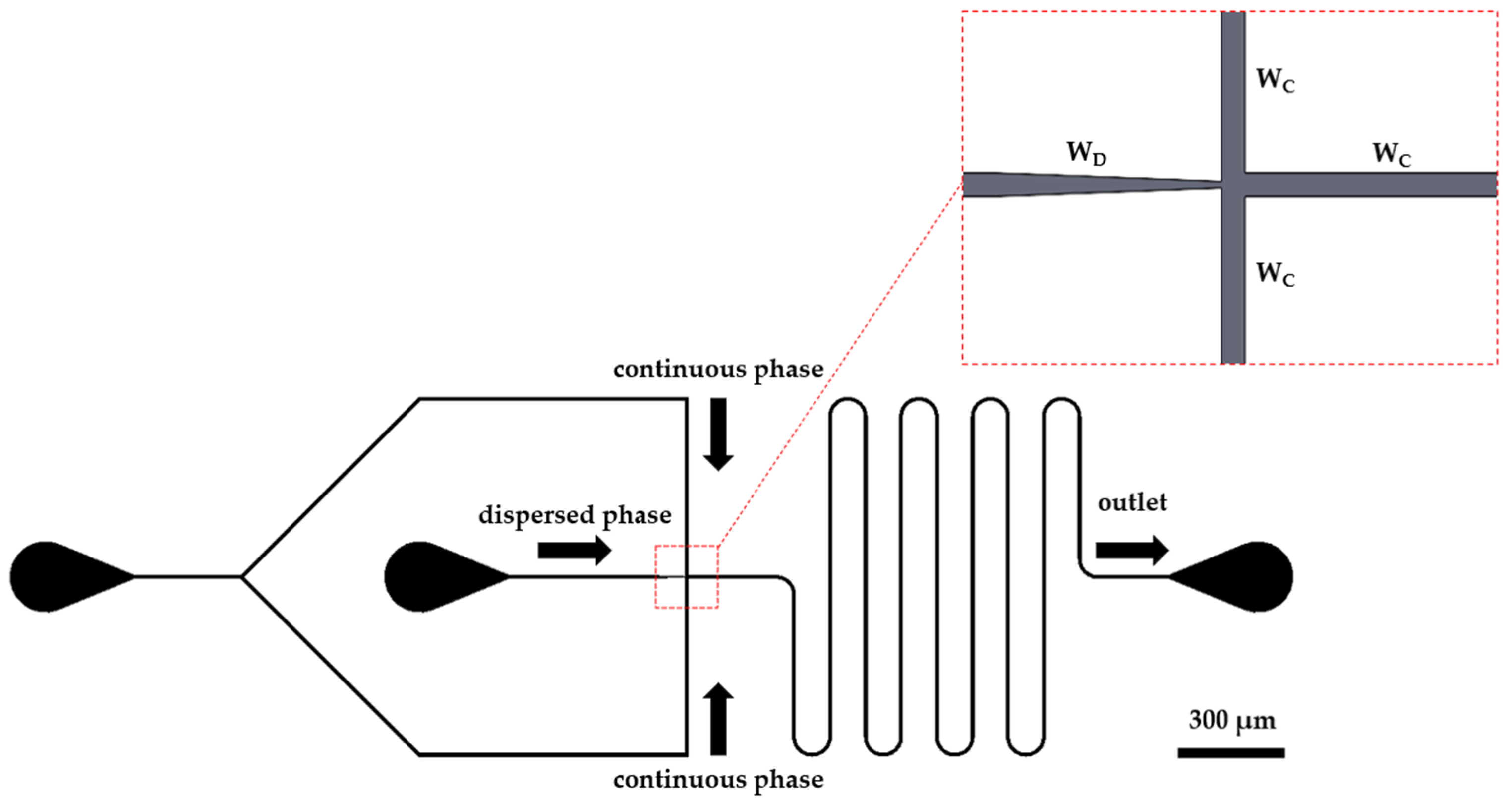
2.3. Microfluidic Device Design

The current droplet-based microfluidic device is designed by using the flow-focusing micro-channel technique as shown in Figure 1. This single-emulsion droplet-based device is used to form water-in-oil (W/O) and oil-in-water (O/W) droplets. There are two inlets (dispersed-phase inlet and continuous-phase inlet) and one outlet. The channel width is equal to 20, 25 and 50 µm for the dispersed phase (WD) and 20, 100, 125 and 150 µm for the continuous phase (WC). At the dispersed-phase inlet, the channel width is reduced from WC to WD over the length of 1 mm. The channel height is equal to 50 and 100 µm for the entire device.

2.4. Silicon Master Mold Fabrication

For the silicon master mold fabrication, a 6-inch silicon wafer (Si-wafer) is cleaned by dipping in a piranha acid solution in order to remove organic contaminants from the surfaces of the Si-wafer. Then, the dehydration bake is performed at 200 °C for 100 s. After that, the Si-wafer is primed by using a vapor of hexamethylsilaxane (HMDS) at 80 °C for 45 s to improve a photoresist (PR) adhesion. A commercially available PR, PFI34a (Sumitomo Corporation, Chiyoda City, Tokyo, Japan), is spin-coated at 1000 rpm for 20 s and softbake at 90 °C for 100 s to obtain a thickness of 2.0 μm, and the channel patterns are prepared by a conventional photolithography method using a mask aligner (EVG 620, EV Group, Sankt Florian am Inn, Austria). The spin-coated wafer is exposed to a 365 nm UV light through a plastic photomask. The UV-light intensity is 40 mW/cm2, and the exposure time is 5 s. The feature size on the plastic mask ranges from 40 µm to 120 µm. The Si-wafer is post-exposure baked (PEB) at 110 °C for 100 s to eliminate the standing wave effects on the sidewall of the PR patterns, then developed in SD-W, Sumitomo Corporation, for 75 s, and hard baked at 120 °C for 80 s. Afterwards, the photo-patterned Si-wafer is etched via a deep-reactive ion etcher (DRIE, Oxford instruments, Abingdon, UK) with a Bosch etching process using SF6/C4F8 gases. The remaining PR is stripped with oxygen plasma and piranha acid solution for 10 min. Then the Si master mold is rinsed with DIW for 10 min and blown dry with pure N2 gas.

2.5. Microfluidic Device Fabrication and Surface Modification

Microfluidic devices are fabricated by conventional soft lithographic techniques. Polydimethylsiloxane (PDMS) precursor and a curing agent are mixed at a ratio of 10:1 w/w. The PDMS mixture is poured on top of the patterned silicon wafers, degassed and cured at 75 °C for 90 min. After curing for 12 h, the cured PDMS is peeled off from the Si-master, cut and punched to connect silicone tubes. The microfluidic devices are assembled by directly bonding to the flat sheet of cured PDMS stripped off a blank wafer after surface treatment. The surface treatment is carried out with an oxygen plasma under 40 sccm of O2 with 30 Watts for 90 s.
There are three types of surface properties of microfluidic devices used in the present work: (1) hydrophobic micro-channel, (2) hydrophilic micro-channel and (3) partially hydrophobic/hydrophilic micro-channel [65]. For the hydrophobic micro-channel, its surface is not modified because PDMS is used to make the micro-channel and its surface property is hydrophobic by nature. For the hydrophilic micro-channel, its surface is modified by the chemical coating method using the surfactant solution obtained by mixing Pluronic F-127 of 200 g and ethanol of 1.0 mL, flowing this surfactant solution into the micro-channel and keeping the micro-channel and the solution together overnight. For the partially hydrophobic/hydrophilic micro-channel, the microfluidic device is fabricated with the surface modification using the permanent chemical coating method where the same surfactant solution as in the chemical coating method is used to mix with PDMS during the soft lithography process. The detail of the droplet-based microfluidic device geometry (unit in µm) and surface properties is shown in Table 2.

2.6. Experimental Setup

The capillary number (Ca) is defined as the ratio of the viscous force to the interfacial tension, which is an important dimensionless parameter for the classification of droplet generation regimes. Ca can be determined by Equation (1).
C a = v μ γ
where v is the average velocity of droplets, μ is the dynamic viscosity and γ is the interfacial tension.
The Weber number (We) is defined as the ratio of the inertia force to the interfacial tension. We can be determined by Equation (2).
W e = ρ v 2 D h γ
where ρ is the fluid density and D h is the hydraulic diameter of the micro-channel cross-section.
The volume flow rate ratio (QR) is defined as the ratio of the continuous-phase flow rate (QC) to the dispersed-phase flow rate (QD), which is a dimensionless parameter used to describe the fluid flow rates of dispersed and continuous phases. QR can be expressed by Equation (3).
Q R = Q C Q D
The experiment of single-emulsion droplet generation for the study of droplet generation regime classification is conducted by two different microfluidic devices: (1) for water-in-oil droplets without modified surface and (2) for oil-in-water droplets with modified surface. For water-in-oil single-emulsion droplet generation, Ca of the dispersed phase (CaD) is in a range of 1.53 × 10⁻⁵–3.39 × 10⁻², while Ca of the continuous phase (CaC) is in a range of 1.59 × 10⁻⁸–9.06 × 10⁻². For oil-in-water single-emulsion droplet generation, CaD is in a range of 3.62 × 10⁻⁴–1.19, whereas CaC is in a range of 4.51 × 10⁻¹⁰–3.82 × 10⁻³. For all considered experimental conditions, Ca is adjusted by varying the volume flow rates of both phases for which the volume flow rate ratio is obtained over a range of 0.001–1000. For each experiment, it begins with an initial run of at least 30 min before recording the data in order to ensure that the equilibrium state is obtained in each micro-channel. However, after several repeating experiments, some micro-channels can potentially be damaged and a new microfluidic device is required. Therefore, in order to re-use the microfluidic device many times, micro-channels need cleaning by flashing DI water into the microfluidic device and then blowing air into it to dry micro-channels. For droplet generation in tubing, dripping and jetting regimes, three experiments are typically conducted at each condition. However, five experiments are performed instead for the two transition zones (dripping-jetting zone and dripping-tubing zone) at each condition. The reproducibility of the results in tubing, dripping and jetting regimes must be 100%, while that of the two transition zones must not be less than 80%, i.e., the same results for 4 times out of 5 experiments.

2.7. Experimental Data from Previous Works of Several Research Groups

The existing experimental data from previous works reported by several research groups are also collected by considering only those related to droplet generation using a flow-focusing junction. Pannacci et al. [20] generated oil-in-water droplets using the fluorinated oil mixed with silicone oil for the oil phase and the water with SDS 1% w/w for the water phase. The micro-channel was made with modified surface using an O2 plasma. Abate et al. [21] made oil-in-water-in-oil droplets using the fluorocarbon oil for the inner phase and the DI-water with SDS 0.5% w/w for the outer phase. Bauer et al. [22] generated water-in-oil-in-water droplets using the DI water, the fluorous oil with EA 2% w/w and the DI water with SDS 0.5% w/w for the inner phase, the middle phase and the outer phase, respectively. The micro-channel with modified surface was obtained by chemical coating method. Li et al. [31] made water-in-oil-in-water droplets using the millipore water, the sunflower oil and the millipore water with polysorbate 80 5% v/v for the inner phase, the middle phase and the outer phase, respectively. The surface of micro-channels was modified by the O2 plasma method. It is worth noting that, in Section 3 Results and discussion, the experimental data of this research group [31] are deliberately out of display because they are too remote from the majority of experimental data. Cai et al. [33] generated water-in-oil-in-water droplets using the DI-water with PVA 0.5% w/w, the silicone oil and the DI-water with PVA 0.5% w/w for the inner phase, the middle phase and the outer phase, respectively. The surface of micro-channels was also modified by the chemical coating method. Liao et al. [34] made water-in-oil-in-water droplets using the DI-water with SA 1% w/w, the mineral oil with Span80 0.5% w/w and the DI-water with PVA 5% w/w for the inner phase, the middle phase and the outer phase, respectively. The micro-channel a with modified surface was obtained the by chemical coating method. Nan et al. [36] obtained water-in-water-in-oil droplets using the DEG-rich solution in DI-water, the PEG-rich solution in DI-water and the HFE 7500 for the inner phase, the middle phase and the outer phase, respectively.

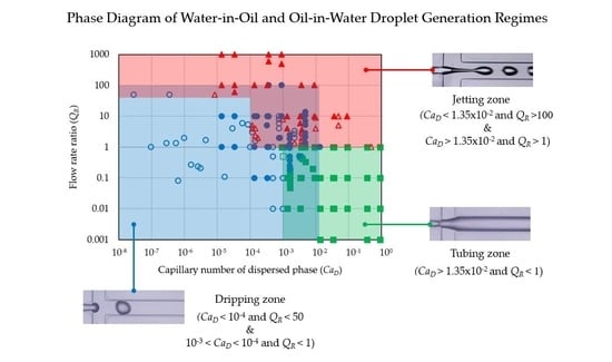
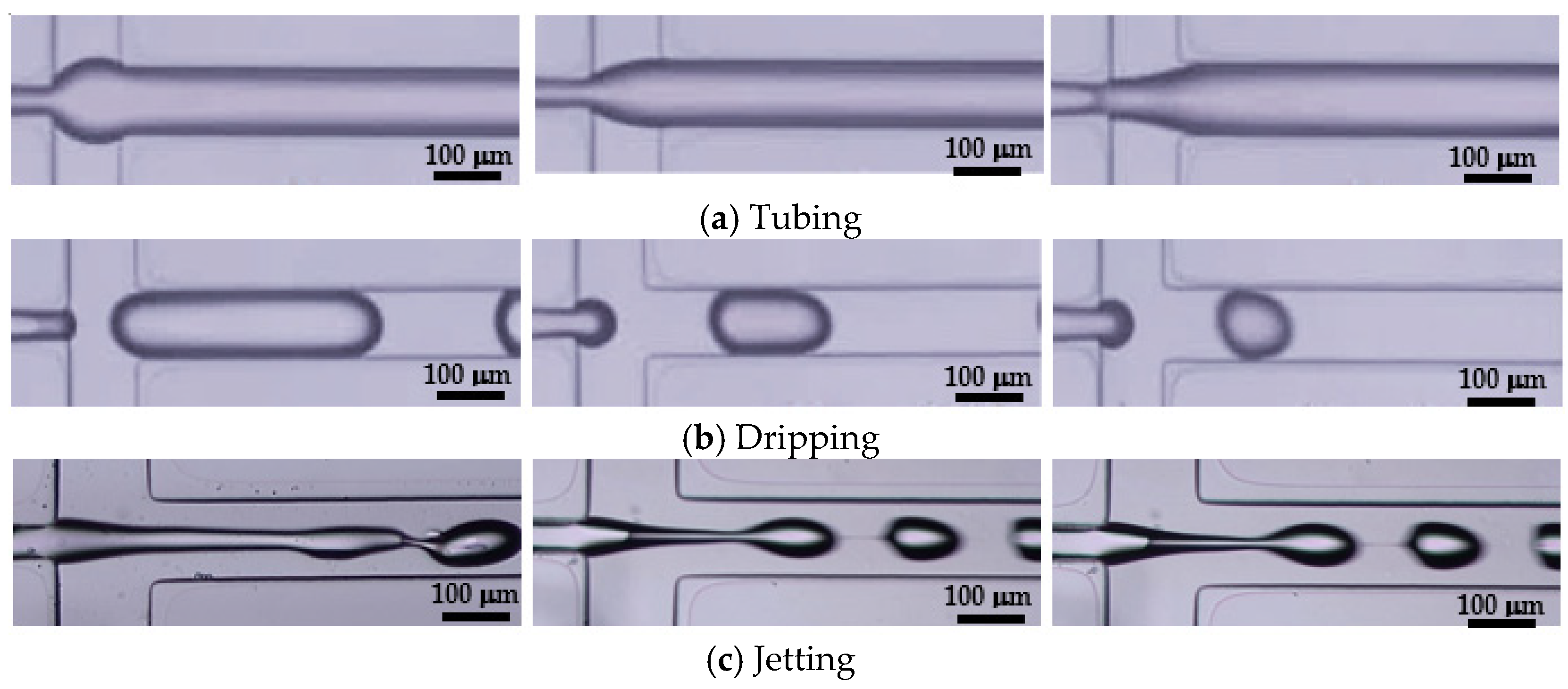
2.8. Droplet Generation Regime Identification and Classification

After a literature review regarding the classification of droplet generation regimes, it was found that there were different terminologies proposed for identifying similar droplet generation regimes from different research groups. For example, Cubaud and Mason [55] and Van Loo et al. [57] proposed the same terminology for the droplet generation regime named “dripping” but their droplet formations appear differently. Utada et al. [54] and Palagan et al. [58] demonstrated similar droplet formations but proposed different terminologies for this particular droplet generation regime, i.e., dripping and squeezing, respectively. Therefore, in the present work, the terminology is given to each droplet generation regime, which is clearly defined by its appearance and later will be used to classify the droplet formation obtained from the present experiment into a proper droplet generation regime.
The droplet formation can be classified into three different droplet generation regimes: tubing, dripping and jetting as shown in Figure 2. In the droplet generation regime “tubing”, the dispersed-phase fluid experiences a negligible fluid shear force from the continuous-phase fluid at the junction so that the droplet formation cannot take place and possibly the dispersed-phase fluid may slightly overflow into the continuous-phase channel at the junction. “Dripping” is the most desirable droplet generation regime for droplet formation where the wall shear force in the dispersed-phase channel and the fluid shear force in the continuous-phase fluid are balanced at the junction so that the droplet breakup occurs with a regular droplet size. In the droplet generation regime “jetting”, the droplet breakup takes place rather late downstream of the junction or never happens. In case the droplets can be formed in jetting, their sizes may possibly be irregular. For jetting, the dispersed-phase fluid is physically surrounded by the continuous-phase fluid and hence its appearance is like a jet.

3. Results and Discussion

For the experimental study in this work, it focuses on the occurrence and identification of three droplet generation regimes: tubing (T), dripping (D) and jetting (J), when water-in-oil and oil-in-water droplets are generated in microfluidic devices. The surface properties of micro-channels are hydrophobic and hydrophilic for the generation of water-in-oil and oil-in-water droplets, respectively. In some cases, the generation of water-in-oil and oil-in-water droplets is performed in the same microfluidic device where the surface property of the micro-channel is partially hydrophobic/hydrophilic. Droplets are generated by using the flow-focusing micro-channel where those three flow regimes are dependent on the input flow rates at the cross-junction so that the identification of those three flow regimes together with the specification of their corresponding operating conditions is essential. Physically, the flow-focusing micro-channel is governed by the hydrodynamic effect at the cross-junction due to the fluid shear stress of the continuous-phase flow and the wall shear stress acting on the dispersed-phase flow through the micro-channels of different surface properties. The dripping droplet generation regime is most effective for droplet break-up because there is the stability of the shear-stress balance at the cross-junction.

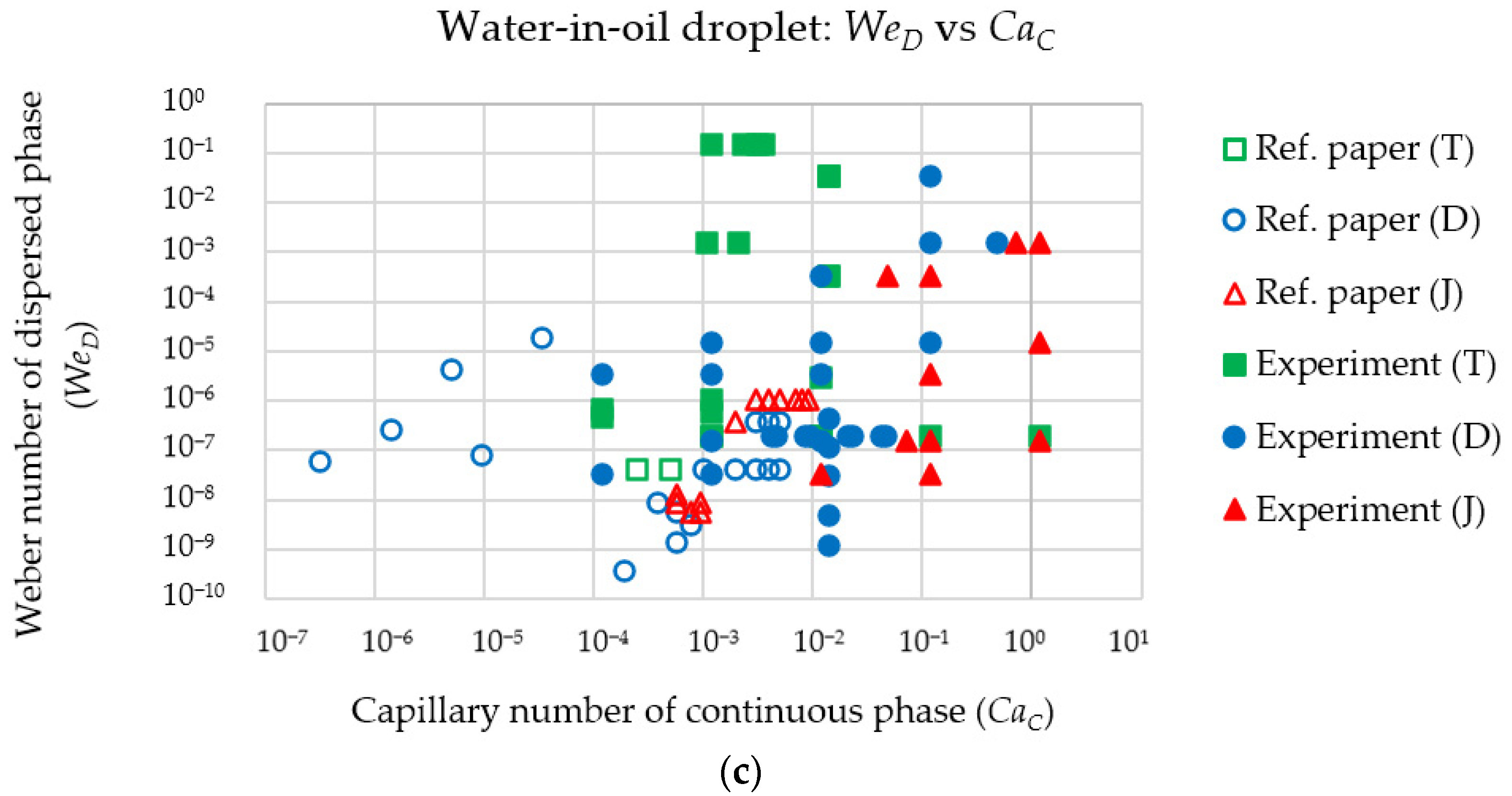
3.1. Water-in-Oil Droplet Generation

The experimental data used for the identification of droplet generation regimes in the case of water-in-oil droplets are collected from two different sources: (1) previous works and (2) present work. The experimental data of previous works were obtained from microfluidic devices in which the surface property of the micro-channel was hydrophobic and the DI water was used as the dispersed phase while various oils were used as the continuous phase. Table 3 is a summary of droplet generation regimes in the case of water-in-oil droplets obtained from previous works. The experimental data of the present work are obtained from two sets of microfluidic devices in which the surface properties of micro-channels with different cross-section sizes are hydrophobic, as summarized in Table 4, and partially hydrophobic/hydrophilic, as summarized in Table 5.
With various fluid properties and variations of micro-channel cross-section size and flow rate ratio, the identification of droplet generation regimes is attempted by using three different phase diagrams: (a) the flow-rate ratio (QR) versus the capillary number of the dispersed phase (CaD), (b) the capillary number of the continuous phase (CaC) versus the capillary number of the dispersed phase (CaD) and (c) the Weber number of the dispersed phase (WeD) versus the capillary number of the continuous phase (CaC), as displayed in Figure 3. It can be observed from these three-phase diagrams that three distinct droplet generation regimes (tubing, dripping and jetting) are clearly identified by using QR versus CaD, compared to other pairs of parameters (CaC versus CaD and WeD versus CaC). Therefore, the phase diagram of QR versus CaD is suitable for the specification of the operation condition for droplet generation. A suitable range of QR and CaD for the dripping droplet generation regime is (1) CaD < 10−4 and QR < 10 or (2) 10−4 < CaD < 10−3 and QR < 1. When CaD > 10−3 and QR < 1, the droplet generation regime becomes tubing. When QR > 60 together with CaD < 10−4, the droplet generation regime becomes jetting and, moreover, the droplet generation regime becomes jetting faster if CaD is increased.
The phase diagram of QR versus CaD is viable for the identification of a zone where droplets can be formed even though different oil properties are used in the micro-channel with various cross-section sizes and different surface properties. However, this conclusion is only valid for water-in-oil droplet generation so far since the majority of droplet generation in the literature was in favor of water-in-oil droplets. To further validate the phase diagram of QR versus CaD for the identification of the dripping droplet generation regime, the experiment of oil-in-water droplet generation is also performed in this work using the same microfluidic device as that for water-in-oil droplet generation.

3.2. Oil-in-Water Droplet Generation

Similar to water-in-oil droplet generation, the experimental data used for the classification of oil-in-water droplet generation regimes are collected from two different sources: (1) previous works and (2) present work. The experimental data of previous works were obtained from microfluidic devices in which the surface property of the micro-channel was hydrophilic and various oils were used as the dispersed phase while the DI water was used as the continuous phase. Table 6 is a summary of droplet generation regimes in the case of oil-in-water droplets obtained from previous works. The experimental data of the present work are obtained from two sets of microfluidic devices: (1) the surface property of the micro-channel is hydrophilic by using chemical coating as the surface modification method, as summarized in Table 7, and (2) the surface property of micro-channel is partially hydrophobic/hydrophilic by using permanent chemical coating as the surface modification method, as summarized in Table 8.
The classification of droplet generation regimes in the case of oil-in-water droplets is also attempted by using three different phase diagrams, such as the case of water-in-oil droplets: (a) the flow-rate ratio (QR) versus the capillary number of the dispersed phase (CaD), (b) the capillary number of the continuous phase (CaC) versus the capillary number of the dispersed phase (CaD) and (c) the Weber number of the dispersed phase (WeD) versus the capillary number of the continuous phase (CaC), as displayed in Figure 4. It is obvious that three-phase diagrams in Figure 4 can distinguish tubing, dripping and jetting droplet generation regimes more separately than the case of water-in-oil droplets, especially WeD versus CaC. However, these three-phase diagrams allocate different zoning and area sizes for tubing, dripping and jetting droplet generation regimes in such a biased way that CaD versus CaC and WeD versus CaC magnify only the tubing droplet generation regime. Therefore, QR versus CaD is a phase diagram of choice because comparable area sizes are allocated to tubing, dripping and jetting droplet generation regimes where tubing occurs when QR is less than or equal to 1 and CaD is greater than 10−3, jetting takes place when QR is greater than 10 and CaD is greater than 10−2, and dripping happens when QR is less than 10 and CaD is less than 10−3. The selection of QR versus CaD as a phase diagram of oil-in-water droplets can readily integrate the phase diagrams of oil-in-water and water-in-oil droplets together.

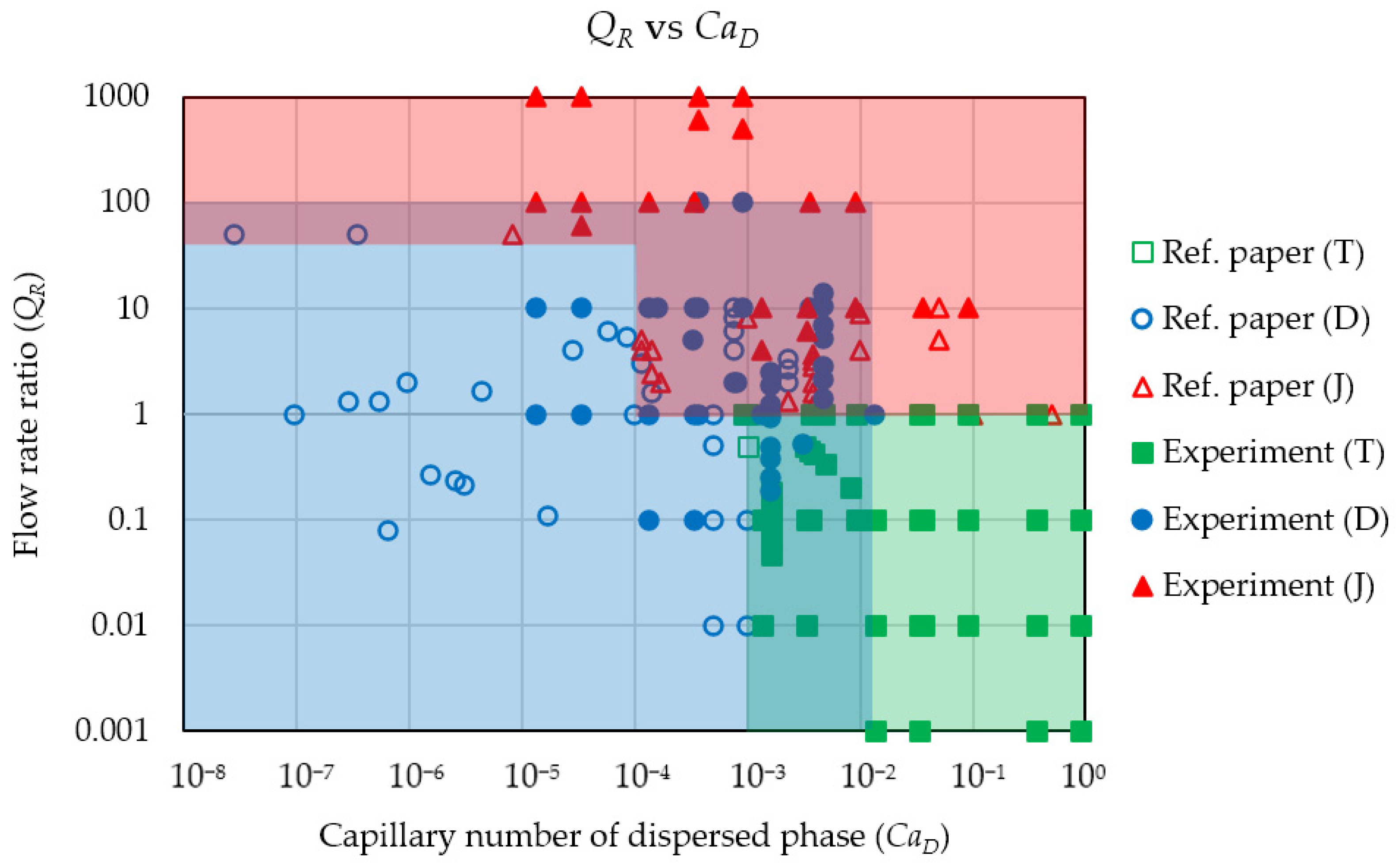
3.3. Droplet Generation Regimes

The phase diagram of QR versus CaD displayed in Figure 5 is used to classify the experimental data obtained from both water-in-oil droplet generation in Section 3.1 and oil-in-water droplet generation in Section 3.2 into three different droplet generation regimes: tubing (green zone), dripping (blue zone) and jetting (red zone). The classification by the phase diagram of QR versus CaD is quite vivid even though these experimental data from Section 3.1 and Section 3.2 are conducted in the micro-channels that have different surface properties. However, there are two noticeable overlapping zones that experience the transition from one droplet generation regime to another as well as mix the experimental data from both droplet generation regimes. The first overlapping zone is the transition between dripping and jetting. The second overlapping zone is the transition between dripping and tubing. There is no transition between tubing and jetting from our experimental point of view. If one aims to transition the droplet generation regime from tubing to jetting, while the flow rate of the dispersed phase is fixed, the flow rate of the continuous phase must be increased in order to transition from tubing to dripping as the first stage, and then the flow rate of the continuous phase must be increased further in order to finally transition from dripping to jetting. For the same result, the flow rate of the dispersed phase can be decreased while the flow rate of the continuous phase is fixed. The reverse transition from jetting to tubing can be achieved by decreasing the flow rate of the continuous phase (with a fixed flow rate of the dispersed phase) so that jetting is transitioned to dripping first and then dripping to tubing later. For the same result of the reverse transition, the flow rate of the dispersed phase can be increased while the flow rate of the continuous phase is fixed. Therefore, dripping seems to be an intermediate stage between tubing and jetting.
Using the phase diagram in Figure 5, the operating condition for successfully generating micro-droplets is a set of QR and CaD in the dripping zone (no matter if the micro-droplets needed are water-in-oil or oil-in-water). In addition, when the experimental data of the present work are plotted in this phase diagram, it is found that geometry, flow rate, type of droplet (W/O or O/W) and surface properties (hydrophobic, hydrophilic or partially hydrophobic/hydrophilic) have no effect on the droplet generation regimes. That means the micro-channel surface can be either hydrophobic or hydrophilic when one set of QR and CaD in the dripping zone is chosen to generate micro-droplets. At CaD = 10−3, the dripping zone is clearly separated from the tubing zones. Therefore, the dripping micro-droplets can be surely generated when (1) CaD < 10−4 and QR < 50 or (2) 10−3 < CaD < 10−4 and QR < 1. However, if CaD > 1.35 × 10⁻² and QR < 1, micro-droplets disappear and tubing takes place. Furthermore, micro-droplets can be replaced by jetting at two operating conditions: (1) CaD < 1.35 × 10⁻² and QR > 100 or (2) CaD > 1.35 × 10⁻² and QR > 1. Droplet generation is possible in the transition zone but unstable and unpredictable, so this zone should be avoided. The transition zone between dripping and jetting covers two areas: (1) the horizontal area where CaD < 10−4 and 50 < QR < 100 or (2) the vertical area where 10−4 < CaD < 1.35 × 10⁻² and 1 < QR < 100. The transition zone between dripping and tubing occupies an area of 10−3 < CaD < 1.35 × 10⁻² and QR < 1.
From the result of this study, it is found that the phase diagram of droplet generation regimes can be constructed using only two dimensionless parameters, i.e., QR and CaD, that will be used later to select the proper condition to generate droplets. Once the type of droplet is specified at one proper condition, the values of QR and CaD are obtained. The fluid properties must be specified at this point. The geometry of the device can then be calculated with the required flow rate. Finally, the micro-channel is designed in order to generate both water-in-oil and oil-in-water droplets using the flow structures of the flow-focusing channel with and without surface modification.

4. Conclusions

This research work proposes the phase diagram of QR versus CaD for the selection of a proper operating condition that can surely produce droplets. This phase diagram consists of three droplet generation regimes: tubing, dripping and jetting. Droplets cannot be formed in the tubing regime. It is clear from all of the considered phase diagrams that the parameters QR and CaD are the most suitable for classification compared to other parameters. In the phase diagram of QR versus CaD, the most appropriate operating condition for successfully generating micro-droplets is located in the dripping zone: (1) CaD < 10−4 and QR < 50 or (2) 10−3 < CaD < 10−4 and QR < 1.

Author Contributions

Conceptualization, A.K. and E.J.; methodology, A.K.; software, A.K.; validation, A.K.; formal analysis, A.K. and E.J.; investigation, A.K.; resources, E.J., W.S., P.P., N.A. and W.J.; data curation, A.K. and E.J.; writing—original draft preparation, A.K. and E.J.; writing—review and editing, A.K., E.J., N.K., M.C., W.S., P.P., C.P., N.A. and W.J.; visualization, A.K.; supervision, E.J. and W.J.; project administration, E.J. and W.J.; funding acquisition, A.K., E.J. and W.J. All authors have read and agreed to the published version of the manuscript.

Funding

This research was funded by National Science and Technology Development Agency (NSTDA), Thailand, grant number P-16-50098, and Faculty of Medicine, Siriraj Hospital, MU, Thailand, grant number r015936004.

Institutional Review Board Statement

Not applicable.

Informed Consent Statement

Not applicable.

Data Availability Statement

Not applicable.

Acknowledgments

The authors would like to gratefully thank the researchers of Thai Microelectronics Center (TMEC), National Electronics and Computer Technology Center (NECTEC), Thailand, and Department of Physiology, Faculty of Medicine, Siriraj Hospital, Mahidol University (MU), Thailand, for their helpful assistance. For the first author A.K., the PhD scholarship of Thailand Graduate Institute of Science and Technology (TGIST), NSTDA, Ministry of Higher Education, Research and Innovation (MHESI) [Grant No. TG-44-21-61-014D] and the tuition-fee-waiving scholarship of the Sirindhorn International Thai-German Graduate School of Engineering (TGGS), King Mongkut’s University of Technology North Bangkok (KMUTNB) are appreciably acknowledged.

Conflicts of Interest

The authors declare no conflict of interest.

References

  1. Vasiljevic, D.; Parojcic, J.; Primorac, M.; Vuleta, G. An investigation into the characteristics and drug release properties of multiple W/O/W emulsion systems containing low concentration of lipophilic polymeric emulsifier. Int. J. Pharm. 2006, 309, 171–177. [Google Scholar] [CrossRef] [PubMed]
  2. Gong, X.; Peng, S.; Wen, W.; Sheng, P.; Li, W. Design and fabrication of magnetically functionalized core/shell microspheres for smart drug delivery. Adv. Funct. Mater. 2009, 19, 292–297. [Google Scholar] [CrossRef]
  3. Brower, K.K.; Crumpton, C.C.; Klemm, S.; Cruz, B.; Kim, G.; Calhoun, S.G.K.; Nichols, L.; Fordyce, P.M. Double emulsion flow cytometry with high throughput single droplet isolation and nucleic acid recovery. Lab Chip 2020, 20, 2062–2074. [Google Scholar] [CrossRef] [PubMed]
  4. Hettiarachchi, K.; Kim, H.; Faris, G.W. Optical manipulation and control of real-time PCR in cell encapsulating microdroplets by IR laser. Microfluid. Nanofluid. 2012, 13, 967–975. [Google Scholar] [CrossRef]
  5. Liu, K.; Deng, Y.; Zhang, N.; Li, S.; Ding, H.; Guo, F.; Liu, W.; Guo, S.; Zhao, X.Z. Generation of disk-like hydrogel beads for cell encapsulation and manipulation using a droplet-based microfluidic device. Microfluid. Nanofluid. 2012, 13, 761–767. [Google Scholar] [CrossRef]
  6. Ding, Y.; Choo, J.; DeMello, A.J. From single-molecule detection to next-generation sequencing: Microfluidic droplets for high-throughput nucleic acid analysis. Microfluid. Nanofluid. 2017, 21, 58. [Google Scholar] [CrossRef]
  7. Guo, R.; Yang, C.G.; Xu, Z.R. A superposable double-gradient droplet array chip for preparation of PEGDA microspheres containing concentration-gradient drugs. Microfluid. Nanofluid. 2017, 21, 157. [Google Scholar] [CrossRef]
  8. Vaezi, Z.; Sedghi, M.; Ghorbani, M.; Shojaeilangari, S.; Allahverdi, A.; Manesh, H.N. Investigation of the programmed cell death by encapsulated cytoskeleton drug liposomes using a microfluidic platform. Microfluid. Nanofluid. 2020, 24, 48. [Google Scholar] [CrossRef]
  9. Wang, K.; Qin, K.; Wang, T.; Luo, G. Ultra-thin liquid film extraction based on a gas–liquid–liquid double emulsion in a microchannel device. RSC Adv. 2015, 5, 6470–6474. [Google Scholar] [CrossRef]
  10. Doonan, S.R.; Lin, M.; Lee, D.; Lee, J.; Bailey, R.C. C3PE: Counter-current continuous phase extraction for improved precision of in-droplet chemical reactions. Microfluid. Nanofluid. 2020, 24, 50. [Google Scholar] [CrossRef]
  11. Shum, H.C.; Lee, D.; Yoon, I.; Kodger, T.; Weitz, D.A. Double emulsion templated monodisperse phospholipid vesicles. Langmuir 2008, 24, 7651–7653. [Google Scholar] [CrossRef] [PubMed]
  12. Zheng, Y.; Yu, Z.; Parker, R.M.; Wu, Y.; Abell, C.; Scherman, O.A. Interfacial assembly of dendritic microcapsules with host–guest chemistry. Nat. Commun. 2014, 5, 5772. [Google Scholar] [CrossRef] [PubMed] [Green Version]
  13. Kim, B.; Jeon, T.Y.; Oh, Y.K.; Kim, S.H. Microfluidic production of semipermeable microcapsules by polymerization-induced phase separation. Langmuir 2015, 31, 6027–6034. [Google Scholar]
  14. Deshpande, S.; Caspi, Y.; Meijering, A.E.C.; Dekker, C. Octanol-assisted liposome assembly on chip. Nat. Commun. 2016, 7, 10447. [Google Scholar] [CrossRef] [Green Version]
  15. Lee, H.; Choi, C.H.; Abbaspourrad, A.; Wesner, C.; Caggioni, M.; Zhu, T.; Weitz, D.A. Encapsulation and enhanced retention of fragrance in polymer microcapsules. ACS Appl. Mater. 2016, 8, 4007–4013. [Google Scholar] [CrossRef]
  16. Wang, K.; Lu, Y.C.; Xu, J.H.; Tan, J.; Luo, G.S. Liquid–liquid micro-dispersion in a double-pore T-shaped microfluidic device. Microfluid. Nanofluid. 2009, 6, 557–564. [Google Scholar]
  17. Wang, K.; Lu, Y.C.; Xu, J.H.; Tan, J.; Luo, G.S. Generation of Micromonodispersed droplets and bubbles in the capillary embedded T-Junction microfluidic devices. AIChE J. 2011, 57, 2. [Google Scholar] [CrossRef]
  18. Wang, X.; Yong, Y.; Yang, C.; Mao, Z.S.; Li, D. Investigation on pressure drop characteristic and mass transfer performance of gas–liquid flow in micro-channels. Microfluid. Nanofluid. 2014, 16, 413–423. [Google Scholar]
  19. Seo, M.; Paquet, C.; Nie, Z.; Xua, S.; Kumacheva, E. Microfluidic consecutive flow-focusing droplet generators. Soft Matter 2007, 3, 986–992. [Google Scholar]
  20. Pannacci, N.; Bruus, H.; Bartolo, D.; Etchart, I.; Lockhart, T.; Hennequin, Y.; Willaime, H.; Tabeling, P. Equilibrium and Nonequilibrium States in Microfluidic Double Emulsions. PRL 2008, 101, 164502. [Google Scholar]
  21. Abate, A.R.; Thiele, J.; Weinhart, M.; Weitz, D.A. Patterning microfluidic device wettability using flow confinement. Lab Chip 2010, 10, 1774–1776. [Google Scholar] [CrossRef]
  22. Bauer, W.C.; Fischlechner, M.; Abell, C.; Huck, W.T.S. Hydrophilic PDMS microchannels for high-throughput formation of oil-in-water microdroplets and water-in-oil-in-water double emulsions. Lab Chip 2010, 10, 1814–1819. [Google Scholar] [CrossRef] [PubMed] [Green Version]
  23. Lin, H.H.; Chang, S.C.; Su, Y.C. On-demand double emulsification utilizing pneumatically actuated, selectively surface-modified PDMS micro-devices. Microfluid. Nanofluid. 2010, 9, 1091–1102. [Google Scholar] [CrossRef]
  24. Abate, A.R.; Thiele, J.; Weitz, D.A. One-step formation of multiple emulsions in microfluidics. Lab Chip 2011, 11, 253–258. [Google Scholar] [CrossRef] [PubMed]
  25. Deng, N.N.; Meng, Z.J.; Xie, R.; Ju, X.J.; Mou, C.L.; Wang, W.; Chu, L.Y. Simple and cheap microfluidic devices for the preparation of monodisperse emulsions. Lab Chip 2011, 11, 3963. [Google Scholar] [CrossRef] [PubMed]
  26. Thiele, J.; Seiffert, S. Double emulsions with controlled morphology by microgel scaffolding. Lab Chip 2011, 11, 3188. [Google Scholar] [CrossRef]
  27. Hwang, S.; Choi, C.H.; Lee, C.S. Regioselective surface modification of PDMS microfluidic device for the generation of monodisperse double emulsions. Macromol. Res. 2012, 20, 4. [Google Scholar] [CrossRef]
  28. Jankowski, P.; Ogonczyk, D.; Derzsi, L.; Lisowski, W.; Garstecki, P. Hydrophilic polycarbonate chips for generation of oil-in-water (O/W) and water-in-oil-in-water (W/O/W) emulsions. Microfluid. Nanofluid. 2013, 14, 767–774. [Google Scholar] [CrossRef] [Green Version]
  29. Wu, B.; Gong, H.Q.; Zhang, R. Maskless formation of chromatic-pattern barcodes in two-component microcapsules. Microfluid. Nanofluid. 2014, 16, 1069–1074. [Google Scholar] [CrossRef]
  30. Deng, N.N.; Mou, C.L.; Wang, W.; Ju, X.J.; Xie, R.; Chu, L.Y. Multiple emulsion formation from controllable drop pairs in microfluidics. Microfluid. Nanofluid. 2014, 17, 967–972. [Google Scholar] [CrossRef]
  31. Li, S.; Gong, X.; Mc Nally, C.S.; Zeng, M.; Gaule, T.; Anduix-Canto, C.; Kulak, A.N.; Bawazer, L.A.; McPherson, M.J.; Meldrum, F.C. Rapid preparation of highly reliable PDMS double emulsion microfluidic devices. RSC Adv. 2016, 6, 25927–25933. [Google Scholar] [CrossRef]
  32. Hirama, H.; Wada, S.; Shimamura, J.; Komazaki, Y.; Inoue, T.; Torii, T. Surface modification of a glass microchannel for the formation of multiple emulsion droplets. Microfluid. Nanofluid. 2017, 21, 91. [Google Scholar] [CrossRef]
  33. Cai, B.; Ji, T.T.; Wang, N.; Li, X.B.; He, R.X.; Liu, W.; Wang, G.; Zhao, X.Z.; Wang, L.; Wang, Z. A microfluidic platform utilizing anchored water-in-oil-in-water double emulsions to create a niche for analyzing single non-adherent cells. Lab Chip 2019, 19, 422–431. [Google Scholar] [CrossRef] [PubMed]
  34. Liao, Q.Q.; Zhao, S.K.; Cai, B.; He, R.X.; Rao, L.; Wu, Y.; Guo, S.S.; Liu, Q.Y.; Lui, W.; Zhao, X.Z. Biocompatible fabrication of cell-laden calcium alginate microbeads using microfluidic double flow-focusing device. Sens. Actuators A 2018, 279, 313–320. [Google Scholar] [CrossRef]
  35. Nawar, S.; Stolaroff, J.K.; Ye, C.; Wu, H.; Nguyen, D.T.; Xin, F.; Weitz, D.A. Parallelizable microfluidic dropmakers with multilayer geometry for the generation of double emulsions. Lab Chip 2020, 20, 147. [Google Scholar] [CrossRef] [PubMed]
  36. Nan, L.; Cao, Y.; Yuan, S.; Shum, H.C. Oil-mediated high-throughput generation and sorting of water-in-water droplets. Microsyst. Nanoeng. 2020, 6, 70. [Google Scholar] [CrossRef]
  37. Song, R.; Abbasi, M.S.; Lee, J. Fabrication of 3D printed modular microfluidic system for generating and manipulating complex emulsion droplets. Microfluid. Nanofluid. 2019, 23, 92. [Google Scholar] [CrossRef]
  38. Schmit, A.; Courbin, L.; Marquis, M.; Renard, D.; Panizza, P. A pendant drop method for the production of calibrated double emulsions and emulsion gels. RSC Adv. 2014, 4, 28504. [Google Scholar] [CrossRef]
  39. Si, T.; Feng, H.; Luo, X.; Xu, R.X. Formation of steady compound cone-jet modes and multilayered droplets in a tri-axial capillary flow focusing device. Microfluid. Nanofluid. 2015, 18, 967–977. [Google Scholar] [CrossRef]
  40. Wang, W.; Zhang, M.J.; Chu, L.Y. Microfluidic approach for encapsulation via double emulsions. Curr. Opin. Pharmacol. 2014, 18, 35–41. [Google Scholar] [CrossRef]
  41. Levenstein, M.A.; Bawazer, L.A.; Nally, C.S.; Marchant, W.J.; Gong, X.; Meldrum, F.C.; Kapur, N. A reproducible approach to the assembly of microcapillaries for double emulsion production. Microfluid. Nanofluid. 2016, 20, 143. [Google Scholar] [CrossRef] [Green Version]
  42. Che, Z.; Wong, T.N.; Nguyen, N.T. A simple method for the formation of water-in-oil-in-water (W/O/W) double emulsions. Microfluid. Nanofluid. 2017, 21, 8. [Google Scholar] [CrossRef] [Green Version]
  43. Hou, L.; Ren, Y.; Jia, Y.; Chen, X.; Deng, X.; Tang, Z.; Hu, Q.; Tao, Y.; Jiang, H. Osmolarity-controlled swelling behaviors of dual-cored double-emulsion drops. Microfluid. Nanofluid. 2017, 21, 60. [Google Scholar] [CrossRef]
  44. Michelona, M.; Huang, Y.; Torrec, L.G.; Weitz, D.A.; Cunha, R.L. Single-step microfluidic production of W/O/W double emulsions as templates for β-carotene-loaded giant liposomes formation. Chem. Eng. J. 2019, 366, 27–32. [Google Scholar] [CrossRef]
  45. Ngo, I.L.; Joo, S.W.; Byon, C. Effect of junction angle and viscosity ratio on droplet formation in microfluidic cross-junction. J. Fluids Eng. 2016, 138, 051202. [Google Scholar] [CrossRef]
  46. Gu, H.; Duits, M.H.G.; Mugele, F. Droplets formation and merging in two-phase flow microfluidics. Int. J. Mol. Sci. 2011, 12, 2572–2597. [Google Scholar] [CrossRef] [PubMed] [Green Version]
  47. Kim, T.J.; Hidrovo, C. Pressure and partial wetting effects on superhydrophobic friction reduction in microchannel flow. Phys. Fluids 2012, 24, 112003. [Google Scholar] [CrossRef] [Green Version]
  48. Woolford, B.; Maynes, D.; Webb, B.W. Liquid flow through microchannels with grooved walls under wetting and superhydrophobic conditions. Microfluid. Nanofluid. 2009, 7, 121–135. [Google Scholar] [CrossRef]
  49. Zhang, Y.; Ho, Y.; Chiu, Y.; Chan, H.F.; Chlebina, B.; Schuhmann, T.; You, L.; Leong, K.W. A programmable microenvironment for cellular studies via microfluidics-generated double emulsions. Biomaterials 2013, 34, 4564–4572. [Google Scholar] [CrossRef] [PubMed] [Green Version]
  50. Chiu, Y.; Chan, H.F.; Phua, K.L.; Zhang, Y.; Juul, S.; Knudsen, B.R.; Ho, Y.; Leong, K.W. Synthesis of fluorosurfactants for emulsion-based biological applications. ACS Nano 2014, 8, 3913–3920. [Google Scholar] [CrossRef] [PubMed]
  51. Dreyfus, R.; Tabeling, P.; Willaime, H. Ordered and disordered patterns in two-phase flows in microchannels. Phys. Rev. Lett. 2003, 90, 144505. [Google Scholar] [CrossRef] [PubMed] [Green Version]
  52. Glawdel, T.; Elbuken, C.; Ren, C.L. Droplet formation in microfluidic T-junction generators operating in the transitional regime. II. Model. Phys. Rev. 2012, 85, 016323. [Google Scholar] [CrossRef] [PubMed] [Green Version]
  53. Anna, S.L.; Mayer, H.C. Microscale tipstreaming in a microfluidic flow focusing device. Phys. Fluids 2006, 18, 121512. [Google Scholar] [CrossRef] [Green Version]
  54. Utada, A.S.; Nieves, A.F.; Stone, H.A.; Weitz, D.A. Dripping to jetting transitions in coflowing liquid streams. Phys. Rev. Lett. 2007, 99, 094502. [Google Scholar] [CrossRef] [PubMed]
  55. Cubaud, T. and Mason, T.G. Capillary threads and viscous droplets in square microchannels. Phys. Rev. Lett. 2008, 20, 053302. [Google Scholar]
  56. Derzsi, L.; Kasprzyk, M.; Plog, J.P.; Garstecki, P. Flow focusing with viscoelastic liquids. Phys. Rev. Lett. 2013, 25, 092001. [Google Scholar] [CrossRef] [Green Version]
  57. Loo, S.; Stoukatch, S.; Kraft, M.; Gilet, T. Droplet formation by squeezing in a microfluidic cross-junction. Microfluid. Nanofluid. 2016, 20, 146. [Google Scholar]
  58. Palogan, B.; Kumar, R.; Bhattacharya, S. Effect of surface coating on droplet generation in flow-focusing microchannels. Microfluid. Nanofluid. 2020, 24, 72. [Google Scholar] [CrossRef]
  59. Nie, Z.; Seo, M.; Xu, S.; Lewis, P.C.; Mok, M.; Kumacheva, E.; Whitesides, G.M.; Garstecki, P.; Stone, H.A. Emulsification in a microfluidic flow-focusing device: Effect of the viscosities of the liquids. Microfluid. Nanofluid. 2008, 5, 585–594. [Google Scholar] [CrossRef]
  60. Fu, T.; Wu, Y.; Ma, Y.; Li, H.Z. Droplet formation and breakup dynamics in microfluidic flow-focusing devices: From dripping to jetting. Chem. Eng. Sci. 2012, 84, 207–217. [Google Scholar] [CrossRef]
  61. Mastiani, M.; Seo, S.; Jimenez, S.M.; Petrozzi, N.; Kim, M.M. Flow regime mapping of aqueous two-phase system droplets in flow-focusing geometries. Colloids Surf. A Physicochem. Eng. Asp. 2017, 531, 111–120. [Google Scholar] [CrossRef]
  62. Wu, S.; Chen, J.; Lui, X.; Yao, F. Experimental study of droplet formation in the cross-junction. J. Dispers. Sci. Technol. 2020, 42, 1–8. [Google Scholar] [CrossRef]
  63. Liu, Z.h.; Chai, M.; Chen, X.; Hejazi, S.H.; Li, Y. Emulsification in a microfluidic flow-focusing device: Effect of the dispersed phase viscosity. Fuel 2021, 283, 119229. [Google Scholar] [CrossRef]
  64. Kalli, M.; Angeli, P. Effect of surfactants on drop formation flow patterns in a flow-focusing microchannel. Chem. Eng. Sci. 2022, 253, 117517. [Google Scholar] [CrossRef]
  65. Kamnerdsook, K.; Juntasaro, E.; Khemthongcharoen, N.; Chanasakulniyom, M.; Sripumkhai, W.; Pattamang, P.; Promptmas, C.; Atthi, N.; Jeamsaksiri, W. Formation of double emulsion micro-droplets in a microfluidic device using a partially hydrophilic-hydrophobic surface. RSC Adv. 2021, 11, 35653–35662. [Google Scholar] [CrossRef]
Figure 1. Schematic diagram of the microfluidic device for single-emulsion droplet generation with the flow-focusing micro-channel.
Colloids 07 00017 g001
Figure 2. Droplet generation regimes: (a) Tubing, (b) Dripping and (c) Jetting.
Colloids 07 00017 g002
Figure 3. Phase diagrams of droplet generation regimes: (a) QR vs. CaD, (b) CaC vs. CaD, and (c) WeD vs. CaC where T, D and J denote Tubing, Dripping and Jetting, respectively. (Concerning the data plotted in this phase diagram, the legend “Ref. paper” is identified in Table 3 while “Experiment” is identified in Table 4 and Table 5).
Colloids 07 00017 g003aColloids 07 00017 g003b
Figure 4. Phase diagrams of oil-in-water droplet generation regimes: (a) QR vs. CaD, (b) CaC vs. CaD, and (c) WeD vs. CaC where T, D and J denote Tubing, Dripping and Jetting, respectively. (Concerning the data plotted in this phase diagram, the legend “Ref. paper” is identified in Table 6 while “Experiment” is identified in Table 7 and Table 8).
Colloids 07 00017 g004
Figure 5. Phase diagram of water-in-oil and oil-in-water droplet generation regimes using QR versus CaD where T, D and J denote Tubing, Dripping and Jetting, respectively (Concerning the data plotted in this phase diagram, the legend “Ref. paper” is identified in Table 3 and Table 6 while “Experiment” is identified in Table 4, Table 5, Table 7 and Table 8).
Colloids 07 00017 g005
Table 1. Previous related works concerning the phase diagram of droplet generation.
Reference PaperDroplet TypeDispersed PhaseContinuous PhasePhase Diagram Parameter
x-Axisy-Axis
Anna and Mayer (2006) [53]W/ODI waterMineral oilCaDQR
Utada et al. [54]W/ODI waterPDMS oilCaCWeD
Cubaud and Mason (2008) [55]W/OGlycerol PDMS oilCaCCaD
Nie et al. (2008) [59]O/WTPGDA SDS CaDVD/VC
Fu et al. (2012) [60]O/WSilicone oilDI waterCaCWeD
Derzsi et al. (2012) [56]O/WSilicone oilGlycerol CaDCaC
Van Loo et al. (2016) [57]W/ODI waterSilicone oilCaDQR
Mastiani et al. (2017) [61]W/ODEG PEG solutionPDCaC
Palagan et al. (2020) [58]W/ODI waterSilicone oilCaDQR
Wu et al. (2020) [62]O/WSilicon oilPVA CaDCaC
Liu et al. (2021) [63]O/WMineral oilGlycerol QCQD
Kalli and Angeli (2022) [64]W/OGlycerolSilicone oilCaCCaD
Table 2. Detail of the droplet-based microfluidic device geometry (unit in µm), surface property and surface modification method.
Droplet TypeWDWCHSurface PropertySurface Modification Method
W/O25100100hydrophobicnot modified
50125100hydrophobicnot modified
50150100hydrophobicnot modified
25100100partiallypermanent chemical coating
202050partiallypermanent chemical coating
O/W25100100hydrophilicchemical coating
50125100hydrophilicchemical coating
50150100hydrophilicchemical coating
25100100partiallypermanent chemical coating
202050partiallypermanent chemical coating
Table 3. Summary of droplet generation regimes in the case of water-in-oil droplets obtained from previous works.
Reference PaperRegimeCaDCaCQRWeD
Bauer et al. (2010) [22]Dripping2.85 × 10−71.45 × 10−61.332.66 × 10−7
Abate et al. (2011) [24]Dripping3.04 × 10−63.40 × 10−50.211.89 × 10−5
Li et al. (2016) [31]Dripping2.33 × 10−111.21 × 10−91.672.61 × 10−12
Cai et al. (2019) [33]Dripping9.50 × 10−83.20 × 10−71.005.91 × 10−8
Liao et al. (2018) [34]Dripping5.42 × 10−79.66 × 10−61.338.09 × 10−8
Nan et al. (2020) [36]Dripping1.57 × 10−65.08 × 10−60.274.21 × 10−6
Van Loo et al. (2016) [57]Dripping5.00 × 10−4n/a0.01n/a
Dripping5.00 × 10−4n/a0.10n/a
Dripping5.00 × 10−4n/a0.50n/a
Dripping1.00 × 10−4n/a1.00n/a
Jetting1.00 × 10−3n/a8.00n/a
Jetting5.00 × 10−2n/a5.00n/a
Jetting1.00 × 10−2n/a4.00n/a
Jetting5.00 × 10−1n/a1.00n/a
Palagan et al. (2020) [58]Dripping1.00 × 10−3n/a0.01n/a
Dripping1.00 × 10−3n/a0.10n/a
Dripping5.00 × 10−4n/a1.00n/a
Jetting5.00 × 10−2n/a10.00n/a
Jetting1.00 × 10−2n/a9.00n/a
Jetting1.00 × 10−1n/a1.00n/a
Liu et al. (2021) [63]Dripping2.86 × 10−51.93 × 10−44.003.58 × 10−10
Dripping5.72 × 10−55.79 × 10−46.001.43 × 10−10
Dripping8.59 × 10−57.72 × 10−45.333.22 × 10−9
Dripping1.14 × 10−45.79 × 10−43.005.72 × 10−9
Dripping1.43 × 10−43.86 × 10−41.608.94 × 10−9
Jetting1.14 × 10−47.72 × 10−44.005.72 × 10−9
Jetting1.14 × 10−49.65 × 10−45.005.72 × 10−9
Jetting1.43 × 10−45.79 × 10−42.408.94 × 10−9
Jetting1.43 × 10−49.65 × 10−44.008.94 × 10−9
Jetting1.72 × 10−45.79 × 10−42.001.29 × 10−8
Kalli and Angeli (2022) [64]Tubing1.02 × 10−32.51 × 10−40.504.19 × 10−8
Tubing1.01 × 10−34.96 × 10−41.004.19 × 10−8
Dripping7.63 × 10−41.00 × 10−32.004.19 × 10−8
Dripping7.63 × 10−42.00 × 10−34.004.19 × 10−8
Dripping7.63 × 10−43.01 × 10−36.004.19 × 10−8
Dripping7.63 × 10−44.01 × 10−38.004.19 × 10−8
Dripping7.63 × 10−45.01 × 10−310.004.19 × 10−8
Dripping2.29 × 10−33.01 × 10−32.003.77 × 10−7
Dripping2.29 × 10−34.01 × 10−32.673.77 × 10−7
Dripping2.29 × 10−35.01 × 10−33.333.77 × 10−7
Jetting2.29 × 10−32.00 × 10−31.333.77 × 10−7
Jetting3.81 × 10−33.01 × 10−31.201.05 × 10−6
Jetting3.81 × 10−34.01 × 10−31.601.05 × 10−6
Jetting3.81 × 10−35.01 × 10−32.001.05 × 10−6
Jetting3.81 × 10−37.02 × 10−32.801.05 × 10−6
Jetting3.81 × 10−38.02 × 10−33.201.05 × 10−6
Jetting3.81 × 10−39.02 × 10−33.601.05 × 10−6
Table 4. Summary of droplet generation regimes in the case of water-in-oil droplets of present work using hydrophobic micro-channels with three different cross-section sizes where WD, WC and H are micro-channel width of the dispersed phase, micro-channel width of the continuous phase and micro-channel height, respectively.
DeviceRegimeCaDCaCQRWeD
WD25WC100H100Dripping1.63 × 10−41.43 × 10−210.001.18 × 10−9
Dripping3.25 × 10−41.43 × 10−25.004.74 × 10−9
Dripping8.13 × 10−41.43 × 10−22.002.96 × 10−8
Dripping1.63 × 10−31.43 × 10−21.001.18 × 10−7
Dripping3.14 × 10−31.43 × 10−20.524.43 × 10−7
Tubing3.25 × 10−31.43 × 10−20.504.74 × 10−7
Tubing3.58 × 10−31.43 × 10−20.455.73 × 10−3
Tubing3.90 × 10−31.43 × 10−20.426.82 × 10−7
Tubing4.88 × 10−31.43 × 10−20.331.07 × 10−6
Tubing8.13 × 10−31.43 × 10−20.202.96 × 10−6
WD50WC125H100Tubing1.63 × 10−31.09 × 10−30.051.97 × 10−7
Tubing1.63 × 10−32.12 × 10−30.091.97 × 10−7
Tubing1.63 × 10−33.19 × 10−30.141.97 × 10−7
Dripping1.63 × 10−34.28 × 10−30.191.97 × 10−7
Dripping1.63 × 10−38.54 × 10−30.371.97 × 10−7
Dripping1.63 × 10−32.14 × 10−20.931.97 × 10−7
Dripping1.63 × 10−34.27 × 10−21.861.97 × 10−7
WD50WC150H100Tubing1.63 × 10−31.19 × 10−30.061.97 × 10−7
Tubing1.63 × 10−32.34 × 10−30.121.97 × 10−7
Tubing1.63 × 10−33.56 × 10−30.191.97 × 10−7
Dripping1.63 × 10−34.73 × 10−30.251.97 × 10−7
Dripping1.63 × 10−39.46 × 10−30.501.97 × 10−7
Dripping1.63 × 10−32.36 × 10−21.241.97 × 10−7
Dripping1.63 × 10−34.72 × 10−22.471.97 × 10−7
Table 5. Summary of droplet generation regimes in the case of water-in-oil droplets of present work using partially hydrophobic/hydrophilic micro-channels with two different cross-section sizes where WD, WC and H are micro-channel widths of the dispersed phase, micro-channel width of the continuous phase and micro-channel height respectively.
DeviceRegimeCaDCaCQRWeD
WD25WC100H100Dripping1.35 × 10−51.19 × 10−41.003.37 × 10−8
Dripping1.35 × 10−51.19 × 10−310.003.37 × 10−8
Jetting1.35 × 10−51.19 × 10−2100.003.37 × 10−8
Jetting1.35 × 10−51.19 × 10−11000.003.37 × 10−8
Dripping1.35 × 10−41.19 × 10−40.103.37 × 10−6
Dripping1.35 × 10−41.19 × 10−31.003.37 × 10−6
Dripping1.35 × 10−41.19 × 10−210.003.37 × 10−6
Jetting1.35 × 10−41.19 × 10−1100.003.37 × 10−6
Tubing1.35 × 10−31.19 × 10−40.013.37 × 10−4
Tubing1.35 × 10−31.19 × 10−30.103.37 × 10−4
Dripping1.35 × 10−31.19 × 10−21.003.37 × 10−4
Jetting1.35 × 10−34.78 × 10−24.003.37 × 10−4
Jetting1.35 × 10−31.19 × 10−110.003.37 × 10−4
Tubing1.35 × 10−21.19 × 10−40.003.37 × 10−2
Tubing1.35 × 10−21.19 × 10−30.013.37 × 10−2
Tubing1.35 × 10−21.19 × 10−20.103.37 × 10−2
Dripping1.35 × 10−21.19 × 10−11.003.37 × 10−2
WD20WC20H50Dripping3.39 × 10−51.19 × 10−31.001.51 × 10−7
Dripping3.39 × 10−51.19 × 10−210.001.51 × 10−7
Jetting3.39 × 10−57.16 × 10−260.001.51 × 10−7
Jetting3.39 × 10−51.19 × 10−1100.001.51 × 10−7
Jetting3.39 × 10−51.19 × 1001000.001.51 × 10−7
Dripping3.39 × 10−41.19 × 10−30.101.51 × 10−5
Dripping3.39 × 10−41.19 × 10−21.001.51 × 10−5
Dripping3.39 × 10−41.19 × 10−110.001.51 × 10−5
Jetting3.39 × 10−41.19 × 100100.001.51 × 10−5
Tubing3.39 × 10−31.19 × 10−30.011.51 × 10−3
Tubing3.39 × 10−31.19 × 10−20.101.51 × 10−3
Dripping3.39 × 10−31.19 × 10−11.001.51 × 10−3
Dripping3.39 × 10−34.78 × 10−14.001.51 × 10−3
Jetting3.39 × 10−37.16 × 10−16.001.51 × 10−3
Jetting3.39 × 10−31.19 × 10010.001.51 × 10−3
Tubing3.39 × 10−21.19 × 10−30.0011.51 × 10−1
Tubing3.39 × 10−21.19 × 10−20.011.51 × 10−1
Tubing3.39 × 10−21.19 × 10−10.101.51 × 10−1
Tubing3.39 × 10−21.19 × 1001.001.51 × 10−1
Table 6. Summary of droplet generation regimes in the case of oil-in-water droplets obtained from previous works.
Reference PaperRegimeCaDCaCQRWeD
Bauer et al. (2010) [22]Dripping9.60 × 10−71.42 × 10−72.006.05 × 10−7
Abate et al. (2011) [24]Dripping2.54 × 10−67.12 × 10−70.233.09 × 10−7
Li et al. (2016) [31]Dripping4.35 × 10−61.90 × 10−61.673.63 × 10−6
Cai et al. (2019) [33]Dripping1.69 × 10−52.94 × 10−60.114.71 × 10−8
Liao et al. (2018) [34]Dripping1.90 × 10−91.30 × 10−100.162.61 × 10−12
Nan et al. (2020) [36]Dripping6.40 × 10−72.37 × 10−60.082.02 × 10−7
Nie et al. (2008) [59]Dripping2.78 × 10−87.94 × 10−850.001.38 × 10−15
Dripping3.47 × 10−79.92 × 10−750.002.15 × 10−13
Jetting8.33 × 10−62.38 × 10−550.001.24 × 10−10
Fu et al. (2012) [60]Tubingn/a2.00 × 10−4n/a1.00 × 10−7
Tubingn/a2.00 × 10−4n/a1.00 × 10−6
Tubingn/a2.00 × 10−4n/a1.00 × 10−5
Tubingn/a2.00 × 10−4n/a1.00 × 10−4
Tubingn/a2.00 × 10−4n/a1.00 × 10−3
Drippingn/a1.00 × 10−3n/a1.00 × 10−7
Drippingn/a1.00 × 10−3n/a1.00 × 10−5
Drippingn/a1.00 × 10−3n/a1.00 × 10−3
Drippingn/a1.00 × 10−2n/a1.00 × 10−4
Drippingn/a1.00 × 10−2n/a1.00 × 10−2
Jettingn/a4.00 × 10−2n/a1.00 × 10−3
Jettingn/a4.00 × 10−2n/a1.00 × 10−2
Jettingn/a4.00 × 10−2n/a1.00 × 10−1
Wu et al. (2020) [62]Tubing2.00 × 10−41.00 × 10⁻³n/an/a
Tubing1.00 × 10−45.00 × 10⁻⁴n/an/a
Tubing7.00 × 10−43.00 × 10⁻⁴n/an/a
Tubing5.00 × 10−42.00 × 10⁻⁴n/an/a
Tubing4.00 × 10−41.00 × 10⁻⁴n/an/a
Dripping1.00 × 10−52.00 × 10⁻³n/an/a
Dripping2.00 × 10−54.00 × 10⁻³n/an/a
Dripping3.00 × 10−55.00 × 10⁻³n/an/a
Dripping5.00 × 10−57.00 × 10⁻³n/an/a
Dripping1.00 × 10−47.00 × 10⁻³n/an/a
Table 7. Summary of droplet generation regimes in the case of oil-in-water droplets of present work using hydrophilic micro-channels with two different cross-section sizes where WD, WC and H are micro-channel widths of the dispersed phase, micro-channel width of the continuous phase and micro-channel height, respectively.
DeviceRegimeCaDCaCQRWeD
WD50WC125H100Tubing4.78 × 10−35.42 × 10−51.004.12 × 10−8
Dripping4.78 × 10−31.14 × 10−42.104.12 × 10−8
Dripping4.78 × 10−32.82 × 10−45.204.12 × 10−8
Dripping4.78 × 10−35.69 × 10−410.504.12 × 10−8
WD50WC150H100Tubing4.78 × 10−36.32 × 10−51.404.12 × 10−8
Dripping4.78 × 10−31.26 × 10−42.804.12 × 10−8
Dripping4.78 × 10−33.16 × 10−47.004.12 × 10−8
Dripping4.78 × 10−36.28 × 10−413.904.12 × 10−8
Table 8. Summary of droplet generation regimes in the case of oil-in-water droplets of present work using partially hydrophobic/hydrophilic micro-channels with two different cross-section sizes where WD, WC and H are micro-channel widths of the dispersed phase, micro-channel width of the continuous phase and micro-channel height respectively.
DeviceRegimeCaDCaCQRWeD
WD25WC100H100Tubing3.65 × 10−42.16 × 10−51.003.01 × 10−8
Dripping3.65 × 10−42.16 × 10−410.003.01 × 10−8
Dripping3.65 × 10−42.16 × 10−3100.003.01 × 10−8
Jetting3.65 × 10−41.29 × 10−2600.003.01 × 10−8
Jetting3.65 × 10−42.16 × 10−21000.003.01 × 10−8
Tubing3.65 × 10−32.16 × 10−50.103.01 × 10−6
Tubing3.65 × 10−32.16 × 10−41.003.01 × 10−6
Dripping3.65 × 10−32.16 × 10−310.003.01 × 10−6
Jetting3.65 × 10−32.16 × 10−2100.003.01 × 10−6
Tubing3.65 × 10−22.16 × 10−50.013.01 × 10−4
Tubing3.65 × 10−22.16 × 10−40.103.01 × 10−4
Tubing3.65 × 10−22.16 × 10−31.003.01 × 10−4
Jetting3.65 × 10−22.16 × 10−210.003.01 × 10−4
Tubing3.65 × 10−12.16 × 10−50.003.01 × 10−2
Tubing3.65 × 10−12.16 × 10−40.013.01 × 10−2
Tubing3.65 × 10−12.16 × 10−30.103.01 × 10−2
Tubing3.65 × 10−12.16 × 10−21.003.01 × 10−2
WD20WC20H50Tubing9.13 × 10−42.16 × 10−41.001.34 × 10−7
Dripping9.13 × 10−42.16 × 10−310.001.34 × 10−7
Dripping9.13 × 10−42.16 × 10−2100.001.34 × 10−7
Jetting9.13 × 10−41.08 × 10−1500.001.34 × 10−7
Jetting9.13 × 10−42.16 × 10−11000.001.34 × 10−7
Tubing9.13 × 10−32.16 × 10−40.101.34 × 10−5
Tubing9.13 × 10−32.16 × 10−31.001.34 × 10−5
Jetting9.13 × 10−32.16 × 10−210.001.34 × 10−5
Jetting9.13 × 10−32.16 × 10−1100.001.34 × 10−5
Tubing9.13 × 10−22.16 × 10−40.011.34 × 10−3
Tubing9.13 × 10−22.16 × 10−30.101.34 × 10−3
Tubing9.13 × 10−22.16 × 10−21.001.34 × 10−3
Jetting9.13 × 10−22.16 × 10−110.001.34 × 10−3
Tubing9.13 × 10−12.16 × 10−40.0011.34 × 10−1
Tubing9.13 × 10−12.16 × 10−30.011.34 × 10−1
Tubing9.13 × 10−12.16 × 10−20.101.34 × 10−1
Disclaimer/Publisher’s Note: The statements, opinions and data contained in all publications are solely those of the individual author(s) and contributor(s) and not of MDPI and/or the editor(s). MDPI and/or the editor(s) disclaim responsibility for any injury to people or property resulting from any ideas, methods, instructions or products referred to in the content.

