Article

Simple Mixed-Acid-Treated Carbon Fiber Electrodes with Oxygen-Containing Functional Groups for Flexible Supercapacitors

1
Key Laboratory for Liquid-Solid Structural Evolution and Processing of Materials (Ministry of Education), State Key Laboratory of Crystal Materials, Shandong University, Jinan 250061, China
2
Carbon Fiber Engineering Research Center, School of Materials Science and Engineering, Shandong University, Jinan 250061, China
*
Authors to whom correspondence should be addressed.
J. Compos. Sci. 2023, 7(6), 231; https://doi.org/10.3390/jcs7060231
Submission received: 1 May 2023 / Revised: 26 May 2023 / Accepted: 2 June 2023 / Published: 5 June 2023
(This article belongs to the Special Issue Composites for Energy Storage Applications, Volume II)

Abstract

:
Flexible supercapacitors are demanded for energy storage of wearable electronics. In this paper, a simple strategy for preparing flexible carbon fibers (CFs) with good energy storage capacity using a mixed acid treatment process is reported. When the volume ratio of concentrated sulfuric acid to concentrated nitric acid is 3:1, the carbon fiber electrodes have the best electrochemical performance with a high capacitance of 27.83 F g−1 at 15 mA g−1 and extremely high capacitance retention of 79.9% after 500 cycles at 100 mA g−1. Furthermore, their energy density can reach 3.86 Wh kg−1 with a power density of 7.5 W kg−1. Such an excellent electrochemical performance of carbon fiber electrodes is attributed to their surface rich oxygen-containing functional groups, rough surface, and a certain number of graphene quantum dots (GQDs). Importantly, the all-solid-state flexible supercapacitor performs excellent bending stability performance with a capacitance retention of almost 100% after 500 times of bending at 180°, showing good prospects and applications in the field of flexible energy storage devices.

1. Introduction

With the development and application of flexible electronic technology, there is a growing demand for flexible energy storage devices [1,2,3]. At present, flexible energy storage devices mainly include flexible supercapacitors and flexible lithium-ion batteries [4,5,6,7,8]. Among them, flexible-fiber supercapacitors have attracted extensive attention because of their high power density, rapid charge–discharge rate, good flexibility, and braidability [7,9,10,11,12]. Carbon materials have been widely used as electrode materials for flexible supercapacitors because of their excellent conductivity, good corrosion resistance, stability, and excellent mechanical properties [7,13,14]. Common carbon-based electrode materials mainly include carbon fibers [15,16], carbon nanotubes [17,18], and graphene [11,19,20]. Among them, carbon fibers have outstanding mechanical properties, including high tensile strength and modulus, excellent conductivity, and chemical stability [21,22]. Compared with graphene and carbon nanotubes, carbon fibers’ cost is lower, and their process route is relatively simple and mature. In addition, carbon fibers can also be directly assembled into fibrous supercapacitors. Therefore, carbon fibers have great advantages as electrode material for flexible fibrous capacitors.
However, due to their compact structure and small specific surface area, the electrochemical performance of carbon fibers is poor when they are directly used as electrode materials [15,23]. The activation [16,24,25,26] and surface treatment methods [27] are usually used to improve their specific surface area, followed by electrochemical properties. For example, Zhang et al. [26] prepared the specific surface area of activated carbon fibers, which reached 1222 m2 g−1 with an activation temperature of 550 °C and showed good electrochemical and cyclic properties. However, during the activation process, a large number of pore structures appeared on the interior and surface of the fibers, affecting the conductivity and mechanical properties of the fibers. Therefore, the fibers cannot be directly woven into a capacitor, which limits their application in flexible capacitors. Carbon fibers can also be used as carriers for other active materials. By growing materials with high activity on their surface (such as conductive polymers, transition metal oxides, etc.), the electrochemical activity of the electrodes can be improved [28,29,30]. Yuan et al. [31] deposited a layer of MnO2 nanorods on the surface of carbon fibers using an electrochemical deposition method to obtain composite electrodes. Due to the addition of active materials, the electrochemical performance of the composite electrodes was significantly improved. However, the active material of the assembled flexible supercapacitor easily peeled off the matrix under the conditions of mechanical deformation such as bending and stretching, which affected the electrochemical performance of the capacitor. The deposition methods were then optimized to improve the combination between the active material and the matrix to avoid the active material falling off the matrix [32,33,34]. However, the active material was always inevitably separated from the matrix under the conditions of long-term mechanical deformation. The direct use of a flexible conductive substrate as an energy storage device is an effective way to solve this problem. At present, most researchers are committed to improving the energy storage capacity of capacitors by adding active materials, while there are few studies on using the matrix both as a conductive matrix and as active materials.
In this study, carbon fibers were treated with an ultrasonic hydrothermal treatment in mixed acid solutions with different volume ratios. The electrochemical performance of the carbon fibers treated with mixed acid was significantly improved. The fibers’ electrodes showed high specific capacitance with 27.83 F g−1 at 15 mA g−1 and excellent stable cycle performance with capacitance retention of 79.9% after 500 cycles at 100 mA g−1. The fiber electrodes were assembled into an all-solid flexible-fiber supercapacitor with H2SO4/PVA as the solid electrolyte. When the current density was 5 mA g−1, the mass specific capacitance was 3.8 F g−1. After 1000 cycles of testing, the capacitance retention was 73.05%, showing excellent stability. The capacitor also showed an excellent bending stability with a capacitance retention of almost 100% after bending 180° 500 times. In practical application, the capacitor continuously lit an LED bulb for 12 min after charging under constant voltage. Our results demonstrate important practical significance for the application of a flexible matrix in the field of energy storage and flexible equipment.

2. Materials and Methods

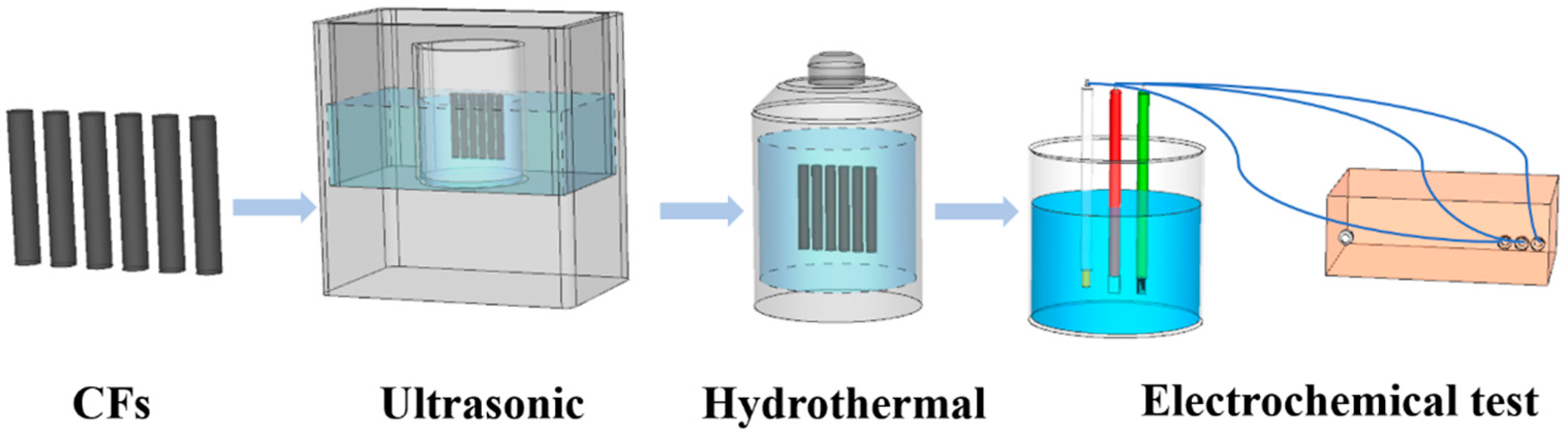
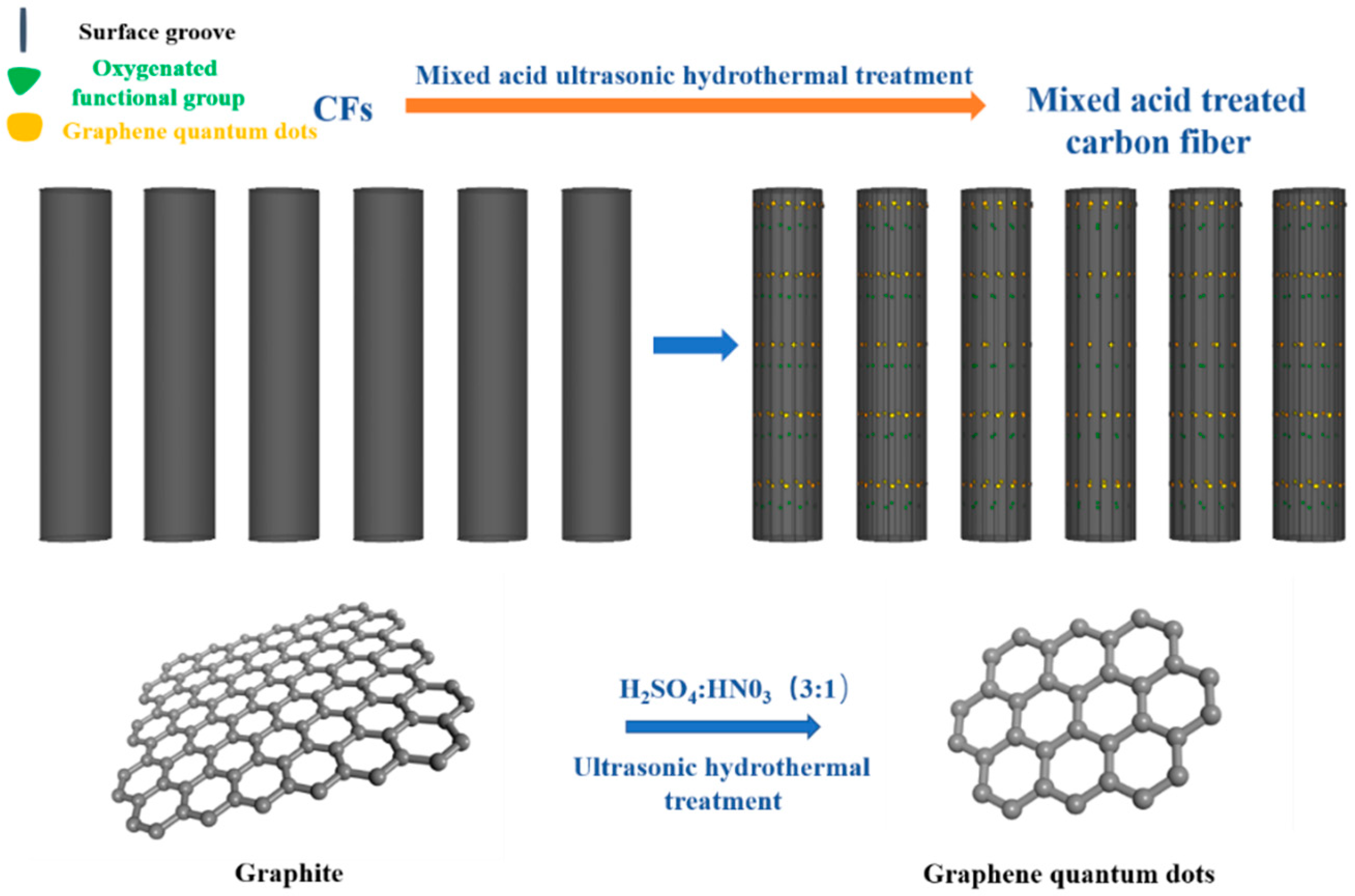
2.1. Ultrasonic Hydrothermal Treatment of Carbon Fibers

Carbon fibers (T700, Toray, Tokyo, Japan) were ultrasonically cleaned in acetone, ethanol, and deionized water for 30 min, respectively. After ultrasonic cleaning, CFs were dried in an oven at 60 °C for 30 min. We prepared a certain volume ratio of concentrated H2SO4 (18 M) and concentrated HNO3 (15 M) mixed acid solution at room temperature, and then we put the CFs into the mixed acid solution for an ultrasound for 2 h. After the ultrasound, the CFs were put into the reaction kettle for hydrothermal reaction. The hydrothermal reaction time was 30 min with a hydrothermal temperature of 100 °C. The reaction kettle was opened to take out the CFs after the hydrothermal reaction, and the CFs were washed repeatedly with deionized water. Finally, we put the CFs into an oven at 60 °C for drying for 6 h. The schematic diagram for the process is shown in Figure 1.
CF-NxSx represents the carbon fibers obtained after mixed acid treatment in different volume ratios. For example, CF-N1S1 represents the carbon fibers prepared after ultrasonic hydrothermal treatment when the volume ratio of concentrated H2SO4 to concentrated HNO3 was 1:1.
The set mixed acid volume is shown in Table 1.

2.2. Preparation of the All-Solid-State Flexible Supercapacitor

An amount of 5 g of concentrated H2SO4 was added to 50 g deionized water and stirred evenly. Then, 5 g PVA powder (Polyvinyl alcohol, Aladdin Reagent Co., Ltd., Shanghai, China) was added to a three-necked flask, and the prepared H2SO4 solution was added to the three-necked flask. Then, it was put into a water bath pot and heated at 90 °C while being stirred for 1 h. After heating, the H2SO4/PVA gel electrolyte was successfully prepared.
The carbon fibers were cut into 6 cm short fibers. We put one end of the carbon fibers into the H2SO4/PVA gel electrolyte for 30 s and then cooled it at room temperature for 1 min. The above steps were repeated 3 times, and then the carbon fibers coated with electrolytes were put into the culture dish and dried at room temperature for 3 h. After cooling, two fiber electrodes were intertwined to form an all-solid-state flexible-fiber supercapacitor.

2.3. Test Characterization

The surface morphology of carbon fibers was characterized using a thermal field emission scanning electron microscope (Hitachi, SU-70, Tokyo, Japan). The micro morphology, crystal structure, and crystal plane spacing of carbon fibers were measured and analyzed using a transmission electron microscope (Electronics Co., Ltd., Kagawa, Japan, JEM-2100). The phase composition and surface structure of carbon fibers were characterized using X-ray diffraction (Dandong, China, TD-3700) and Raman spectroscopy (HORIRA Jobin Yvon, Glasgow, Scotland, LabRaAM-HR800). The surface functional groups and elemental compositions of carbon fibers were measured and analyzed using an Infrared spectrometer (Bruker, Leipzig, Germany, TENSOR II) and X-ray diffractometer (Rigaku D/max-RC, Tokyo, Japan).

2.4. Electrochemical Test

The single electrode electrochemical test adopted the three-electrode system under the electrochemical workstation (Shanghai Chenhua Instrument Co., Ltd., Shanghai, China), in which the prepared carbon fibers were used as the working electrodes, a platinum electrode was used as the counter electrode, and a saturated calomel electrode was used as the reference electrode. The electrolyte was 1M H2SO4 solution. The voltage window was set to 0–1.0 V.
The electrochemical test of the all-solid-state flexible-fiber supercapacitor adopted a two-electrode system to test, in which the working electrode was connected to the positive electrode of the capacitor, and the counter electrode and reference electrode were connected to the negative electrode of the capacitor. The electrolyte was H2SO4/PVA gel electrolyte, and the voltage window of the capacitor was set to 0–1.0 V.
The cyclic voltammetry (CV), the galvanostatic charge–discharge (GCD) measurements, and the electrochemical impedance spectroscopy (EIS) were measured using a CHI660E electrochemical workstation (Shanghai Chenhua Instrument Co., Ltd., Shanghai, China). EIS was carried out using an open-circuit potential and frequency ranges from 0.01 Hz to 100 kHz.

3. Results and Discussion

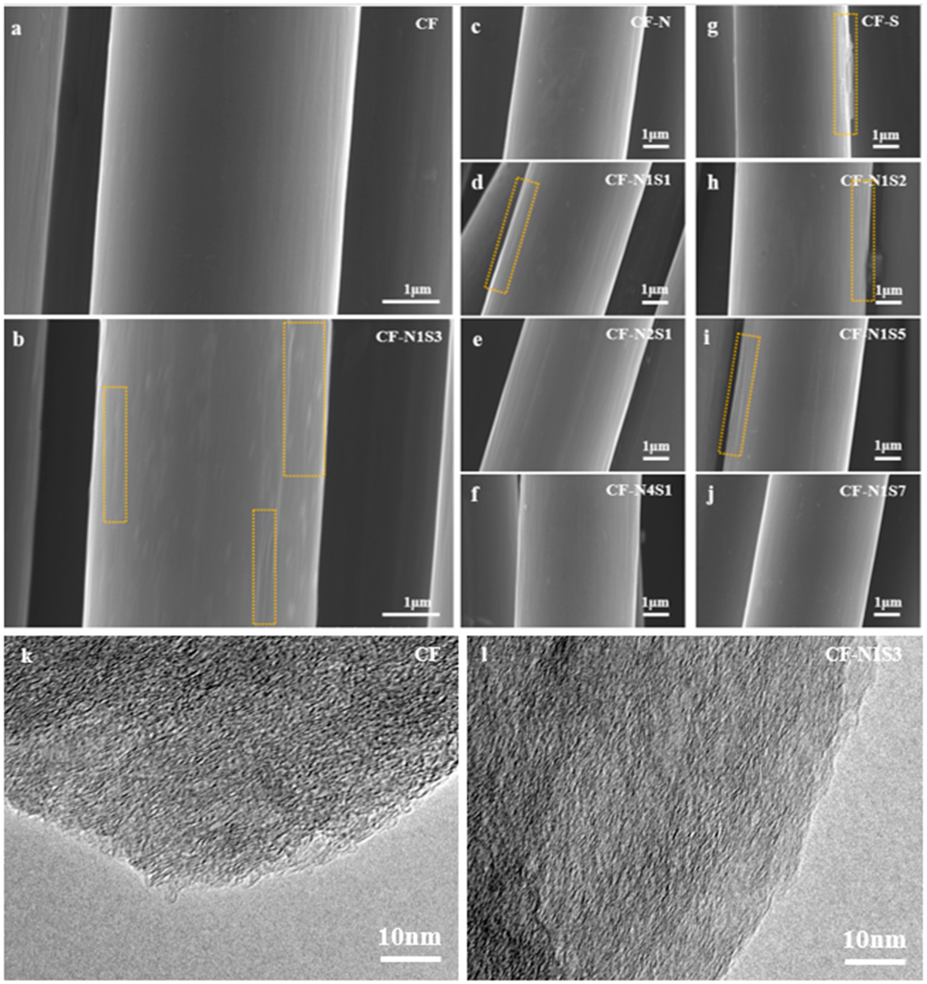
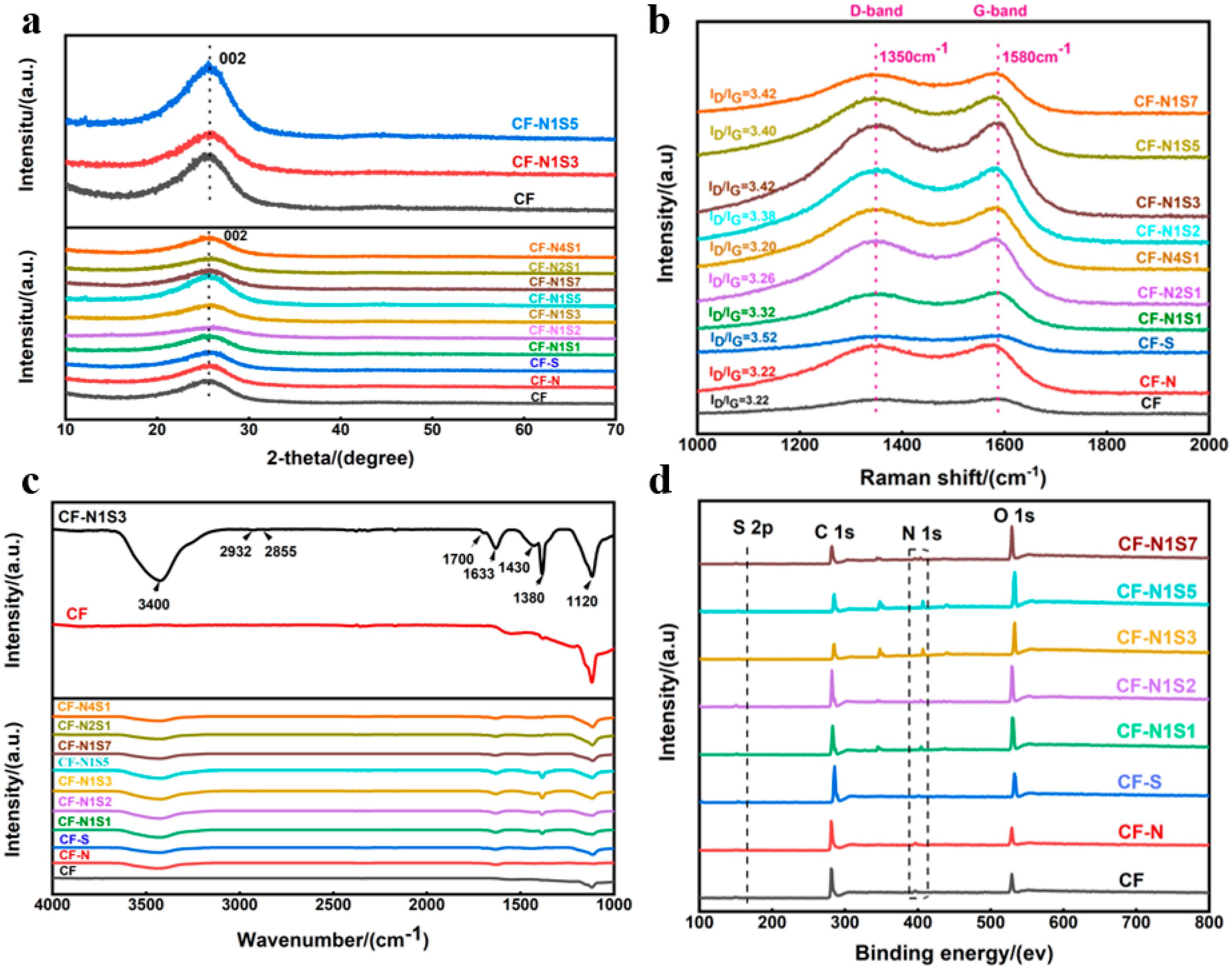
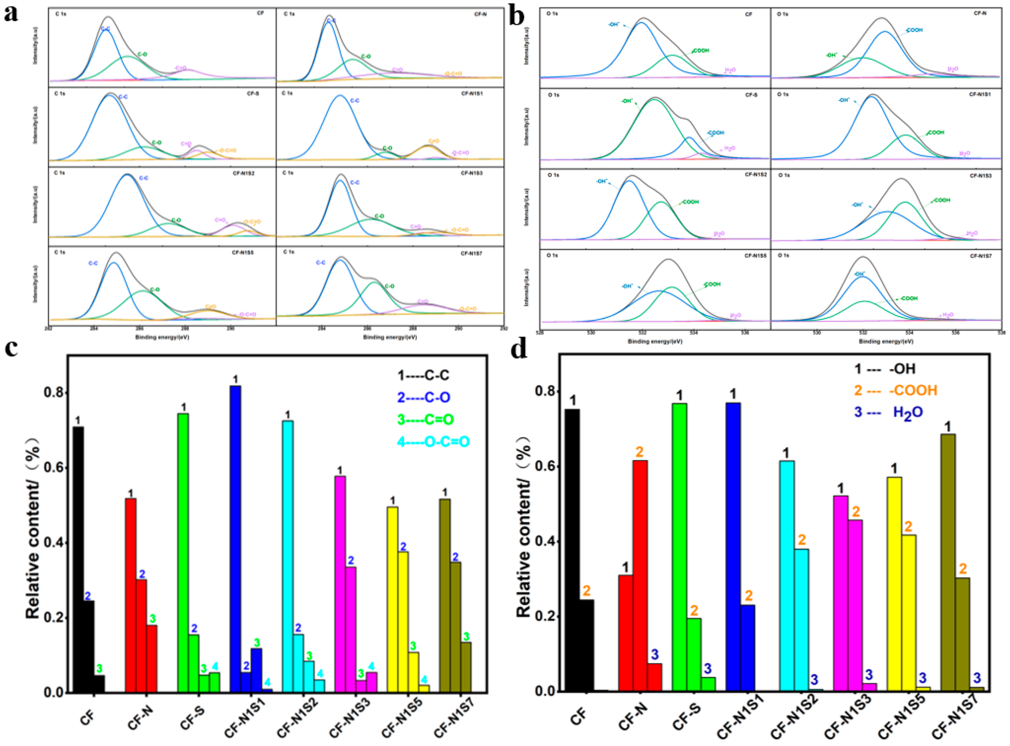
3.1. Analysis and Characterization of Mixed-Acid-Treated Carbon Fibers

Figure 2 shows the SEM of carbon fibers treated with different mixed acids. The surface of untreated carbon fibers is relatively smooth and flat, while the surface roughness of carbon fibers treated with mixed acids increases to varying degrees. For CF-N1S1, CF-N1S2, CF-N1S3, CF-N1S5, CF-N1S7, and CF-S, the number and depth of grooves on the surface of carbon fibers gradually increased with the increase in the proportion of concentrated sulfuric acid. This shows that concentrated sulfuric acid can etch the fiber surface under ultrasonic and hydrothermal conditions and increase the surface roughness of the fiber, which helps to improve the surface activity of the fiber. From the TEM diagram of original CFs and CF-N1S3, the graphite microcrystalline structure of carbon fibers can be observed. The disordered graphite structure of the fibers does not change before and after acid-mixing treatment, which indicates that acid-mixing ultrasonic hydrothermal treatment will not affect the amorphous carbon structure of carbon fibers. Figure 3a shows the XRD patterns of CFs treated with different mixed acids. There is an obvious diffraction peak at about 25.3° in all CFs treated with mixed acids, which corresponds to the (002) crystal plane diffraction peak of graphite microcrystals on the CF surface [35]. Figure 3b shows the Raman spectra of CFs treated with different mixed acids. The Raman curves of all samples show two distinct characteristic peaks, one of which is the disordered vibrational D peak around 1350 cm−1 representing the structural defects or edges in the graphene sheets, and the other is the G peak near 1580 cm−1, which is caused by the in-plane vibration of sp2 carbon atoms [36]. For carbon materials, the area ratio R (ID/IG) of D peak to G peak is usually used to describe the graphitization degree of carbon materials. The smaller the R value, the higher the graphitization degree of CFs. It can be seen that compared with the original CFs, for CF-S, CF-N1S1, CF-N1S2, CF-N1S3, CF-N1S5, and CF-N1S7, the R value is positively correlated with the amount of concentrated sulfuric acid. The graphite microcrystals on the surface of the CFs are slightly oxidized under the actions of ultrasound and mixed acid, leading to the formation of a series of oxygen-containing functional groups. The induced defects on the surface reduce the graphitization degree of the CFs’ surface, resulting in the increased R value.
The infrared spectra are shown in Figure 3c. The surface of carbon fibers treated with mixed acids includes rich oxygen-containing functional groups such as carboxyl and hydroxyl groups, while the surface of the original carbon fibers contains almost no functional groups. For CF-N1S3, due to its carbon structure, the absorption peak at about 1633 cm−1 represents the stretching vibration of the C=C skeleton. The 3400 cm−1 and 1430 cm−1 absorption peaks represent the stretching vibration and deformation vibration of –OH, respectively. This indicates the carboxyl group on the fiber surface. For hydrocarbon functional groups, the absorption peaks at 2932 cm−1, 2855 cm−1, 1430 cm−1, and 1380 cm−1 correspond to C–H bonds. The absorption peaks at about 3400 cm−1 and 1633 cm−1 are the characteristic peaks of N–H. 1700 cm−1 and 1120 cm−1 represent the C=O and C–O groups, respectively. Figure 3d shows the XPS full spectrum of carbon fibers treated with different mixed acids. The O1s intensity in the original carbon fiber spectrum is low, and there is almost no N1s peak. After different mixed acid treatments, the O1s peak intensity is significantly improved.
In order to explore the change of chemical bond on the surface of carbon fibers after mixed acid treatment, the C1s spectrum with bond energy of 282–292 eV and O1s spectrum with bond energy of 528–538 eV were fitted using XPS-PEEK software(version number:6.0.72.9589). The peak fitting curve and the relative content of chemical bond are shown in Figure 4. The C1s spectrum is divided into four peaks, in which 284.8 eV, 286.2 eV, 288.5 eV, and 289 eV represent C–C, C–O, C=O, and –O–C=O, respectively [37]. According to Figure 4a,c, the oxygen-containing functional groups on the surface of the original carbon fibers are mainly contributed via C–O such as hydroxyl and ether bonds. After the acid-mixing ultrasonic hydrothermal treatment, the active carbon atoms on the surface of carbon fibers are oxidized to form C–O, C=O, O–C=O and other oxygen-containing functional groups. For CF-N1S3 and CF-N1S5, the relative content of C–C is low, and the proportion of C–O, C=O, and –O–C=O is relatively large. Figure 4b,d show the O1s peak fitting curve and its chemical bond relative content; all O1s spectra are divided into three peaks, in which 532 eV, 533.5 eV, and 535 eV represent –OH, –COOH, and H2O, respectively [27]. The oxygen on the surface of the original carbon fibers mainly exists in the form of single bond, with only a small amount of –COOH. After mixed acid treatment, the relative content of –COOH increases, and the relative content of –OH decreases, which indicates that the surface oxidation degree of the carbon fibers increases. The mixed acid treatment reduces the relative content of C–C on the surface of carbon fibers, while the relative contents of C–O and C=O on the surface of the fibers increase, which indicates that a certain number of graphene quantum dots (GQDs) are formed on the surface of carbon fibers during the mixed acid treatment, caused by the oxidation of large-size graphite [38,39,40,41].
Figure 5 shows the mechanism diagram for strengthening oxygen-containing functional groups and GQDs on the surface of carbon fibers treated with mixed acid, which can better explain the formation process of GQDs. During the ultrasonic process, the activated carbon atoms on the surface of carbon fibers are oxidized under the action of mixed acid, and the oxygen-containing functional groups are introduced into the oxidized, amorphous carbon layer. These functional groups tend to be arranged in a straight line on the carbon skeleton. Then, the oxidized graphite layer is treated under hydrothermal conditions, and its oxygen-containing groups are removed, which leads to the rupture of the layer and the formation of GQDs. Abundant oxygen-containing functional groups and a certain number of GQDs can increase the surface activity of carbon fibers and provide more active reaction sites in the electrochemical process, which improves some pseudocapacitance properties and the electrochemical properties of carbon fibers.

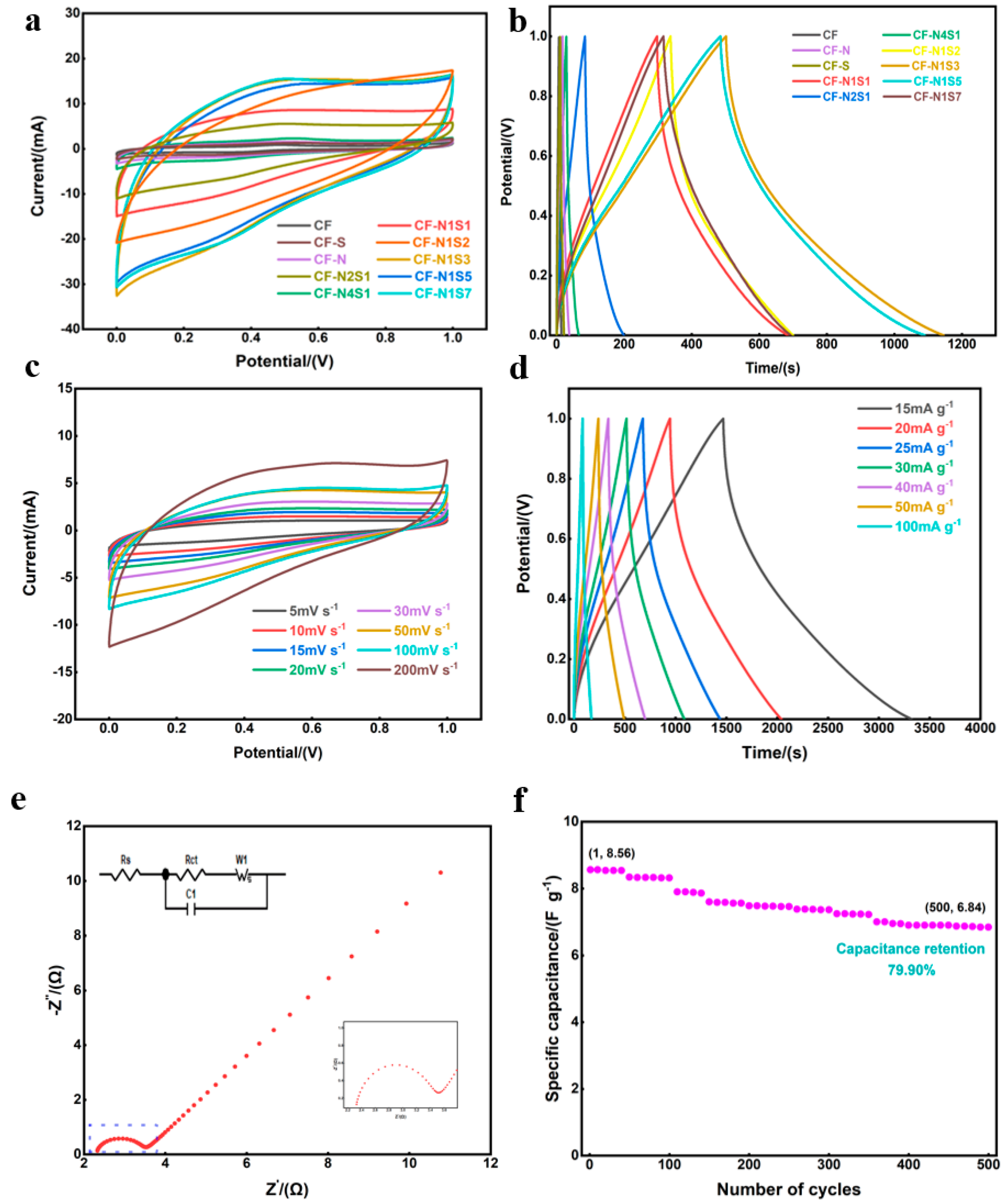
3.2. Electrochemical Properties of Carbon Fiber Electrodes

Figure 6a shows the CV curves of carbon fiber electrodes at 20 mV s−1. The CV curve of the original carbon fibers is almost a straight line, which means its specific capacitance is almost zero. Compared with the original carbon fibers, the specific capacitances of CF-N and CF-S are slightly improved, but their values are still very low and do not have practical application value. The specific capacitances of the carbon fiber electrodes treated with mixed acid increase in varying degrees. For CF-N1S1, CF-N1S2, CF-N1S3, CF-N1S5, and CF-N1S7, the CV curve loses its “nearly rectangular” shape, and the redox peak can clearly be seen in the CV curve, indicating that the capacitance behavior is the joint action of electric double-layer capacitance and faraday capacitance. According to the CV curve integral area, the specific capacitances first increase and then decrease, and the curve area of CF-N1S3 is the largest, indicating the best capacitance property. Figure 6b shows the GCD curve of carbon fiber electrodes at 25 mA g−1. It can be calculated that the specific capacitance of the original CFs’ electrodes is only 0.1825 F g−1. For the CF electrodes treated with mixed acid, the specific capacitances clearly increase. Additionally, the specific capacitances of CF-N1S1, CF-N1S2, CF-N1S3, CF-N1S5, and CF-N1S7 reach 9.7 F g−1, 11.2 F g−1, 16.1 F g−1, 15.1 F g−1, and 9.425 F g−1, respectively. Among all fiber electrodes, the specific capacitance of the CF-N1S3 electrode reaches the maximum. Combined with surface morphology, phase structure, surface functional group distribution, and elemental analysis of CFs, the excellent electrochemical performance of CF-N1S3 results from its rough surface structure, rich oxygen-containing functional groups, and a certain number of GQDs. Rough carbon fiber surface and GQDs can improve the double-layer capacitance of fiber electrodes by increasing the fiber’s specific surface area and its surface activity. The oxygen-containing functional groups can not only improve the surface activity of a fiber, but they also have a redox reaction with electrolyte ions during charge and discharge, so as to increase the pseudocapacitance of fiber electrodes.
Figure 6c shows the cyclic voltammetry curve of carbon fiber electrodes at different scanning speeds. In order to ensure the stability of electrolyte system, the voltage window of the CF-N1S3 electrode was set to 0–1.0 V. At a low sweep speed, there is an obvious redox peak on the curve, which indicates the redox reaction in the process of energy storage, caused by the oxygen-containing functional groups within the fiber electrodes. With an increase in scanning speed, the intensity of the redox peak decreases gradually until it disappears, due to the insufficient redox reaction at a higher scanning speed.
Figure 6d shows the GCD curve of the CF-N1S3 electrode under different current densities. The curve shows an asymmetric triangle, which is a typical feature of pseudocapacitor material. At the moment of charge–discharge conversion, the curve shows a vertical voltage drop, which is due to the internal resistance and solution contact resistance of the fiber electrodes. When the current density is 15 mA g−1, 30 mA g−1, and 50 mA g−1, the specific capacitances of CF-N1S3 are 27.83 F g−1, 17.04 F g−1, and 12.67 F g−1, respectively (Table 2). Hence, the CF-N1S3 electrode has an excellent electrochemical and magnification performance. In order to analyze the internal resistance of fiber electrodes and to understand the ion diffusion process, an impedance test of CF-N1S3 was carried out, and its Nyquist diagram is shown in Figure 6e. The Nyquist diagram consists of a high-frequency semicircle and a straight line in the low-frequency region, in which the semicircle corresponds to the charge transfer resistance (RCT) at the interface between the electrode and the electrolyte, the intercept between the semicircle and the real axis represents the internal resistance (RS) of the electrode, and the straight line in the low-frequency region is related to the capacitive performance of the material [42]. Through spectrum analysis and data fitting, the RS and RCT of the CF-N1S3 electrode are 2.3 Ω and 1.2 Ω, respectively. The RS and RCT of the CF-N1S3 electrode are very small, indicating that the internal resistance and charge transfer resistance of the fiber electrodes are low. This is very beneficial to charge transfer and reaction kinetics. Figure 6f shows the cycle stability curve of the CF-N1S3 electrode for 500 cycles at 100 mA g−1. After a 500-cycle test, its specific capacitance changes from the initial 8.56 F g−1 to 6.84 F g−1, and the capacitance retention is 79.90%, indicating that the CF-N1S3 electrode has an excellent cycle stability. Figure 7a shows the relationship between the energy density and power density of the CF-N1S3 electrode. When the power density of the CF-N1S3 electrode is 7.5 W kg−1, its energy density can reach 3.86 Wh kg−1, while its energy density can be maintained at 1.20 Wh kg−1 with a power density of 50 W kg−1. Our reported values are in line with other studies featuring flexible supercapacitor electrodes with or without active materials, as shown in Figure 7b. Compared to other surface-active methods, the mixed acid treatment method is simpler and more efficient, and we directly use carbon fibers as fiber electrodes, which avoids problems such as the active material falling off the substrate [43,44,45,46,47].
A series of electrochemical tests and characterization show that the CF-N1S3 electrode has an excellent electrochemical performance. In order to explore the capacitor performance and practical application effect of the CF-N1S3 electrode, CF-N1S3 electrode was assembled into an all-solid-state flexible-fiber supercapacitor for testing and characterization.

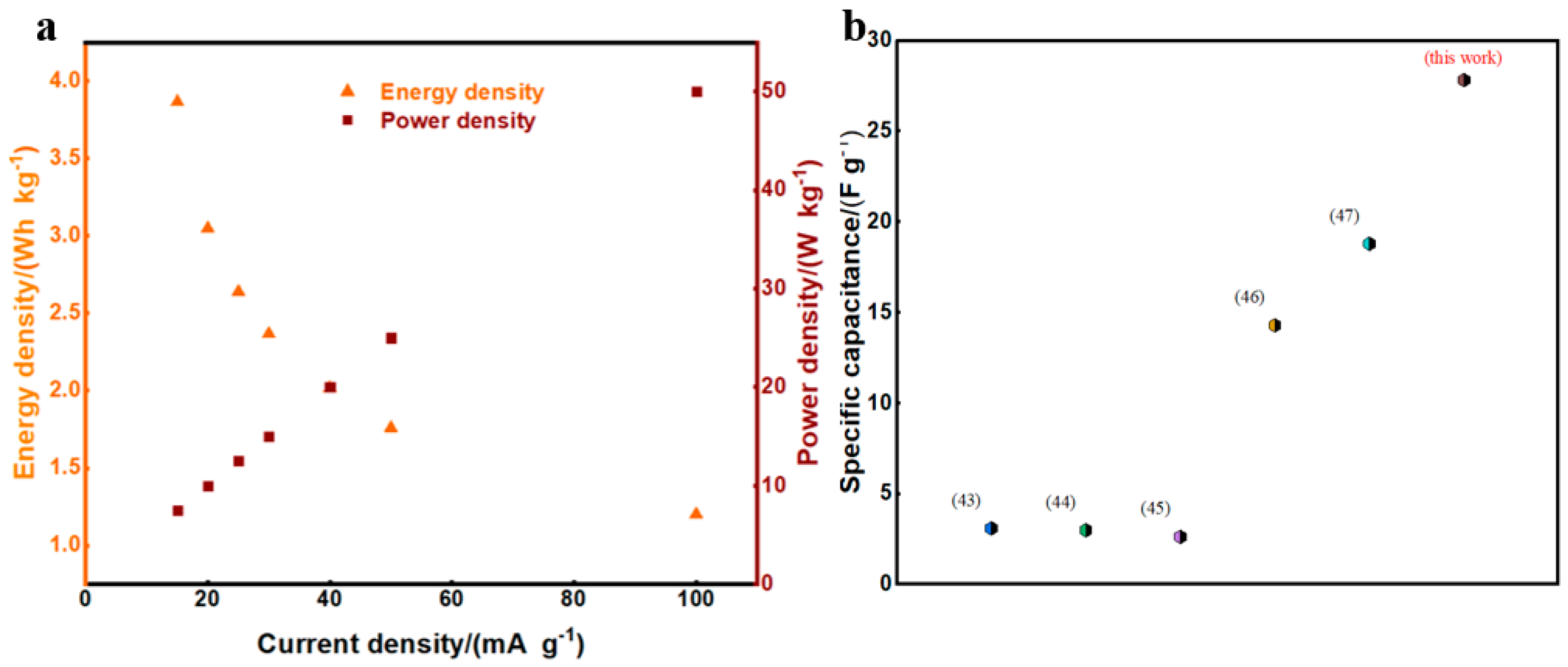
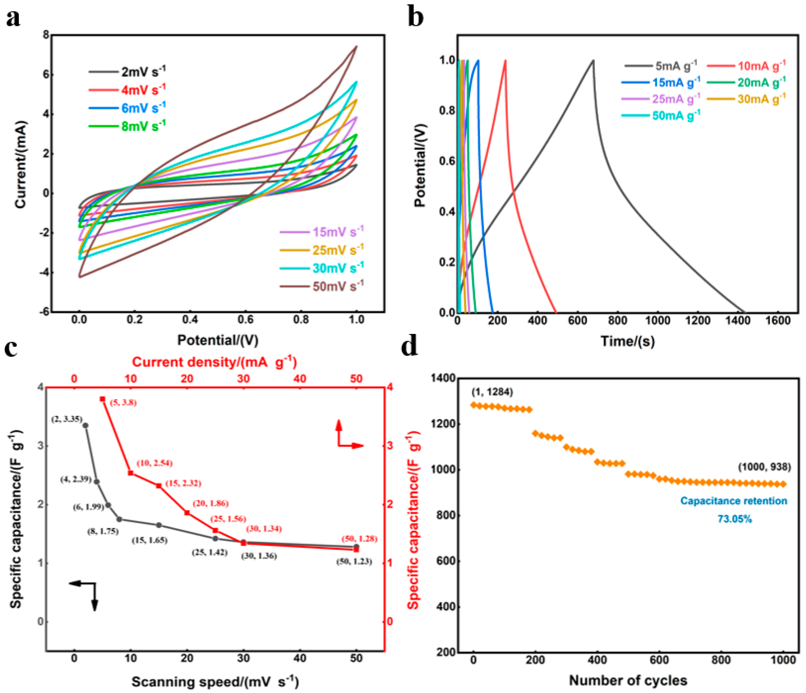
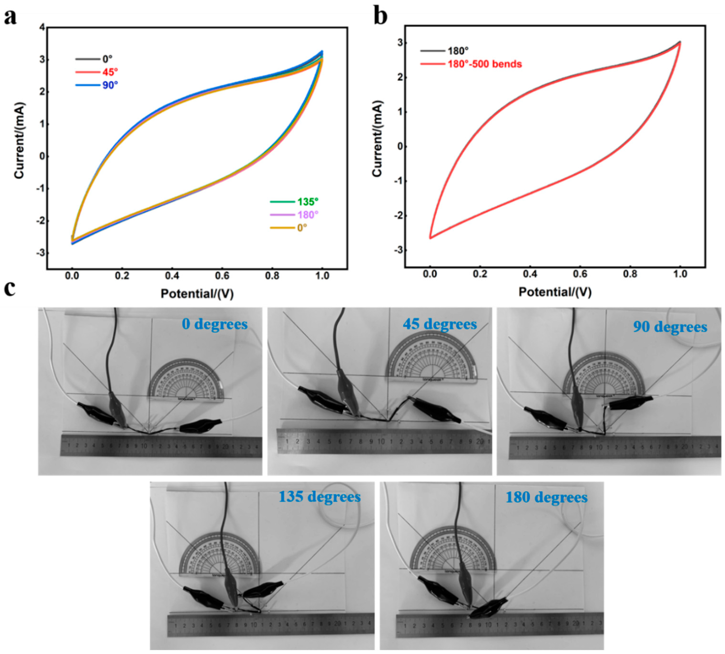
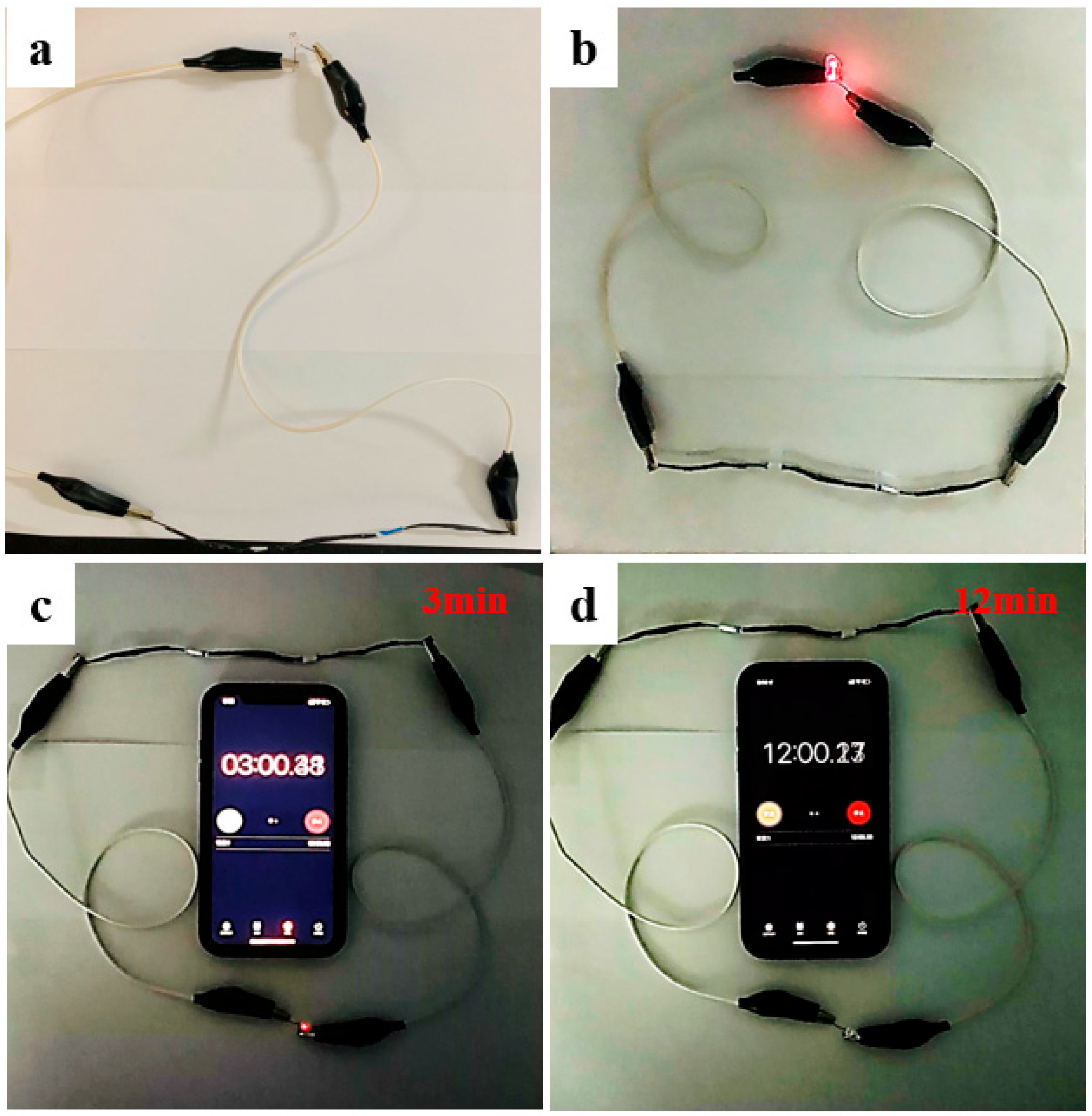
3.3. Electrochemical Performance of Flexible Supercapacitor

Figure 8a shows the CV curve of the capacitor. The curve shape at all scanning rates is nonrectangular, indicating both a redox reaction and charge adsorption and desorption in the process of energy storage. The specific capacitances of the capacitor are shown in Figure 8c (black curve). When the scanning speeds are 2 mV s−1, 6 mV s−1, and 15 mV s−1, the specific capacitances of the capacitor are 2.35 F g−1, 1.99 F g−1, and 1.65 F g−1, respectively. Figure 8b shows the GCD curve of the capacitor. The GCD curve features an asymmetric triangle, indicating that the redox reaction occurs on the electrode surface during charge and discharge. The mass-specific capacitances of the capacitor under different current densities can be seen in Figure 8c (red curve). When the current densities are 5 mA g−1, 15 mA g−1, and 30 mA g−1, the specific capacitances are 3.8 F g−1, 2.32 F g−1, and 1.56 F g−1, respectively. The cycle stability of the capacitors is tested, as shown in Figure 8d. The specific capacitance changes from 1284 mF g−1 to 938 mF g−1 after 1000 cycles at 15 mA g−1, and the capacitance retention rate reaches 73.05%, showing a good cycle stability.
Figure 9a shows the CV curve of capacitor bending at different angles at 30 mV s−1, and Figure 9c shows the optical picture corresponding to the test. There are almost no changes in the CV curves of the capacitor under bending angles of 45°, 90°, 135°, and 180°, indicating excellent bending properties of the capacitor. Figure 9b gives the CV curve of the capacitor bent 500 times at 180° at 30 mV s−1. The capacitor exhibits excellent flexural stability with a capacitance retention of almost 100% after 500 bending cycles at 180°, playing a very important role in practical application.
The capacitor was charged by the constant voltage in the experiment. The charging device was composed of three 1.5 V dry batteries in a series. After charging, when the capacitor was connected to the LED, the LED continuously emitted light. The optical photos before and after LED emission are shown in Figure 10a,b. A timer was used to record the LED luminous time, and the optical photos are shown in Figure 10c,d. When the LED lit up for 3 min, its brightness decreased slightly. After 6 min, its brightness decreased significantly, indicating that the electric energy stored in the capacitor is gradually dissipated in the form of thermal energy and light energy. The LED was completely extinguished after 12 min, indicating that the voltage of the capacitor was not enough to run the LED. At that point, the voltage of the capacitor measured using the multimeter was 1.5 V, which is less than the LED luminous voltage. The phenomenon of lighting the LED continuously shows that the prepared CF-N1S3 electrode and the assembled capacitor have practical application value.

4. Conclusions

In this paper, we demonstrate how the electrochemical performance of carbon fibers improved significantly after mixed acid treatment. The results show that carbon fiber electrodes have the best electrochemical performance when the volume ratio of concentrated H2SO4 to concentrated HNO3 is 3:1. Specifically, the capacitance of the CF-N1S3 electrode is as high as 27.83 F g−1 at 15 mA g−1, while that of the original carbon fibers is only 0.1825 F g−1. The electrode also shows an excellent cycle stability, considering that the capacitance retention is 79.9% after 500 cycles at 100 mA g−1. Its energy density can reach 3.86 Wh kg−1 with a power density of 7.5 W kg−1. The excellent electrochemical performance of CF-N1S3 results from its rough surface structure, rich oxygen-containing functional groups, and a certain number of GQDs. The rough carbon fibers’ surfaces and GQDs can improve the double-layer capacitance of fiber electrodes, by increasing the fibers’ specific surface areas surface activities. The oxygen-containing functional groups can not only improve the surface activity of fiber, but they also have a redox reaction with electrolyte ions during charge and discharge, so as to increase the pseudocapacitance of fiber electrodes. Without adding any active materials, the CF-N1S3 electrode was assembled into an all-solid-state flexible-fiber supercapacitor. The capacitor shows excellent electrochemical performance with a capacitance retention of 73.05% after 1000 cycles at 15 mA g−1. The capacitor also features excellent bending performance with capacitance retention of almost 100% after bending 180° 500 times. In practical application, the capacitor can continuously light an LED bulb for 12 min.

Author Contributions

Conceptualization, Y.W. (Yongbo Wang), H.L. and Y.W. (Yanxiang Wang); data curation, Y.W. (Yongbo Wang); funding acquisition, H.L. and Y.W. (Yanxiang Wang); investigation, Y.W. (Yongbo Wang); methodology, Y.W. (Yongbo Wang); project administration, H.L. and Y.W. (Yanxiang Wang); software, Y.W. (Yongbo Wang) and X.X.; supervision, Y.W. (Yanxiang Wang); validation, Y.W. (Yongbo Wang); visualization, Y.W. (Yongbo Wang); writing—original draft, Y.W. (Yongbo Wang); writing—review and editing, Y.W. (Yongbo Wang), X.X. and B.C. All authors have read and agreed to the published version of the manuscript.

Funding

This work was supported by the Natural Science Foundation in Shandong Province (ZR2021ME194, ZR2020ME039, ZR2020ME134) and the National Natural Science Foundation of China (Grant No. 52171038). This work was also supported by special funding from the project of the Taishan Scholar in Construction Engineering and the project for the University Innovation Team in Jinan City (2020GXRC019).

Data Availability Statement

The authors confirm that the data supporting the findings of this study are available within the article.

Acknowledgments

The authors thank the editors and the anonymous reviewers for their valuable comments on this manuscript. The authors also acknowledge the support of technical staff for assisting with preparation and analysis of samples.

Conflicts of Interest

The authors declare no conflict of interest.

References

  1. Hou, R.; Gund, G.S.; Qi, K.; Nakhanivej, P.; Liu, H.; Li, F.; Xia, B.Y.; Park, H.S. Hybridization design of materials and devices for flexible electrochemical energy storage. Energy Storage Mater. 2019, 19, 212–241. [Google Scholar] [CrossRef]
  2. Zhao, Z.Y.; Xia, K.Q.; Hou, Y.; Zhang, Q.H.; Ye, Z.Z.; Lu, J.G. Designing flexible, smart and self-sustainable supercapacitors for porta-ble/wearable electronics: From conductive polymers. Chem. Soc. Rev. 2021, 50, 12702–12743. [Google Scholar] [CrossRef]
  3. Li, X.; Chen, X.; Jin, Z.; Li, P.; Xiao, D. Recent progress in conductive polymers for advanced fiber-shaped electrochemical energy storage devices. Mater. Chem. Front. 2021, 5, 1140–1163. [Google Scholar] [CrossRef]
  4. Chen, K.; Wang, Q.; Niu, Z.; Chen, J. Graphene-based materials for flexible energy storage devices. J. Energy Chem. 2018, 27, 12–24. [Google Scholar] [CrossRef] [Green Version]
  5. Dong, P.; Rodrigues, M.-T.F.; Zhang, J.; Borges, R.S.; Kalaga, K.; Reddy, A.L.; Silva, G.G.; Ajayan, P.M.; Lou, J. A flexible solar cell/supercapacitor integrated energy device. Nano Energy 2017, 42, 181–186. [Google Scholar] [CrossRef]
  6. Song, W.-J.; Lee, S.; Song, G.; Bin Son, H.; Han, D.-Y.; Jeong, I.; Bang, Y.; Park, S. Recent progress in aqueous based flexible energy storage devices. Energy Storage Mater. 2020, 30, 260–286. [Google Scholar] [CrossRef]
  7. Lee, J.-H.; Yang, G.; Kim, C.-H.; Mahajan, R.L.; Lee, S.-Y.; Park, S.-J. Flexible solid-state hybrid supercapacitors for the internet of everything (IoE). Energy Environ. Sci. 2022, 15, 2233–2258. [Google Scholar] [CrossRef]
  8. Fu, W.; Turcheniuk, K.; Naumov, O.; Mysyk, R.; Wang, F.; Liu, M.; Kim, D.; Ren, X.; Magasinski, A.; Yu, M.; et al. Materials and technologies for multifunctional, flexible or integrated supercapacitors and batteries. Mater. Today 2021, 48, 176–197. [Google Scholar] [CrossRef]
  9. Liang, J.; Jiang, C.; Wu, W. Toward fiber-, paper-, and foam-based flexible solid-state supercapacitors: Electrode materials and device designs. Nanoscale 2019, 11, 7041–7061. [Google Scholar] [CrossRef]
  10. Pan, Z.; Jiang, Y.; Yang, P.; Wu, Z.; Tian, W.; Liu, L.; Song, Y.; Gu, Q.; Sun, D.; Hu, L. In Situ Growth of Layered Bimetallic ZnCo Hydroxide Nanosheets for High-Performance All-Solid-State Pseudocapacitor. ACS Nano 2018, 12, 2968–2979. [Google Scholar] [CrossRef]
  11. Sahoo, S.; Kumar, R.; Joanni, E.; Singh, R.K.; Shim, J.-J. Advances in pseudocapacitive and battery-like electrode materials for high performance supercapacitors. J. Mater. Chem. A 2022, 10, 13190–13240. [Google Scholar] [CrossRef]
  12. Shen, Y.K.; Lv, Y.Y.; Chi, H.Z.; Xi, J.; Xiong, Q.; Qin, H. All-Solid-State Supercapacitor with High Volumetric Energy for Flexible Application. J. Electrochem. Soc. 2019, 166, A2797–A2804. [Google Scholar] [CrossRef]
  13. Hua, X.; Shen, G.J.; Du, Y. Carbon Materials Electrodes: Electrochemical Analysis Applications. Appl. Mech. Mater. 2012, 248, 262–267. [Google Scholar] [CrossRef]
  14. Simon, P.; Gogotsi, Y. Materials for electrochemical capacitors. Nat. Mater. 2008, 7, 845–854. [Google Scholar] [CrossRef] [PubMed] [Green Version]
  15. Diez, N.; Díaz, P.; Álvarez, P.; González, Z.; Granda, M.; Blanco, C.; Santamaría, R.; Menéndez, R. Activated carbon fibers prepared directly from stabilized fibers for use as electrodes in supercapacitors. Mater. Lett. 2014, 136, 214–217. [Google Scholar] [CrossRef]
  16. Zhu, K.; Wang, Y.; Tang, J.A.; Guo, S.; Gao, Z.; Wei, Y.; Chen, G.; Gao, Y. A high-performance supercapacitor based on activated carbon fibers with an optimized pore structure and oxygen-containing functional groups. Mater. Chem. Front. 2017, 1, 958–966. [Google Scholar] [CrossRef]
  17. Wang, G.; Liang, R.; Liu, L.; Zhong, B. Improving the specific capacitance of carbon nanotubes-based supercapacitors by combining introducing functional groups on carbon nanotubes with using redox-active electrolyte. Electrochim. Acta 2014, 115, 183–188. [Google Scholar] [CrossRef]
  18. Wang, Q.; Wen, Z.; Li, J. Carbon Nanotubes/TiO2 Nanotubes Hybrid Supercapacitor. J. Nanosci. Nanotechnol. 2007, 7, 3328–3331. [Google Scholar] [CrossRef]
  19. Maqsood, M.F.; Raza, M.A.; Rehman, Z.U.; Tayyeb, A.; Makhdoom, M.A.; Ghafoor, F.; Latif, U.; Khan, M.F. Role of Solvent Used in De-velopment of Graphene Oxide Coating on AZ31B Magnesium Alloy: Corrosion Behavior and Biocompatibility Analysis. Nanomaterials 2022, 12, 3745. [Google Scholar] [CrossRef]
  20. Shinde, P.A.; Khan, M.F.; Rehman, M.A.; Jung, E.; Pham, Q.N.; Won, Y.; Jun, S.C. Nitrogen-doped carbon integrated nickel–cobalt metal phosphide marigold flowers as a high capacity electrode for hybrid supercapacitors. Crystengcomm 2020, 22, 6360–6370. [Google Scholar] [CrossRef]
  21. Liu, Y.D.; Kumar, S. Recent Progress in Fabrication, Structure, and Properties of Carbon fibers. Polym. Rev. 2012, 52, 234–258. [Google Scholar] [CrossRef]
  22. Shirvanimoghaddam, K.; Hamim, S.U.; Akbari, M.K.; Fakhrhoseini, S.M.; Khayyam, H.; Pakseresht, A.H.; Ghasali, E.; Zabet, M.; Munir, K.S.; Jia, S.; et al. Carbon fiber reinforced metal matrix composites: Fabrication processes and properties. Compos. Part A Appl. Sci. Manuf. 2017, 92, 70–96. [Google Scholar] [CrossRef]
  23. Noh, J.; Yoon, C.-M.; Kim, Y.K.; Jang, J. High performance asymmetric supercapacitor twisted from carbon fibers/MnO2 and carbon fibers/MoO3. Carbon 2017, 116, 470–478. [Google Scholar] [CrossRef]
  24. Li, Y.; Lu, C.; Zhang, S.; Su, F.-Y.; Shen, W.; Zhou, P.; Ma, C. Nitrogen- and oxygen-enriched 3D hierarchical porous carbon fibers: Synthesis and superior supercapacity. J. Mater. Chem. A 2015, 3, 14817–14825. [Google Scholar] [CrossRef]
  25. Wang, J.; Kaskel, S. KOH activation of carbon-based materials for energy storage. J. Mater. Chem. 2012, 22, 23710–23725. [Google Scholar] [CrossRef]
  26. Zhang, Y.; Cong, Y.; Zhang, J.; Li, X.; Li, Y.; Dong, Z.; Yuan, G.; Cui, Z. Effects of activation temperatures on the surface structures and supercapacitive performances of porous carbon fibers. Surf. Coat. Technol. 2018, 349, 384–391. [Google Scholar] [CrossRef]
  27. Miao, Z.; Huang, Y.; Xin, J.; Su, X.; Sang, Y.; Liu, H.; Wang, J.-J. High-Performance Symmetric Supercapacitor Constructed Using Carbon Cloth Boosted by Engineering Oxygen-Containing Functional Groups. ACS Appl. Mater. Interfaces 2019, 11, 18044–18050. [Google Scholar] [CrossRef]
  28. Farag, M.A.E.-A.M.; Alkandary, L.A.; Alshatti, M.I.; Shoukeer, M.A.H. Congestive heart failure as a rare cause of unilateral breast edema: A case report & review of the literature. Egypt. J. Radiol. Nucl. Med. 2018, 49, 873–877. [Google Scholar]
  29. Jiang, X.; Cao, Y.; Li, P.; Wei, J.; Wang, K.; Wu, D.; Zhu, H. Polyaniline/graphene/carbon fiber ternary composites as supercapacitor electrodes. Mater. Lett. 2015, 140, 43–47. [Google Scholar] [CrossRef]
  30. Liu, W.; Fan, H.; Shen, W.; Qu, S. Facile and Sustainable Synthesis of Co3O4@Hollow-Carbon-Fiber for a Binder-Free Superca-pacitor Electrode. ChemistrySelect 2016, 1, 6469–6475. [Google Scholar] [CrossRef]
  31. Yuan, L.; Lu, X.-H.; Xiao, X.; Zhai, T.; Dai, J.; Zhang, F.; Hu, B.; Wang, X.; Gong, L.; Chen, J.; et al. Flexible Solid-State Supercapacitors Based on Carbon Nanoparticles/MnO2 Nanorods Hybrid Structure. ACS Nano 2012, 6, 656–661. [Google Scholar] [CrossRef] [PubMed]
  32. Li, S.; Wen, J.; Mo, X.; Long, H.; Wang, H.; Wang, J.; Fang, G. Three-dimensional MnO2 nanowire/ZnO nanorod arrays hybrid nanostructure for high-performance and flexible supercapacitor electrode. J. Power Sources 2014, 256, 206–211. [Google Scholar] [CrossRef]
  33. Li, Z.; An, Y.; Hu, Z.; An, N.; Zhang, Y.; Guo, B.; Zhang, Z.; Yang, Y.; Wu, H. Preparation of a two-dimensional flexible MnO2/graphene thin film and its application in a supercapacitor. J. Mater. Chem. A 2016, 4, 10618–10626. [Google Scholar] [CrossRef]
  34. Wang, Z.; Du, J.; Zhang, M.; Yu, J.; Liu, H.; Chai, X.; Yang, B.; Zhu, C.; Xu, J. Continuous preparation of high performance flexible asymmetric supercapacitor with a very fast, low-cost, simple and scalable electrochemical co-deposition method. J. Power Sources 2019, 437, 226827. [Google Scholar] [CrossRef]
  35. Lee, H.J.; Won, J.S.; Lim, S.C.; Lee, T.S.; Yoon, J.Y.; Lee, S.G. Preparation and Characterization of PAN-based Carbon fibers with Car-bonization Temperature. Text. Sci. Eng. 2016, 53, 103–108. [Google Scholar] [CrossRef] [Green Version]
  36. Couzi, M.; Bruneel, J.-L.; Talaga, D.; Bokobza, L. A multi wavelength Raman scattering study of defective graphitic carbon materials: The first order Raman spectra revisited. Carbon 2016, 107, 388–394. [Google Scholar] [CrossRef]
  37. Zheng, L.; Wang, Y.; Qin, J.; Wang, X.; Lu, R.; Qu, C.; Wang, C. Scalable manufacturing of carbon nanotubes on continuous carbon fibers surface from chemical vapor deposition. Vacuum 2018, 152, 84–90. [Google Scholar] [CrossRef]
  38. Kalluri, A.; Debnath, D.; Dharmadhikari, B.; Patra, P. Graphene Quantum Dots: Synthesis and Applications. Methods Enzym. 2018, 609, 335–354. [Google Scholar] [CrossRef]
  39. Peng, J.; Gao, W.; Gupta, B.K.; Liu, Z.; Romero-Aburto, R.; Ge, L.; Song, L.; Alemany, L.B.; Zhan, X.; Gao, G.; et al. Graphene Quantum Dots Derived from Carbon Fibers. Nano Lett. 2012, 12, 844–849. [Google Scholar] [CrossRef]
  40. Xie, M.; Su, Y.; Lu, X.; Zhang, Y.; Yang, Z.; Zhang, Y. Blue and green photoluminescence graphene quantum dots synthesized from carbon fibers. Mater. Lett. 2013, 93, 161–164. [Google Scholar] [CrossRef]
  41. Zheng, X.T.; Ananthanarayanan, A.; Luo, K.Q.; Chen, P. Glowing graphene quantum dots and carbon dots: Properties, syntheses, and biological applications. Small 2015, 11, 1620–1636. [Google Scholar] [CrossRef] [PubMed]
  42. Yang, C.; Zhang, L.; Hu, N.; Yang, Z.; Su, Y.; Xu, S.; Li, M.; Yao, L.; Hong, M.; Zhang, Y. Rational design of sandwiched polyaniline nanotube/layered graphene/polyaniline nanotube papers for high-volumetric supercapacitors. Chem. Eng. J. 2017, 309, 89–97. [Google Scholar] [CrossRef]
  43. Li, S.; Zhao, Y.; Zhang, Z.; Tang, H.; Song, H.; Wang, Y. Electrochemical and Mechanical Effects of Acid and Thermal Treatments of Carbon Fiber. Adv. Eng. Mater. 2015, 17, 52–57. [Google Scholar] [CrossRef]
  44. Li, S.; Zhao, Y.; Zhang, Z.; Tang, H. Preparation and characterization of epoxy/carbon fiber composite capacitors. Polym. Compos. 2015, 36, 1447–1453. [Google Scholar] [CrossRef]
  45. Qian, H.; Diao, H.; Shirshova, N.; Greenhalgh, E.S.; Steinke, J.G.; Shaffer, M.S.; Bismarck, A. Activation of structural carbon fibres for potential applications in multifunctional structural supercapacitors. J. Colloid Interface Sci. 2013, 395, 241–248. [Google Scholar] [CrossRef]
  46. Qian, H.; Kucernak, A.R.; Greenhalgh, E.S.; Bismarck, A.; Shaffer, M.S.P. Multifunctional Structural Supercapacitor Composites Based on Carbon Aerogel Modified High Performance Carbon Fiber Fabric. ACS Appl. Mater. Interfaces 2013, 5, 6113–6122. [Google Scholar] [CrossRef] [Green Version]
  47. Deka, B.K.; Hazarika, A.; Kwon, O.; Kim, D.; Park, Y.-B.; Park, H.W. Multifunctional enhancement of woven carbon fiber/ZnO nanotube-based structural supercapacitor and polyester resin-domain solid-polymer electrolytes. Chem. Eng. J. 2017, 325, 672–680. [Google Scholar] [CrossRef]
Figure 1. Ultrasonic hydrothermal process schematic diagram of carbon fibers.
Jcs 07 00231 g001
Figure 2. (aj) SEM of carbon fibers treated with different mixed acids; (k,l) TEM diagram of original CFs and CF-N1S3.
Jcs 07 00231 g002
Figure 3. (a) XRD patterns of CFs; (b) Raman spectra of CFs; (c) Infrared spectra of CFs; (d) XPS full spectrum of CFs.
Jcs 07 00231 g003
Figure 4. (a) Fitting curve of C1s peak on carbon fiber surfaces; (b) Fitting curve of O1s peak on carbon fiber surfaces; (c,d): Change of C and O chemical bond content on carbon fiber surfaces.
Jcs 07 00231 g004
Figure 5. Mechanism diagram for strengthening oxygen-containing functional groups and GQDs on the surface of CFs treated with mixed acid.
Jcs 07 00231 g005
Figure 6. (a) CV curves of carbon fiber electrodes (scanning speed: 20 mV s−1); (b) GCD curves of carbon fiber electrodes (current density 25 mA g−1); (c) CV curves of CF-N1S3 electrodes at different scanning speeds; (d) GCD curves of CF-N1S3 electrodes under different current densities; (e) Impedance spectrum of CF-N1S3 electrode, the built-in diagram is the fitting circuit (upper left) and the enlarged diagram of semicircle part (lower right); (f) Cyclic performance test of CF-N1S3 electrodes (current density: 100 mA g−1, 500 cycles).
Jcs 07 00231 g006
Figure 7. (a): Energy density and power density of CF-N1S3 electrode; (b): Capacitance values of various flexible electrode materials in the literature compared to this work.
Jcs 07 00231 g007
Figure 8. (a) CV curves of capacitors at different scanning speeds; (b) GCD curve of capacitor under different current densities; (c) The specific capacitances of capacitor under different scanning speeds and current densities; (d) Cycle stability curve of capacitor (current density: 15 mA g−1, 1000 cycles).
Jcs 07 00231 g008
Figure 9. (a) CV curve of capacitor under different bending angles (scanning speed is 30 mV s−1); (b) CV curve of capacitor bent 500 times at 180° (scanning speed is 30 mV s−1); (c) Optical photos of capacitor tested under different bending conditions.
Jcs 07 00231 g009
Figure 10. (a) Optical photo of capacitor connected to LED; (b) Optical photo of capacitor lighting LED; (c) Optical photos of capacitors with durations of 3 min lighting LED; (d) Optical photos of capacitors with durations of 12 min lighting LED.
Jcs 07 00231 g010
Table 1. Concentrated HNO3 and concentrated H2SO4 with different volume ratios.
H2SO4/mL 06040244090100105120
HNO3/mL 120608096803020150
VN:VS0:01:01:12:14:11:21:31:51:70:1
AbbreviationCFCF-NCF-N1S1CF-N2S1CF-N4S1CF-N1S2CF-N1S3CF-N1S5CF-N1S7CF-S
Table 2. Specific capacitances of CF-N1S3 electrode calculated at different scanning speeds and current densities.
Scanning Speed/(mV s−1)Specific Capacitance/(F g−1)Current Density/(mA g−1)Specific Capacitance/(F g−1)
522.331527.83
1018.082021.94
1515.502519.00
2013.793017.04
3011.834014.52
509.765012.67
1005.291008.65
2004.00
Disclaimer/Publisher’s Note: The statements, opinions and data contained in all publications are solely those of the individual author(s) and contributor(s) and not of MDPI and/or the editor(s). MDPI and/or the editor(s) disclaim responsibility for any injury to people or property resulting from any ideas, methods, instructions or products referred to in the content.

