Article

Metrology of Sheet Metal Distortion and Effects of Spot-Welding Sequences on Sheet Metal Distortion

by
Enkhsaikhan Boldsaikhan
1,*,
Michael Milhon
1,
Shintaro Fukada
2,
Mitsuo Fujimoto
2 and
Kenichi Kamimuki
3
1
Industrial, Systems & Manufacturing Engineering Department, Wichita State University, Wichita, KS 67260, USA
2
Corporate Technology Division, Kawasaki Heavy Industries, Ltd., Akashi 673-8666, Japan
3
Aerospace Division, Kawasaki Heavy Industries, Ltd., Kakamigahara 504-8710, Japan
*
Author to whom correspondence should be addressed.
J. Manuf. Mater. Process. 2023, 7(3), 109; https://doi.org/10.3390/jmmp7030109
Submission received: 13 April 2023 / Revised: 25 May 2023 / Accepted: 31 May 2023 / Published: 4 June 2023
(This article belongs to the Special Issue Frontiers in Friction Stir Welding and Processing)

Abstract

:
Refill friction stir spot welding (RFSSW) is an emerging solid-state welding technology that demonstrates an outstanding ability to join aerospace aluminum alloys. The thermomechanical processing of RFSSW may cause variations in the workpiece in the form of distortion. This study aims to establish a metrology method for sheet metal distortion with the intent to investigate the effects of RFSSW sequences on sheet metal distortion. The approach employs a robotic metrology system and the least squares method to measure and estimate the flatness of sheet metal before RFSSW and after RFSSW. The RFSSW experimentation produces five 10-spot-weld panels with five different RFSSW sequences, whereas the RFSSW sequences are based on the common practice of making sheet metal assemblies. A panel consists of two lap-welded sheets where the top sheet, a 6013-T6 aluminum alloy, is refill friction stir spot welded onto the bottom sheet, a 2029-T8 aluminum alloy. The results suggest that RFSSW sequences do have effects on sheet metal distortion. The panel with the worst distortion has a root-mean-square error of 0.8 mm as an average deviation from the ideal flatness.

1. Introduction

Refill friction stir spot welding (RFSSW) is an emerging solid-state spot-welding technology that demonstrates an outstanding ability to join aerospace aluminum alloys. It is a variant of friction stir spot welding (FSSW) [1]. RFSSW does not require any filler or foreign material for joining, and hence, no additional weight is added to the assembly. RFSSW thermo-mechanically produces a molecular level bond between workpieces. Since it does not involve major phase transitions during the welding process, RFSSW tends to preserve the parent metal properties. A refill friction stir spot weld exhibits a near flush surface finish with no tool exit hole (keyhole) due to the refilling action of the retractable welding tool [2,3,4]. Numerous researchers, such as Oberembt et al. [5] and Shen et al. [6], studied the RFSSW process parameters, metal microstructures, mechanical properties, and failure mechanisms of RFSSW. Riemann et al. [7] also investigated the microstructures and mechanical properties of tool-exit-hole repair welds made with RFSSW. De Castro et al. [8] investigated the stir zone geometries of RFSSW and their effects on mechanical failures. Patnaik et al. [9] studied the structural performances of a skin-stiffened compression panel with refill friction stir spot welds. Muci-Kühler et al. [10] proposed a finite element model of RFSSW using the Couette flow model of viscous fluid and attempted to predict the mechanical properties of RFSSW via simulation. Lacki and Derlatka et al. [11] studied RFSSW and resistance spot welding for joining dissimilar metal structures and performed finite element analysis. Berger et al. [12] established a two-dimensional (2D) axisymmetric thermomechanical model of the RFSSW process for a 7075-T6 aluminum alloy sheet and validated the model with experimental data.
Kawasaki Heavy Industries, Ltd. developed a robotic RFSSW system that has an unparalleled ability to produce refill friction stir spot welds for aircraft assemblies [3,13,14,15]. With the use of the robotic RFSSW system, Okada et al. [6,16] successfully demonstrated the potential aerospace applications of RFSSW. Moreover, Fukada and Ohashi et al. [14] demonstrated the potential automotive applications of RFSSW. In addition, Boldsaikhan and Fukada et al. [15,16] studied process development methods for RFSSW with an emphasis on aerospace applications. Lakshmi Balasubramaniam et al. [17,18] demonstrated the effects of refill spot weld spacing and edge margin on the mechanical properties and the failure mechanisms of refill-friction-stir-spot-welded panels. Some of these research outcomes were previously documented in academic theses [19,20,21,22]. Madras Karunamurthy [21] had authored an academic thesis on the raw measurement data of sheet metal distortion caused by RFSSW.
RFSSW offers an outstanding ability to join aluminum alloys, which is a potential capability for aerospace applications. Kubit and Trzepiecinski [23] studied the numerical modelling of RFSSW for the Alclad 7075-T6 aluminum alloy, which is a baseline aerospace aluminum alloy. Furthermore, Kluz et al. [24,25] investigated parameter optimization methods for the RFSSW process with an emphasis on aerospace applications.
In general, sheet metal distortion and the residual stresses produced by a sheet metal assembly process are critical challenges to address since they cause unfavorable stresses and unwanted structural variations in aircraft assemblies. Researchers studied sheet metal distortion and the residual stresses produced by riveting [26,27] and resistance spot welding [28,29] using finite element methods. Riveting is a standard joining method in aircraft manufacturing with well-established industrial standards [30].
RFSSW involves intense plastic deformation in the stir zone by the stirring action of the welding tool during the welding process [3,13,14,15,16,17,18]. Such thermomechanical processing may cause variations in the workpiece in the form of distortion. No major findings have yet been documented on measuring and characterizing the workpiece distortion that stems from RFSSW. To bridge this gap, this study aims to establish a metrology method for sheet metal distortion with the intent to investigate the effects of RFSSW sequences on sheet metal distortion. This study proposes a new way of measuring the shape of sheet metal with a three-dimensional (3D) robotic vision system as well as a new least-squares-based method that statistically estimates the sheet metal distortion via assessing the shape measurement data. Furthermore, this new metrology method is used to study the effects of RFSSW sequences on sheet metal distortion since no major findings have yet been documented on this particular topic. The instrumentation of this experiential study comprises a UR-10e collaborative robot with a 3D vision system for metrology and a Kawasaki RFSSW robot with an RFSSW end effector that are shown in Figure 1.

2. Materials and Methods

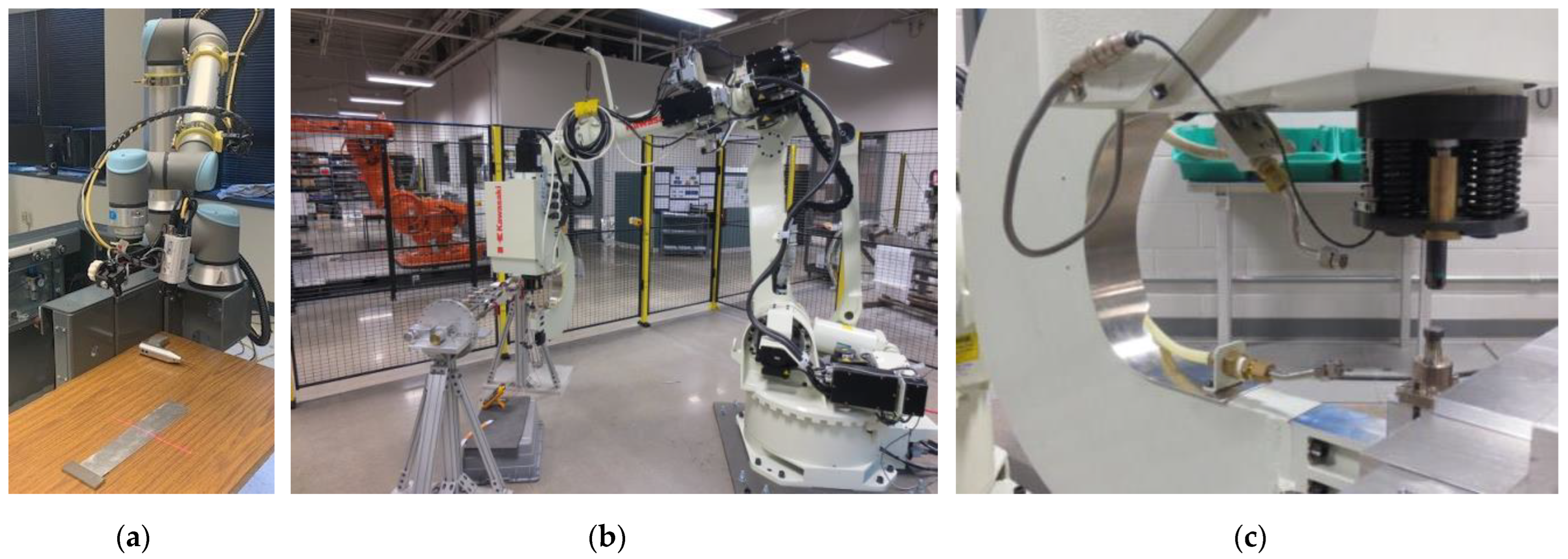
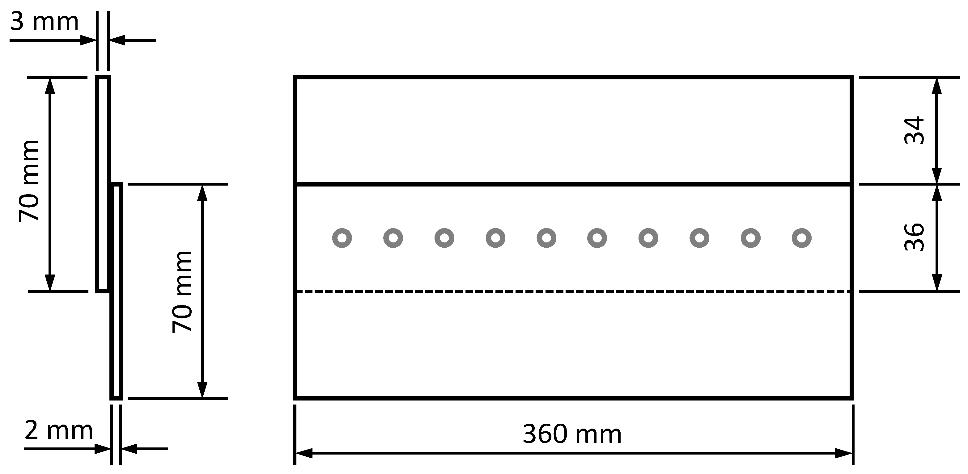
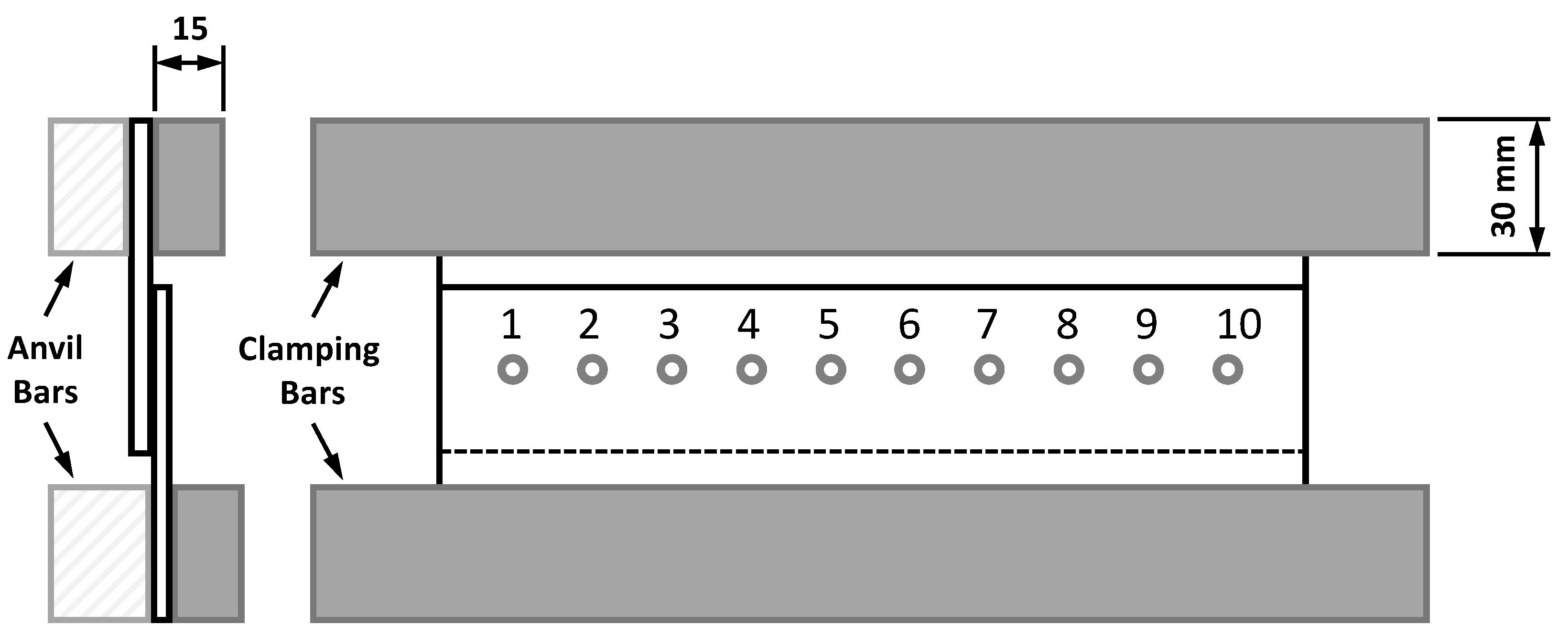
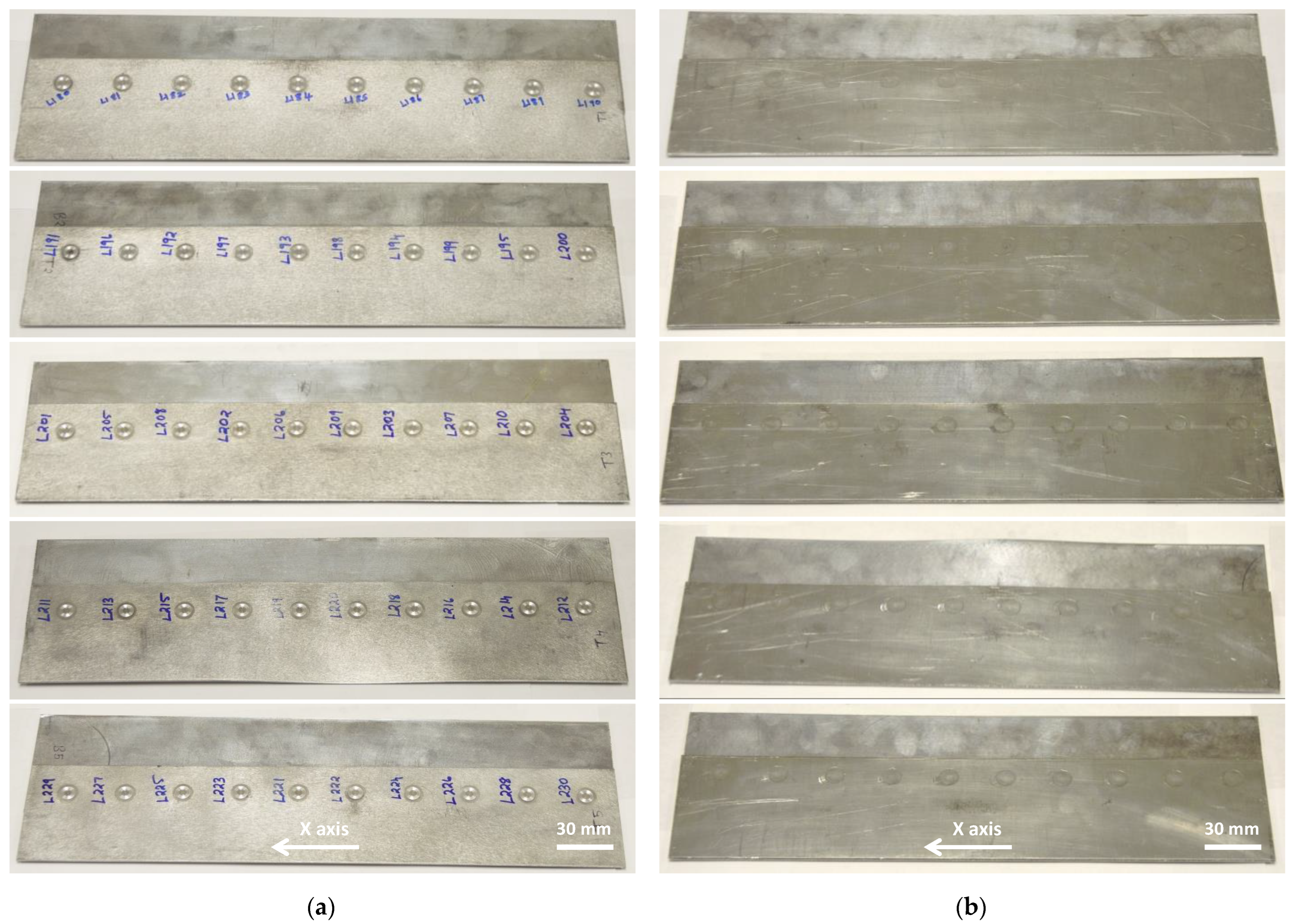
2.1. Panel Fabrication with Refill Friction Stir Spot Welding

The sheet metals used in this study are a 6013-T6 aluminum alloy (AA6013-T6) with a nominal thickness of 2 mm (0.08 inch) and a 2029-T8 aluminum alloy (AA2029-T8) with a nominal thickness of 3 mm (0.12 inch). The mechanical properties of the sheet metals are presented in Table 1. The top sheet metal is the 6013-T6 aluminum alloy, and the bottom sheet metal is the 2029-T8 aluminum alloy. The top sheet metal is refill friction stir spot welded onto the bottom sheet metal using the robotic RFSSW system in Figure 1. The configuration of the sheet metal panel is depicted in Figure 2. The panel clamping setup is depicted in Figure 3.
The panel clamping setup for welding is shown in Figure 3. Two rigid metal clamping bars, two rigid metal anvil bars, and four C-clamps are used for securely gripping the panel pieces during the entire time for producing 10 spot welds. The C-clamps are applied to the furthest ends of the gripping bars with a gripping force of approximately 800 N (180 lbf).
According to Figure 2 and Figure 3, a panel must have evenly spaced 10 refill spot welds. The refill spot weld diameter is 9 mm, which is the shoulder diameter of the welding tool. The spot weld spacing is 36 mm, and the edge margin is 18 mm. These arrangements are based on the study documented by Lakshmi Balasubramaniam et al. [17]. The spot weld spacing is the distance between the centers of two nearby spot welds. The edge margin is the distance between the center of the spot weld and the edge of the panel.
According to the setup in Figure 3, the spots for RFSSW are labeled from 1 to 10. This study employed five different sequences for RFSSW and produced one panel with each sequence. Each sequence specifies the order of the panel spots for RFSSW. Each panel was securely clamped as shown in Figure 3 throughout the entire time for making 10 refill spot welds according to a specified sequence. Each refill spot weld was made under the same welding condition. Panels and their RFSSW sequences are provided in Table 2.
A panel has 10 spots in a row for RFSSW. These 10 spots can be welded in 10! (=3,628,800) different RFSSW sequences, whereas 10! is the total number of permutations without repetitions. Practically, this number of RFSSW sequences is too big to experiment with. Therefore, the strategy for choosing the five RFSSW sequences in Table 2 is based on common practice of producing sheet metal assemblies. The initial three sequences in Table 2 iteratively produce spot welds from one end of the panel to another end of the panel by skipping no spot, one spot, and two spots at a time, respectively. The fourth sequence starts with producing two spot welds at the two ends of the panel and then symmetrically advances toward the center of the panel so that the spot welds close in on the center of the panel. The fifth sequence does the opposite of the fourth sequence. It starts with producing a weld at the center of the panel and then symmetrically advances toward the two ends of the panel so that the spot welds symmetrically spread away from the center of the panel to the two ends of the panel. These RFSSW sequences are defined in Table 2 with their associated panel labels.
The C-frame RFSSW end effector has a cylindrical welding tool inside a spring-loaded cylindrical clamp tip at one end and an opposing anvil at the other end as shown in Figure 1c. The welding tool for RFSSW consists of a retractable probe with a diameter of 6 mm inside a hollow shoulder with a diameter of 9 mm. The probe and the shoulder rotate at the same pre-specified spindle speed and move in opposite directions to perform plunging and refilling actions during the welding process. However, the spring-loaded cylindrical clamp tip and the opposing anvil do not rotate. They securely grip the workpieces during the welding process [3,13,14,15,16,17,18].
The welding tool starts with the probe and the shoulder in alignment. It rotates at the pre-specified spindle speed throughout the welding process. When the rotating tool touches the top surface of the workpiece, friction between the welding tool and the workpiece produces heat that is enough to make the workpiece locally plasticized. Once the workpiece becomes soft enough, the shoulder plunges to a pre-specified plunge depth in the workpiece, while the probe simultaneously retracts at a pre-specified probe speed to draw away the plasticized metal displaced by the plunging shoulder. The welding tool dwells at the pre-specified plunge depth for a bit. Afterwards, the shoulder retracts, and the probe moves in the opposite direction at the pre-specified probe speed via injecting the displaced material back into the workpiece to refill the stir zone for a near flush surface finish.
The key parameters of the RFSSW process are the shoulder plunge depth, the probe speed, and the tool spindle speed [3,13,14,15,16,17,18]. Other process parameters, such as the probe position and the shoulder speed, are functions of the key parameters. The probe position and the shoulder speed are defined by the shoulder plunge depth and the probe speed, respectively, so that the volumetric opening created by the retracting probe has enough room to accommodate the plasticized metal displaced by the plunging shoulder [3,13].
This study employed the optimum RFSSW parameter settings in Table 3 for welding the panel pieces. These RFSSW parameter settings were originally documented by Madras Karunamurthy [21] and Lakshmi Balasubramaniam [22] for welding a 2 mm thick AA6013-T6 sheet onto a 3 mm thick AA2029-T8 sheet with the 6 mm/9 mm welding tool, whereas 6 mm and 9 mm are the probe diameter and the shoulder diameter, respectively. They [21,22] optimized the key RFSSW process parameters, such as the shoulder plunge depth, the probe speed, and the tool spindle speed, with respect to the lap-shear failure load of one refill spot weld using the Design-of-Experiments (DoE) method [15]. They [21,22] achieved 10.9 (+/−0.2) kN, which was the highest lap-shear failure load of one refill spot weld with the optimum RFSSW parameter settings in Table 3. The refill spot welds produced with the optimum RFSSW parameter settings exhibited no volumetric defects and demonstrated the nugget pullout failures during the static lap-shear tension tests [21,22].
Therefore, this study used the optimum RFSSW parameter settings in Table 3 for all refill spot welds. As each panel requires 10 refill spot welds, heat accumulations in the welding tool and the panel pieces may lurk if spot welds are produced one after another in quick succession. Therefore, to prevent heat accumulations in the welding tool and the panel pieces, a time delay of 90 s was involved between successive welding processes so that the welding tool and the panel pieces could cool down to a normal room temperature during the time delay.

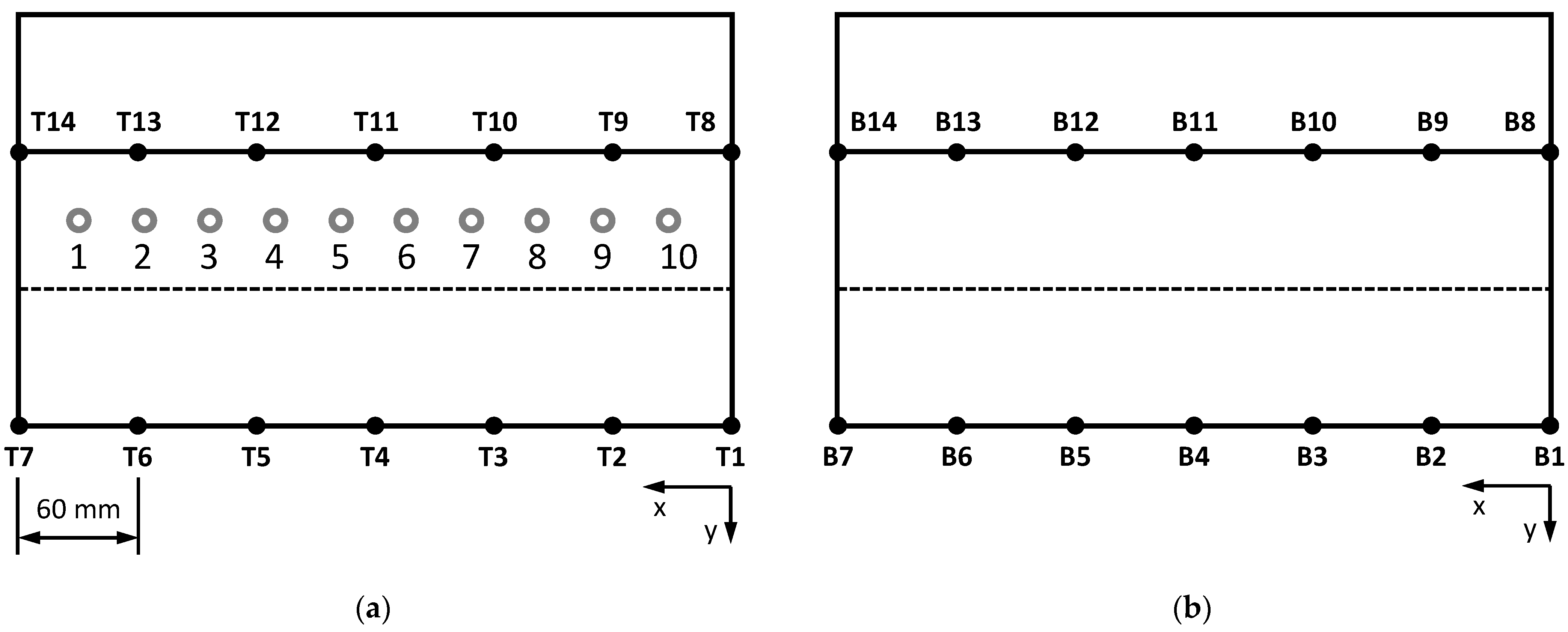
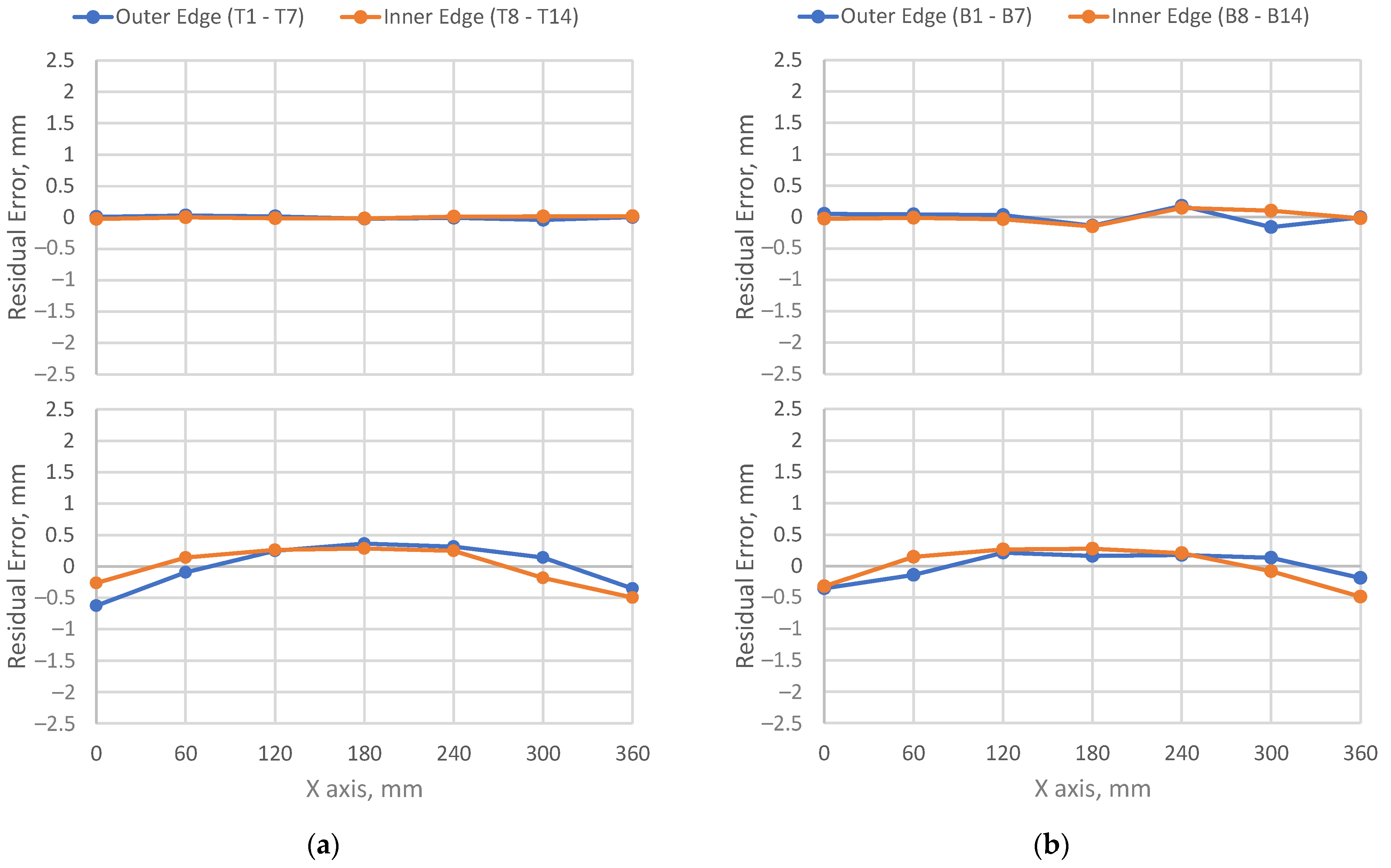
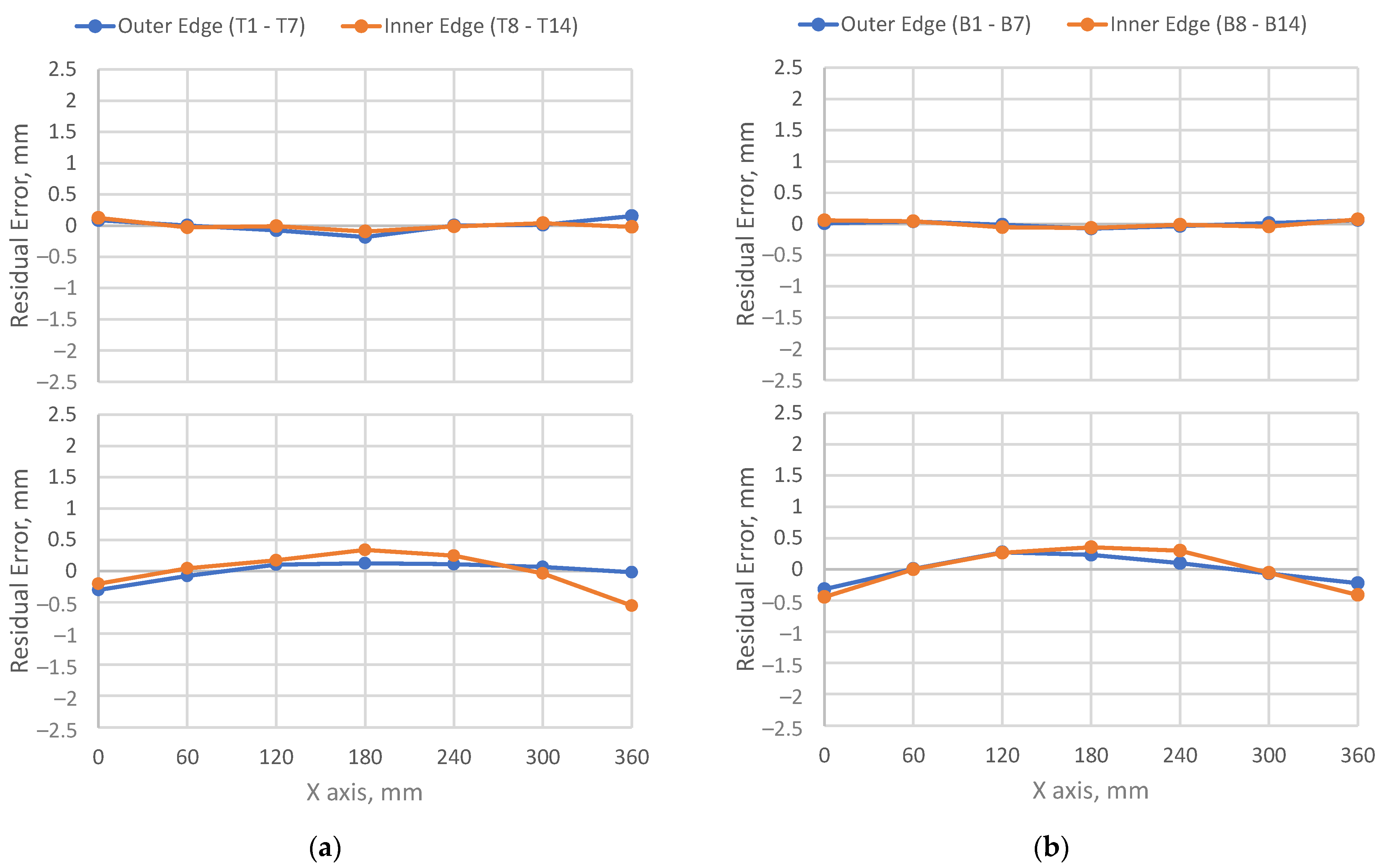
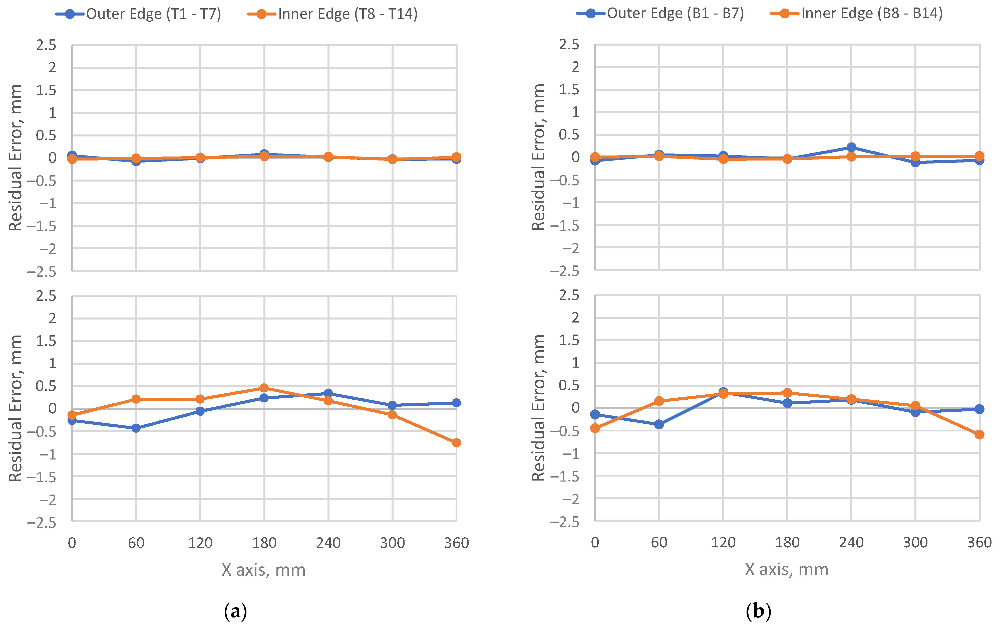
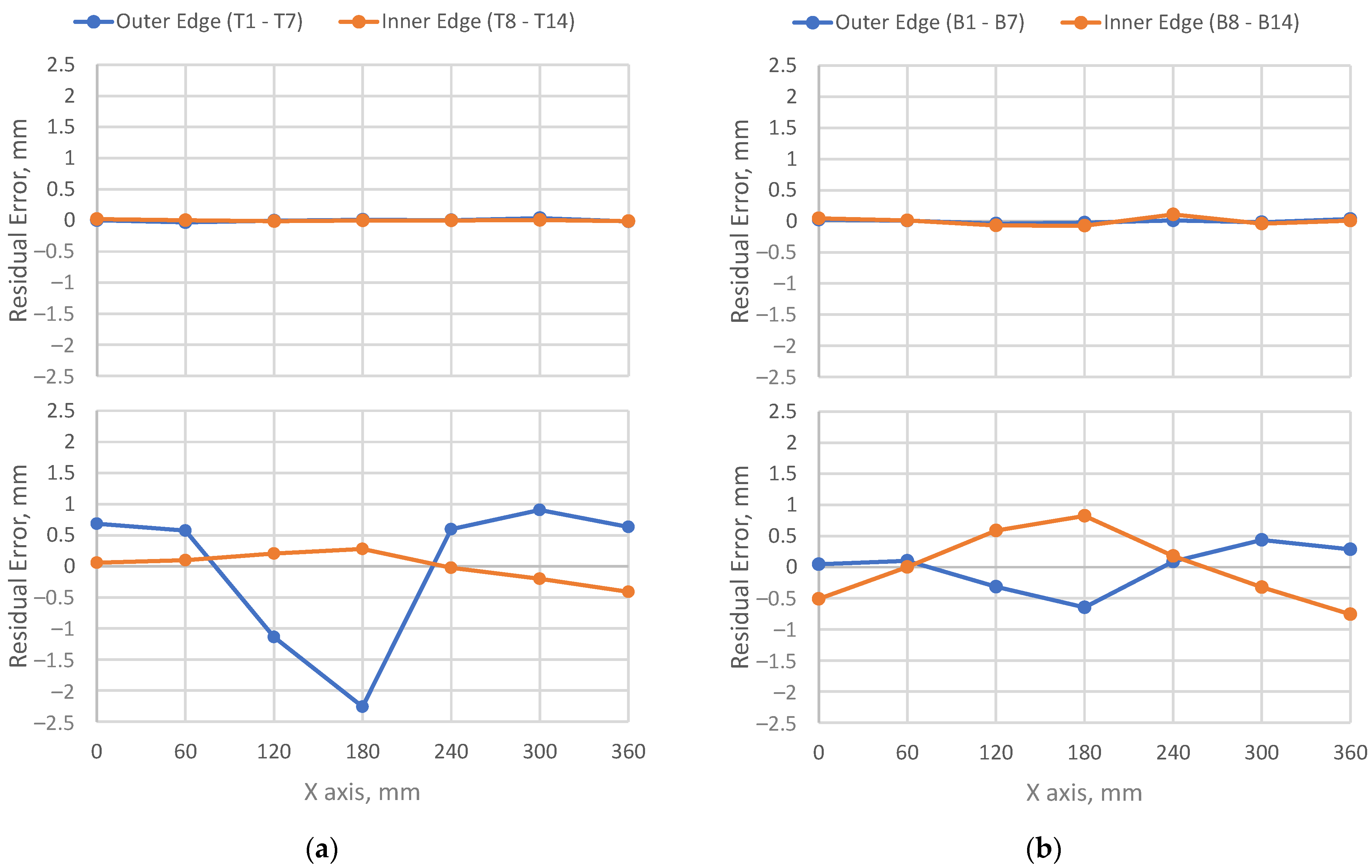
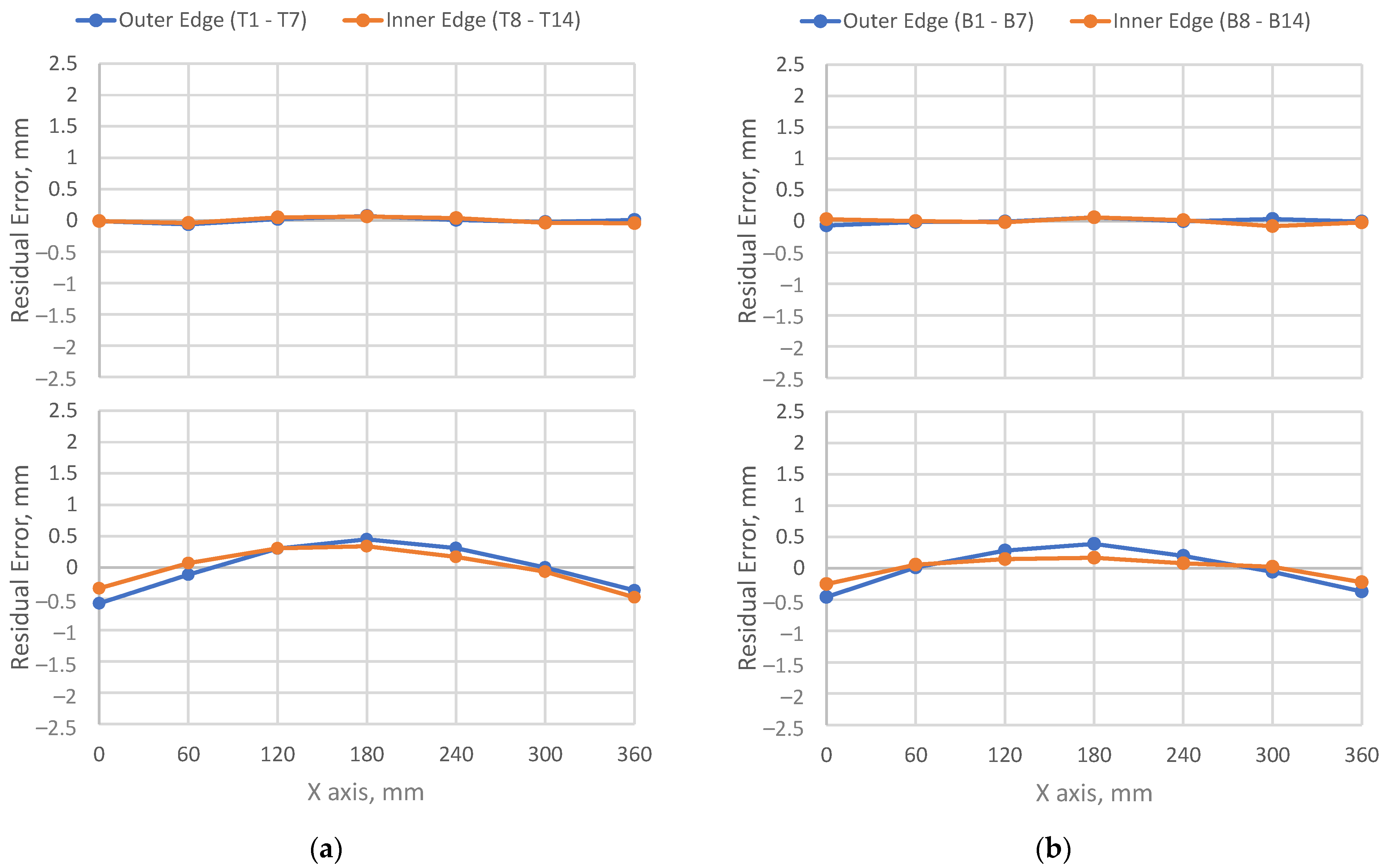
2.2. Metrology of Sheet Metal Distortion

Sheet metal may exhibit a deviation from the ideal flatness due to distortion. The distortion may stem from the manufacturing processes or any exposures to excess external loads or extreme temperatures. This study used a UR-10e collaborative robot with a 3D vision system, as shown in Figure 1a, for the metrology of sheet metal distortion. The 3D vision system is a SICK Ranger 3D vision system that can detect 3D geometric profiles through its high accuracy, high resolution camera. The robot is used to move the 3D vision system over the area of interest for scanning.
A panel consists of the top sheet and the bottom sheet, which are referred to as panel pieces. The panel pieces were prepared according to the panel configuration in Figure 2. Figure 4 depicts the evenly spaced arrangements of the top sheet edge points and the bottom sheet edge points. These edge points were selected for the sheet metal distortion study. The top sheet edge points include the outer edge points from T1 to T7 and the inner edge points from T8 to T14; these edge points are on the edge of the top exterior surface. The bottom sheet edge points include the outer edge points from B1 to B7 and the inner edge points from B8 to B14; these edge points are on the edge of the bottom exterior surface. The edge-point spacing is 60 mm. These edge points were measured with the robotic 3D vision system before and after joining the panel pieces with a specified RFSSW sequence. The robotic 3D vision system setup is shown in Figure 1a, where a panel piece is on a flat table in gravitational equilibrium along with a calibration block.
The measured edge points of a panel piece were used to estimate a plane using the least squares method [31]. The residual error of an edge point is a deviation from the least squares plane. In other words, it is a deviation from the ideal flatness of the panel piece. It was assumed that the residual errors of the edge points represent the distortion of the panel piece. The distortions of each panel piece were measured and evaluated before RFSSW and after RFSSW.
Equation (1) defines the Cartesian coordinates of the measured edge points associated with a panel piece. P i is a spatial point with the Cartesian coordinates of x i , y i , and z i . The Cartesian coordinate system is depicted in the lower right corner of Figure 4. n is the total number of measured points. i is the index of a point. In this case, n is 14 as there are 7 inner edge points and 7 outer edge points for a panel piece as shown in Figure 4.
P i = [ x i y i z i ] 3 × 1 , i =   1 ,   , n , n
Ideally, these measured edge points must belong to a plane if the panel piece is perfectly flat. However, they exhibit deviations from a plane to reflect the true distortion of the panel piece. In Equation (2), x i , y i , and z i are the Cartesian coordinates of P i that is a measured edge point. i is the index of a point. a , b , and c are the plane equation parameters that need to be estimated using the least squares method. e i is the residual error of P i , which also needs to be estimated using the least squares method.
z i = a x i + b y i + c + e i , i = 1 , , n , n
Equation (3) is the matrix form of the plane equation in Equation (2). Equation (4) describes the matrices used in Equation (3). Equation (5) is derived from Equation (3) to define the matrix of residual errors.
Z = M K + E
Z = [ z 1 z 2 z n ] n × 1 , M = [ x 1 y 1 1 x 2 y 2 1 x n y n 1 ] n × 3 ,       K = [ a b c ] 3 × 1 ,       E = [ e 1 e 2 e n ] n × 1
E = Z M K
Equation (6) presents the error function used for the least squares estimation. It is the sum of the residual error squares derived from Equation (5). The least squares estimation aims to find the plane equation parameters that minimize the error function.
ε ( K ) = E T E = ( Z M K ) T ( Z M K )
Therefore, the partial derivatives of the error function with respect to the plane equation parameters must be equal to zero as written in Equation (7).
ε K = 2 M T Z + 2 M T M K = 0
After solving Equation (7) for the plane equation parameters, the estimations of the plane equation parameters become the formula in Equation (8).
K ^ = [ a ^ b ^ c ^ ] = ( M T M ) 1 M T Z
Finally, the parameter estimations from Equation (8) are used to estimate the residual errors of the measured edge points as written in Equation (9).
e ^ i = z i a ^ x i b ^ y i c ^ , i = 1 , , n , n
The estimated residual error of an edge point is a deviation from the least squares plane. In this study, it is assumed that the estimated residual errors of a panel piece represent the panel piece distortion. Furthermore, the estimated residual errors of a panel piece can be summarized with a root-mean-square (RMS) error as written in Equation (10).
e ^ R M S = i = 1 n e ^ i 2 / n i = 1 , , n , n
A root-mean-square error summarizes the distortion of a panel piece. In this study, the distortions of each panel piece were measured and estimated before and after joining the panel pieces with a specified RFSSW sequence.

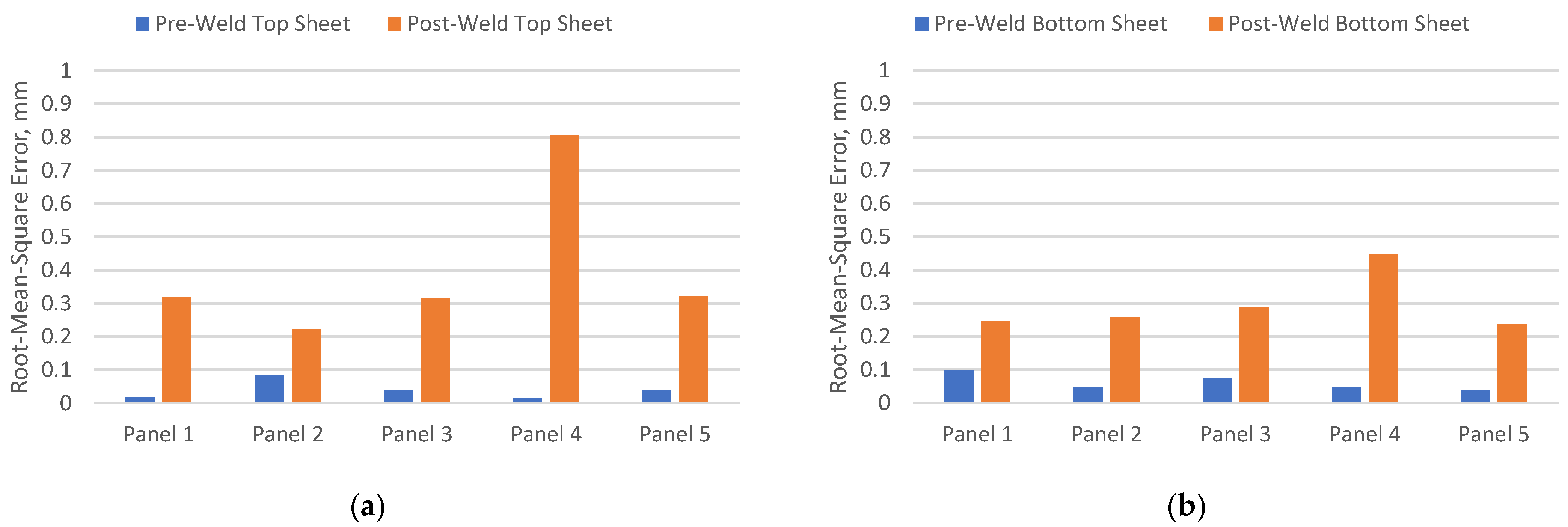
3. Results and Discussion

The RFSSW process produces three distinct weld zones in the workpiece, which are a heat affected zone (HAZ), a thermo-mechanically affected zone (TMAZ), and a stir zone. The HAZ is a region in the heat-treatable base metal that spans around the weld as its outermost shell. It is affected by the process heat but not the mechanical stirring. The TMAZ is an interlayer shell between the HAZ and the stir zone. It is affected by the process heat as well as the mechanical stirring involved in the stir zone. The stir zone is the core of the weld where the tool forges and stirs the plasticized material together during the welding process. It experiences the greatest heat and plastic deformation that induce significant grain refinement and re-precipitation. The size of the stir zone is defined by the diameter of the welding tool and its plunge depth. The metal grain size usually coarsens in the TMAZ and HAZ, but the grain size becomes fine and equiaxed in the stir zone due to dissolution and re-precipitation [7,13,14,15,16]. The thermomechanical processing of RFSSW and the microstructure evolution might create residual stresses that lead to distortion or warping of the panel pieces. Microstructure evolution is a heterogenous kinetic process, which aims towards the thermodynamically equilibrium states via reducing the free energies of formation [32].
Moreover, the HAZ size of RFSSW is a major factor in establishing design requirements for the spot weld spacing and the edge margin. If the HAZ of a spot weld overlaps the edge of the workpiece, edge bulging may happen during the RFSSW process [17]. If the HAZs of nearby refill spot welds overlap each other, the mechanical strength of the assembly may become weaker [17]. Such HAZ overlaps can be prevented by a spot weld spacing of at least four times greater than the spot weld diameter and an edge margin of at least two times greater than the spot weld diameter [17]. Therefore, the panels of this study employed these design requirements to avoid any HAZ-and-HAZ or HAZ-and-the-panel-edge overlaps that may make the panel piece distortion worse.
This experiential study produced five panels with five RFSSW sequences as listed in Table 2. The top/bottom views of the five panels are shown in Figure 5. The panel pieces were prepared in accordance with the panel configuration in Figure 2. Each panel piece was individually scanned using the robotic metrology system before RFSSW and after RFSSW as shown in Figure 1a.
Based on visual observations, all panel pieces exhibited minimal distortions before RFSSW. In other words, they were almost flat. After RFSSW, Panel 4 exhibited the largest distortion with a twist. Panel 3 exhibited minor distortion with a slight twist that is almost unnoticeable in Figure 5. Likewise, Panel 1, Panel 2, and Panel 5 exhibited minor arch-shaped distortions that are almost unnoticeable in Figure 5.
Figure 4 depicts a panel with evenly spaced edge points for metrology. The measured edge points of each panel piece were used to estimate the least squares plane of the panel piece. Afterwards, the residual error of every edge point was estimated with the least squares method. It was assumed that the residual errors of the panel piece edge points represent the distortion of the panel piece. Each panel piece was measured and evaluated before RFSSW and after RFSSW.
The residual errors in Figure 6, Figure 7, Figure 8, Figure 9 and Figure 10 are in good agreement with the visual observations. The X axis is indicated in Figure 4 and Figure 5. The residual errors of the panel piece edge points represent the deviations from the ideal flatness of the panel piece. The outer edge points of the top sheet are labeled as T1–T7, and the inner edge points are T8–T14. The outer edge points of the bottom sheet are labeled as B1–B7, and the inner edge points are B8–B14.
Before RFSSW, all panel pieces had residual errors within +/−0.20 mm according to Figure 6, Figure 7, Figure 8, Figure 9 and Figure 10, which dictate that all panel pieces were almost flat. Nonetheless, the bottom sheet of Panel 1, the top sheet of Panel 2, and the bottom sheet of Panel 3 exhibited slight deviations from the ideal flatness before RFSSW according to Figure 6, Figure 7 and Figure 8.
After RFSSW, the residual errors of the Panel 4 edge points imply that Panel 4 had noticeable warpage according to Figure 9. However, the residual errors of Panel 1, Panel 2, and Panel 5 imply slight arch-shaped distortions according to Figure 6, Figure 7, and Figure 10, respectively, whereas the residual errors of the inner and outer edge points both exhibit similar arch-shaped patterns. However, the residual errors of Panel 3 indicate a slight twist according to Figure 8.
Figure 11 presents the root-mean-square errors of the residual errors that summarize the distortion of each panel piece before RFSSW and after RFSSW. The formula of the root-mean-square error is in Equation (10). According to Figure 11, all pre-weld panel pieces exhibit root-mean-square errors less than 0.10 mm, and all post-weld panel pieces exhibit root-mean-square errors less than 0.90 mm. The RFSSW sequence of Panel 4 demonstrates the worst distortion with a top sheet root-mean-square error of 0.80 mm and a bottom sheet root-mean-square error of 0.44 mm. The rest of the RFSSW sequences demonstrate much less distortion with top sheet root-mean-square errors of less than 0.40 mm and bottom sheet root-mean-square errors of less than 0.30 mm. Especially, the RFSSW sequence of Panel 2 exhibits the least distortion with a top sheet root-mean-square error of 0.22 mm and a bottom sheet root-mean-square error of 0.26 mm. These results are in good agreement with the visual observations of the panels in Figure 5.
The panel pieces thermally expand during each RFSSW process and contract during the subsequent cooldown period. The stirring actions of the welding tool impose more stresses on the top sheet of the panel during the welding process since the welding process is performed from the top sheet side. This means that more thermal expansion and contraction occur in the top sheet than in the bottom sheet during and after the RFSSW process. In addition, the panel pieces are two dissimilar aluminum alloys with different thicknesses, which are the 2 mm thick AA6013-T6 top sheet and the 3 mm thick AA2029-T8 bottom sheet. They expand and contract differently during and after the RFSSW process. All of these RFSSW phenomena may contribute to the formations of distortion and residual stresses in the panel pieces. Therefore, a proper RFSSW sequence is necessary to achieve minimal distortion and residual stresses in a multi-spot-weld panel.
The results suggest that the RFSSW sequence of Panel 4 exhibits the worst distortion. The RFSSW sequence of Panel 4 extensively involves new spot welds being produced in between existing spot welds. Perhaps, the space between the existing spot welds serves as a “nest” that accumulates the distortions and residual stresses that resulted from new spot welds produced within the “nest”. It is most likely that the existing spot welds act like locking mechanisms to keep the thermal expansion/contraction of the panel pieces within the “nest”. The RFSSW sequence of Panel 4 involves the largest “nest” between the Spot-1 and Spot-10 welds with a center-to-center spacing of 324 mm (9 × 36 mm). The remaining eight spot welds all go in between the Spot-1 and Spot-10 welds via snowballing the panel piece distortions and residual stresses within the “nest”. Therefore, Panel 4, perhaps, exhibits the worst distortion. The other panels do not involve such large “nests” according to their RFSSW sequences. The RFSSW sequences of Panel 1 and Panel 5 do not even involve such “nested” successions. The RFSSW sequence of Panel 2 involves small “nests”, whereas each “nest” accommodates up to one spot weld. The RFSSW sequence of Panel 3 also involves small “nests”, whereas each “nest” accommodates up to two spot welds. Therefore, these panels, perhaps, exhibit less distortions than Panel 4. In fact, Panel 2 exhibits the least distortion among the five panels. These are empirical results that need validation with the finite element analysis method in the future.
This work highlights the effects of RFSSW sequences on sheet metal distortion and demonstrates that RFSSW sequences indeed produce different levels of sheet metal distortion. It is not possible to demonstrate this relationship without the proposed metrology method for measuring and estimating sheet metal distortion.
Sheet metals are widely used in aircraft structures, automotive bodies, vessel assemblies, civil structures, and commercial or consumer products. As RFSSW offers an outstanding ability to join aluminum alloys, the research findings of this work would significantly benefit industrial applications that use RFSSW to join sheet metals of similar or dissimilar aluminum alloys into assemblies with minimal shape distortion. Based on the results, it is assumed that producing too many successive spot welds in between existing spot welds would intensify the distortions of the panel pieces as the existing spot welds may act like locking mechanisms that accumulate distortions and residual stresses.

4. Conclusions

This study successfully demonstrated the use of the robotic metrology system and the least squares method to measure and estimate the flatness of sheet metal. This new capability was instrumental in studying the effects of RFSSW sequences on sheet metal distortion. The experiential study produced five 10-spot-weld panels with five different RFSSW sequences, whereas the RFSSW sequences were based on common practice of making sheet metal assemblies. A panel consisted of the top sheet, a 2 mm thick AA6013-T6 sheet, and the bottom sheet, a 3 mm thick AA2029-T8 sheet. The five panels exhibited comparable distortions except Panel 4. The RFSSW sequence of Panel 4 exhibited the worst distortion with a top sheet root-mean-square error of 0.80 mm and a bottom sheet root-mean-square error of 0.44 mm. The rest of the RFSSW sequences exhibited much less distortions with top sheet root-mean-square errors of less than 0.40 mm and bottom sheet root-mean-square errors of less than 0.30 mm. Especially, the RFSSW sequence of Panel 2 exhibited the least distortion with a top sheet root-mean-square error of 0.22 mm and a bottom sheet root-mean-square error of 0.26 mm. Based on the results, it is assumed that producing too many successive spot welds in between existing spot welds would intensify the distortions of the panel pieces as the existing spot welds may act like locking mechanisms that accumulate distortions and residual stresses.
The least squares method estimated the panel piece deviations from the ideal flatness before RFSSW and after RFSSW. It focused on the flatness of the panel pieces. Estimating sheet metal distortions in all directions can be a potential topic for future work. Moreover, the outcomes of this research can be validated or advanced with new workpiece materials, welding tools, welding parameters, and thermal management techniques in the future. An important topic for future work can be the finite element modeling and simulation of the residual stresses and distortion produced by RFSSW.

Author Contributions

Conceptualization, E.B.; methodology, E.B.; software, E.B. and M.M.; validation, E.B. and M.M.; formal analysis, E.B.; investigation, E.B., M.M., S.F., M.F. and K.K.; resources, E.B., M.M., S.F., M.F. and K.K.; data curation, E.B.; writing—original draft preparation, E.B.; writing—review and editing, M.M., S.F., M.F. and K.K.; visualization, E.B.; supervision, E.B.; project administration, E.B.; funding acquisition, M.F., S.F., K.K. and E.B. All authors have read and agreed to the published version of the manuscript.

Funding

This research was funded by Kawasaki Heavy Industries, Inc. through the Center for Friction Stir Processing. The aluminum sheets and the application specifications were provided by The Boeing Company through the Center for Friction Stir Processing.

Data Availability Statement

The data presented in this study are available on request from the corresponding author. The data sets are not publicly available due to their complex structure.

Acknowledgments

The authors express gratitude to the National Institute for Aviation Research (NIAR) at Wichita State University for administrative and technical support.

Conflicts of Interest

The authors declare no conflict of interest.

References

  1. Shen, Z.; Ding, Y.; Gerlich, A.P. Advances in friction stir spot welding. Crit. Rev. Solid State Mater. Sci. 2020, 45, 457–534. [Google Scholar] [CrossRef]
  2. Schilling, C.; Dos Santos, J. Method and Device for Linking at Least Two Adjoining Work Pieces by Friction Welding. U.S. Patent 6,722,556, 20 April 2004. [Google Scholar]
  3. Okada, H.; Kamimuki, K.; Yoshikawa, S.; Fukada, S. Refill Friction Spot Joining for Aerospace Application; SAE Technical Paper 2015-01-2614; SAE: Warrendale, PA, USA, 2015. [Google Scholar] [CrossRef]
  4. Hovanski, Y.; Hunt, J.; Larsen, B. Refill Friction Stir Spot Welding using a Super Abrasive Tool. U.S. Patent Application No. 17/436,915, 12 May 2022. [Google Scholar]
  5. Oberembt, C.; Allen, C.; Arbegast, W.; Patnaik, A. Screening for process variable sensitivity in refill friction spot welding of 6061 aluminium sheet. In Friction Stir Welding and Processing IV; Mishra, R.S., Mahoney, M.W., Lienert, T.J., Jata, K.V., Eds.; John Wiley & Sons: New York, NY, USA, 2007; pp. 359–368. [Google Scholar]
  6. Shen, Z.; Yang, X.; Zhang, Z.; Cui, L.; Li, T. Microstructure and failure mechanisms of refill friction stir spot welded 7075-T6 aluminum alloy joints. Mater. Des. 2013, 44, 476–486. [Google Scholar] [CrossRef]
  7. Reimann, M.; Goebel, J.; dos Santos, J.F. Microstructure Evolution and Mechanical Properties of Keyhole Repair Welds in AA 2219-T851 Using Refill Friction Stir Spot Welding. J. Mater. Eng. Perform. 2018, 27, 5220–5226. [Google Scholar] [CrossRef]
  8. De Castro, C.C.; Plaine, A.H.; Dias, G.P.; de Alcântara, N.G.; dos Santos, J.F. Investigation of geometrical features on me-chanical properties of AA2198 refill friction stir spot welds. J. Manufact. Proc. 2018, 36, 330–339. [Google Scholar] [CrossRef]
  9. Patnaik, A.; Koch, K.; Arbegast, W.; Allen, C. Static Properties of “Refill” Friction Spot Welded Skin Stiffened Compression Panels; SAE Technical Paper 2006-01-0967; SAE: Warrendale, PA, USA, 2006. [Google Scholar] [CrossRef]
  10. Muci-Küchler, K.H.; Kalagara, S.; Arbegast, W.J. Simulation of a Refill Friction Stir Spot Welding Process Using a Fully Coupled Thermo-Mechanical FEM Model. J. Manuf. Sci. Eng. 2010, 132, 014503. [Google Scholar] [CrossRef]
  11. Lacki, P.; Derlatka, A. Strength evaluation of beam made of the aluminum 6061-T6 and titanium grade 5 alloys sheets joined by RFSSW and RSW. Compos. Struct. 2017, 159, 491–497. [Google Scholar] [CrossRef]
  12. Berger, E.; Miles, M.; Curtis, A.; Blackhurst, P.; Hovanski, Y. 2D Axisymmetric Modeling of Refill Friction Stir Spot Welding and Experimental Validation. J. Manuf. Mater. Process. 2022, 6, 89. [Google Scholar] [CrossRef]
  13. Okada, H.; Kamimuki, K.; Fujimoto, M. Assembly Study of Refill FSSW. SAE Int. J. Aerosp. 2013, 6, 299–304. [Google Scholar] [CrossRef]
  14. Fukada, S.; Ohashi, R.; Fujimoto, M.; Okada, H. Refill friction stir spot welding of dissimilar materials consisting of A6061 and hot dip zinc-coated steel sheets. In Proceedings of the 201st International Joint Symposium on Joining and Welding3, Osaka, Japan, 6–8 November 2013; pp. 183–187. [Google Scholar] [CrossRef]
  15. Boldsaikhan, E.; Fukada, S.; Fujimoto, M.; Kamimuki, K.; Okada, H.; Duncan, B.; Bui, P.; Yeshiambel, M.; Brown, B.; Handyside, A. Refill Friction Stir Spot Joining Rivet Replacement Technology; SAE Technical Paper 2016-01-2130; SAE: Warrendale, PA, USA, 2016. [Google Scholar] [CrossRef]
  16. Boldsaikhan, E.; Fukada, S.; Fujimoto, M.; Kamimuki, K.; Okada, H. Refill friction stir spot welding of surface-treated aerospace aluminum alloys with faying-surface sealant. J. Manuf. Process. 2019, 42, 113–120. [Google Scholar] [CrossRef]
  17. Balasubramaniam, G.L.; Boldsaikhan, E.; Fukada, S.; Fujimoto, M.; Kamimuki, K. Effects of Refill Friction Stir Spot Weld Spacing and Edge Margin on Mechanical Properties of Multi-Spot-Welded Panels. J. Manuf. Mater. Process. 2020, 4, 55. [Google Scholar] [CrossRef]
  18. Balasubramaniam, G.L.; Boldsaikhan, E.; Rosario, G.F.J.; Ravichandran, S.P.; Fukada, S.; Fujimoto, M.; Kamimuki, K. Mechanical Properties and Failure Mechanisms of Refill Friction Stir Spot Welds. J. Manuf. Mater. Process. 2021, 5, 118. [Google Scholar] [CrossRef]
  19. Ravichandran, S.P. Comparison of refill friction stir spot welding versus riveting in aircraft applications. Master’s Thesis, Wichita State University, Wichita, KS, USA, 2019. [Google Scholar]
  20. Joseph Rosario, G.F. Static test simulation of refill friction stir spot welded and riveted coupons using finite element analysis. Master’s Thesis, Wichita State University, Wichita, KS, USA, 2019. [Google Scholar]
  21. Madras Karunamurthy, S.K. Distortion of refill friction stir spot welding. Master’s Thesis, Wichita State University, Wichita, KS, USA, 2020. [Google Scholar]
  22. Lakshmi Balasubramaniam, G. Robotic Refill Friction Stir Spot Welding for Aerospace Applications. Ph.D. Thesis, Wichita State University, Wichita, KS, USA, 2021. [Google Scholar]
  23. Kubit, A.; Trzepiecinski, T. A fully coupled thermo-mechanical numerical modelling of the refill friction stir spot welding process in Alclad 7075-T6 aluminium alloy sheets. Arch. Civ. Mech. Eng. 2020, 20, 1–14. [Google Scholar] [CrossRef]
  24. Kluz, R.; Kubit, A.; Trzepiecinski, T.; Faes, K. Polyoptimisation of the refill friction stir spot welding parameters applied in joining 7075-T6 Alclad aluminium alloy sheets used in aircraft components. Int. J. Adv. Manuf. Technol. 2019, 103, 3443–3457. [Google Scholar] [CrossRef] [Green Version]
  25. Kluz, R.; Kubit, A.; Trzepiecinski, T.; Faes, K.; Bochnowski, W. A Weighting Grade-Based Optimization Method for Determining Refill Friction Stir Spot Welding Process Parameters. J. Mater. Eng. Perform. 2019, 28, 6471–6482. [Google Scholar] [CrossRef] [Green Version]
  26. Korbel, A. Effect of aircraft rivet installation process and production variables on residual stress, clamping force and fatigue behaviour of thin sheet riveted lap joints. Thin Walled Struct. 2022, 181, 110041. [Google Scholar] [CrossRef]
  27. Liang, Q.; Zhang, T.; Zhu, C.; Bi, Y. Effect of Riveting Angle and Direction on Fatigue Performance of Riveted Lap Joints. Coatings 2021, 11, 236. [Google Scholar] [CrossRef]
  28. Tabar, R.S.; Wärmefjord, K.; Söderberg, R. Rapid sequence optimization of spot welds for improved geometrical quality using a novel stepwise algorithm. Eng. Optim. 2020, 53, 867–884. [Google Scholar] [CrossRef]
  29. Tabar, R.S.; Lindkvist, L.; Wärmefjord, K.; Söderberg, R. Efficient Joining Sequence Variation Analysis of Stochastic Batch Assemblies. J. Comput. Inf. Sci. Eng. 2022, 22, 1–10. [Google Scholar] [CrossRef]
  30. MMPDS. MMPDS-14 Metallic Materials Properties Development and Standardization (MMPDS) Handbook; Battelle Memorial Institute: Columbus, OH, USA, 2020. [Google Scholar]
  31. Boldsaikhan, E. Measuring and Estimating Rotary Joint Axes of an Articulated Robot. IEEE Trans. Instrum. Meas. 2020, 69, 8279–8287. [Google Scholar] [CrossRef]
  32. Chen, L.-Q. Phase-Field Models for Microstructure Evolution. Annu. Rev. Mater. Res. 2002, 32, 113–140. [Google Scholar] [CrossRef] [Green Version]
Figure 1. This figure depicts the robotic systems for metrology and refill friction stir spot welding (RFSSW): (a) A UR-10e collaborative robot with a 3D vision system is for metrology; (b) A Kawasaki RFSSW robot with an RFSSW end effector is for welding; (c) The close-by view of the RFSSW end effector emphasizes the RFSSW tool, the opposing anvil, and the C-shaped frame.
Jmmp 07 00109 g001
Figure 2. The panel configuration is depicted in the side view drawing, left, and the top view drawing, right. A panel consists of a 2 mm thick top sheet welded onto a 3 mm thick bottom sheet with 10 refill spot welds. Refill spot welds are the circles in the top view drawing. The spot weld diameter is 9 mm, the spot weld spacing is 36 mm, and the edge margin is 18 mm. The aspect ratio is not proportional to emphasize the details.
Jmmp 07 00109 g002
Figure 3. The panel clamping configuration for welding is depicted in the side view drawing, left, and the top view drawing, right. The bottom sheet as well as the top sheet are clamped firmly between an anvil bar and a rigid clamping bar using two C-clamps with a gripping force of approximately 800 N (180 lbf) at the furthest ends of the gripping bars. The spot-weld spots are labeled from 1 to 10. The aspect ratio is not proportional to emphasize the details.
Jmmp 07 00109 g003
Figure 4. This figure depicts the evenly spaced panel piece edge points for distortion metrology: (a) The top sheet edge points are the outer edge points from T1 to T7 and the inner edge points from T8 to T14, whereas these edge points are on the edge of the top exterior surface; (b) The bottom sheet edge points are the outer edge points from B1 to B7 and the inner edge points from B8 to B14, whereas these edge points are on the edge of the bottom exterior surface. The aspect ratio is not proportional to emphasize the details.
Jmmp 07 00109 g004
Figure 5. This figure depicts the welded panels with different spot-welding sequences: (a) The left column shows the top views of Panel 1, Panel 2, Panel 3, Panel 4, and Panel 5, respectively; (b) The right column shows the bottom views of Panel 1, Panel 2, Panel 3, Panel 4, and Panel 5, respectively.
Jmmp 07 00109 g005
Figure 6. These edge-point residual errors signify the Panel 1 distortion: (a) The left column shows the pre/post-weld residual errors of the top sheet; (b) The right column shows the pre/post-weld residual errors of the bottom sheet. The pre-weld residual errors are in the upper row.
Jmmp 07 00109 g006
Figure 7. These edge-point residual errors signify the Panel 2 distortion: (a) The left column shows the pre/post-weld residual errors of the top sheet; (b) The right column shows the pre/post-weld residual errors of the bottom sheet. The pre-weld residual errors are in the upper row.
Jmmp 07 00109 g007
Figure 8. These edge-point residual errors signify the Panel 3 distortion: (a) The left column shows the pre/post-weld residual errors of the top sheet; (b) The right column shows the pre/post-weld residual errors of the bottom sheet. The pre-weld residual errors are in the upper row.
Jmmp 07 00109 g008
Figure 9. These edge-point residual errors signify the Panel 4 distortion: (a) The left column shows the pre/post-weld residual errors of the top sheet; (b) The right column shows the pre/post-weld residual errors of the bottom sheet. The pre-weld residual errors are in the upper row.
Jmmp 07 00109 g009
Figure 10. These edge-point residual errors signify the Panel 5 distortion: (a) The left column shows the pre/post-weld residual errors of the top sheet; (b) The right column shows the pre/post-weld residual errors of the bottom sheet. The pre-weld residual errors are in the upper row.
Jmmp 07 00109 g010
Figure 11. The root-mean-square errors of the residual errors signify the overall distortions of the pre/post-weld sheet metals: (a) The left graph shows a comparison between the pre/post-weld top sheet distortions of the panels; (b) The right graph shows a comparison between the pre/post-weld bottom sheet distortions of the panels.
Jmmp 07 00109 g011
Table 1. Mechanical Properties of the 6013-T6 and 2029-T8 Aluminum Alloys.
AA6013-T6 (Top Sheet)AA2029-T8 (Bottom Sheet)
Ultimate Strength378 MPa439 MPa
Yield Strength300 MPa410 MPa
Elongation8%8%
Table 2. Panels and RFSSW Sequences.
PanelsRFSSW Sequences for Spots in Figure 3
Panel 1 1 2 3 4 5 6 7 8 9 10
Panel 2 1 3 5 7 9 2 4 6 8 10
Panel 3 1 4 7 10 2 5 8 3 6 9
Panel 4 1 10 2 9 3 8 4 7 5 6
Panel 5 5 6 4 7 3 8 2 9 1 10
Table 3. Optimum RFSSW Parameter Settings.
RFSSW Process ParametersOptimum Settings
Shoulder Plunge Depth2.4 mm
Probe Speed6 mm/s
Tool Spindle Speed1800 r/min
Disclaimer/Publisher’s Note: The statements, opinions and data contained in all publications are solely those of the individual author(s) and contributor(s) and not of MDPI and/or the editor(s). MDPI and/or the editor(s) disclaim responsibility for any injury to people or property resulting from any ideas, methods, instructions or products referred to in the content.

