1. Introduction
Design data are created and maintained across industries in various computer-aided design (CAD) systems and formats. Various types of CAD systems are used for designing parts. Throughout a product’s lifecycle, CAD files store various types of product information such as geometrical dimensions and tolerances [
1]. Design data play an important role during the manufacturing of the product. Design data provide insights and milestones during manufacturing [
2].
The modern manufacturing industry relies heavily on concurrent manufacturing [
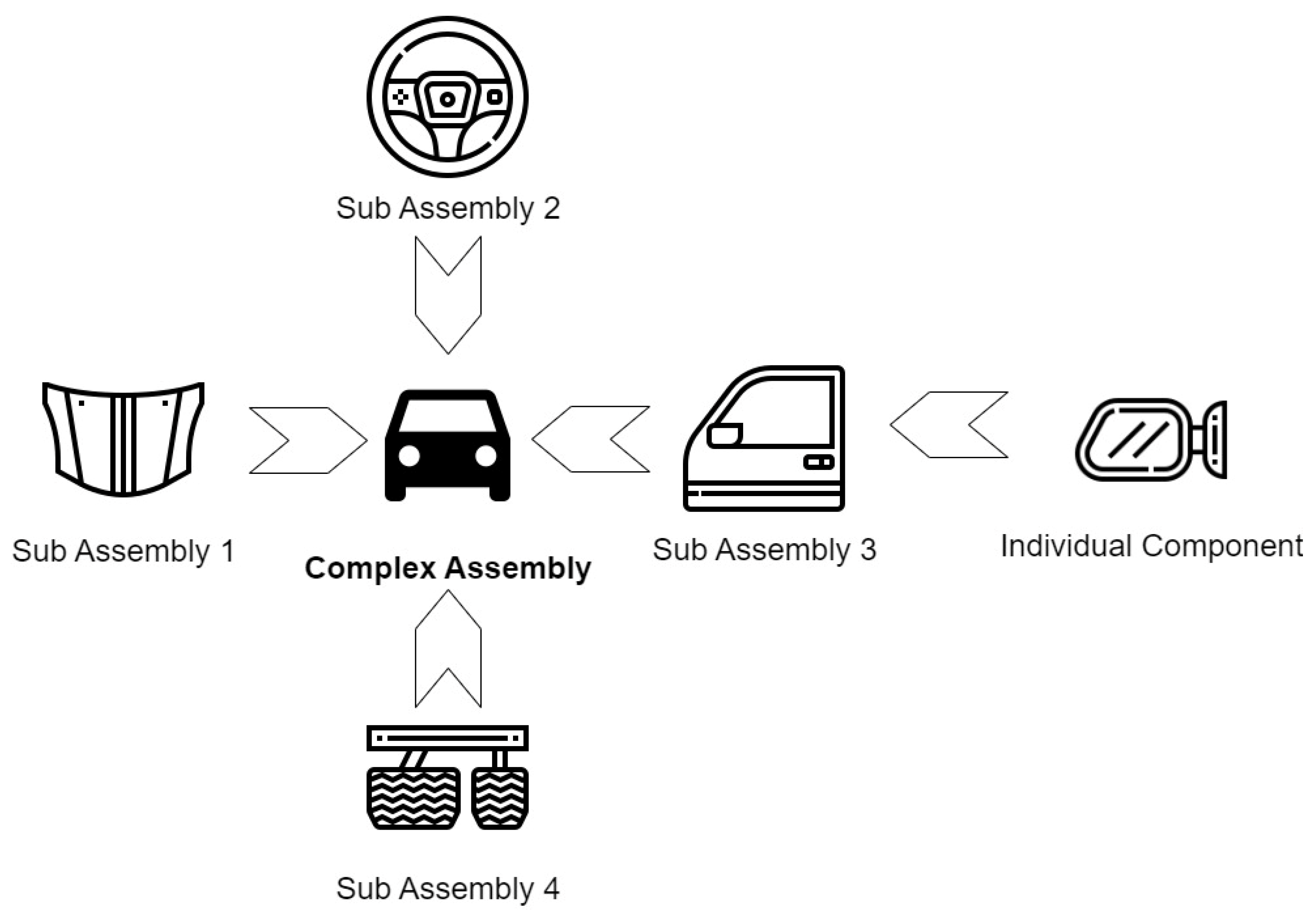
3]. Complex products are often manufactured in pieces, from around the globe. Various levels of manufacturing participants contribute to such products. As shown in
Figure 1, low-level individual parts are manufactured from sheet metal or bar metal, and such individual parts are assembled to form subassemblies, and such subassemblies are assembled further to manufacture the useful product. As the levels in collaborative manufacturing increase, the complexity of the process tends to increase. Each level has restricted mobility in terms of design, production rate, and cost for manufacturing because the output at each level output could be input to the next level, and changes in any design can hamper further assemblies. Hence, engineering change management plays an important and critical role in cost and time to market. Usually, the lower-level participants are small industries, and they are often resource-strapped. The procurement initiated by larger companies and the communication for this procurement is still human-centric. Often, after manual verification of the part design, the awarding of a subcontract, scheduling, and sequencing are performed. This makes procurement highly human-intervention-dependent, leading to many current challenges in real supply chains.
Due to market competition, organizations are often reluctant to share their valuable data with other industries, suppliers, and subsuppliers. However, a need for a common information pool is equally important for small manufacturing businesses that are the backbones of larger organizations. Small businesses stimulate parallel manufacturing and bring down the time to market along with cost. Small businesses are often the drivers of the manufacturing process. Due to insecurity in data sharing, small-scale manufacturers cannot connect with large organizations, restricting the business expansion of small industries. On other hand, large-scale manufacturers often experience a shortage of proper capacity for manufacturing specialized or customized components for their assemblies. This can result in larger lead times and costs by relying only on known suppliers (only those with prior history). Manufacturing democratization allows for larger manufacturers to communicate with a wider set of suppliers.
This has increased the data-sharing aspects between the different manufacturers. CAD files are the primary source for sharing part design data between different elements of the manufacturing ecosystem. Sharing design data entertains many challenges, such as data security and the redundancy of the design data. Mainly, the abundance of design data stored in a solid format often stimulates data redundancy. These CAD models are stored and accessed as two-dimensional (2D) or three-dimensional (3D) CAD models. Such CAD models and files often require human interaction to understand the part features and dimensions. The machine readability of such CAD models is being explored, largely for applying cutting-edge predictive modeling and artificial intelligence solutions. Manufacturing democratization necessitates online procurement across longer supply chains. In such cases, the exchange of design data files across companies becomes very important to solicit manufacturing services. This paper proposes a method for extracting the feature information along with the dimensional information of individual data from CAD files and its storage of the interlinked data into a machine-readable format, such as XML files. Such a design- and geometric-data-enriched XML file provides uniformly structured data for detecting patterns using advanced machine learning models. Currently, as discussed in
Section 2, the majority of CAD model processing for advanced predictive models is developed using the CAD model’s point cloud and/or voxel grid methodology. These methods rely heavily on the sampled surface information. Such parse data structures are difficult to process and rely on manufacturing-related information gathering. The main reason is that such methodology ignores tolerancing information and is often seen to oversight the smaller feature information. Therefore, uniform data structures of CAD models are valuable for increasing machine readability for applying advanced predictive modeling in manufacturing domain.
In the presented paper, we have developed a framework for extracting design information from CAD models, including the model’s face information, dimensions, and relationship with other faces. This extracted information is stored into an XML file using an entity-based hierarchical structure to preserve the relational information.
In
Section 2, prior studies and the Standard for the Exchange of Product Data (STEP) file structure is discussed;
Section 3 proposes the method for data extraction from CAD models, and the storage schema is discussed;
Section 4 discusses the application and implemented example along with the results;
Section 5 discusses the conclusion and future studies.
2. Review of Literature Survey
The STEP structure representation of parts is used for recognizing milling features such as slots and corner blind slots from a given part [
4]. The algorithm used in prior work utilizes the interface representation of the part, and features are identified using heuristics. Furthermore, there are a few approaches to recognize rotational part features such as cylindrical holes, conical holes, and cylindrical and conical external features using STEP files [
5,
6]. Work performed in [
7] recognizes assembly features from STEP file structures. The recognition algorithms undertake feature-level information. In these algorithms, the coordinate points are used to identify these features. Complex features composed of complex surfaces can also be detected using curve processing algorithms, especially from B-Spline surfaces [
8]. Moreover, work by [
9] demonstrated feature recognition using clustering-based algorithms from feature information extracted from STEP files. All the same, the generation of the part geometry’s STEP knowledge base plays an important role in understanding the dimensionality of the part. Primarily, the manufacturing machines consider the part’s dimensions to a given machine’s workspace [
10]. This requires the part dimensions of the each-sided feature. The machine workspace should be larger than the given part’s largest dimension. Understanding such crucial information helps in identifying the dimensionality constraints of the parts [
11].
Furthermore, recent work on applying machine learning algorithms in order to perform classification of CAD models by [
12,
13,
14] used mesh models to generate point clouds from the model surface by sampling coordinate points to serve as input for the classification model. This work, along with [
15,
16], used a similar input to process CAD models. In these works, part design failed to consider local manufacturing features based on the sampling size. To best of our knowledge, current work performed in this field does not provide a framework for structuring CAD model data for consumption by machine learning models for various tasks related to manufacturing.
STEP Files
The STEP format is a neutral CAD format that was developed to standardize the exchange of geometric data under the International Organization for Standards (ISO) 10303 format. A STEP file can also be called a part 21 file, as the format comes under ISO 10303-21. The STEP format can be used to share not only geometric data but also product information, which could be used for other components of the system.
The main and most effective advantage of STEP files is that they are machine- and human-readable. To store design data in a logical order, STEP files are organized using a specific format. Understanding the structure of the STEP file is important to develop the algorithm for extracting the dimensions and feature information of the part. Moreover, STEP files are organized using various keywords; these keywords navigate the structure and part information throughout the file body. Broadly, the STEP file is organized in two separate sections [
5]. These sections are explained below.
Header Section: The header section is located at the top (starting) of the STEP file. This section includes metainformation of the part and design file, such as the type of STEP file, filename, and software used to create the drawing. The section begins with the keyword HEADER and ends with ENDSEC.
Data Section: The data section is located under the header section. The data section starts with the keyword DATA and ends with ENDSEC. This section stores part dimensional and geometrical information such as face numbers, edge numbers, coordinate points, and vertex points of each edge. The information in the data section is represented in a linewise manner. Each line encloses certain information, often called an entity, and the type of information is identified using keywords present in each line, called entity type. Each line begins with a line number. The line number starts with 1 and has a prefix as ‘#’. The representation format of the line in the data section is given as follows:
# LINE_NO = ENTITY_TYPE (ENTITY)
The STEP file format contains several predefined entity types, and each entity type has a predefined keyword. These entities and their predefined keywords are explained in the next section. Most types of entities store line numbers of the next consecutive entity type. Some entity types store dimensional information such as coordinate points or geometrical information of edges.
The entities of STEP files hierarchically store the information. Each entity guides information to the next lower entity, and so on, until the node of the hierarchical tree is reached. These nodes store various types of information, but the information of principal interest is coordinate point locations. The part design information is organized arbitrarily throughout the STEP file. This makes it hard and convoluted at first glance. However, the STEP file possesses an underlying structure that leads to the extraction of the geometrical features. This extraction is possible with the help of the tree structure, which is explained in the following section.
The STEP file possesses a hierarchical tree structure for storing design data, and the data are represented in a line-by-line manner. The structure is organized using keywords. These keywords describe the nature of data present in the line in the STEP file. While describing part design in a STEP file, each of these keywords navigates the information of the next hierarchical keyword using the line numbers. These keywords are defined below [
17].
CLOSED_SHELL: A closed shell can be considered a gateway for part design in a STEP file. Every part is given under one closed shell. STEP file divides the part in a facewise section. Each face receives one branch, and it expands further until the vertex point level of each of its edges. The line containing CLOSED_SHELL as a keyword discloses the line numbers of all the ADVANCE_FACEs, which bound the part together.
ADVANCED_FACE: An advanced face is a generic face of a given part. The number of advanced faces depends on the number of faces that enclose the given part. The line with the keyword ADVANCE_FACE contains further line numbers of FACE_OUTER_BOUND/FACE_BOUND. Each advance face contains one face outer bound. Hence, only one line number of the respective face outer bound is given in this line. Moreover, this line also gives surface type information such as “CYLINDER” for circular or curved faces, “PLANE” for planar surfaces, “CONICAL” for conical types of surfaces, and “TOROIDAL” for toroidal surfaces.
FACE_BOUND/FACE_OUTER_BOUND: Face outer bound, or face bound, both disclose the information of edges that develop the respective face. Each face is formed with a loop of edges. The line with the keyword FACE_BOUND navigates to the EDGE_LOOP lines for further travel.
EDGE_LOOP: Each edge loop is created using several edges. The line with the keyword EDGE_LOOP provides the line numbers for all the edges that disclose the represented surface. These edges are shown in a line with the keyword ORIENTED_EDGE.
ORIENTED_EDGE: The line with the keyword ORIENTED_EDGE points to the line that contains EDGE_CURVE.
EDGE_CURVE: The line with the keyword EDGE_CURVE points to the line containing the keywords VERTEX_POINT and the type of edge curve. The type of edge curve provides information about the type of edge, such as “CIRCLE” for curves or “PLANE” for straight edges [
17]. This line can represent different faces. The faces that share edges can be tracked down using EDGE_CURVEs. All entities from and below EDGE_CURVE in the STEP hierarchy is repeated for multiple faces that share edges.
VERTEX_POINT: The line with the keyword VERTEX_POINT defines the vertex of the edge. This points towards a line that contains the keyword CARTESIAN_POINT.
CARTESIAN_POINT: The line with the keyword CARTESIAN_POINT is the lower-level entity in the STEP Hierarchical structure. This is the building block of the entire 3D model. These define the position of each point in the three-dimensional space.
3. Proposed Method
The design data primarily consist of the dimensions of the part features. These dimensions are always coupled with the feature orientation and location concerning the other part features. The proposed algorithm and the storage schema utilize these two aspects of design information for proposing and enhancing a new design data storage system. Dimensions of part features, in other words, are the dimensions of the edges of the part features. This is extensively represented in the borderline representation of the given part design.
In the proposed model for dimensional data extraction, the dimensions of such edges are used to systematically extract the part feature dimensions. The part design files are stored in CAD formats. There are various formats available based on the software used to create the drawings. The proposed model uses a universal native CAD STEP AP203 format file for dimensional data extraction.
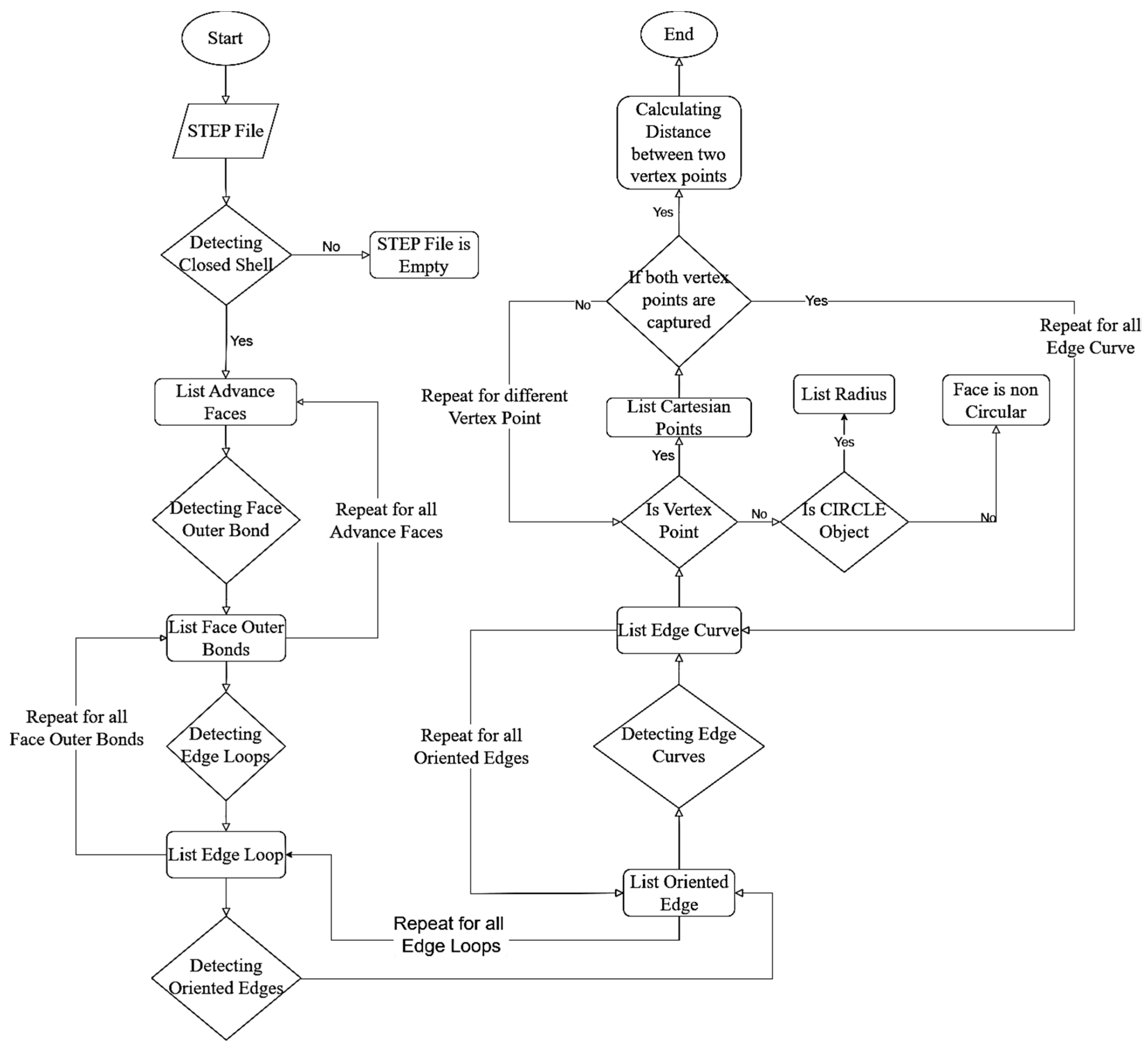
The part’s feature is the generic shape of the part. The extraction of actual dimensions of any part can be carried out using the hierarchical tree structure of STEP files. The STEP file is compiled with two types of the part’s geometric information: face orientation information and face location coordinate points in the CAD workspace environment. To extract the dimensions, these two types of data need to be systematically processed. These extracted dimensions are specifically related to the faces (features) of the parts. These dimensions can be extracted using a specially developed algorithm. The proposed algorithm, as shown in
Figure 2, takes the STEP file as input and outputs the face dimensions, including radiuses of circular sections. Each advance face is processed to obtain the Cartesian points of the borders of the face. This involves the stepwise processing of each STEP file entity of the advanced face. The main STEP file entities, as discussed in the previous section, are FACE_OUTER_BOND, EDGE_LOOP, ORIENTED_EDGE, and EDGE_CURVE. Each face has multiple edges, and these numbers of edges are equal to the number of edge curves in the STEP file for the given face. Each edge curve has three attributes, in which two are vertex points of a given edge, and the third attribute discloses the nature of the edge, which is either circular or linear.
The circular attribute discloses the radial dimension of the edge (radius). Since the linear edge often does not contain any important information within it, the linear dimensions of the edge can be extracted using Cartesian points. Each vertex point contains the Cartesian point of the edge. Hence, all vertex points of the edge are used to calculate the distance between them.
To calculate the distance, the three-dimensional Euclidean distance formula is used [
18], as shown in (1). If
P1 and
P2 are Cartesian points of two adjacent vertex points (
V1,
V2) of edge curve (
Ec), then
d(
P1,
P2) is the linear distance between vertex points. This linear distance between coordinate points (
) and (
) is given as
Further, the extracted dimensional data from the CAD file are stored into a feature-based logical structure in the XML file. In the XML file syntax, elements are the basic components. These elements contain data bounded by the markup tags. The data stored in these elements are represented by the markup tags, and stored data can be numeric or text [
19]. In XML terminology, the information within each element is called content. Content can, again, have a subelement or data stored in it. If the content of an element or sub-element again contains a subelement, then such data storage can be called nested storage. This nested storage helps store data in a hierarchical structure.
Figure 3 shows a proposed structure describing a part.
The expressions <Assembly_Name:> and </ Assembly_Name:> are the markup tags for main element. Each XML file represents one assembly. Assembly element further has subelements, named <Component_1>, <Component_2>, <Component_3>, and so on. These components are basic components of a given assembly. If the extracted dimensions represent a single component and not an assembly, then the main assembly element contains only one component, named <Component_1>. Each component subelement stores another subelement, named ‘Features’. Here, <Feature_1:> and </Feature_1:> are start and end markup tags, respectively. These are also called markups. Each feature contains a unique and separate tag. The tag number is given based on the unique integer (line number) where the specific feature is represented in the STEP file. Further, feature subelement stores the dimensions of the given feature as subelements of features. The start and end tag for such subelements can be of two types: <Dimensions_Linear Length = _____ /> and <Dimensions_Circular Radius = _____ />. The former subelement represents linear dimensions, whereas the latter represents radial dimensions. Each dimensional subelement stores the data; these data can be numerical or text. In the proposed structure, numeric dimensional values are stored in the subelements. For example: <Dimensions_Linear Length = 20 />.
An XML file is a document in which all of the assembly data are stored. In the proposed database format, each assembly is considered as an object that is identified by the ‘assembly key’. This key encompasses all of the assembly information. Under such assembly, various components can exist. Each component has a unique component key. Further, this component key has various features. Each feature is recognized by a feature key, and the feature key contains specific dimensioning information of the component. The features are automatically recognized by the above algorithm, and based on the feature, the XML file creates a new element for respective features.
4. Results
4.1. Example Implementation
For the demonstration, an example part of the connector is shown in
Figure 4. The part material and other specific information are not considered for the demonstration. The design and dimensions of part features are the important segments for the study.
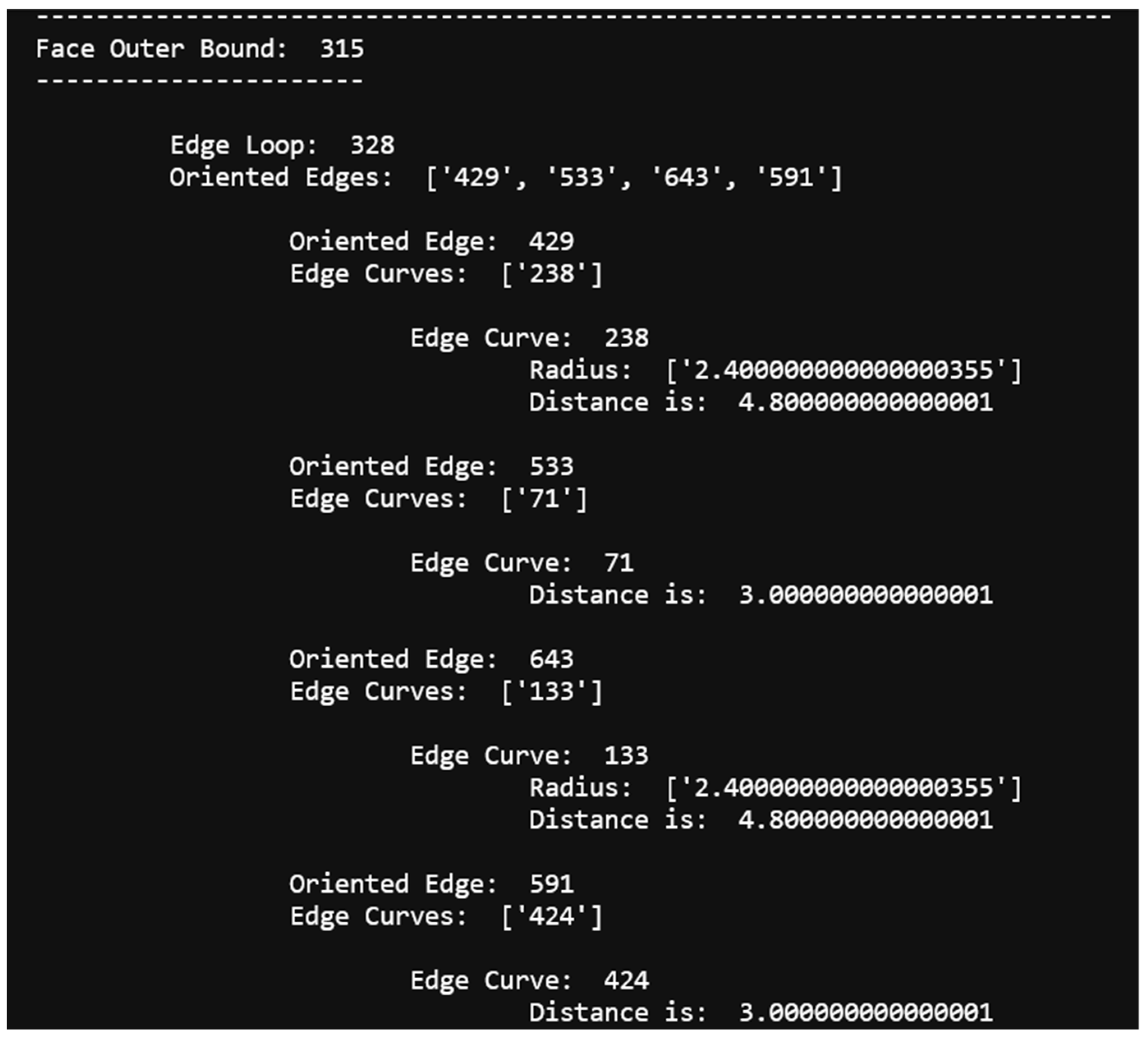
A Python programming language-based application is developed for dimension extraction. Using the algorithm, all dimensions of the part are extracted. A screenshot of the output is shown in
Figure 5. The face shown in output is a semicylindrical internal face of a through-hole with a radius of 2.40 inches and a length of 3.00 inches. The face is highlighted in
Figure 6. The face outer bound 315 in
Figure 5 represents the unique integer of the given face in the STEP file. The proposed algorithm uses the same unique integer to represent the face in the extracted output. This numbering of the face helps in tracking the dimensions down and linking the faces with adjacent faces to define complete features.
The extracted dimensions are further stored in an XML file in feature-based logic. The feature-based logical data structure for storing dimensional data fulfills the application requirements. Since most face edges are shared with adjacent faces, face-level hierarchy helps to reduce the redundancy of dimensional data.
To demonstrate the data structure and the storage schema, data extracted from Step 4 are used to create an XML file.
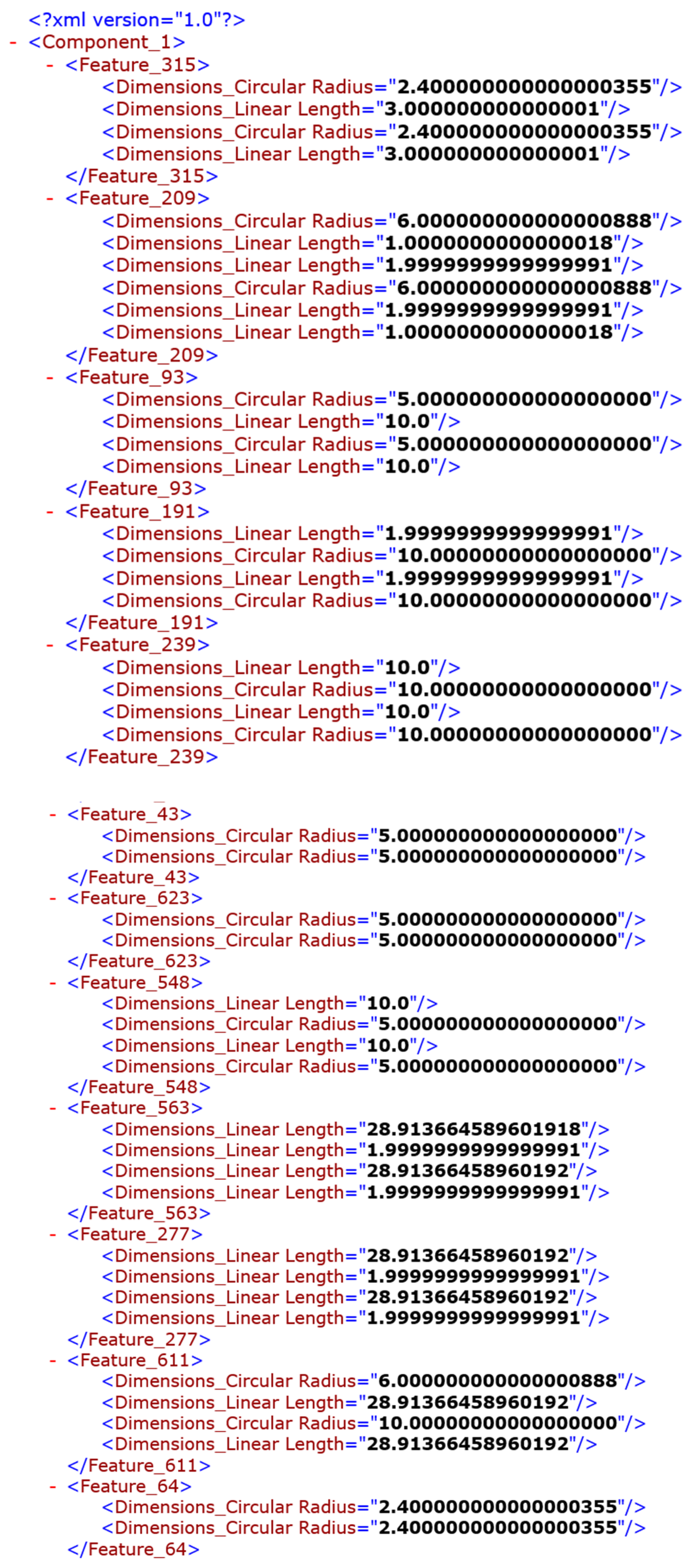
Figure 7 shows the snap of an XML file.
As shown in
Figure 4, the connector part is a single component and not an assembly. Hence, the XML file only has component_1. Within component_1, various features are given. Each feature is represented by the faces that the feature is made of. For instance, the internal face shown in
Figure 6 is represented in Feature_315. The hole (internal face) has a radius of 2.4 inches and a depth of 3 inches. Every feature is represented using a similar representation form. This XML file is generated using an extension for the algorithm. In this connector example, the Python language is used to generate the XML file after extracting the feature-based dimensions from the STEP file.
4.2. Discussion on Application
Demands for parts are usually generated based on shortages accepted by managers, such that subcontracts can be awarded for their manufacture. Contracts are based on making designs available and establishing supply chain networks for timely, economic delivery. In manufacturing democratization, even small manufacturers can set demands for order delivery by other small manufacturers. It is often a process of search and discovery [
20]. Technical details can be provided using a resource, as suggested in this paper, whereby product-to-process mapping can assist in the procurement of specific manufacturing services. Thus, this paper provides the interface between demand and supply for manufacturing democratization.
Part features are important elements of manufacturing parts. Often, the geometric shape, dimensions, and orientation of such part features play a significant role in defining the manufacturing processes and in planning the processing sequence. Design specifications and product manufacturing information of part features are usually implicitly and explicitly embedded in product models and design drawings, and these are important to extract while selecting processes and machines [
21]. In automated process planning systems, different algorithms are often used to understand the part feature information [
22,
23]. This paper provides the interface between design features and product manufacturing through simple XML files. Machine learning and AI can thus be utilized to detect product similarities and process sequencing.
As shown in
Figure 8, let us consider a part with three different types of manufacturing features: an external cylindrical feature, a rectangular feature, and a hole feature. Each of these three features requires a different set of manufacturing processes. These can be extracted using the procedure outlined above.
Figure 9 shows a schematic representation of CAD data sharing between manufacturers. In this transaction, the part features are essential. The part manufacturing features determine the processes and the machine capabilities required for manufacturing the given part. Currently, such manufacturing features are analyzed using human logic. The framework given in this paper helps to store the CAD data in a new and simple schema where such manufacturing features can be accessed directly. Further, using advanced feature recognition algorithms, the features can be labeled. As an extension for this task, in the later stages, the selection of the manufacturing process can be automated using the recognized features.
5. Conclusions
The proposed model provides a framework for the data extraction and storage of part design and manufacturing capability data. The model helps in designing, creating, and populating a database for data generated within manufacturing industries. Moreover, the proposed model can be treated as a framework for understanding the dimensionality of the data for use in predictive analytics. Currently, the part data are stored in 2D and 3D CAD models. The algorithm expands the storage methods into numerical and machine-learnable formats. Part designs mainly explore the geometrical relevance of the feature. Considering this, the XML file format uses geometrical-feature logic to store the part dimensions. This helps in preserving the geometrical information of the parts. Moreover, the method also considers assemblies, and provides single-document storage for assemblies, with parting into the components using XML tags. This has major application potential for complex assembly and part retrieval processes. The XML storage of design data can be used to match similar faces between the different parts. This can give rise to an index for understanding geometric symmetry between parts.
The proposed algorithm for dimensional data extraction provides part design information in a structured way. The algorithm extracts face dimensions and their relationship with other faces. This has particularly significant importance for recognizing underlying patterns, and extends the machine learning applicability for performing various tasks. Each part that is stored in 3D format can be stored and used in a dimension-based numeric XML file. The part dimensions can be used to create search engines and further store the designs in a machine-recognizable format. An XML file with feature-based dimensions gives a dimensional representation of the part data based on the features. The proposed algorithm reads and extracts the dimensions with respect to each face of the given part design. Such a strategy preserves the dimensional and face relevance. This uniform structure of design data provides uniform data from machine learning algorithms to be processed, in order to detect hidden patterns and develop pattern-based predictive algorithms.
All these, in turn, are expected to facilitate further research in applying machine learning approaches for design data for detecting patterns, along with developing advanced algorithms for matching manufacturing capabilities to the product design. Furthermore, the next steps in the research can be taken by using the proposed XML structure to expand the extracting and storing product manufacturing information (PMI).
Author Contributions
Conceptualization, B.G.; methodology, B.G.; software, B.G.; validation, B.G. and S.R.; formal analysis, B.G.; investigation, B.G.; resources, B.G.; data curation, B.G.; writing—original draft preparation, B.G.; writing—review and editing, S.R.; visualization, B.G.; supervision, S.R.; project administration, S.R. All authors have read and agreed to the published version of the manuscript.
Funding
This research received no external funding.
Data Availability Statement
Data sharing not applicable.
Conflicts of Interest
The authors declare no conflict of interest.
List of Acronyms
| Abbreviation | Meaning |
| SCAD | Computer-Aided Design |
| 3D | Three-Dimensional |
| XML | Extensible Markup Language |
| 2D | Two-Dimensional |
| STEP | Standard for the Exchange of Product Data |
| ISO | International Organization for Standards |
| PMI | Product Manufacturing Information |
References
- Alemanni, M.; Destefanis, F.; Vezzetti, E. Model-based definition design in the product lifecycle management scenario. Int. J. Adv. Manuf. Technol. 2011, 52, 1–14. [Google Scholar] [CrossRef]
- Fang, F.Z.; Li, Z.; Arokiam, A.; Gorman, T. Closed Loop PMI Driven Dimensional Quality Lifecycle Management Approach for Smart Manufacturing System. Procedia CIRP 2016, 56, 614–619. [Google Scholar] [CrossRef]
- Stjepandić, J.; Wognum, N.; Verhagen, W.J.C. Concurrent Engineering in the 21st Century; Springer: Berlin/Heidelberg, Germany, 2015. [Google Scholar]
- Sreeramulu, D.; Rao, C. A New Methodology for Recognition of Milling Features from STEP File. Int. J. Appl. 2008, 6, 172–190. Available online: http://www.publishing.waldenu.edu/ijamt/vol6/iss3/9/ (accessed on 26 June 2021).
- Al-Wswasi, M.; Ivanov, A. A novel and smart interactive feature recognition system for rotational parts using a STEP file. Int. J. Adv. Manuf. Technol. 2019, 104, 261–284. [Google Scholar] [CrossRef]
- Oussama, J.; Abdelilah, E.; Ahmed, R. Manufacturing Computer Aided Process Planning for Rotational Parts. Part 1: Automatic Feature Recognition from STEP AP203 Ed2. J. Eng. Res. Appl. 2014, 4, 2248–9622. Available online: www.ijera.com (accessed on 7 August 2021).
- Ismail, N.; Tan, C.F.; Wong, S.V.; Osman, M.R.; Sulaiman, S. Ruled-Based Feature Extraction and Recognition. In Proceedings of the Student Conference on Research and Development, Shah Alam, Malaysia, 17 July 2002; pp. 3–6. [Google Scholar]
- Ketan, H.S.; Haleel, A.J. STEP-Based Assembly Feature Recognition Using Attribute Adjacency Graph for Prismatic Parts. Eng. Technol. J. 2013, 31, 1929–1948. [Google Scholar]
- Venu, B.; Komma, V.R.; Srivastava, D. STEP-based Feature Recognition System for B-spline Surface Features. Int. J. Autom. Comput. 2018, 15, 500–512. [Google Scholar] [CrossRef]
- Wang, J. Research on Shape Feature Recognition of B-Rep Model Based on Wavelet Transform. Math. Probl. Eng. 2018, 2018, 1–8. [Google Scholar] [CrossRef]
- Kalpakjian, S.; Steven, S. Manufacturing Engineering and Technology, 7th ed.; Kalpakjian, S., Schmid, S.R., Eds.; Pearson Education, Inc.: London, UK, 2014. [Google Scholar]
- Eftekharian, A.A.; Campbell, M.I. Convex Decomposition of 3D Solid Models for Automated Manufacturing Process Planning Applications. Proc. ASME Des. Eng. Tech. Conf. 2012, 2, 727–735. [Google Scholar] [CrossRef]
- Qi, C.R.; Yi, L.; Su, H.; Guibas, L.J. PointNet++: Deep hierarchical feature learning on point sets in a metric space. Adv. Neural Inf. Process. Syst. 2017, 30, 5100–5109. [Google Scholar]
- Charles, R.Q.; Su, H.; Kaichun, M.; Guibas, L.J. PointNet: Deep Learning on Point Sets for 3D Classification and Segmentation. In Proceedings of the 2017 IEEE Conference on Computer Vision and Pattern Recognition (CVPR), Honolulu, HI, USA, 21–26 July 2017; pp. 77–85. [Google Scholar] [CrossRef]
- Zhang, Z.; Jaiswal, P.; Rai, R. FeatureNet: Machining feature recognition based on 3D Convolution Neural Network. Comput. Des. 2018, 101, 12–22. [Google Scholar] [CrossRef]
- Koch, S.; Matveev, A.; Jiang, Z.; Williams, F.; Artemov, A.; Burnaev, E.; Alexa, M.; Zorin, D.; Panozzo, D. ABC: A Big CAD Model Dataset for Geometric Deep Learning. In Proceedings of the Computer Society Conference on Computer Vision and Pattern Recognition, Long Beach, CA, USA, 15–20 June 2019; pp. 9593–9603. [Google Scholar] [CrossRef]
- Sateesh, P.; Mahesh, P. Subject: Mechanical Engineering IJRIME A Methodology for Feature Extraction and Recognition for CAD/CAM Integration Using Step File tm© all copyrights reserved. Int. J. Res. Innov. Subj. 2017, 4, 711–725. [Google Scholar]
- ScienceDirect. Eucledian Distance. 2020. Available online: https://www.sciencedirect.com/topics/mathematics/euclidean-distance (accessed on 30 June 2020).
- Abiteboul, S.; Buneman, P.; Suciu, D. Data on the Web: Semistructured Data and XML, 1st ed.; Morgan Kaufmann: San Fransico, CA, USA, 2000. [Google Scholar]
- Starly, B.; Cohen, P.; Raman, S. Automating the Search and Discovery of Manufacturing Service Providers to Enable a Digital Supply Chain Network. Smart Sustain. Manuf. Syst. 2020, 4, 276–280. [Google Scholar] [CrossRef]
- Favi, C.; Mandolini, M.; Campi, F.; Germani, M. A CAD-based design for manufacturing method for casted components. Procedia CIRP 2021, 100, 235–240. [Google Scholar] [CrossRef]
- Kathe, C. Improving Product Design Tolerances Using Metr-Ontology; University of Oklahoma: Norman, OK, USA, 2018. [Google Scholar]
- Irani, S.A.; Koo, H.-Y.; Raman, S. Feature-based operation sequence generation in CAPP. Int. J. Prod. Res. 1995, 33, 17–39. [Google Scholar] [CrossRef]
| Disclaimer/Publisher’s Note: The statements, opinions and data contained in all publications are solely those of the individual author(s) and contributor(s) and not of MDPI and/or the editor(s). MDPI and/or the editor(s) disclaim responsibility for any injury to people or property resulting from any ideas, methods, instructions or products referred to in the content. |
© 2023 by the authors. Licensee MDPI, Basel, Switzerland. This article is an open access article distributed under the terms and conditions of the Creative Commons Attribution (CC BY) license (https://creativecommons.org/licenses/by/4.0/).


