Article

Characterization of the Fracture Forming Limits by Radial Extrusion †

by
Rui F. V. Sampaio
1,
João P. M. Pragana
1,
Ivo M. F. Bragança
1,2,
Carlos M. A. Silva
1,
Chris V. Nielsen
3 and
Paulo A. F. Martins
1,*
1
IDMEC, Instituto Superior Técnico, Universidade de Lisboa, 1049-001 Lisbon, Portugal
2
CIMOSM, Instituto Superior de Engenharia de Lisboa, Instituto Politécnico de Lisboa, 1959-007 Lisbon, Portugal
3
Department of Civil and Mechanical Engineering, Technical University of Denmark, 2800 Kgs. Lyngby, Denmark
*
Author to whom correspondence should be addressed.
This paper is an extended version of our paper “Rui F.V. Sampaio, João P.M. Pragana, Ivo M.F. Bragança, Carlos M.A. Silva, Chris V. Nielsen, Paulo A.F. Martins. On the Utilization of Radial Extrusion to Characterize Fracture Forming Limits”. In Proceedings of the 20th International Conference on Sheet Metal (SHEMET 2023), Erlangen-Nürnberg, Germany, 2–5 April 2023.
J. Manuf. Mater. Process. 2023, 7(3), 107; https://doi.org/10.3390/jmmp7030107
Submission received: 6 May 2023 / Revised: 22 May 2023 / Accepted: 23 May 2023 / Published: 1 June 2023

Abstract

:
This paper introduces a new formability test based on double-action radial extrusion to characterize material formability in the three-dimensional to plane-stress material flow transitions that are found in bulk metal-formed parts. The presentation draws from a multidirectional tool, which was designed to convert the vertical press stroke into horizontal movement of the compression punches towards each other, aspects of experimental strain determination, fractography, and finite element analysis. Results show that three-dimensional to plane-stress material flow transitions at the radially extruded flanges lead to different modes of fracture (by tension and by shear) that may or may not be preceded by necking, such as in sheet metal forming. The new formability test also reveals adequate characteristics to characterize the failure limits of very ductile wrought and additively manufactured metallic materials, which cannot be easily determined by conventional upset compression tests, and to facilitate the identification of the instant of cracking and of the corresponding fracture strains by combination of the force vs. time evolutions with the in-plane strains obtained from digital image correlation.

1. Introduction

The fracture locus in bulk metal forming is commonly determined by means of upset compression tests performed on cylindrical and tapered specimens and is usually plotted in principal strain space ( ε 1 , ε 2 ) as a straight line with slope ‘−1/2′ falling from left to right [1] (Figure 1). This line is the graphical representation of the positive and negative strain values that a material withstands at the onset of cracking by out-of-plane shearing, as recently proved by Martins et al. [2] and earlier proposed by Kobayashi [3] after observing that vertical and inclined cracks found on the outer surface of these specimens do not run radially.
The proposal of a bilinear fracture locus in principal strain space [4] resulting from the combination of the fracture limit line of slope ‘−1/2′ with a second fracture limit line of slope ‘−1′, is essential to match the strains at failure of the cylindrical and tapered specimens with those of the tensile and upset compression tests performed on rod and cylindrical flanged specimens. This second fracture limit line of slope ‘−1′ corresponds to failure by tension [5] and, in the case of cylindrical flanged specimens, the morphology of the cracks is consistent with the experimental observation of vertical cracks running radially at the outer surfaces [6].
Although the bilinear fracture locus is consistent with the experimental results obtained with the different formability test specimens, it gives rise to an ‘uncertainty region’ (Figure 1) within which failure occurs by mixed modes resulting from competition between cracking by tension (mode I) and by out-of-plane shearing (mode III). This was recently confirmed by Sampaio et al. [7], who designed a new test specimen to investigate the morphology of the cracks in the ‘uncertainty region’ of the principal strain space and concluded that fracture was triggered by out-of-plane shearing (mode III) and propagated radially by tension (mode I).
Transitions from crack opening by mode I to propagation by mode III at the leftmost corner of the ‘uncertainty region’ were previously observed by the authors during upset compression of cylindrical flanged test specimens made from aluminum AA2030-T4 [8].
In view of the above, Sampaio et al. [7] proposed a new ductile damage criterion based on a combination of the Cockcroft and Latham [9] criterion corresponding to crack opening by mode III with a modified version of the McClintock [10] criterion commonly used in crack opening by mode I to model ductile damage over the entire range of stress-triaxiality values, including the ‘uncertainty region’ of crack opening by mixed modes.
Although research on formability and crack opening modes has been directly or indirectly associated with stress triaxiality and, sometimes, also with the Lode parameter [11], there are aspects related to material flow transitions that are not commonly taken into consideration. Accountability of these aspects means, in practical terms, including the three-dimensional to plane stress material flow transitions (i.e., bulk-to-sheet evolutions) in the list of parameters that are responsible for the competition between the different crack opening modes.
Figure 2 shows examples of bulk-formed parts where plane stress is likely to occur in regions subjected to extensive plastic material flow (refer to the pink-colored regions of the solid rod flange, connecting rod, and tube flange, where the final thickness is much smaller than that of the preforms). The connecting rod is a good example of a well-known occurrence of three-dimensional to plane-stress transitions when excess material flows into the flash gutter during impression-die forging.
Upcoming trends in hybrid additive manufacturing (HAM) show a growing interest in the combination of wire-arc additive manufacturing (WAAM) with metal forming. WAAM is a type of direct-metal deposition that can use gas metal arc, gas tungsten arc, or plasma arc (Figure 3) as heat sources [12] and share working principles with well-known arc welding processes [13]. The attractiveness of WAAM in both industry and academia comes from the low capital investment and the option to use already available equipment from various well-established suppliers of welding machines [14,15]. However, this hybridization between WAAM and metal forming comes with the need to study the forming limits of additively manufactured metals.
Under these circumstances, the main objective of this paper is to investigate formability in three-dimensional to plane-stress material flow transitions by means of a new formability test based on the working principle of double-action radial extrusion [16] on both wrought and additively manufactured aluminum alloys. The paper is an extension of previous work of the authors in wrought aluminum alloys [17,18] and, as will be shown, depending on the aspect ratio and overall ductility of the specimens, the diameter-to-thickness ratio of the radially extruded flange may reach typical plane stress values. This allows analyzing strain path evolutions and failures in three-dimensional to plane-stress material flow transitions by means of digital image correlation (DIC), scanning electron microscopy (SEM), and finite element modeling.
However, the relevance of the new proposed formability test goes beyond the above-mentioned material flow transitions because it provides two significant advantages over the existing bulk formability tests. Firstly, it allows carrying out tests with very slender cylindrical specimens, which would inevitably collapse by buckling during upset compression tests between flat parallel platens. This overcomes the difficulty of obtaining the experimental strains at fracture in very ductile materials, a topic that was also addressed by Bulzak et al. [19] when studying damage evolution in hot forming with rotary compression tests. However, the experimental evaluation of surface strains becomes very difficult for this test, due to the continuous movement of the specimen.
Secondly, the fact that triggering and subsequent propagation of cracks in the double-action radial extrusion test will always lead to force drops in the force vs. time evolutions. This allows determining the instant of cracking and the corresponding fracture strains by combining the experimental force vs. time evolutions with the results obtained from digital image correlation. In fact, the force vs. time evolution of the double-action radial extrusion test is different from those found in conventional upset compression tests, in which the combination of surface expansion with strain hardening commonly prevents the force from dropping at the onset of cracking.

2. Materials and Methods

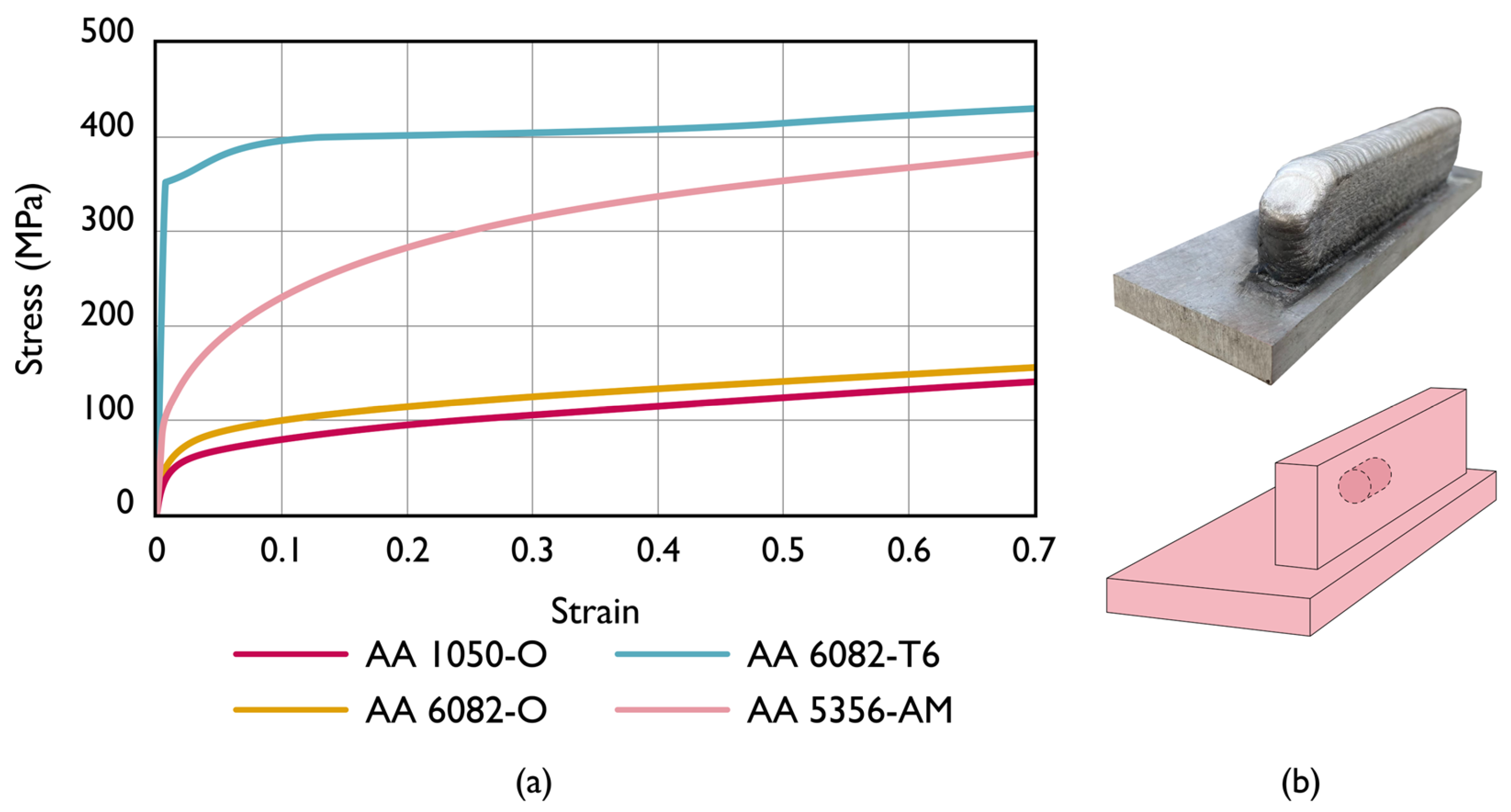
2.1. Material Flow Curves

The investigation was carried out in wrought and additively manufactured materials. The wrought materials consisted of a soft aluminum AA1050-O and a medium-strength aluminum-magnesium-silicon alloy AA6082 in the annealed (O) and solution heat-treated (T6) states. They were supplied in the form of solid rods, and their flow curves were determined by means of compression tests carried out on cylindrical test specimens with a 20 mm diameter and a 20 mm height (Figure 4a).
The additively manufactured material was an AA5356 aluminum alloy deposited with a Fronius TPS 4000 cold metal transfer (CMT) power source coupled to a six-axis Kuka robot. The deposition strategy made use of zigzag (bidirectional) scanning, and the main parameters consisted of an electric current of 94 A, a wire feed speed of 8 m/min, a travel speed of 0.8 m/min, and argon as shielding gas. The cylindrical test specimens with a 10 mm diameter and 10 mm height were machined out of the deposited material in a CNC lathe along the longitudinal direction, as schematically shown in Figure 4b. This material will be hereafter referred to as ‘AA5356-AM’, and its flow curve is also included in Figure 4a.
Similar tests performed with specimens machined out of the deposited material along the vertical and transversal directions provide flow curves with a minor deviation of 7% in the stress response for strain values of 0.7. This result, in conjunction with the preservation of the axial symmetry of the specimens after compression, justifies the reason why anisotropic effects will not be taken into consideration in the numerical modeling.
The compression tests were performed at ambient temperature on an Instron SATEC 1200 kN hydraulic testing machine with a constant crosshead velocity of 5 mm/min. The specimens were lubricated with molybdenum disulfide (MoS2) to ensure near-frictionless conditions.

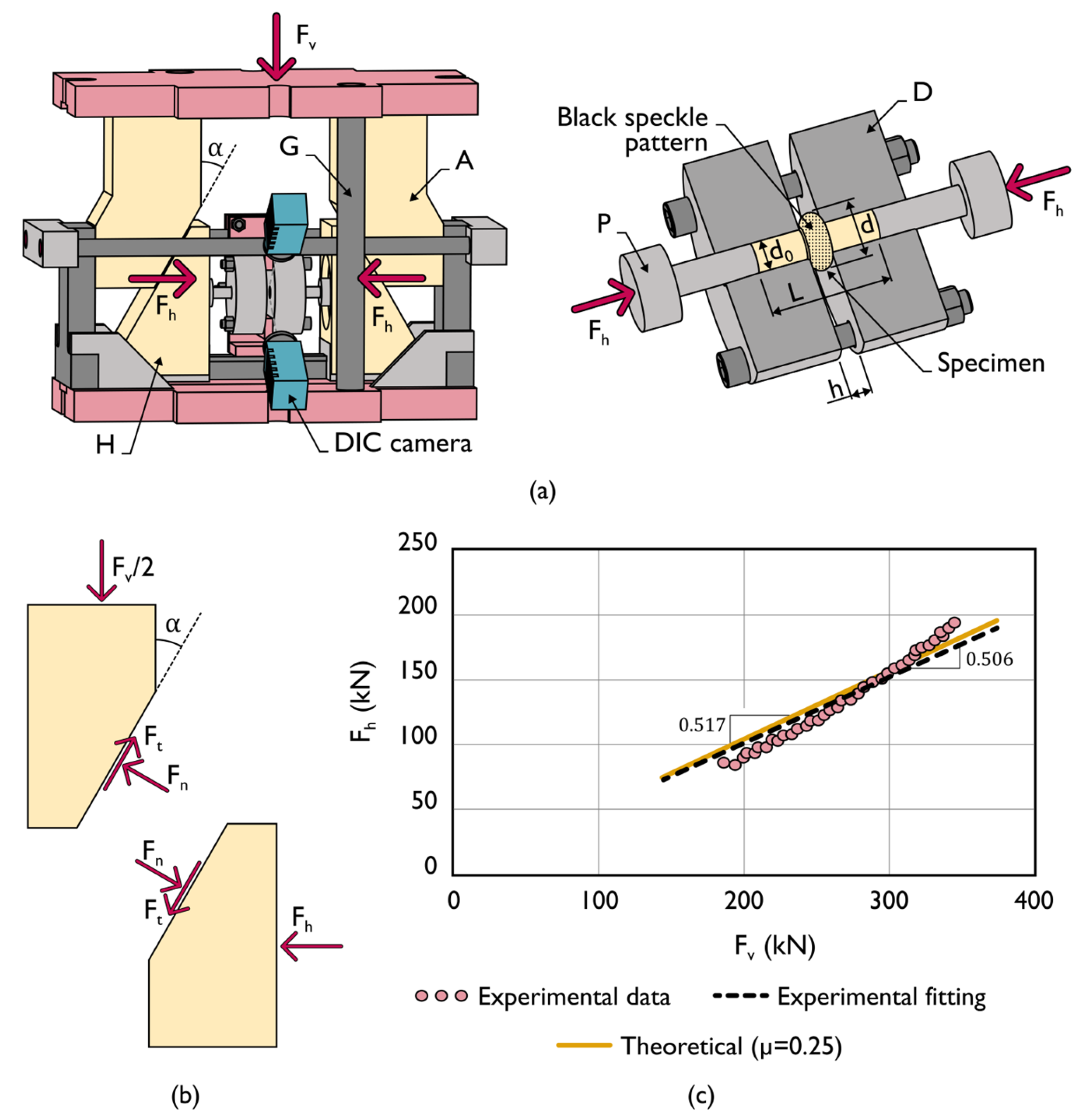
2.2. Double-Action Radial Extrusion Formability Test

The double-action radial extrusion formability tests were carried out with a multidirectional tool set that was designed and constructed by the authors. The tool set allows extruding specimens with different aspect ratios h / d 0 of the free gap height h to the initial diameter d 0 into the volume left between the two dies by compressing the material from two horizontally opposite sides in a single vertical press stroke.
Figure 5a shows a detail of the tool set in which the movement of the extrusion punches (P) towards each other inside the dies (D) is obtained by means of two cam slide units consisting of a punch holder (H) and a die wedge actuator (A) with a working angle α = 30 ° . Two guided pillars (G) ensure the alignment between the upper and lower tool halves.
Force equilibrium along the vertical ( v ) and horizontal ( h ) directions of the cam slide units (refer to the free body diagram in Figure 5b) provides the following relations,
Vertical   direction :   1 2 F v = F n ( sin α + μ cos α ) Horizontal   direction :   F h = F n cos α μ sin α
where F t = μ F n is the friction force, μ is the friction coefficient along the contact surfaces of the cam slide units, and F n is the normal force on these surfaces. The combination of the two parts of the above Equation (1) allows writing the horizontal force ( F h ) as a function of the vertical ( F v ) tool force as follows:
F h = F v cos α μ sin α 2 ( sin α + μ cos α ) = 0.866   F v ,    μ = 0 0.517   F v , μ = 0.25
The tool set was installed on the hydraulic testing machine that had been previously used to determine the material flow curves, and compression of cylindrical test specimens between straight parallel platens with the double-acting cam slide units and using a single-acting system in which the platens were fixed to the upper and lower bolsters of the tool set allowed comparing Equation (2) against experimental data (refer to the pink solid markers in Figure 5c).
The theoretical relation in Figure 5c was calculated for μ = 0.25 and the differences against experimental values at the upper right end are attributed to tool stiffness, elastic deformation, and friction variation along the surfaces of cam slide units. For this reason, a linear trend line (refer to the black dashed line in Figure 5c) with a slope of 0.506 was fitted to the experimental data. This linear fitting is consistent with the theoretical estimate resulting from the free body equilibrium (2) to convert the vertical force F v measured by the load cell into the horizontal applied force F h .
Table 1 provides a summary of the testing conditions that were utilized in the double-action radial extrusion testing. The difference in the dimensions of the wrought and AM test specimens was due to size limitations resulting from the thickness of the deposited material, while the size of the test specimens made from the wrought material was kept larger for a more precise determination of strains by the DIC. All tests were carried out with the extrusion dies lubricated with a molybdenum disulfide-based lubricant.

2.3. Methods and Procedures in Formability Analysis and Fractography

The evolution of the in-plane strains with time ( ε 1 , ε 2 ) = f ( t ) on the outer surface of the radially extruded flanges was obtained with a commercial digital image correlation (DIC) system, model Q-400 3D, from Dantec Dynamics. For this purpose, the initial free gap height h of the specimens located in between the two dies was painted white and subsequently sprayed with a black speckle pattern (Figure 5a and Figure 6c).
The double-action working principle of the proposed radial extrusion formability test facilitates image acquisition because the measuring window of the DIC system (equipped with two six-megapixel resolution cameras with 50.2 focal lenses and an f/8 aperture) is fixed and always centered with the vertical symmetry line of the tool set during the entire duration of the test. An acquisition frequency of 10 Hz, corresponding to 10 images per second, was used. The double-action working principle also allows obtaining symmetric test specimens with a flange diameter d after forming.
The transformation of the major and minor in-plane strain evolutions with time ( ε 1 , ε 2 ) = f ( t ) obtained from DIC into the strain loading paths ε 1 = f ( ε 2 ) of principal strain space was carried out by combining and removing the time dependency from the individual evolutions of the major ε 1 and minor ε 2 in-plane strains. The procedure is schematically illustrated in Figure 6a.
The instant of time t f at which cracks were triggered was obtained through identification of the sudden force drop in the experimental evolution of the radial extrusion force with time (Figure 6b), as earlier proposed by Magrinho et al. [6]. Once t f is determined, the strains at fracture ( ε 1 f , ε 2 f ) are easily retrieved from the individual in-plane strain evolutions with time obtained from DIC (Figure 6a).
After testing, the fractured surfaces were cut out of the specimens for subsequent observation and analysis in a scanning electron microscope (SEM) S2400 from Hitachi. Results are presented in the last section of the paper and provide a correlation between the morphology of the cracks, their opening mechanisms, and the corresponding strain loading paths obtained from DIC.

3. Numerical Simulation

The finite element computer program i-form was utilized to carry out the numerical simulation of the double-action radial extrusion formability test under the different operating conditions given in Table 1. The computer program is built upon the finite element flow formulation [20], and the numerical simulation strategy utilized by the authors took advantage of the facility that i-form offers to exchange data between two- and three-dimensional models. This was possible because experimental observations revealed that specimens undergo rotationally symmetric plastic deformation conditions up to approximately 30% of the total stroke. Only subsequently, with the occurrence of diffuse necking at the outer flange surface, there is evidence of asymmetric plastic deformation.
Figure 7 illustrates the overall numerical simulation strategy for a test specimen made from the wrought AA1050-O aluminum alloy, with the different stages carried out by the computer program being illustrated by means of three distinct images:
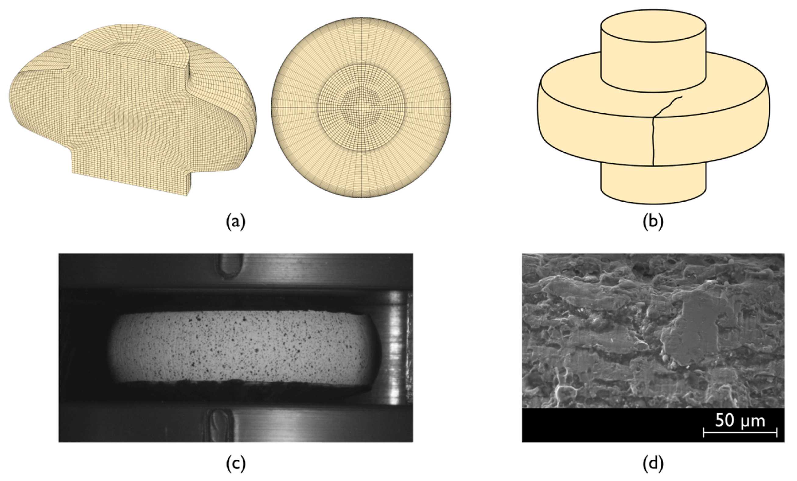
  • Figure 7a refers to the initial two-dimensional simulation under rotationally symmetric conditions in which the test specimen is modeled as a deformable object and discretized by means of quadrilateral elements. The dies and punches are modeled as rigid objects and discretized by means of linear contact elements with friction.
  • Once rotationally symmetric conditions can no longer be utilized, the quadrilateral mesh of the test specimen is automatically rotated counterclockwise about the z-axis to produce a temporary hexahedral mesh similar to that shown in Figure 7b. Scalar field variables are rotated accordingly, but second-order tensors, such as, for example, the strain tensor ε i j , must be properly transformed as follows:
    ε i j x y z = R T ε i j r θ z R
In the above equation, the superscripts x y z and r θ z refer to the cartesian and rotationally symmetric coordinate frames, respectively. The symbol R is the rotation matrix and θ is the angle of rotation shown in Figure 7,
R = cos θ sin θ 0 sin θ cos θ 0 0 0 1
3.
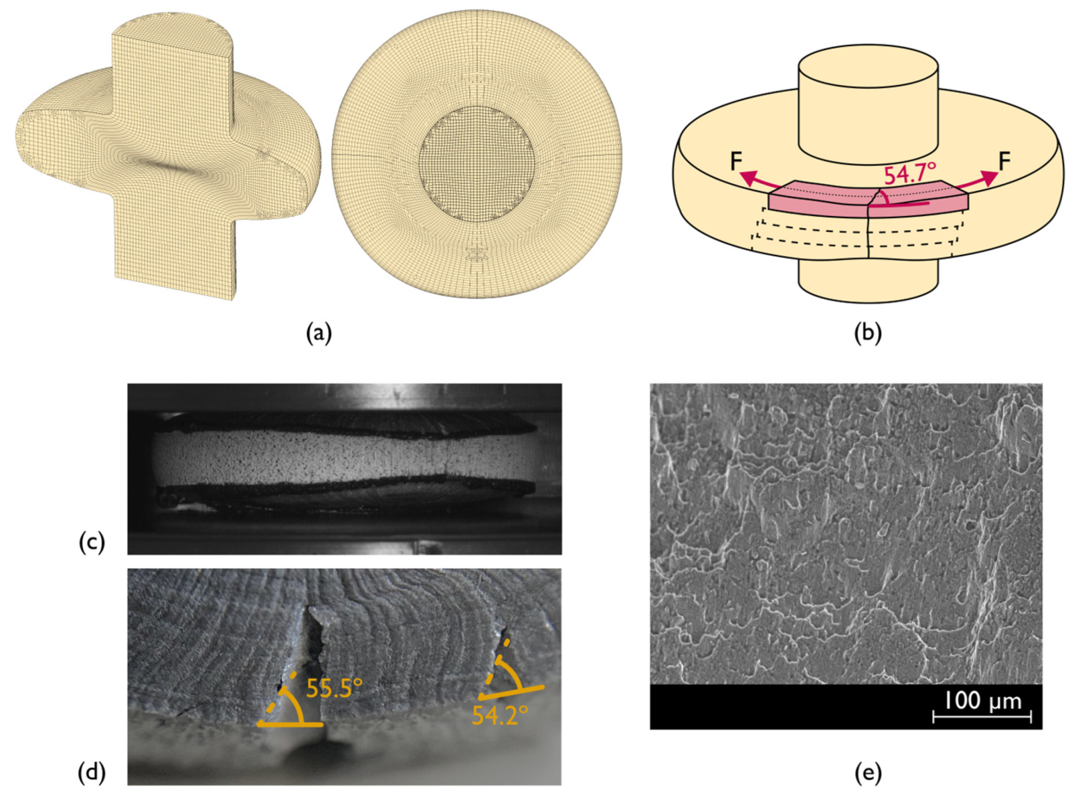
The temporary hexahedral mesh contains a significant number of wedge-shaped elements [21] along the z-axis. These irregular elements are automatically eliminated and replaced by regular hexahedral elements, with field variables properly transferred between the two meshes (Figure 7c). The resulting mesh is symmetric along the zx-plane because the material was assumed to be isotropic. The dies and punches resulting from the rotation of the axisymmetric finite element model continued to be assumed as rigid objects, but their contours were discretized by a mesh of spatial triangles with friction.
The main advantage of the interaction between two- and three-dimensional finite element models is the CPU time savings during the first part of the numerical simulation, in which specimens undergo rotationally symmetric plastic deformation. In fact, the CPU time between the two- and three-dimensional models differs by an order of magnitude of approximately 40 times.

4. Results and Discussion

4.1. Strain Loading Paths in Principal Strain Space

Figure 8 shows the experimental evolutions of the major and minor in-plane strains with time determined by DIC and of the radial extrusion force with time after conversion of the vertical force measured by the load cell (refer to Section 2.2) for the wrought aluminum alloys.
The in-plane strain evolutions were taken from the outer flange surface for the three different materials that were included in the testing conditions of Table 1. As seen, the instant of fracture t f (refer to point ‘F’ in Figure 8a–c) is clearly recognized by a sudden drop in force and allows determining the major ε 1 and minor ε 2 in-plane strains at fracture from their evolutions with time ( ε 1 , ε 2 ) = f ( t ) obtained from DIC. Point ‘I’ is the location on the outer flange surfaces where the strain evolutions were obtained. This point is located at the onset of failure by fracture and is representative of plastic deformation along the equatorial line of the radially extruded flanges.
In the case of the specimens made from wrought AA1050 and AA6082 aluminum alloys in the annealed (O) state, the instant of fracture is preceded by a change in the rate of force growth with time leading to the development of a neck on the outer flange surface (refer to point ’N’ in the force peaks of Figure 8a,b).
In contrast, the specimens made from wrought aluminum AA6082-T6 only experience a sudden drop in force because cracking is not preceded by necking, as experimentally observed and will be shown in the last section of the paper.
The results for the specimens made from the AA5356-AM aluminum alloy are disclosed in Figure 9. As seen from the force vs. time evolution, and similarly to the wrought AA6082-T6 aluminum specimens, the peak in force coincides with a sudden drop in force, meaning that fracture is not preceded by necking.
Application of the methodology that was previously described in Section 2.3 for the wrought and AM aluminum specimens allows plotting the corresponding strain loading paths ε 1 = f ( ε 2 ) in principal strain space. The results are shown in Figure 10 and provide two main trends:
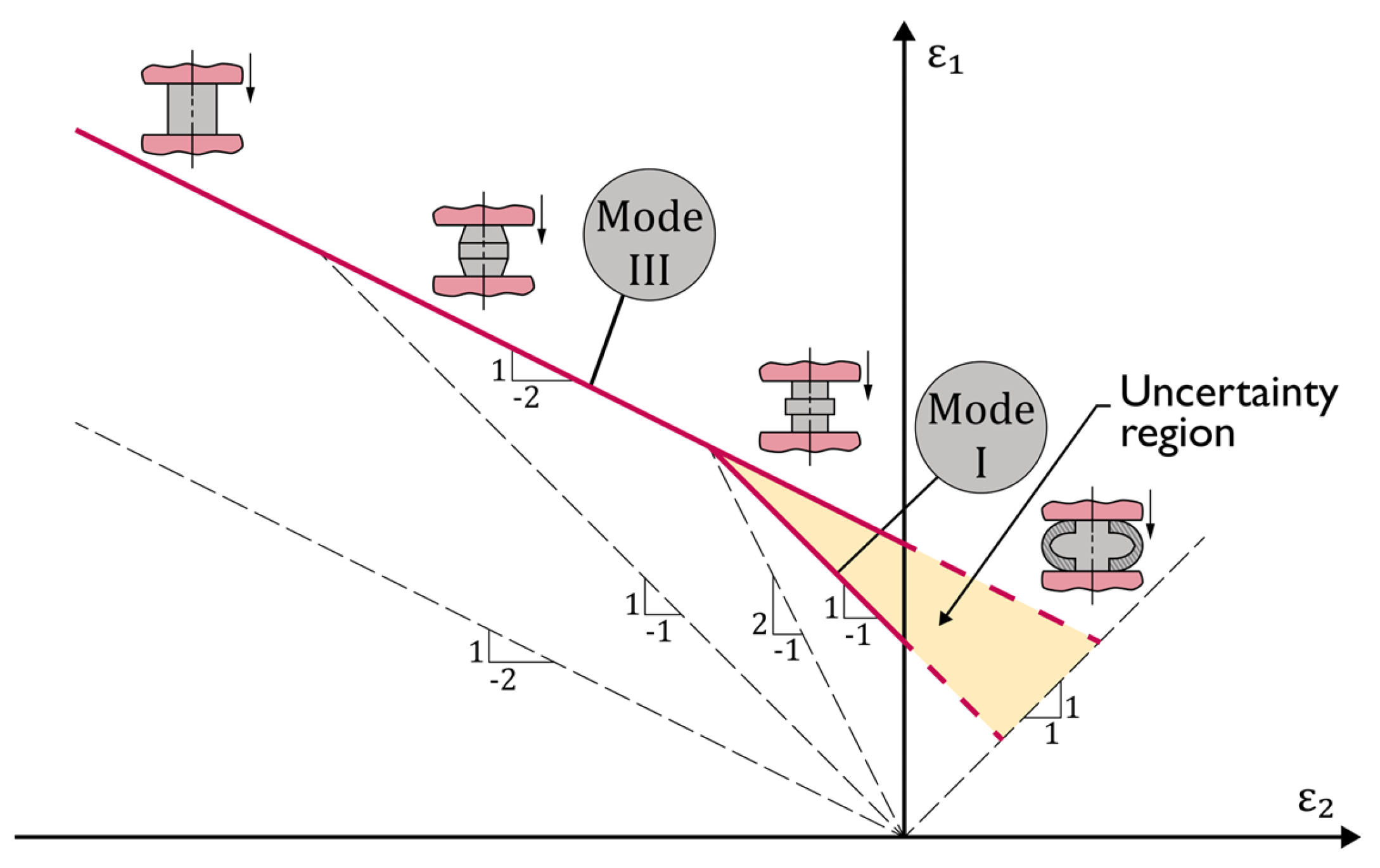
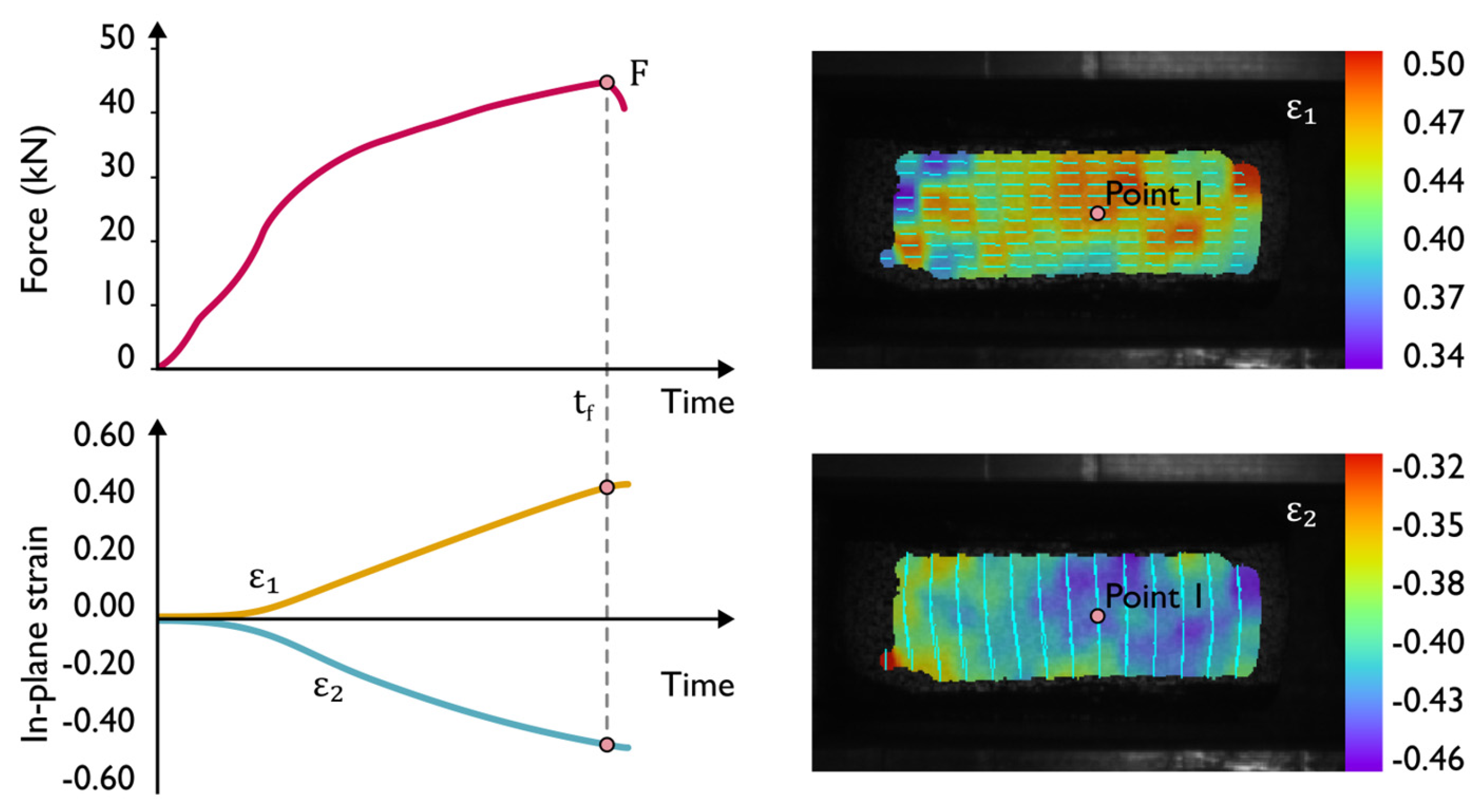
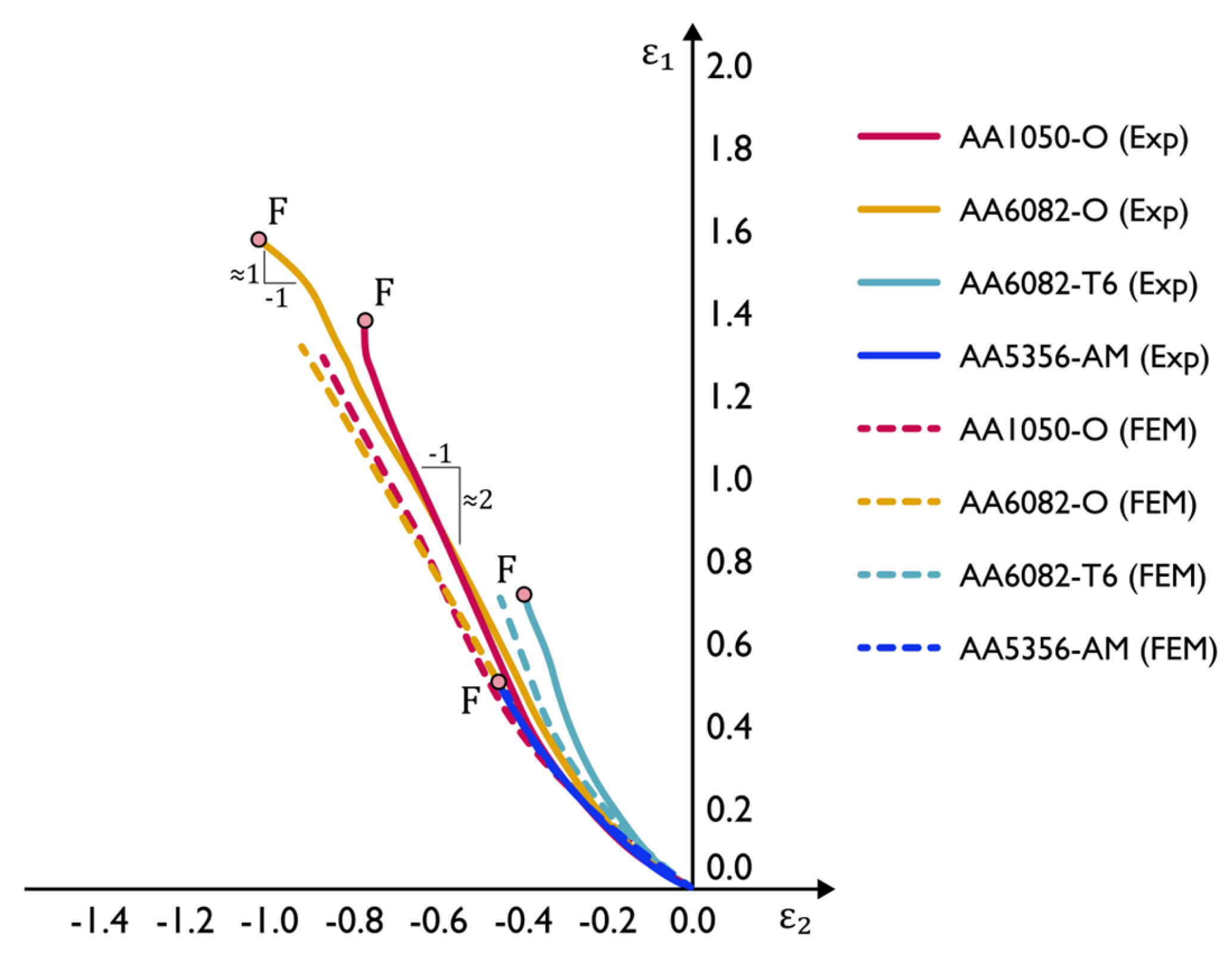
  • Monotonic evolutions up to fracture due to the absence of necking, which mostly maintains a slope close to 1 / 2 , compatible with states of uniaxial tension, such as in the case of the AA6082-T6 and AA5356-AM aluminum specimens,
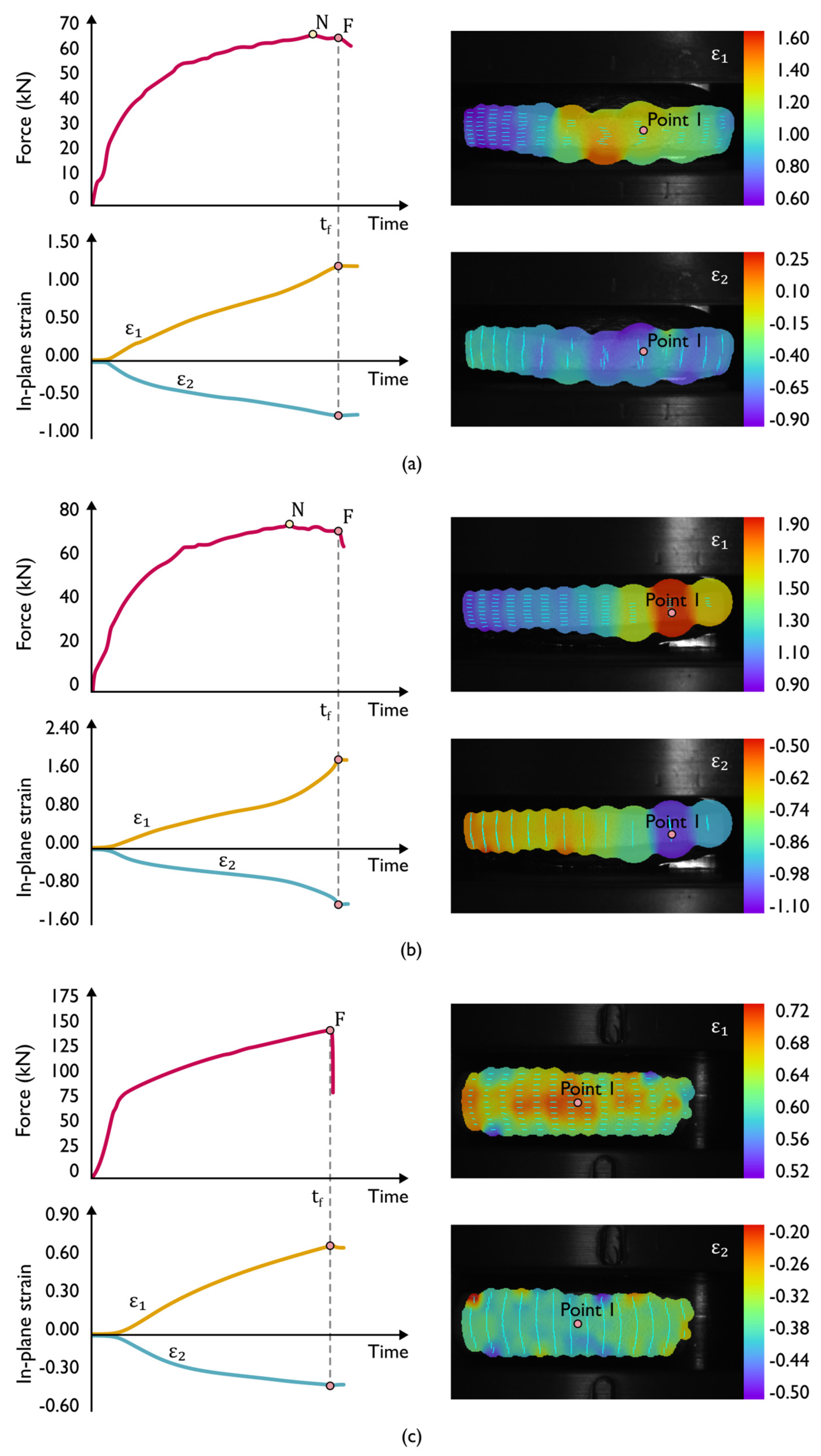
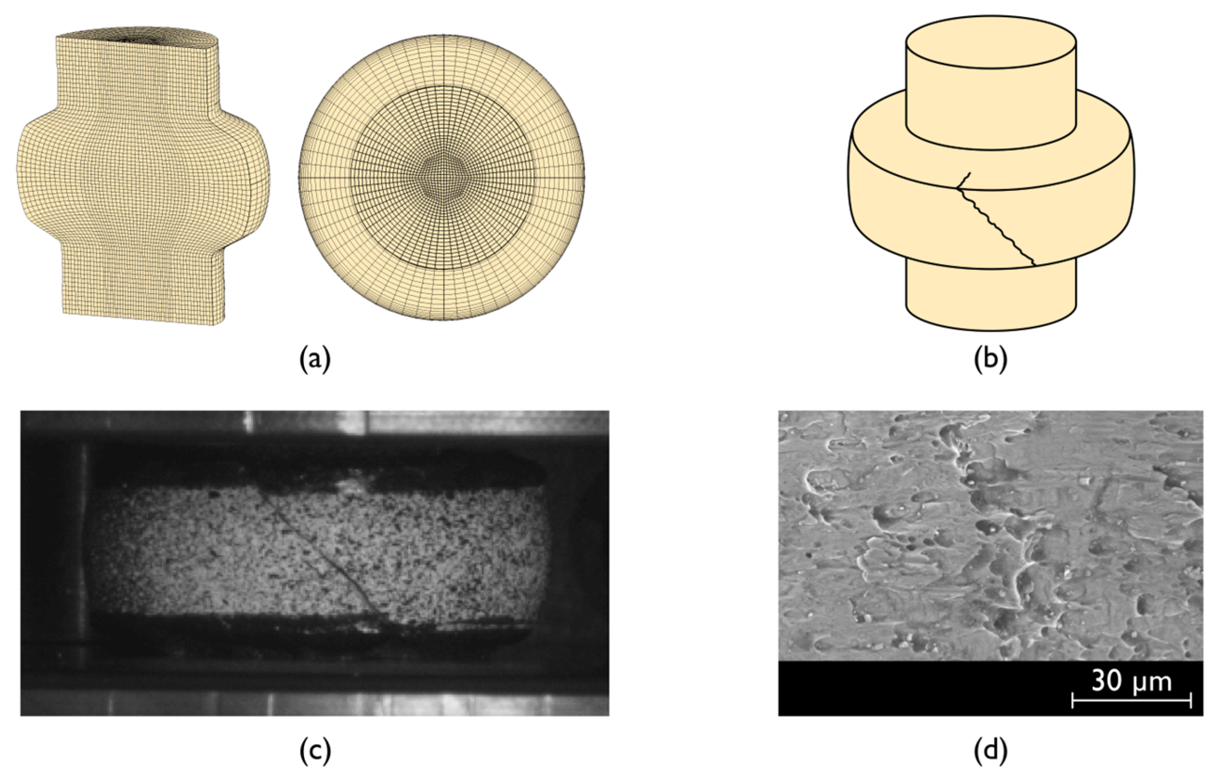
  • Sharp bends of the strain loading paths (immediately before point ‘F’) towards plane strain (AA1050-O aluminum) and pure shear (AA6072-O aluminum) deformation conditions are observed in the specimens where fracture is preceded by necking.
Finite element computed evolutions of the strain loading paths (refer to the dashed lines in Figure 10) show good agreement with the results obtained from DIC. However, the numerical estimates for the soft aluminum AA1050 and the medium strength aluminum-magnesium-silicon alloy AA6082 in the annealed (O) state are only provided up to the onset of localized necking, which corresponds to approximately 80% of the total stroke. Beyond this point, the growth rate of the in-plane strains is very fast, and the uncoupled finite element damage models utilized by the authors experience difficulties in handling the non-homogeneous plastic deformation and the elastic unloading caused by damage-induced softening.
However, because the onset of localized necking and point ‘F’ occur almost instantly, finite elements will continue to be used in the following sections of the paper to analyze the deformation mechanics and the different modes of failure that were observed in the double-action radial extrusion formability test.

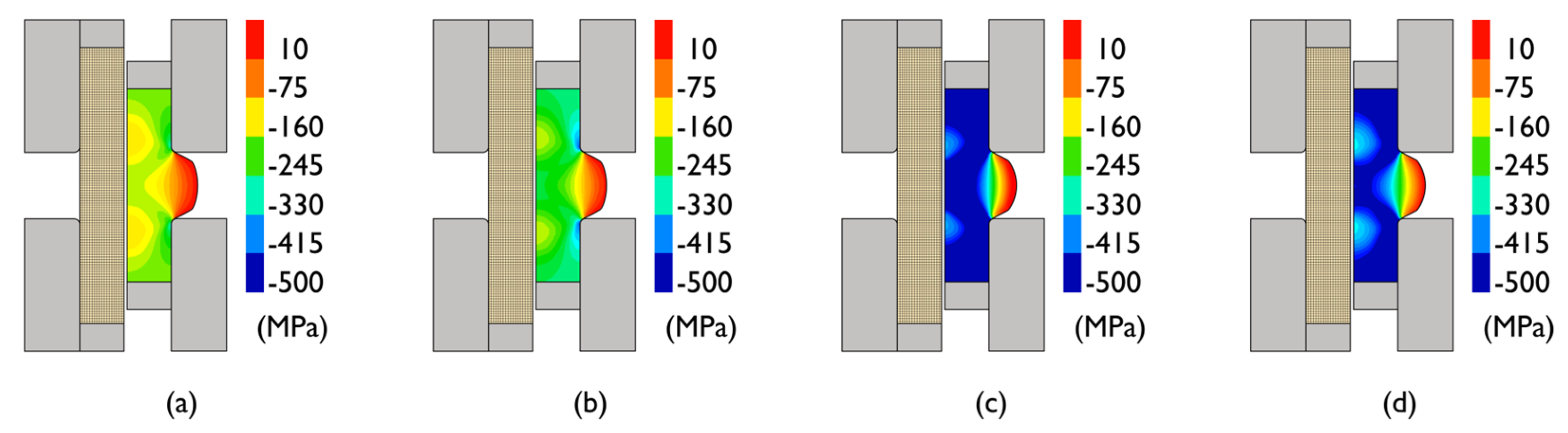
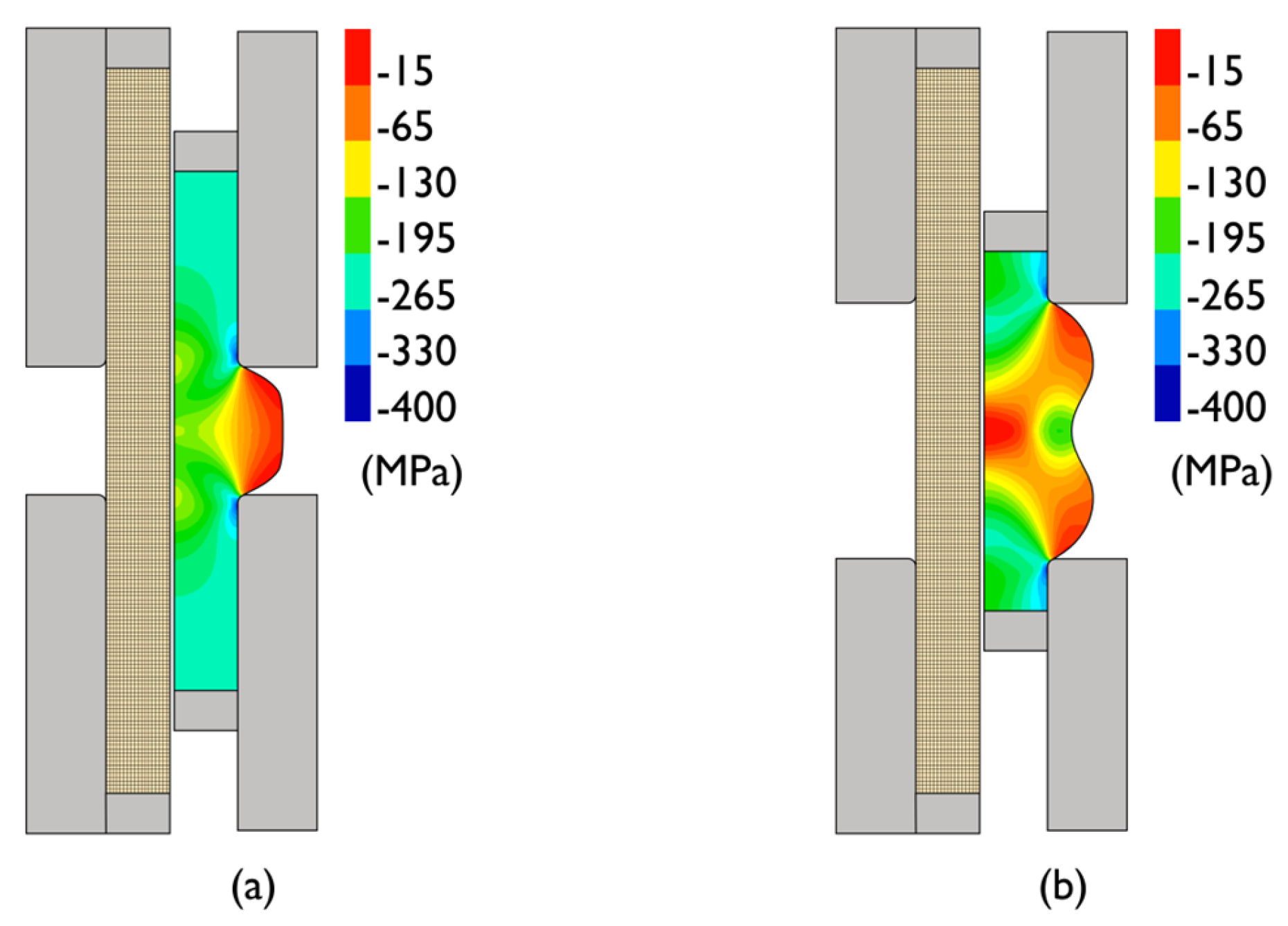
4.2. Deformation Mechanics

Figure 11 shows the initial and intermediate rotationally symmetric meshes at 30% of the total stroke for specimens with an aspect ratio h / d 0 = 0.75 made from the different materials and supplied conditions. As seen in the predicted distribution of vertical stresses, the radially extruded flanges start showing signs of three-dimensional to plane-stress material flow transitions at the outer flange surfaces, which will become more pronounced as radial extrusion continues and the flange diameter increases.
The aspect ratio h / d 0 of the specimens plays a key role in the utilization of radial extrusion as a formability test capable of monitoring the three-dimensional to plane-stress material flow transitions. In fact, larger aspect ratios than those shown in Figure 11 do not give rise to plane stress conditions (Figure 12a) and may result in material flaws (Figure 12b) or buckling, as reported in earlier investigations of the radial extrusion process [22]. In such situations, not only the diameter-to-thickness ratio of the radially extruded flanges deviates from typical sheet forming values, but also the plane stress conditions no longer prevail on the outer flange surfaces.
The asymmetric deformation of the specimens with an aspect ratio h / d 0 = 0.75 that progressively develops during the final stage of the double-action radial extrusion test was simulated with the three-dimensional finite element model built upon the interaction between two- and three-dimensional models that was earlier described in Section 3. For this purpose, the authors artificially imposed small gauge imperfections of approximately 0.2 mm on the outer flange diameter located in the vicinity of the xz-plane. These imperfections account for less than 1% of the flange diameter and correspond to localized material weaknesses that resemble those utilized by Marciniak and Kuczyński [23] in their theory of plastic instability in sheet metal forming.
The result of the above-mentioned strategy combined with intermediate remeshing operations aimed at replacing elements with excessive distortion at the center of the specimens made from AA1050-O and AA6082-O is disclosed in Figure 13. As seen, finite element computed geometries obtained shortly after the onset of cracking agree well with the experimental test specimens (refer to the enclosed photographs).
Incipient crack propagation was numerically modeled by means of an element deletion (removal) technique based on the critical value of a damage function D ,
D = 0 ε g d ε
where g is a weight function [5] and ε is the effective strain.
Two different fracture criteria were used: (i) the McClintock [10], which makes use of stress triaxiality as a weight function g M c = σ m / σ , where σ m is the hydrostatic stress and σ is the effective stress; and (ii) the normalized Cockcroft–Latham [9], which uses the normalized major principal stress σ 1 as a weight function g C L = σ 1 / σ .
The choice between the proper weight function g to be used for each test case was based on the strain loading path evolutions disclosed in Figure 10, which clearly indicate failure by tension preceded by necking in AA1050-O, by out-of-plane shear preceded by necking in AA6082-O, and failure without previous necking in AA6082-T6 and AA5356-AM.
Since failure occurs for stress states of through-thickness plane strain in the case of the AA1050-O specimens, the McClintock criterion, corresponding to failure by tension (mode I), is the best suited for the modeling of the accumulation of damage and fracture initiation (Figure 13a). As for the other specimens, failure occurs for stress states compatible with pure shear (AA6082-O) and uniaxial tension (AA6082-T6 and AA5356-AM), meaning that the normalized Cockcroft–Latham criterion, corresponding to failure by out-of-plane shear (mode III), is the most appropriate (Figure 13b–d). The uppermost scale limits in Figure 13a are the critical values of damage D c r i t for each test case and were obtained by means of inverse analysis after comparing the computed and experimentally measured strains at the onset of cracking.
Further observation of the two different types of necks combined with fractography analysis by means of scanning electron microscopy (SEM) to be presented in the next section provides a better identification and understanding of the different types of failure and modes of deformation that are likely to occur in three-dimensional to plane-stress material flow transitions.

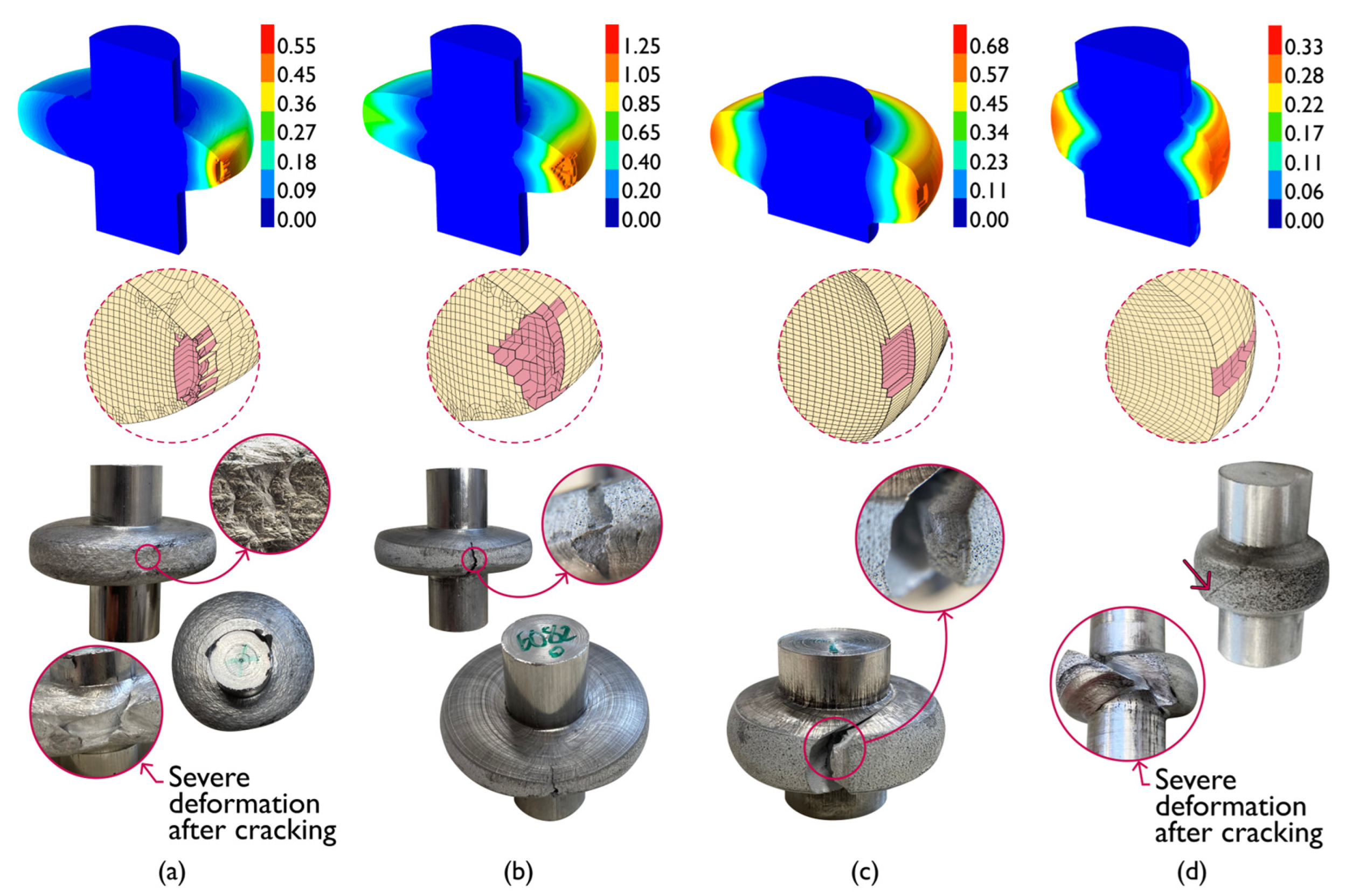
4.3. Necking and Fracture

Combination of the finite element computed meshes with the images obtained from DIC and SEM (Figure 14) allows concluding that fracture in the outer surface flange of the AA1050-O test specimens is by tension (mode I). Results also show evidence of plastic instability in the form of diffuse (Figure 14a) and localized necking (Figure 14c), in good agreement with the deformation mechanics of sheet forming. In fact, the localization of the neck along a direction inclined at an angle of approximately 53.2° (Figure 14c) to the circumferential direction value is very close to the theoretical estimate of 54.7° (Figure 14b) obtained for a sheet (plane stress) specimen made from an isotropic material subjected to uniaxial tension [24].
The morphology of the cracks consists of circular dimple-based structures (Figure 14d), which further corroborates the experimental observation of cracks opening by tension (mode I) and running radially along the flange.
Application of the same methodology for the specimens made from AA6082-O (Figure 15a) confirms that vertical cracks were opened by shear stresses due to the occurrence of smooth parabolic dimple-based structures (Figure 15e). Moreover, these cracks do not run radially along the flange (refer to Figure 13b), as is commonly observed in the upset compression of cylindrical and tapered test specimens, due to significant distortion of the outer flange surface placed within the neighborhood of the localized neck. All this is consistent with the strain path’s bend towards pure shear in principal strain space (refer to Figure 10) before failing by through-thickness shearing (mode III).
The pure shear stress state acting at the outer flange surface (with ε θ = ε z > 0 ) gives rise to plane-strain deformation along the radial direction ( ε r = 0 ) due to material incompressibility. Thus, assuming these conditions hold in between the top and bottom flange surfaces due to the combination of small thickness and plane-stress material flow conditions (refer to Section 4.2), an analogy with the uniaxial tension of a sheet test specimen can also be made.
The analogy requires a similar approach to that taken for the specimen made from AA1050-O, but now with diffuse necking taking place in the radial direction (Figure 15b,c) and crack opening in the r - θ plane after the occurrence of localized necking with angles of approximately 54°~55° (refer to the top flange view in Figure 15d).
Concerning the results obtained for the specimens made from AA6082-T6 (Figure 16a), it is possible to conclude that vertical cracks open without previous necking (Figure 16c). Crack propagation does not run radially, as schematically disclosed in Figure 16b, due to the development of a mixed mode characterized by the simultaneous occurrence of circle and smooth parabolic dimple-based structures (Figure 16d). This can also be observed in the photograph in Figure 13c.
The AA5356-AM specimens (Figure 17a) failed by means of inclined cracks (Figure 17c) running radially (Figure 17b), as is commonly observed in crack opening by out-of-plane shear (mode III). This observation is further corroborated by the occurrence of smooth parabolic dimple-based structures in the SEM images (Figure 17d). However, fractography also shows the existence of some patches of globular dimple structures in the middle of the smoother ones, suggesting some influence of tension (mode I) in the crack opening mechanism. Similarly, to the AA6082-T6, the existence of a mixed mode in the AA5356-AM specimens is in perfect agreement with the concept of uncertainty region that was previously addressed by the authors since fracture occurs under a stress state of uniaxial tension (refer also to Figure 1).

5. Conclusions

The work on the utilization of double-action radial extrusion as a new formability test to characterize failure in bulk sheet material evolutions led to the following main conclusions:
  • The test can be successfully used to characterize the formability of wrought and additively manufactured metallic materials in the three-dimensional to plane-stress material flow transitions that are commonly found in bulk metal-formed parts.
  • Material flow transitions give rise to uniaxial tension states of stress that eventually lead to crack opening with or without previous localized necking.
  • Cracks preceded by localized necking develop under plane strain or pure shear material flow conditions on the outer flange surface.
  • The morphology of the cracks reveals crack opening by tension (mode I), out-of-plane shear (mode III), and a mixed mode resulting from the combination of modes I and III.
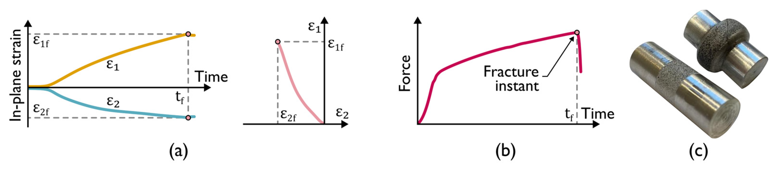
  • Triggering and subsequent propagation of cracks in the new proposed test always leads to force drops in the force vs. time evolutions, thereby allowing an easy identification of the instant of cracking and of the corresponding fracture strains by combination of the force vs. time evolutions with the in-plane strains obtained from digital image correlation.
  • The new test facilitates image acquisition because the measuring window of the DIC system is fixed and always centered on the vertical symmetry line of the tool set during the entire duration of the test.
  • The new test is also adequate to characterize the formability limits of highly ductile materials with large fracture strains, such as aluminum AA1050-O and AA6082-O, which cannot be easily determined by conventional upset compression tests.

Author Contributions

Conceptualization, R.F.V.S., I.M.F.B. and C.M.A.S.; methodology, R.F.V.S., J.P.M.P., I.M.F.B., C.M.A.S., C.V.N. and P.A.F.M.; software, R.F.V.S., C.V.N. and P.A.F.M.; validation, R.F.V.S.; formal analysis, R.F.V.S., J.P.M.P., I.M.F.B., C.M.A.S., C.V.N. and P.A.F.M.; investigation, R.F.V.S., J.P.M.P., I.M.F.B., C.M.A.S., C.V.N. and P.A.F.M.; resources, I.M.F.B., C.M.A.S. and P.A.F.M.; writing—original draft preparation, R.F.V.S. and P.A.F.M.; writing—review and editing, R.F.V.S., J.P.M.P., I.M.F.B., C.M.A.S., C.V.N. and P.A.F.M.; visualization, R.F.V.S.; supervision, I.M.F.B., C.M.A.S. and P.A.F.M.; project administration, P.A.F.M.; funding acquisition, P.A.F.M. All authors have read and agreed to the published version of the manuscript.

Funding

This research was funded by Fundação para a Ciência e a Tecnologia of Portugal and IDMEC under LAETA-UIDB/50022/2020 and PTDC/EME-EME/0949/2020. Rui F.V. Sampaio was funded by Fundação para a Ciência e Tecnologia of Portugal, grant number 2022.12351.BD.

Data Availability Statement

All data supporting the reported results are available in the paper.

Acknowledgments

The authors would like to acknowledge the support provided by Fundação para a Ciência e a Tecnologia of Portugal and IDMEC under LAETA-UIDB/50022/2020 and PTDC/EME-EME/0949/2020. Rui F.V. Sampaio would also like to acknowledge the support under the PhD Studentship 2022.12351.BD.

Conflicts of Interest

The authors declare no conflict of interest.

References

  1. Kuhn, H.A.; Lee, P.W.; Erturk, T.A. Fracture Criterion for Cold Forming. J. Eng. Mater. Technol. 1973, 95, 213–218. [Google Scholar] [CrossRef]
  2. Martins, P.A.F.; Bay, N.; Tekkaya, A.E.; Atkins, A.G. Characterization of Fracture Loci in Metal Forming. Int. J. Mech. Sci. 2014, 83, 112–123. [Google Scholar] [CrossRef]
  3. Kobayashi, S. Deformation Characteristics and Ductile Fracture of 1040 Steel in Simple Upsetting of Solid Cylinders and Rings. J. Eng. Ind. 1970, 92, 391–398. [Google Scholar] [CrossRef]
  4. Erman, E.; Kuhn, H.A.; Fitzsimons, G. Novel Test Specimens for Workability Testing. In Compression Testing of Homogeneous Materials and Composites; Chait, R., Papirno, R., Eds.; ASTM International: West Conshohocken, PA, USA, 1983; pp. 279–290. [Google Scholar] [CrossRef]
  5. Atkins, A.G. Fracture in Forming. J. Mater. Process. Technol. 1996, 56, 609–618. [Google Scholar] [CrossRef]
  6. Magrinho, J.P.; Silva, M.B.; Alves, L.M.; Atkins, A.G.; Martins, P.A.F. New Methodology for the Characterization of Failure by Fracture in Bulk Forming. J. Strain Anal. Eng. Des. 2018, 53, 242–247. [Google Scholar] [CrossRef]
  7. Sampaio, R.F.V.; Pragana, J.P.M.; Bragança, I.M.F.; Silva, C.M.A.; Martins, P.A.F. Revisiting the Fracture Forming Limits of Bulk Forming under Biaxial Tension. Int. J. Damage Mech. 2022, 31, 882–900. [Google Scholar] [CrossRef]
  8. Silva, C.M.A.; Alves, L.M.; Nielsen, C.V.; Atkins, A.G.; Martins, P.A.F. Failure by Fracture in Bulk Metal Forming. J. Mater. Process. Technol. 2015, 215, 287–298. [Google Scholar] [CrossRef]
  9. Cockroft, M.G.; Latham, D.J. Ductility and the Workability of Metals. J. Inst. Met. 1968, 96, 33–39. [Google Scholar]
  10. McClintock, F.A. A Criterion for Ductile Fracture by the Growth of Holes. J. Appl. Mech. 1968, 35, 363–371. [Google Scholar] [CrossRef]
  11. Xue, L.; Wierzbicki, T. Ductile Fracture Initiation and Propagation Modeling Using Damage Plasticity Theory. Eng. Fract. Mech. 2008, 75, 3276–3293. [Google Scholar] [CrossRef]
  12. Shah, A.; Aliyev, R.; Zeidler, H.; Krinke, S. A Review of the Recent Developments and Challenges in Wire Arc Additive Manufacturing (WAAM) Process. J. Manuf. Mater. Process. 2023, 7, 97. [Google Scholar] [CrossRef]
  13. Pragana, J.P.M.; Sampaio, R.F.V.; Bragança, I.M.F.; Silva, C.M.A.; Martins, P.A.F. Hybrid Metal Additive Manufacturing: A State–of–the-Art Review. Adv. Ind. Manuf. Eng. 2021, 2, 100032. [Google Scholar] [CrossRef]
  14. Cunningham, C.R.; Flynn, J.M.; Shokrani, A.; Dhokia, V.; Newman, S.T. Invited Review Article: Strategies and Processes for High Quality Wire Arc Additive Manufacturing. Addit. Manuf. 2018, 22, 672–686. [Google Scholar] [CrossRef]
  15. Dias, M.; Pragana, J.P.M.; Ferreira, B.; Ribeiro, I.; Silva, C.M.A. Economic and Environmental Potential of Wire-Arc Additive Manufacturing. Sustainability 2022, 14, 5197. [Google Scholar] [CrossRef]
  16. Balendra, R. Process Mechanics of Injection Upsetting. Int. J. Mach. Tool Des. Res. 1985, 25, 63–73. [Google Scholar] [CrossRef]
  17. Sampaio, R.F.V.; Pragana, J.P.M.; Bragança, I.M.F.; Silva, C.M.A.; Nielsen, C.V.; Martins, P.A.F. On the Utilization of Radial Extrusion to Characterize Fracture Forming Limits. Part I—Methodology and Tooling. In Proceedings of the SheMet 2023—The 20th International Conference on Sheet Metal, Erlangen-Nürnberg, Germany, 2–5 April 2023; Materials Research Proceedings. Volume 25, pp. 229–236. [Google Scholar] [CrossRef]
  18. Sampaio, R.F.V.; Pragana, J.P.M.; Bragança, I.M.F.; Silva, C.M.A.; Nielsen, C.V.; Martins, P.A.F. On the Utilization of Radial Extrusion to Characterize Fracture Forming Limits. Part II—Testing and Modelling. In Proceedings of the SheMet 2023—The 20th International Conference on Sheet Metal, Erlangen-Nürnberg, Germany, 2–5 April 2023; Materials Research Proceedings. Volume 25, pp. 237–244. [Google Scholar] [CrossRef]
  19. Bulzak, T.; Pater, Z.; Tomczak, J.; Wójcik, Ł. A Rotary Compression Test for Determining the Critical Value of the Cockcroft–Latham Criterion for R260 Steel. Int. J. Damage Mech. 2019, 29, 874–886. [Google Scholar] [CrossRef]
  20. Nielsen, C.V.; Martins, P.A.F. Metal Forming, 1st ed.; Elsevier: New York, NY, USA, 2021. [Google Scholar] [CrossRef]
  21. Martello, G. Discretization Analysis in FEM Models. In Proceedings of the MATEC Web of Conferences—International Scientific Conference Week of Science in SPbPU—Civil Engineering, Saint-Petersburg, Russia, 15 April 2016. [Google Scholar] [CrossRef]
  22. Balendra, R.; Qin, Y. Injection Forging: Engineering and Research. J. Mater. Process. Technol. 2004, 145, 189–206. [Google Scholar] [CrossRef]
  23. Marciniak, Z.; Kuczyński, K. Limit Strains in the Processes of Stretch-Forming Sheet Metal. Int. J. Mech. Sci. 1967, 9, 609–620. [Google Scholar] [CrossRef]
  24. Hill, R. A Theory of the Yielding and Plastic Flow of Anisotropic Metals. Proc. R. Soc. Lond. Ser. A Math. Phys. Sci. 1948, 193, 281–297. [Google Scholar] [CrossRef]
Figure 1. Bulk formability tests and fracture limit lines in principal strain space.
Jmmp 07 00107 g001
Figure 2. Schematic representation of bulk forming parts exhibiting regions (refer to the pink color) where material flow takes place under plane stress conditions (solid rod flange, connecting rod, and tube flange).
Jmmp 07 00107 g002
Figure 3. Working principle of WAAM (using plasma arc) with main terminology.
Jmmp 07 00107 g003
Figure 4. (a) Flow curves for the AA1050-O, AA6082-O, AA6082-T6, and AA5356-AM aluminum alloys; (b) schematic representation of a cylindrical AA5356-AM aluminum test specimen machined out of the deposited material along the longitudinal direction.
Jmmp 07 00107 g004
Figure 5. Double-action radial extrusion formability test. (a) Schematic representation of the tool set with details of the dies and punches, and showing the cameras used by the digital image correlation (DIC) system; (b) Free body diagram of the cam slide units; and (c) theoretical and experimental relation between the vertical F v and horizontal F h forces.
Jmmp 07 00107 g005
Figure 6. (a) In-plane strain vs. time evolutions determined by digital image correlation (left) and the result of their combination to obtain the strain loading path in principal strain space (right). (b) Identification of the instant of time at the onset of fracture from force vs. time evolution. (c) Photographs of a specimen made from the AA5356-AM aluminum alloy before and after testing.
Jmmp 07 00107 g006
Figure 7. (a) Initial and intermediate rotationally symmetric (2D) meshes; (b) Counterclockwise rotation of the intermediate rotationally symmetric mesh (a) into a temporary three-dimensional hexahedral mesh; (c) Automatic repairment of the temporary three-dimensional hexahedral mesh to obtain a hexahedral mesh without wedge-shaped elements along the z-axis.
Jmmp 07 00107 g007
Figure 8. Evolutions of the force and in-plane strains vs. time for specimens with an aspect ratio h / d 0 = 0.75 made from wrought aluminum (a) AA1050-O, (b) AA6082-O, and (c) AA6082-T6. The images were taken from DIC immediately before fracture at the location identified as point ‘I’.
Jmmp 07 00107 g008
Figure 9. Evolutions of the force and in-plane strains vs. time for specimens with an aspect ratio h / d 0 = 0.75 made from AA5356-AM aluminum. The images were taken from DIC immediately before fracture at the location identified as point ‘I’.
Jmmp 07 00107 g009
Figure 10. Experimental and finite element predictions predicted strain loading paths in principal strain space for the specimens made from wrought and additively manufactured aluminum alloys.
Jmmp 07 00107 g010
Figure 11. Initial mesh and intermediate rotationally symmetric finite element prediction of vertical stress for the (a) AA1050-O, (b) AA6082-O, (c) AA6082-T6, and (d) AA5356-AM specimens having an aspect ratio h / d 0 = 0.75 .
Jmmp 07 00107 g011
Figure 12. Initial mesh and intermediate rotationally symmetric finite element prediction of vertical stress for specimens with aspect ratios (a) h / d 0 = 1 and (b) h / d 0 = 2 made from AA1050-O aluminum.
Jmmp 07 00107 g012
Figure 13. Finite element prediction of ductile damage with three-dimensional mesh details showing cracks on the outer flange surfaces for the test specimens with an aspect ratio h / d 0 = 0.75 made from (a) AA1050-O, (b) AA6082-O, (c) AA6082-T6, and (d) AA5336-AM aluminum. Ductile damage was calculated according to (a) McClintock [10] and (bd) Cockcroft–Latham [9] criteria, and photographs of the specimens are enclosed for comparison purposes.
Jmmp 07 00107 g013
Figure 14. Failure mode of the aluminum AA1050-O test specimen with an aspect ratio h / d 0 = 0.75 showing (a) the computed finite element mesh, (b) the analogy with localized necking in uniaxial tension of a sheet test specimen, (c) a DIC image showing localized necking at the outer flange surface, and (d) a SEM picture showing the morphology of the cracks.
Jmmp 07 00107 g014
Figure 15. Failure mode of the aluminum AA6082-O test specimen with an aspect ratio h / d 0 = 0.75 showing (a) the computed finite element mesh, (b) the analogy with pure shear within the neighborhood of the localized neck, (c) a DIC image showing localized necking along the longitudinal direction at the outer flange surface, (d) top view detail of the flange near the neck showing crack opening on the r - θ plane with angles, and (e) a SEM picture showing the morphology of the cracks.
Jmmp 07 00107 g015
Figure 16. Failure mode of the aluminum AA6082-T6 test specimen with an aspect ratio h / d 0 = 0.75 showing (a) the computed finite element mesh, (b) a scheme showing vertical cracks that do not propagate radially, (c) a DIC image showing the absence of necking at the onset of cracking, and (d) a SEM picture showing the morphology of the cracks.
Jmmp 07 00107 g016
Figure 17. Failure mode of the aluminum AA5356-AM test specimen with an aspect ratio h / d 0 = 0.75 showing (a) the computed finite element mesh, (b) a scheme showing inclined cracks that propagate radially, (c) a DIC image showing the absence of necking at the onset of cracking, and (d) a SEM picture showing the morphology of the cracks.
Jmmp 07 00107 g017
Table 1. Testing conditions utilized in double-action radial extrusion testing (nomenclature after Figure 4a).
Dies
Gap height h 7.5 mm, 12 mm, 16 mm, 32 mm
Fillet radius r 0.5 mm
Punches
Diameter10 mm, 16 mm
Velocity5 mm/min
Specimens
AA1050-O, AA6082-O, AA6082-T6Initial diameter d 0 16 mm
Initial length l 0 50 mm, 90 mm
Aspect ratio h / d 0 0.75, 1, 2
AA5356-AMInitial diameter d 0 10 mm
Initial length l 0 25 mm
Aspect ratio h / d 0 0.75, 1, 2
LubricationMolybdenum disulfide (MoS2)
Disclaimer/Publisher’s Note: The statements, opinions and data contained in all publications are solely those of the individual author(s) and contributor(s) and not of MDPI and/or the editor(s). MDPI and/or the editor(s) disclaim responsibility for any injury to people or property resulting from any ideas, methods, instructions or products referred to in the content.

