1. Introduction
With the increasing complexity in design, advanced materials, and manufacturing processes, to achieve ever more demanding requirements in weight reduction, safety, reliability, and performance, dissimilar materials are required to be incorporated into very complex geometrical shapes [
1].
Considering the growing use of even more dissimilar materials, it has become crucial to develop new, dependable, and mass-adoptable joining technologies, Correia et al. [
2] evidenced that, among others, friction stir welding (FSW) was a step ahead of other technologies in this field after reviewing several successful cases of dissimilar materials joining, confirming the industrial relevance of this technology. Friction stir welding is a solid-state welding technology that uses a rotational tool to join two material pieces together along the welding path. The tool is plunged into the joining region between both the metallic and polymeric sheets, generating heat through friction and severe plastic strain that enables the joining process [
3,
4,
5,
6,
7].
From the FSW-related literature, it is possible to distinguish (i) dissimilar metal-to-metal joining, which represents most of the published work, and (ii) dissimilar metal-to-polymer joints, a research niche representing a minority portion of the dissimilar joints’ publications. Kumar et al. [
8] proposed a categorization of dissimilar metal-to-metal joints in three groups, considering a combination of the similarity between the base metals and their melting temperatures, as follows:
Group I—Dissimilar joints resulting from similar metals and melting temperatures;
Group II—Dissimilar joints based on dissimilar base metals with similar melting temperatures;
Group III—Dissimilar joints with dissimilar base metals and melting temperatures.
When the base materials exhibit significant physicochemical differences, such as metals and polymers, these joints fall into what can be considered a new category of dissimilarity—Group IV. In this additional category, the joinability of the base materials is even more challenging, taking into consideration their very low miscibility, weldability, and substantially different melting temperatures [
9]. Until recently, mechanical fastening, such as bolting and riveting, and adhesive bonding have been the joining methods of choice to link dissimilar materials that belong to Group IV [
10]. However, Xu et al. [
11] summarized the shortcomings of using these technologies and how they may constrain the industrial usage of dissimilar materials. These limitations are mainly related to environmental conditions, in the case of adhesive bonding, while mechanical fastening tends to exhibit increased mass to counter the stress concentration effects around fastening holes, increasing the structural design limitations. Despite the limited amount of research in this field, some authors successfully combined metals and polymers using FSW as the joining technology, with the main attributes of the joining processes employed by each author being summarized in
Table 1.
From the abovementioned publications, it is noticeable that most of the authors opted to use an aluminum alloy to join in an overlap configuration with a wide variety of polymers, leading to disparate results. The combination of such dissimilar materials was accomplished by employing considerably distinct processing setups, namely, tilting angles varying between 0 and 4 with rotating and travel speeds ranging between 400 and 2000 rpm, and 2.5 cm/min to 2 m/min, correspondingly. Despite the joints’ performances ranging from 15% to 70% of the ultimate tensile strength (UTS) of the polymeric material, the authors identified chemical bonding and mechanical interlocking as the primary mechanisms that enable the joinability between polymers and metals. The development of these joining mechanisms resulted from the combination of several factors, namely, base material positioning, welding configuration and parameters, tool penetration, and even molecular affinity between the base materials.
Regardless of the aforementioned successful FSW cases of metal-to-polymer hybrid joints, new challenges regarding the lack of processing temperature stability throughout the joining processes were signaled by Patel et al. [
17] and Huang et al. [
20]. The authors evidenced how excessive processing temperature negatively affected the thermo-mechanical properties of the polymers, decreasing the joinability of the base materials either due to degradation of the polymeric chain and functional groups or by causing material overflow out of the joining region. Likewise, too-low processing temperatures might also jeopardize the joining ability due to the generation of defects such as voids and tunnels (generally associated with poor material stirring), hindering the formation of structural features that enable mechanical interlocking, as reported by Moshwan et al. [
21] and Khodabakhshi et al. [
22].
The aim of the present research paper is to evaluate the effects of the pin length and process control on the mechanical performance of hybrid joints that combine an aluminum alloy (AA6082-T6) and an engineering-grade polymer—glass fiber-reinforced (GFR) polyphenylene ether (PPE) blended with polystyrene (PS)—by means of FSW. Throughout the series of experimental procedures, thorough analysis and characterization of the effects of the process controls and tool penetration on resulting dissimilar joints were carried out, describing the influence of these variables on the development of the joining morphologies and mechanical performance.
2. Materials and Methods
An engineering-grade polymer, composed of a blend of polyphenylene ether (PPE) and high impact polystyrene (HIPS) reinforced by 20% by weight of short glass fibers, and an aluminum–magnesium–silicon alloy, AA6082-T6, were combined using FSW as the joining technology. The main thermo-mechanical properties of the materials used during the experimental procedures can be found in
Table 2.
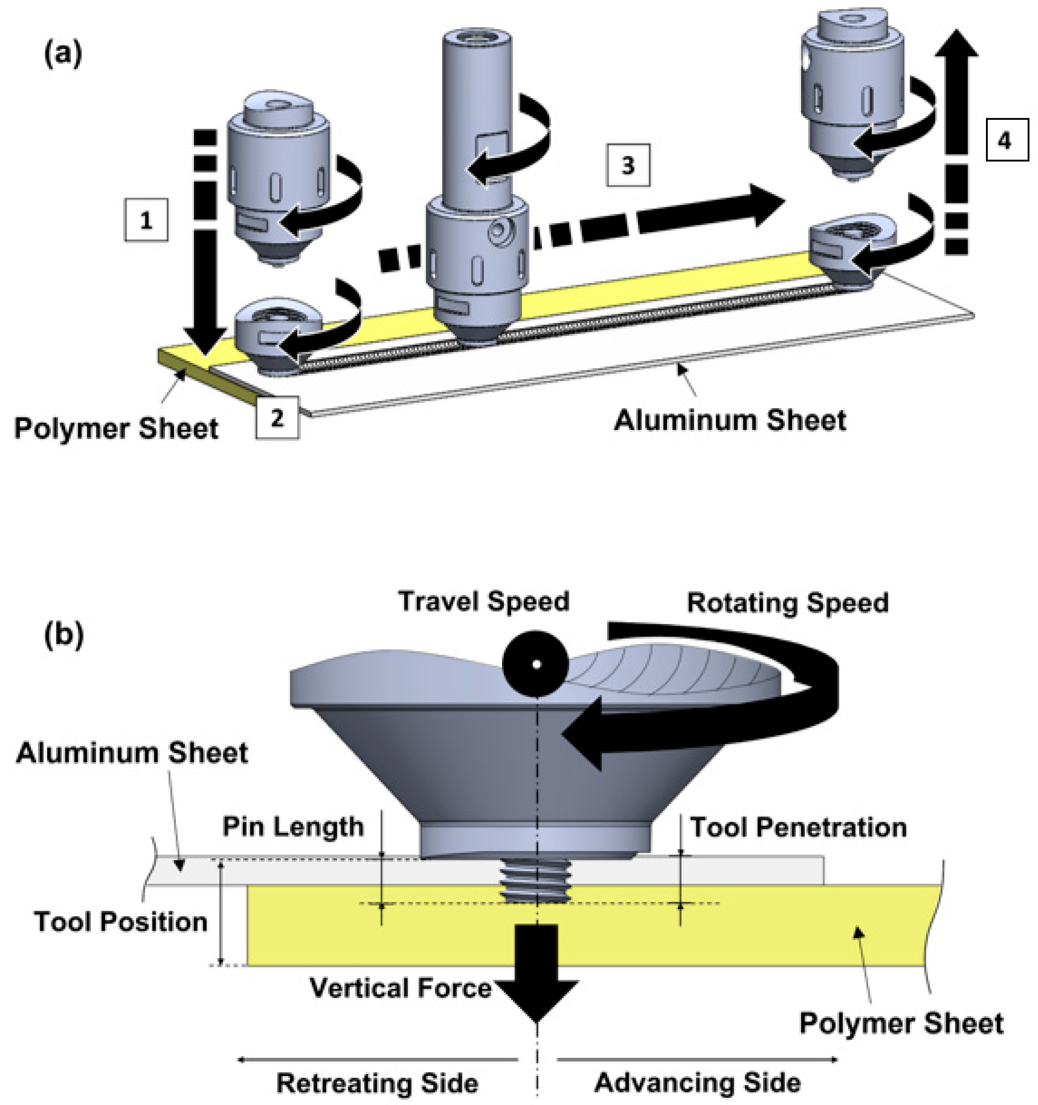
The raw metallic and polymeric sheets, with 2 and 6 mm thicknesses, respectively, were cut into 300 × 125 mm plates and positioned in a lap-joint configuration with 40 mm of superposition. The polymeric plate was placed on the advancing side (AS) of the welding line, underneath the metallic plate, as schematized in
Figure 1.
The experimental procedure was conducted using an ESAB LEGIO 3UL numeric control machine equipped with an FSW modular tool composed of a 5 mm diameter threaded cylindrical probe attached to the shoulder, also threaded, with a 16 mm diameter. Both components of the FSW tool were manufactured using AISI1045, a medium carbon steel, so that proper load transfer and geometrical stability during the joining process were ensured.
As shown in
Figure 1, the overall process can be divided into 4 phases, and the following two parameters were kept constant during all 4 phases: tilt angle of 3
and rotating speed of 600 rpm. The joining process starts with the plunging phase, in which the workpieces are penetrated by the FSW tool at a rate of 0.1 mm/s until it reaches the reference tool position (7.6 mm above the lower surface of the polymeric plate). At this position begins the second phase of the joining process, where the tool rotates in the same position for 15 s dwelling time. During phase 3, the welding phase, the tool travels 250 mm along the welding path at a constant speed of 12 cm/min and, after reaching the end of the path, the tool is extracted (extraction phase) with a vertical speed of 0.1 mm/s, creating an exit hole on the weld seam surface.
In order to assess the effects of the tool penetration and process control on the joints’ morphology and mechanical strength, a parametric study was designed, and the combination of variables used in the fabrication of each joint is listed in
Table 3. After the joints were fabricated, they were machined perpendicularly to the welding path into 25 mm and 5 mm wide specimens. The 25 mm wide specimens were subjected to quasi-static lap shear tensile testing, employed at a rate of 5 mm/min, using an Instron 5566 electro-mechanical testing machine. The 5 mm ones were cold mounted, polished, and etched, being subjected to scanning electron microscopy (SEM) using the analytical SEM Hitachi S2400 equipment.
3. Results and Discussion
3.1. Quasi-Static Tensile Testing
The joining regions exhibit highly non-linear geometries and are subjected to a complex loading configuration that includes tension, secondary bending moment, and shear, leading to a challenging local stress/strain assessment within these regions. Hence, the ultimate tensile strength of the joints (
joint strength) was determined as the average of the remote stress attained by three specimens. The remote stress was calculated in accordance with Equation (1) in which the ultimate tensile load (
UTL) of each joint was divided by the polymer’s cross-sectional nominal area:
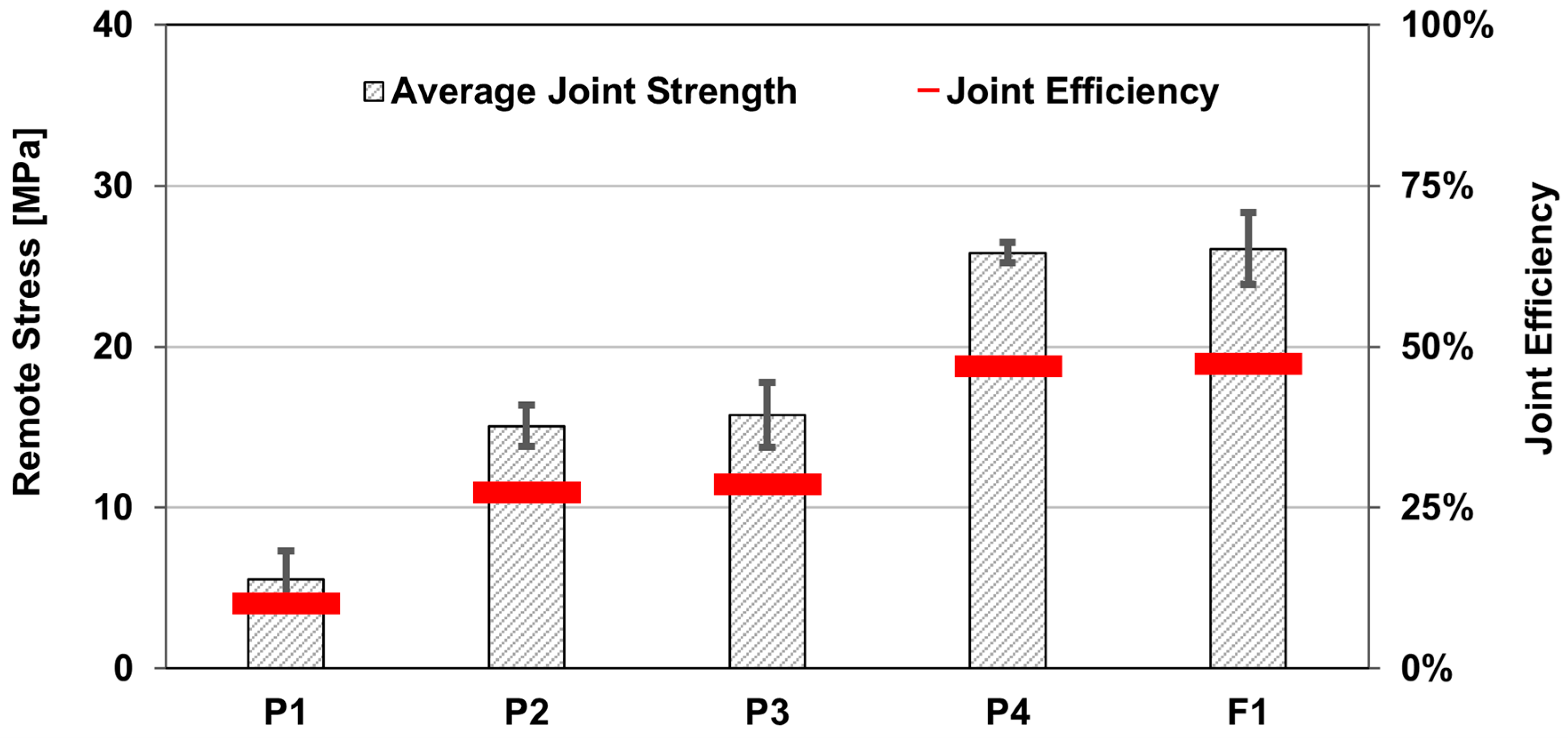
The average strength and efficiency of the dissimilar joints ranged from 5.5 to 26.1 MPa, and from 10.1% to 47.4%, respectively, as shown in
Figure 2.
The least good mechanical performance was obtained in joint P1, which was fabricated with the longest pin (4 mm) and the position-controlled process, whereas the top performance was achieved in joint F1, welded with the shortest pin (2 mm) with the force-controlled process. Even so, the analysis of joint P4, also fabricated with a pin length of 2 mm but with the position-controlled process, revealed a comparable mechanical performance to joint F1 by reaching a UTS of 25.8 MPa, equating to a joint efficiency of 47%. Moreover, joint P4 evidenced the lowest standard deviation among the tested specimens, indicating a high level of repeatability of the joining process with that set of parameters, an important characteristic for industrial purposes. Joints P2 and P3, associated with intermediate pin lengths with position-controlled processes, achieved intermediate results, as well.
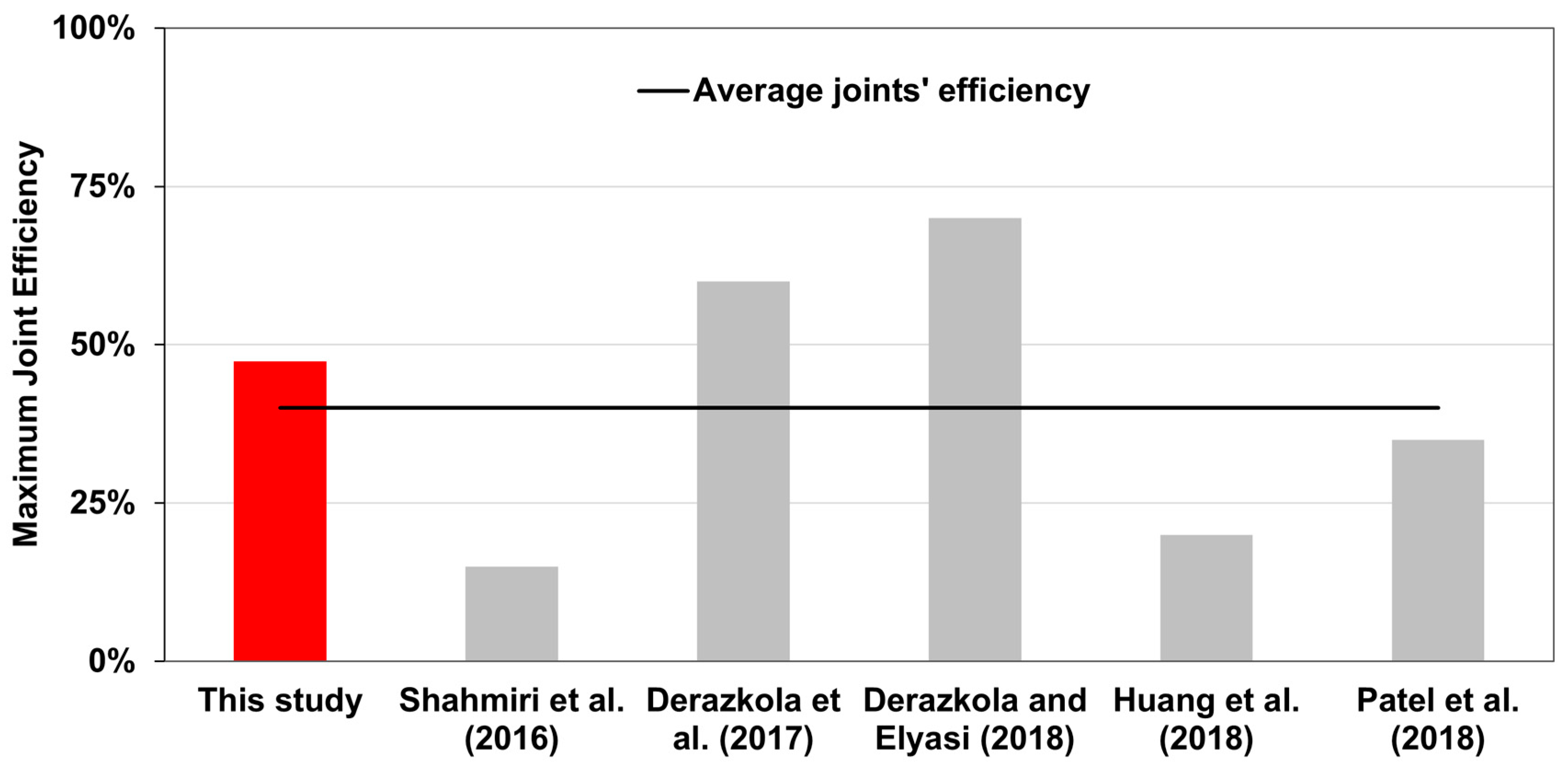
When comparing the results published in other studies that also carried out dissimilar metal-to-polymer lap joints using FSW as the joining technology [
13,
14,
15,
16,
17], it is evidenced in
Figure 3 that the average of those results was outperformed by the ones obtained in joints P4 and F1.
Considering the abovementioned data, these results not only establish the relevance of tool penetration and process control on joint morphology and mechanical strength but also further support the relevance of FSW technologies to combine such dissimilar materials.
3.2. Morphology of Joints
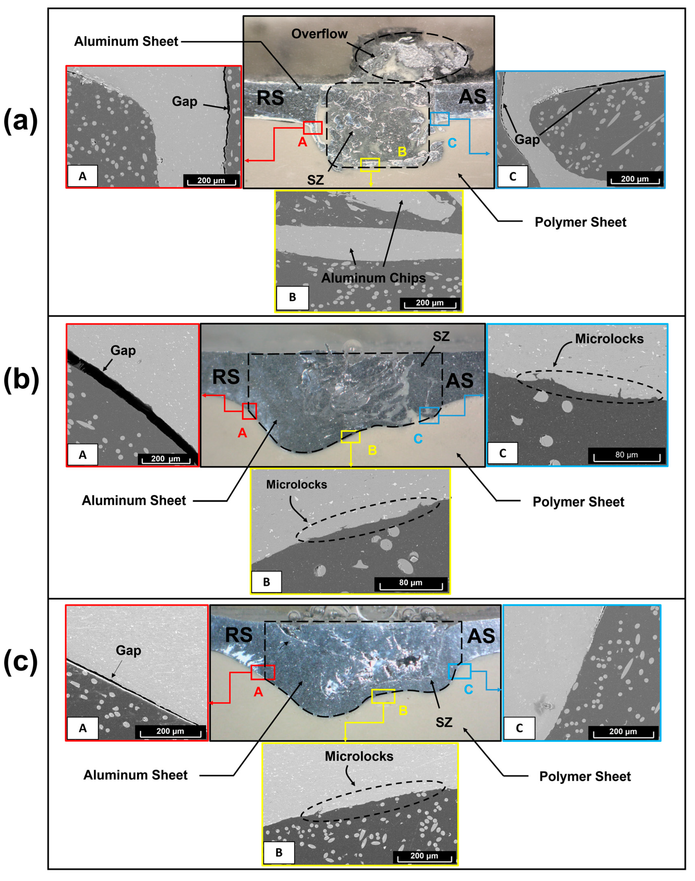
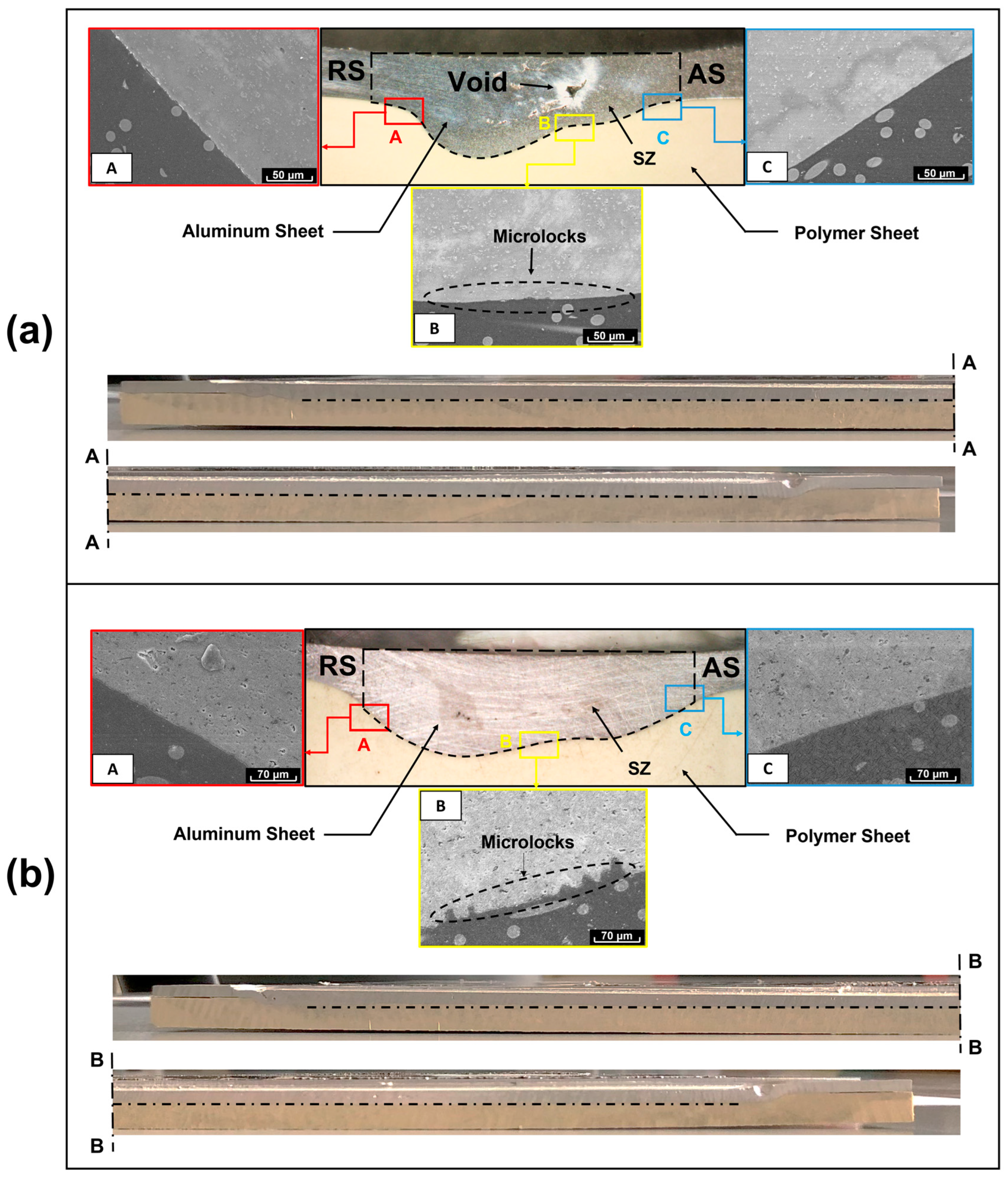
The macroscopic morphology of the joints fabricated with the controlled-position process was found to be significantly variable with the degree of penetration of the FSW tool by adjustment of the pin length. To methodically characterize the stirring zone (SZ) and the interface between the base materials, scanning electron microscopy was performed on the joining regions, as well as in three distinct locations: (i) the advancing side (AS); (ii) retreating side (RS), and (iii) weld centerline, as portrayed in
Figure 4 and
Figure 5.
Joint P1, fabricated with a pin length of 4 mm, exhibited the most heterogeneous stirring region, being composed of aluminum chips embedded within the polymeric matrix and two noticeable hook-shaped features, one on the AS and another on the RS of the joining region. These macrostructural features play a significant role in the development of the mechanical interlocking effect between the base materials, acting as the governing binding mechanism in joint P1, as identified by Huang et al. [
16], and Ratanathavorn and Melander [
23]. Nonetheless, the joint also exhibited major defects, both on macro and micro scales. The macro morphology of the SZ evidenced severe structural discontinuities in the metallic plate (highlighted in
Figure 4) with polymeric overflow throughout the welding surface, whilst the microstructure analysis revealed material gaps between the hook-shaped features and the polymeric matrix, typical defects associated with FSW of polymers, as identified by Huang et al. [
20] and Li et al. [
24]. On the one hand, the heterogenous joining region can be explained by an inappropriate stirring process, which induced excessive cutting on the aluminum plate rather than plastic deformation, a fact that, associated with the lack of vertical force due to the position-controlled process, allowed the polymeric overflow. On the other hand, the gaps observed between the base materials might be explained by the significant difference in the thermal and mechanical behaviors of the base materials, enumerated in
Table 2, originating from different heating and cooling rates inducing geometrical incompatibilities at the interface between them during the joining process [
24]. The exhibited morphology, with the defects found both on the macro and micro scales, caused joint P1 to achieve the lowest mechanical performance.
Contrarily, joints P4 and F1, fabricated using a 2 mm long pin with both the position and force-controlled processes, were revealed to be the ones with the top mechanical strength. From a visual inspection of the surface of the weld seams and corresponding cross-sections, a few minor defects such as voids were observed, even though those did not have a significant impact on mechanical performance. The SZ macro-morphology of these joints evidenced an appreciably different and wider SZ compared to P1, characterized by a well-defined interface between the base materials and exhibiting two pronounced concavities that induced macro-mechanical interlocking between the base materials, a morphology also observed by Correia et al. [
9].
From the scanning, it was observed that both joints had a clear SZ interface with no physical mixture between the base materials, nor defects, increasing the effective area of contact within the joining region, and positively affecting the chemical adhesion effect between the aluminum and polymeric plates. Furthermore, joints P4 and F1 exhibited micro-geometrical features, visible in
Figure 5, mostly in the central portion of the SZ, which enabled micro-mechanical interlocking, therefore providing a positive impact on the mechanical strength of the joints.
The joining process associated with both joints P4 and F1 evidenced very stable behavior, characterized by the linear shape of the interface between the base materials in the welding direction, also portrayed in
Figure 5.
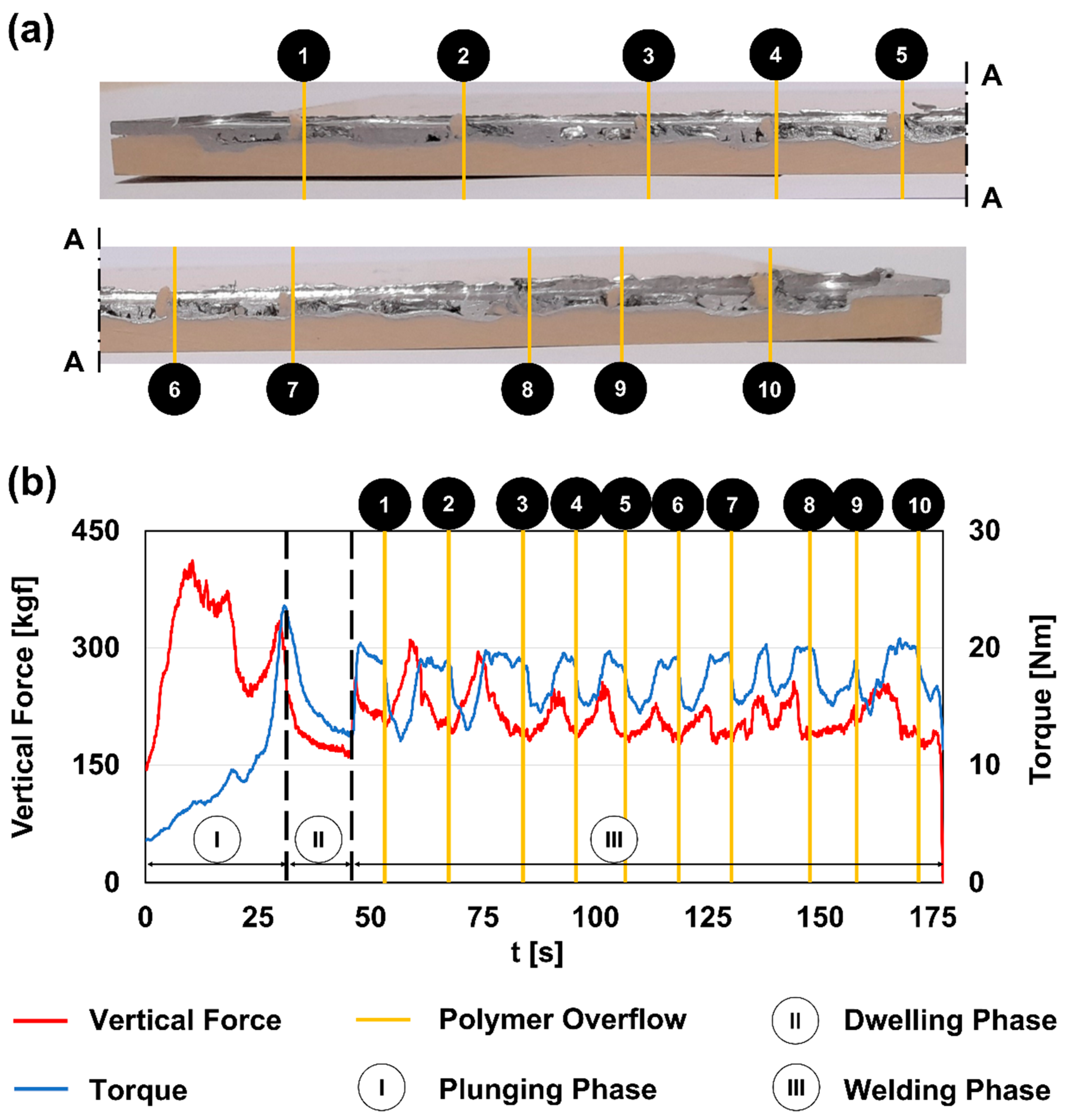
Concerning joints P2 and P3, fabricated with pin lengths of 3 and 2.5 mm, respectively, the joining region associated with these joints can be described as having an intermediate morphology between those evidenced by P1 and P4/F1. The stirring region is characterized by a well-defined interface between the base materials with a double-concavity shape, as found in joints P4/F1. However, the SZ also revealed a fragmented morphology with many voids in the aluminum side of the joint, evidencing similarities with joint P1. In addition, these joints revealed localized spots of polymeric overflow on their weld seams’ surfaces, instead of the continuous overflow observed in joint P1. This noticeable feature was, most likely, the trigger factor that explains the irregular shape of the interface between the base materials in the longitudinal direction (identified and numbered from 1 to 10 in
Figure 6), a fact that can be correlated with an unstable behavior of the joining process with this combination of welding parameters and control method.
The polymeric overflow occurred in periods of time in which the vertical force and the torque delivered to the welding process were at low and high levels, respectively. This occurrence may have resulted from the interaction between the imposed condition to keep the vertical position of the welding tool while adjusting the vertical force and torque to cope with the reaction forces generated by base material flow induced by the pin lengths of 2.5 and 3 mm. In terms of joining mechanisms, it was observed that they were identical to the ones observed in joints P4/F1, both on macro and micro scales. Yet, similarly to joint P1, gaps between the base materials in the retreating side of the joining region were observed, jeopardizing the mechanical performance of the joints due to a decreased effective area of contact within the joining region, resulting in intermediate levels of ultimate tensile strengths.
3.3. Failure Mechanisms
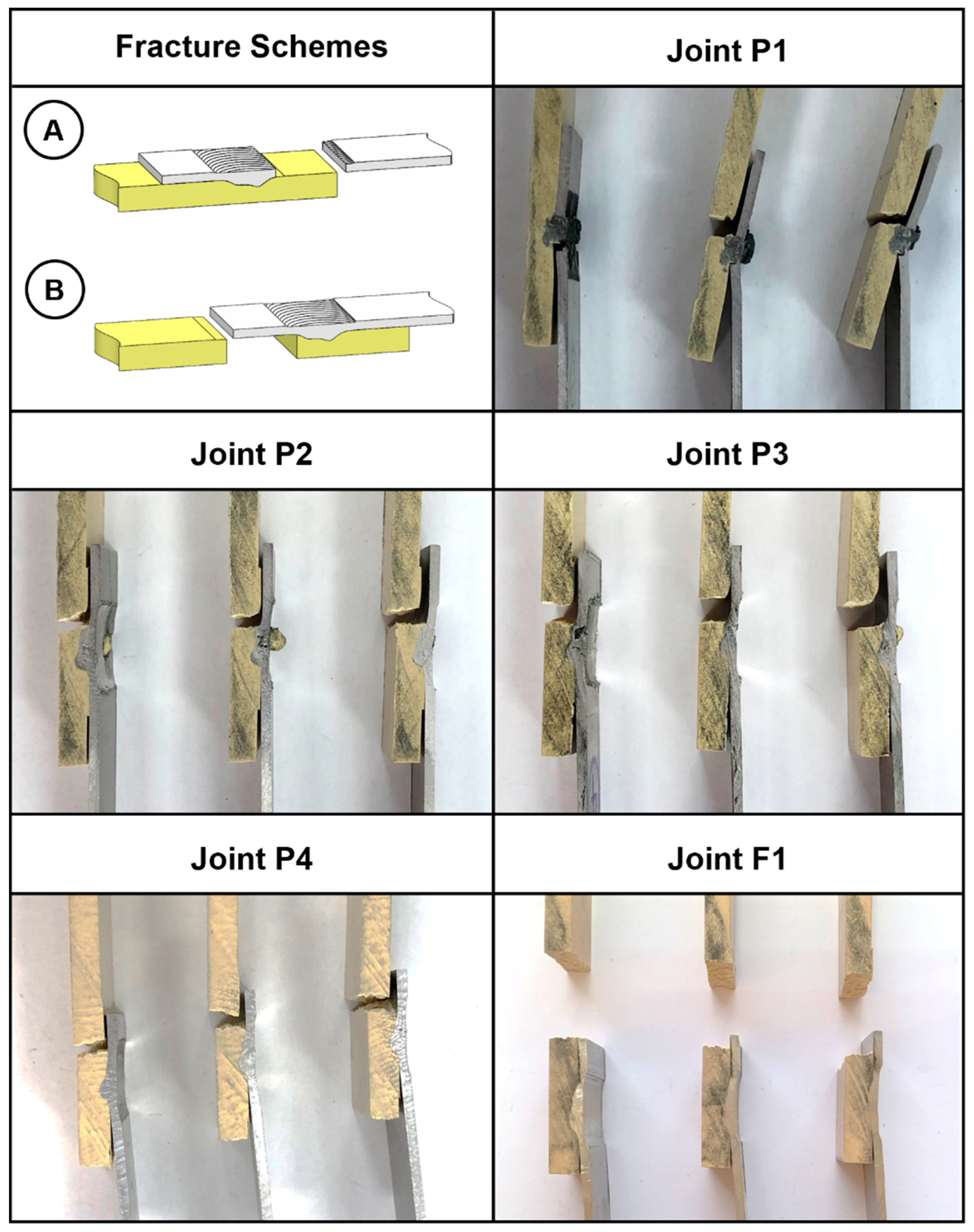
The quasi-static lap shear tensile tests ended up unveiling three distinct failure mechanisms of the specimens. These failure mechanisms can be segmented into two main mechanisms, identified as Types A and B (
Figure 7), and a third one designated by Type C, which exhibits a combination of characteristics associated with failure mechanism Types A and B. The specimens resulting from joint P1 exhibited failure mechanisms of Types A and C, whilst the specimens associated with all the other joints experienced fractures that can be associated with Type B failure mechanisms, as evidenced in
Figure 7.
Since joint P1 evidenced the lowest average tensile lap shear strength, one can associate failure mechanism Types A and C to joints with poor mechanical performance, whereas Type B can be associated with mid- to high-performing joints, i.e., P2, P3, P4, and F1.
The failure mechanism associated with Type A is characterized by the nucleation of a fracture located at the interface between the metal and the re-solidified polymer, close to the anchor-shaped features located in the retreating side of the joints. As previously mentioned, gaps between the base materials were observed along the anchoring features due to asymmetric thermal and mechanical behaviors between them, making these locations prone to crack initiation during the quasi-static tensile tests. After nucleation, the crack promptly propagates along the existing gap until the final fracture, which is characterized by the detachment of the aluminum end of the specimen, a behavior also reported by Huang et al. [
16], and Ratanathavorn and Melander [
23].
Concerning failure mechanism Type B, the crack nucleation develops in the region where a significant change in stiffness occurs, specifically between the stirring region and the polymeric end of the specimens, on the advancing side of the joint. This phenomenon results from the development of a secondary bending moment induced by the existing offset between the aluminum and the polymeric plates’ neutral lines, as described by Ekh et al. [
25] and Skorupa et al. [
26]. The secondary bending moment will generate an amount of stress that is superimposed on the remote stress associated with the tensile test loading, resulting in localized stress levels that become higher than the ultimate tensile strength of the polymer, leading to crack initiation. Subsequently, the crack grows along the thickness of the polymeric plate until the complete specimen fractures.
The failure mechanism denominated Type C can be defined as a mixed failure mechanism in which one can distinguish the development of failure attributes that are characteristic of failure mechanism Types A and B. This way, the specimens that exhibit failure mechanism Type C revealed two sites with crack nucleation, one at each end of the joining region. On the retreating side, the crack nucleated close to the anchoring feature and propagated across the aluminum plate, as happens in failure mechanism Type A, without fully fracturing the specimen. On the advancing side, a complete fracture of the polymeric end was found, and it was located on the polymeric end of the joint, as characterized by failure mechanisms associated with type B.
4. Conclusions
The present research work substantiates the feasibility of joining an aluminum alloy with a glass fiber-reinforced polymer using FSW as the joining technology. The assessment of the joining process encompassed an analysis of the effects of the tool penetration, by adjusting the pin length between 2 and 4 mm, and the process control, either a position or force-controlled process, on joints’ mechanical strength and morphology.
The average ultimate tensile strength ranged from 5.5 to 26.1 MPa, equating to joint efficiencies between 10.1 and 47.4%, illustrating the advantages of using such technologies to fabricate hybrid metal-to-polymer joints. The experimental procedures resulted in the following conclusions:
The selection of adequate welding parameters, including pin length and process control, enabled the fabrication of joints with mechanical performance above the average found in the literature;
The main binding phenomenon between these base materials is mechanical interlocking, either on the macro or micro scale, with chemical adhesion playing a secondary role;
Joint strength is highly affected by the pin length, since higher values of this variable resulted in stirring zones morphologies that may be more prone to crack initiation and growth, such as voids and gaps, thus limiting the mechanical performance;
Friction stir welding process control has a considerable effect on the repeatability of the joining process. Both position- and force-controlled processes enable the fabrication of highly efficient joints, but the ones welded with the position-controlled process evidenced a considerable decrease in the variability of results.
Adding up all the above, it can be concluded that dissimilar metal-to-polymer joints fabricated by FSW require a balance between the welding parameters and the control method to induce a stable and repeatable joining process, leading to joint morphologies that are associated with high mechanical strength and efficiency.

 ,
, 


