
Dynamic Analysis of the Thermo-Deformation Treatment Process of Flat Surfaces of Machine Parts

 , , ,
, , ,  ,
, 
Abstract
:1. Introduction
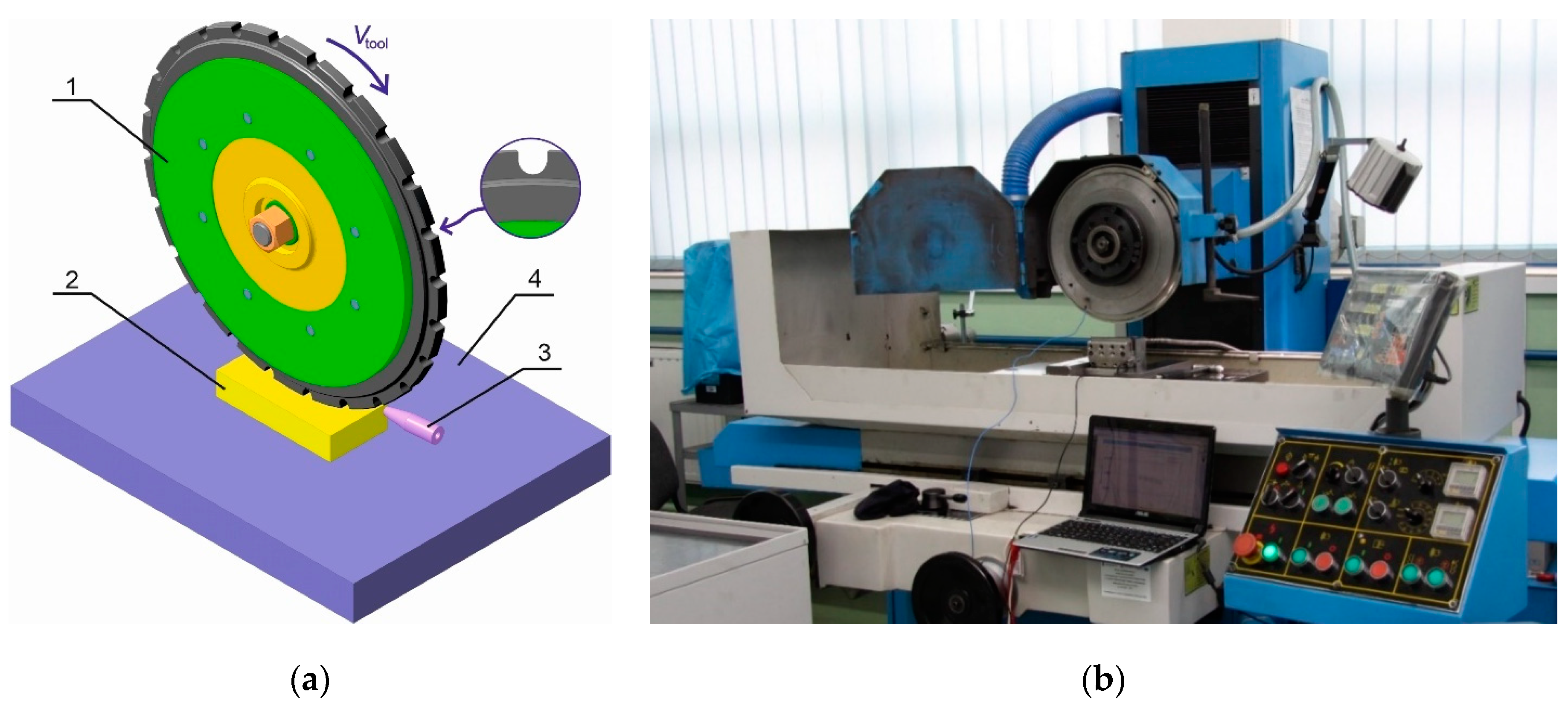
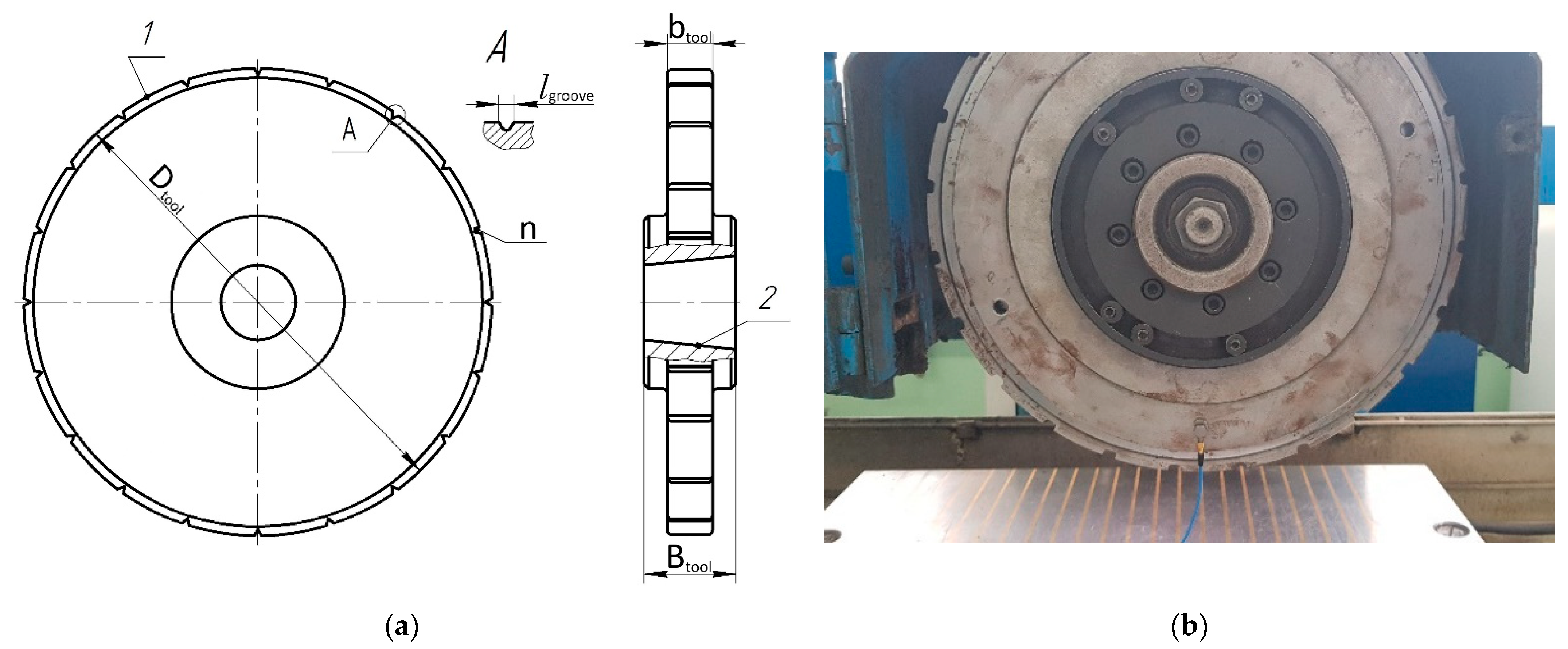
2. Materials and Methods
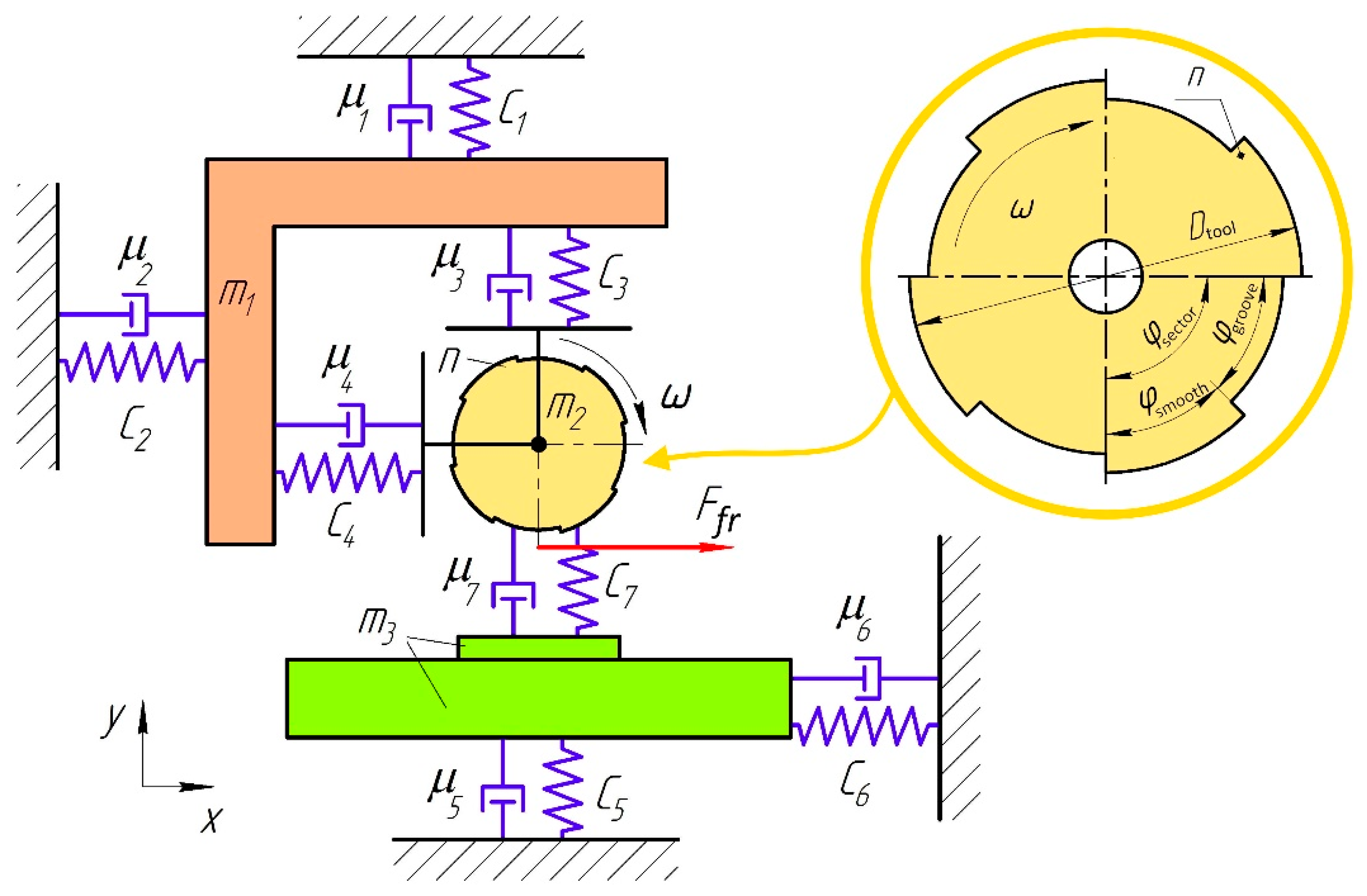
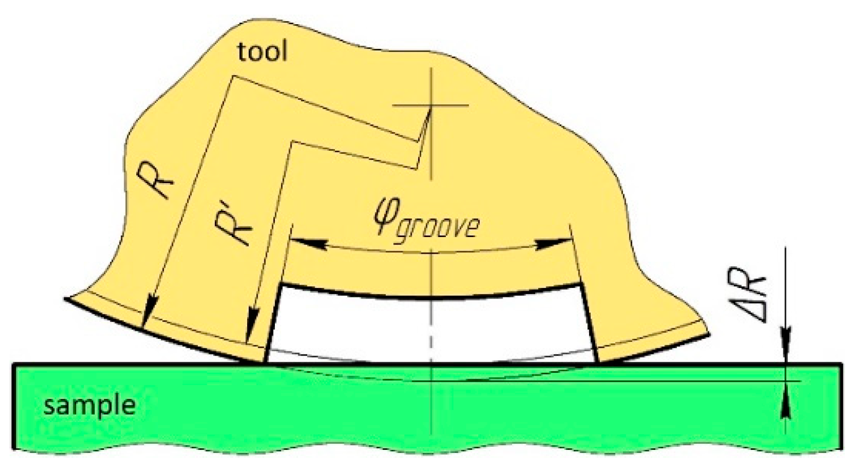
Mathematical Model
- -
- for the spindle head with the mass :
- -
- for the tools with the mass :
- -
- for the parts (workpiece) with the mass : .
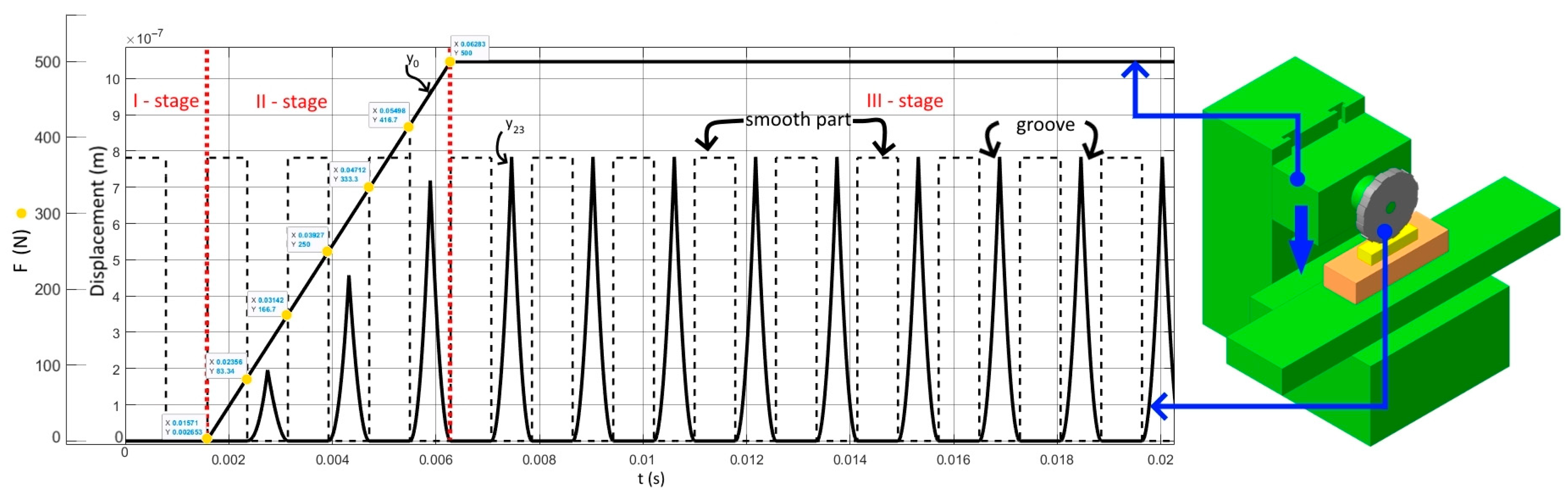
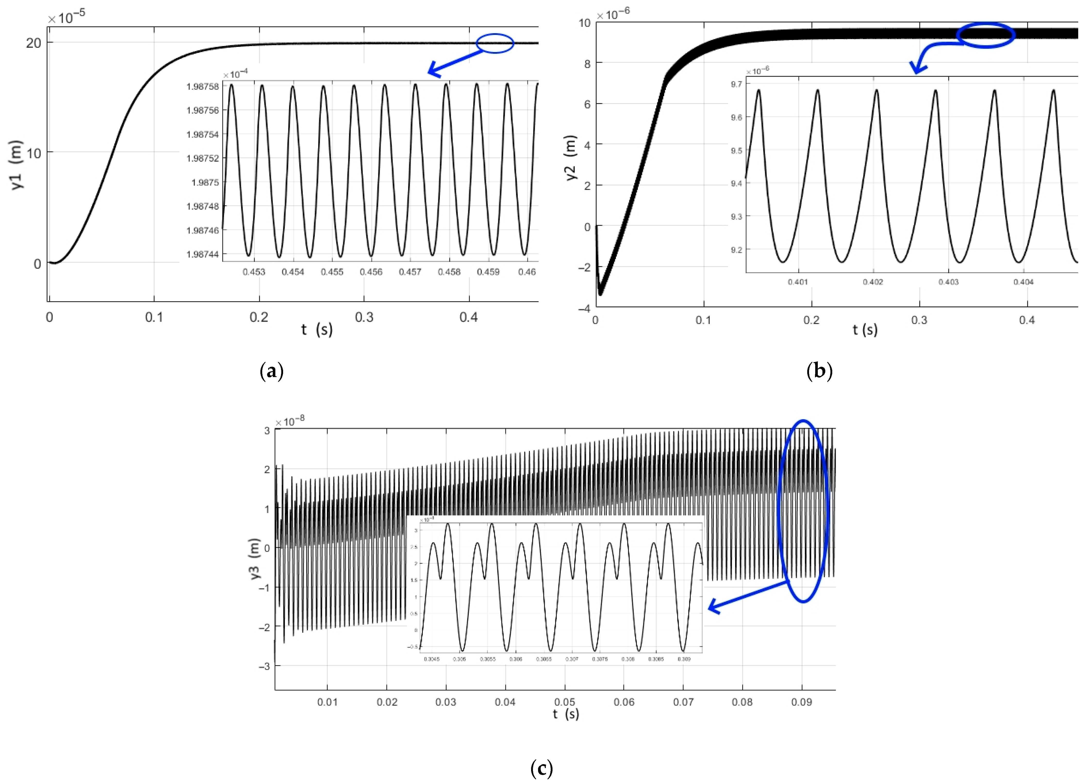
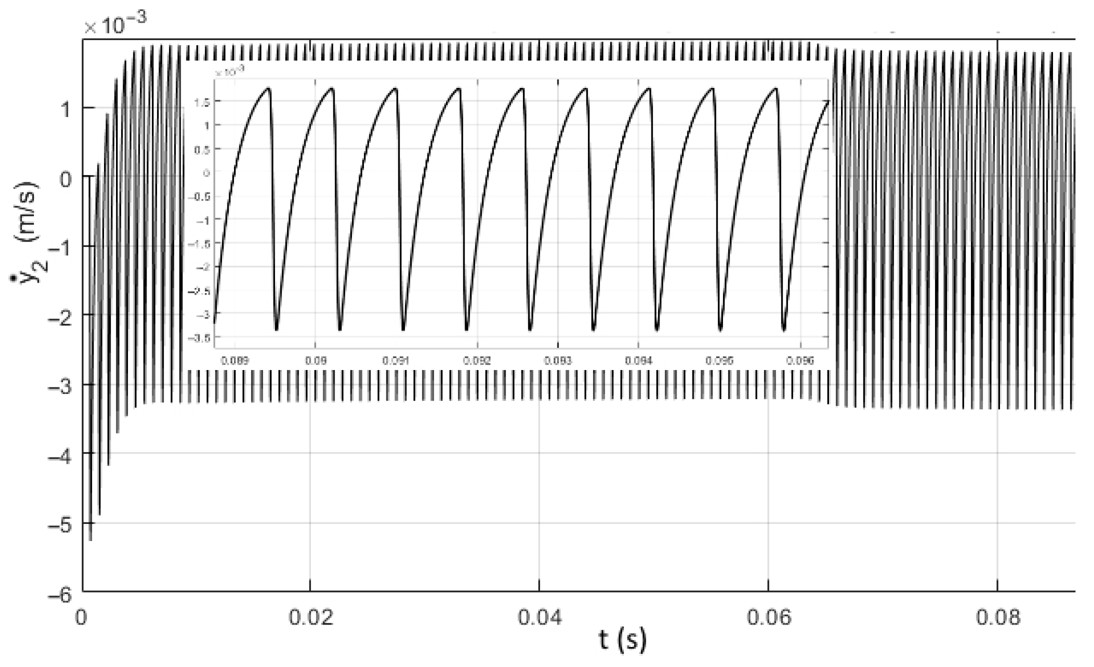
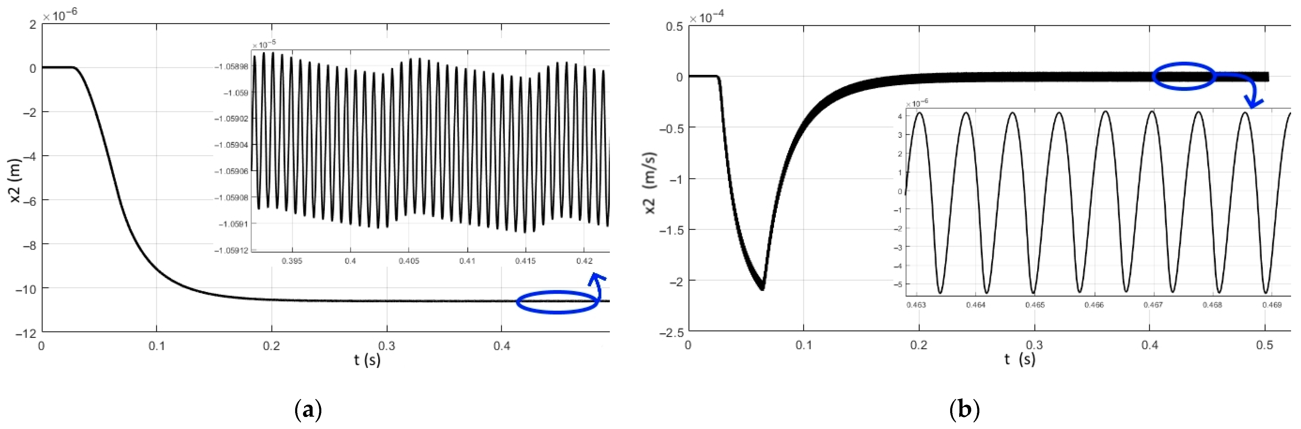
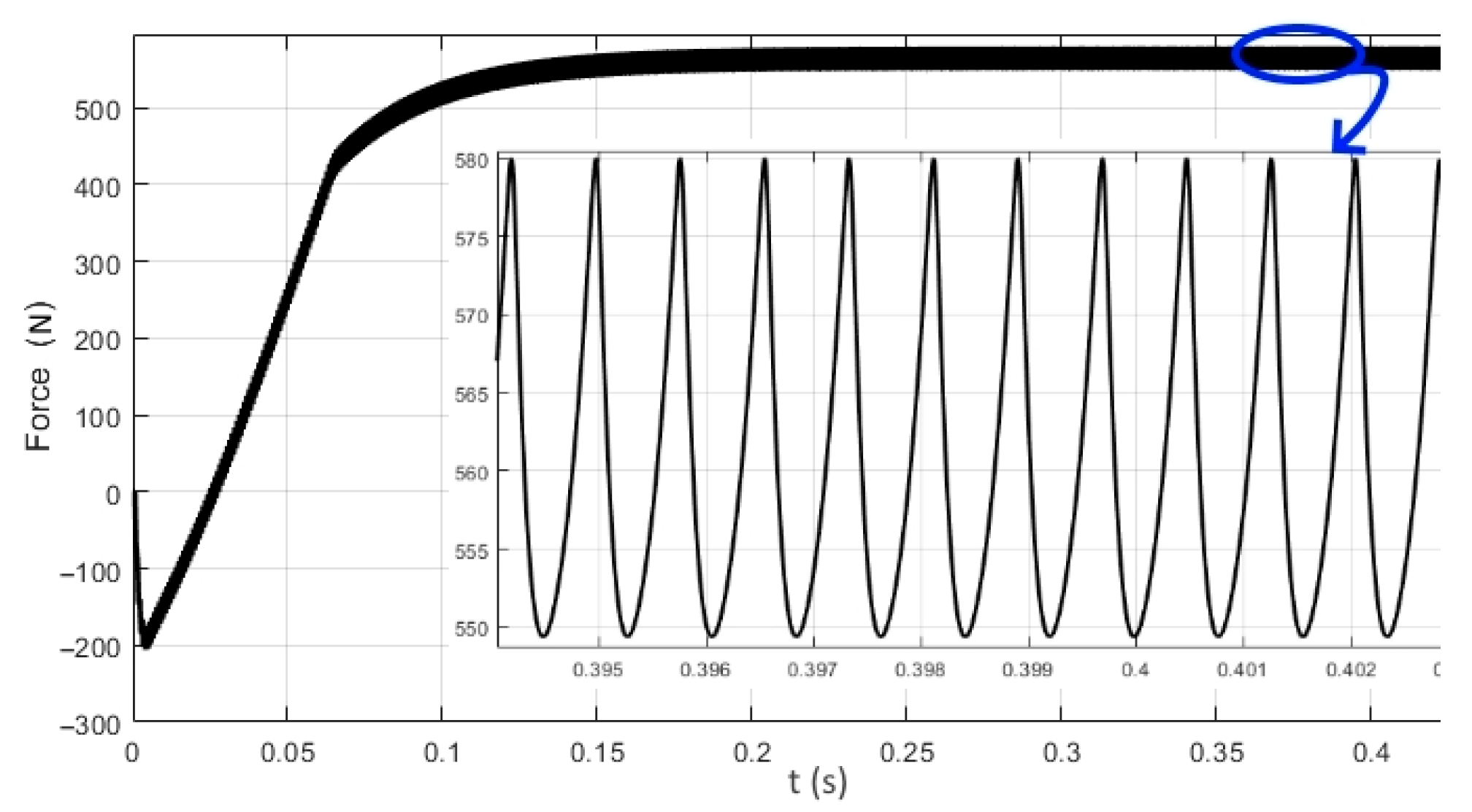
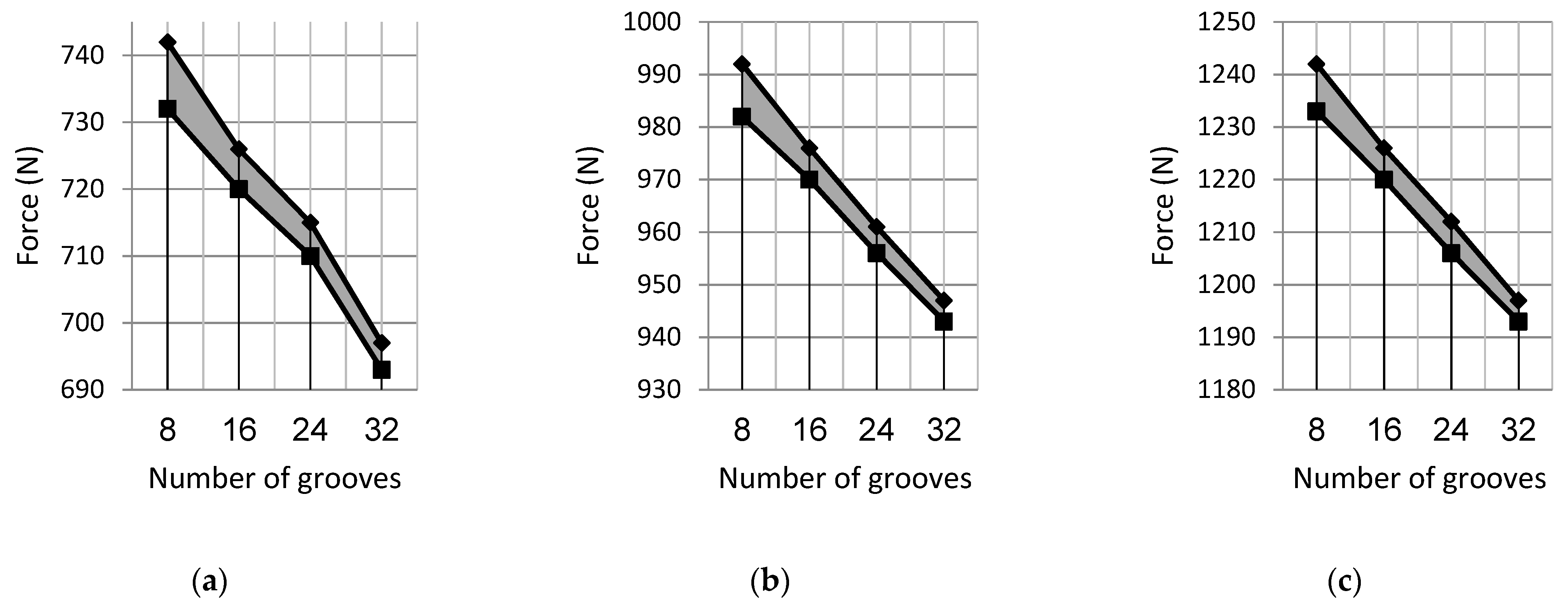
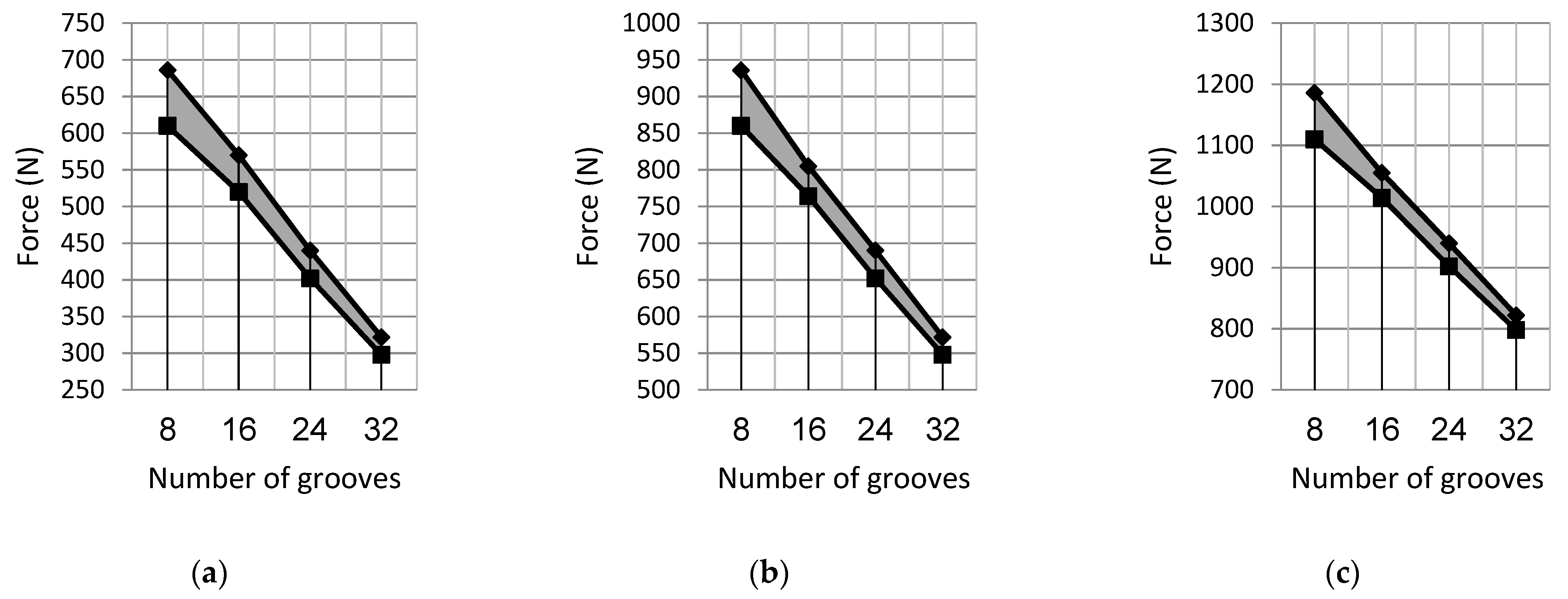
3. Results
4. Conclusions
Author Contributions
Funding
Data Availability Statement
Conflicts of Interest
References
- Davis, J.R. Surface Engineering for Corrosion and Wear Resistance; ASM International: Geauga County, OH, USA, 2001; ISBN 0-87170-700-4. [Google Scholar]
- Dwivedi, D.K. Surface Engineering: Enhancing Life of Tribological Components; Springer: New Delhi, India, 2018; ISBN 978-81-322-3777-8. [Google Scholar]
- Troshchenko, V.T. Deformation and Destruction of Metals under Multicycle Loading; Naukova Dumka: Kyiv, Ukraine, 1981. [Google Scholar]
- Pineau, A.; McDowell, D.L.; Busso, E.P.; Antolovich, S.D. Failure of Metals II: Fatigue. Acta Mater. 2016, 107, 484–507. [Google Scholar] [CrossRef]
- Santecchia, E.; Hamouda, A.M.S.; Musharavati, F.; Zalnezhad, E.; Cabibbo, M.; El Mehtedi, M.; Spigarelli, S. A Review on Fatigue Life Prediction Methods for Metals. Adv. Mater. Sci. Eng. 2016, 2016, 9573524. [Google Scholar] [CrossRef]
- Melters, P.M. Introduction to Metal Fatigue; Aarhus University: Arhus, Denmark, 2018; ISBN 2245-4594. [Google Scholar]
- Troshchenko, V.T.; Khamaza, L.A. Stages of Fatigue Failure of Metals and Alloys. Rep. Natl. Acad. Sci. Ukr. 2018, 2, 56–63. [Google Scholar] [CrossRef]
- Yushchenko, K.A.; Borysov, Y.S.; Kuznetsov, V.D.; Korzh, V.M. Surface Engineering; Naukova Dumka: Kyiv, Ukraine, 2007. [Google Scholar]
- Gurey, V.; Hurey, I. The Effect of the Hardened Nanocrystalline Surface Layer on Durability of Guideways. In Proceedings of the Lecture Notes in Mechanical Engineering; Tonkonogyi, V., Ivanov, V., Trojanowska, J., Oborskyi, G., Edl, M., Kuric, I., Pavlenko, I., Dasic, P., Eds.; Springer International Publishing: Cham, Switzerland, 2020; pp. 63–72. [Google Scholar]
- Gurey, V.; Hurey, I.; Hurey, T.; Wojtowicz, W. Fatigue Strength of Steel Samples After Friction Treatment. Lect. Notes Mech. Eng. 2023, 1, 274–283. [Google Scholar] [CrossRef]
- Kyryliv, V.I.; Gurey, V.I.; Maksymiv, O.V.; Hurey, I.V.; Kulyk, Y.O. Influence of the Deformation Mode on the Force Conditions of Formation of the Surface Nanostructure of 40Kh Steel. Mater. Sci. 2021, 57, 422–427. [Google Scholar] [CrossRef]
- Shaw, L.L. The Surface Deformation and Mechanical Behavior of Nanostructured Alloys. In Nanostructured Metals and Alloys; Elsevier: Cambridge, UK, 2011; pp. 481–506. ISBN 9781845696702. [Google Scholar]
- Bartkowska, A. Production and Properties of FeB-Fe2B-Fe3(B,C) Surface Layers Formed on Tool Steel Using Combination of Diffusion and Laser Processing. Coatings 2020, 10, 1130. [Google Scholar] [CrossRef]
- Korzhyk, V.; Tyurin, Y.; Kolisnichenko, O. Theory and Practice of Plasma-Detonation Technology of Surface Hardening Metal Products; Privat Company Technology Center: Kharkiv, Ukraine, 2021; ISBN 9786177319466. [Google Scholar]
- Lukaszkowicz, K. Review of Nanocomposite Thin Films and Coatings Deposited by PVD and CVD Technology. In Nanomaterials; Rahman, M.M., Ed.; InTech: Rijeka, Croatia, 2011. [Google Scholar]
- Quintino, L. Overview of Coating Technologies. In Surface Modification by Solid State Processing; Elsevier: Cambridge, UK, 2014; pp. 1–24. ISBN 9780857094681. [Google Scholar]
- Hurey, I.; Hurey, T.; Lanets, O.; Dmyterko, P. The Durability of the Nanocrystalline Hardened Layer during the Fretting Wear. Lect. Notes Mech. Eng. 2021, 2, 23–32. [Google Scholar] [CrossRef]
- Vilaça, P. Friction Surfacing. In Surface Modification by Solid State Processing; Elsevier: Cambridge, UK, 2014; pp. 25–72. [Google Scholar]
- Zhang, F.; Duan, C.; Wang, M.; Sun, W. White and Dark Layer Formation Mechanism in Hard Cutting of AISI52100 Steel. J. Manuf. Process. 2018, 32, 878–887. [Google Scholar] [CrossRef]
- Zhang, F.; Duan, C.; Sun, W.; Ju, K. Effects of Cutting Conditions on the Microstructure and Residual Stress of White and Dark Layers in Cutting Hardened Steel. J. Mater. Process. Technol. 2019, 266, 599–611. [Google Scholar] [CrossRef]
- Javaheri, V.; Sadeghpour, S.; Karjalainen, P.; Lindroos, M.; Haiko, O.; Sarmadi, N.; Pallaspuro, S.; Valtonen, K.; Pahlevani, F.; Laukkanen, A.; et al. Formation of Nanostructured Surface Layer, the White Layer, through Solid Particles Impingement during Slurry Erosion in a Martensitic Medium-Carbon Steel. Wear 2022, 496–497, 204301. [Google Scholar] [CrossRef]
- Inoue, A.; Hashimoto, K. (Eds.) Amorphous and Nanocrystalline Materials; Advances in Materials Research; Springer: Berlin/Heidelberg, Germany, 2001; Volume 3, ISBN 978-3-642-08664-9. [Google Scholar]
- Hosseini, S.B.; Klement, U. A Descriptive Phenomenological Model for White Layer Formation in Hard Turning of AISI 52100 Bearing Steel. CIRP J. Manuf. Sci. Technol. 2021, 32, 299–310. [Google Scholar] [CrossRef]
- Gurey, V.; Shynkarenko, H.; Kuzio, I. Mathematical Model of the Thermoelasticity of the Surface Layer of Parts during Discontinuous Friction Treatment. Lect. Notes Mech. Eng. 2021, 2, 12–22. [Google Scholar] [CrossRef]
- Wu, S.; Liu, G.; Zhang, W.; Chen, W.; Wang, C. Formation Mechanism of White Layer in the High-Speed Cutting of Hardened Steel under Cryogenic Liquid Nitrogen Cooling. J. Mater. Process. Technol. 2022, 302, 117469. [Google Scholar] [CrossRef]
- Lowe, T.C.; Zhu, Y.T.; Semiatin, S.L.; Berg, D.R. Overview and Outlook for Materials Processed by Severe Plastic Deformation. In Investigations and Applications of Severe Plastic Deformation; Lowe, T.C., Valiev, R.Z., Eds.; Springer: Dordrecht, The Netherlands, 2000; pp. 347–356. ISBN 978-94-011-4062-1. [Google Scholar]
- Hahn, H. Unique Features and Properties of Nanostructured Materials. In Nanomaterials by Severe Plastic Deformation; Wiley-VCH Verlag GmbH & Co., KGaA: Weinheim, Germany, 2005; pp. 2–17. ISBN 9783527602469. [Google Scholar]
- Guo, Y.B.; Warren, A.W.; Hashimoto, F. The Basic Relationships between Residual Stress, White Layer, and Fatigue Life of Hard Turned and Ground Surfaces in Rolling Contact. CIRP J. Manuf. Sci. Technol. 2010, 2, 129–134. [Google Scholar] [CrossRef]
- Cicero, S.; Álvarez, J.A. Fracture, Fatigue, and Structural Integrity of Metallic Materials. Metals 2019, 9, 913. [Google Scholar] [CrossRef]
- Kyryliv, V.; Maksymiv, O.; Gurey, V.; Hurey, I.; Kyryliv, Y.; Zvirko, O. The Mode Deformation Effect on Surface Nanocrystalline Structure Formation and Wear Resistance of Steel 41Cr4. Coatings 2023, 13, 249. [Google Scholar] [CrossRef]
- Hurey, I.; Gurey, V.; Kyryliv, V. A Tool for Alloying the Surface Layers of Machine Parts. Patent No. 123883, 2021. [Google Scholar]
- Burek, J.; Hurey, I. Tool for Forming a Nanocrystalline Hardened Surface Layer of an Object and a Method for Forming a Nanocrystalline Hardened Surface Layer of an Object. Patent No. 240972, 2022. [Google Scholar]
- Gans, R.F. Engineering Dynamics; Springer: New York, NY, USA, 2013; ISBN 978-1-4614-3929-5. [Google Scholar]
- Timoshenko, S.; Weaver, W. Vibration Problems in Engineering; Wolfenden Press: Singapore, 2007; ISBN 978-1406774658. [Google Scholar]
- Torby, B.J. Advanced Dynamics for Engineers; Holt Rinehart & Winston: New York, NY, USA, 1984; ISBN 0-03-063366-4. [Google Scholar]
- Goldstein, H.; Poole, C.; Safko, J. Classical Mechanics, 3rd ed.; Addison Wesley: Boston, MA, USA, 2001; ISBN 9780201657029. [Google Scholar]
- Taylor, R.J. Classical Mechanics; University Science Books: Melville, NY, USA, 2005; ISBN 1-891389-22-X. [Google Scholar]


Disclaimer/Publisher’s Note: The statements, opinions and data contained in all publications are solely those of the individual author(s) and contributor(s) and not of MDPI and/or the editor(s). MDPI and/or the editor(s) disclaim responsibility for any injury to people or property resulting from any ideas, methods, instructions or products referred to in the content. |
© 2023 by the authors. Licensee MDPI, Basel, Switzerland. This article is an open access article distributed under the terms and conditions of the Creative Commons Attribution (CC BY) license (https://creativecommons.org/licenses/by/4.0/).
Share and Cite
Gurey, V.; Maruschak, P.; Hurey, I.; Dzyura, V.; Hurey, T.; Wojtowicz, W. Dynamic Analysis of the Thermo-Deformation Treatment Process of Flat Surfaces of Machine Parts. J. Manuf. Mater. Process. 2023, 7, 101. https://doi.org/10.3390/jmmp7030101
Gurey V, Maruschak P, Hurey I, Dzyura V, Hurey T, Wojtowicz W. Dynamic Analysis of the Thermo-Deformation Treatment Process of Flat Surfaces of Machine Parts. Journal of Manufacturing and Materials Processing. 2023; 7(3):101. https://doi.org/10.3390/jmmp7030101
Chicago/Turabian StyleGurey, Volodymyr, Pavlo Maruschak, Ihor Hurey, Volodymyr Dzyura, Tetyana Hurey, and Weronika Wojtowicz. 2023. "Dynamic Analysis of the Thermo-Deformation Treatment Process of Flat Surfaces of Machine Parts" Journal of Manufacturing and Materials Processing 7, no. 3: 101. https://doi.org/10.3390/jmmp7030101