Article

Study on Elucidation of the Roundness Improvement Mechanism of the Internal Magnetic Abrasive Finishing Process Using a Magnetic Machining Tool

1
Graduate School of Engineering, Utsunomiya University, 7-1-2 Yoto, Utsunomiya 321-8585, Tochigi, Japan
2
School of Engineering, Course of Mechanical Engineering Systems, Utsunomiya University, 7-1-2 Yoto, Utsunomiya 321-8585, Tochigi, Japan
*
Author to whom correspondence should be addressed.
J. Manuf. Mater. Process. 2023, 7(1), 49; https://doi.org/10.3390/jmmp7010049
Submission received: 19 January 2023 / Revised: 7 February 2023 / Accepted: 9 February 2023 / Published: 13 February 2023
(This article belongs to the Special Issue Advances in Metal Cutting and Cutting Tools)

Abstract

:
The magnetic abrasive finishing process using the magnetic machining tool was proposed to finish the internal surface of the thick tube (the thickness of the tube is 5~30 mm). It has been proved that this process can improve the roundness while improving the roughness. In this paper, we mainly study the machining mechanism of roundness improvement. Firstly, the influence of finishing characteristics on the roundness improvement was discussed, including the rotational speed of the magnetic machining tool and the rotational speed of the tube. It was concluded that the roundness improvement increases with the increase in the rotational speed through the analysis of finishing force and finishing times. Furthermore, the influence on roundness improvement of different distributions of magnetic particles were experimentally compared. After finishing, due to the magnetic force generated by the magnetic machining tool and the magnetic pole unit exerting pressure on the magnetic particles, a fixed magnetic brush is formed. The experimental results show that the circumferential length of the fixed magnetic brush is different due to the different distribution areas of magnetic particles. It was concluded that the roundness improvement increases with the circumferential length of the fixed magnetic brush increases by discussing the relationship between the circumferential length of the fixed magnetic brush and the wavelength of the roundness curve. When the circumferential length of the fixed magnetic brush is 76 mm, the roundness was improved from 379 μm to 236 μm after 60 min of finishing.

1. Introduction

With the development of the semiconductor and aerospace industries, the high precision of parts is required, meanwhile the innovation of processing technology is also required. Magnetic abrasive finishing (MAF) is a precision processing technology in which the finishing force is generated via a magnetic field. Magnetic particles form magnetic brush under the action of magnetic force, and then the tube is finished by abrasive particles through the relative motion with the magnetic brush [1,2,3,4,5]. Magnetic field-assisted finishing includes nontraditional and finishing techniques that enhance both the surface quality and integrity of machined components. Among such techniques, magnetic abrasive finishing (MAF) can play a major role in micro-/nano-finishing, since it uses a magnetic field to force magnetic abrasive particles and abrasives onto a workpiece, improving the quality of the polished surface [6,7]. Furthermore, the process of MAF can also realize the finishing of the plane, cylindrical outer surface and deburring. Shinmura et al. studied the basic principle and finishing characteristics of MAF and developed a plane magnetic finishing device using a stationary type electromagnet; it was verified that this process can achieve precision finishing of the plane [8,9,10]. Furthermore, in recent studies, Zou et al. developed the magnetic abrasive finishing process using an alternating magnetic field and the influence of magnetic particle size and magnetic field frequency on magnetic cluster changes was observed, and the relationship between the finishing force and alternating magnetic field was analyzed [11,12,13]. Moreover, the development of a new magnetic abrasive finishing process with renewable abrasive particles using the circulatory system and the influence of important process parameters, including the magnetic particles, abrasive particles, conveyor belt line speed and the working gap on the surface quality of the workpiece are studied through the experiment [14,15]. Yamaguchi et al. developed an internal magnetic abrasive finishing process for the nonferromagnetic complex-shaped tubes consisting of straight and bent sections, and developed a multiple pole-tip system using a partially heat-treated magnetic tool, allowing the finishing of multiple regions simultaneously in capillary tubes and thus improving the finishing efficiency [16,17,18]. Yin et al. studied the polishing characteristics and the mechanisms of three vibration modes in vibration-assisted magnetic abrasive polishing, using this process to deburr for the magnesium alloy, concluding that the deburring efficiency considerably increases with vibration assistance [19,20].
Moreover, there are many studies on the internal surface finishing process using the finishing force generated via the magnetic field. Kim et al. developed an internal polishing system using magnetic force for the production of ultra-clean tubes that apply the magnetic abrasives composed of WC/Co powder and studied the optimal conditions and machining characteristics [21]. Jain et al. developed a new precision finishing process called magnetorheological abrasive flow finishing (MRAFF), which is basically a combination of abrasive flow machining (AFM) and magnetorheological finishing (MRF) and has been developed for the nano-finishing of parts, even those with complicated geometry, for a wide range of industrial applications [22,23,24]. Zou et al. developed a new efficient internal finishing process for a non-ferromagnetic thick tube via the application of a magnetic field-assisted machining process using a magnetic machining jig. They concluded that this process enables precise internal finishing of the thick non-ferromagnetic tubes, such as the SUS304 stainless steel tube of 10 mm in thickness [25]. They also developed a new internal finishing process for tubes, which is the magnetic abrasive finishing process combined with electrochemical machining, and they concluded the surface finishing by the removal of the pits and finishing time is reduced [26]. Chen et al. developed the magnetic finishing with gel abrasive (MFGA) applying gels mixed with steel grit and abrasives to improve the polishing efficiency and surface uniformity of the steel elements, and it was concluded that since guar gum had better fluidity than the silicone gel did and that guar gum created excellent polishing efficiency in MFGA [27,28,29].
In the previous studies, the changing process of roundness has been analyzed and it was concluded that as the thickness of tube increases, the roundness improvement decreases [30]. In addition, the influence of thee reciprocating velocity of the magnetic pole unit on the improvement in the roundness of the interior surface was studied by establishing the dynamic equation of the magnetic machining jig. Experimental results showed that a low reciprocating velocity for the magnetic pole unit is conducive to the improvement of the internal roundness of the thick SUS304 stainless steel tube [31]. However, the mechanism of the influence of other parameters on roundness improvement has not been discussed. In order to further clarify the mechanism of roundness improvement in this process, in this paper, firstly, the influence of rotational speed was discussed by the analysis of the finishing force generated by magnetic machining tool. Then the influence of the distribution of magnetic particles on the roundness improvement of the magnetic machining tool was analyzed. Due to the pressure generated via the magnetic force of the magnetic machining tool and the magnetic pole unit, the magnetic particles form a fixed shape magnetic brush. The influence of the circumferential contact arc between the fixed magnetic brush and internal surface of the tube was discussed.

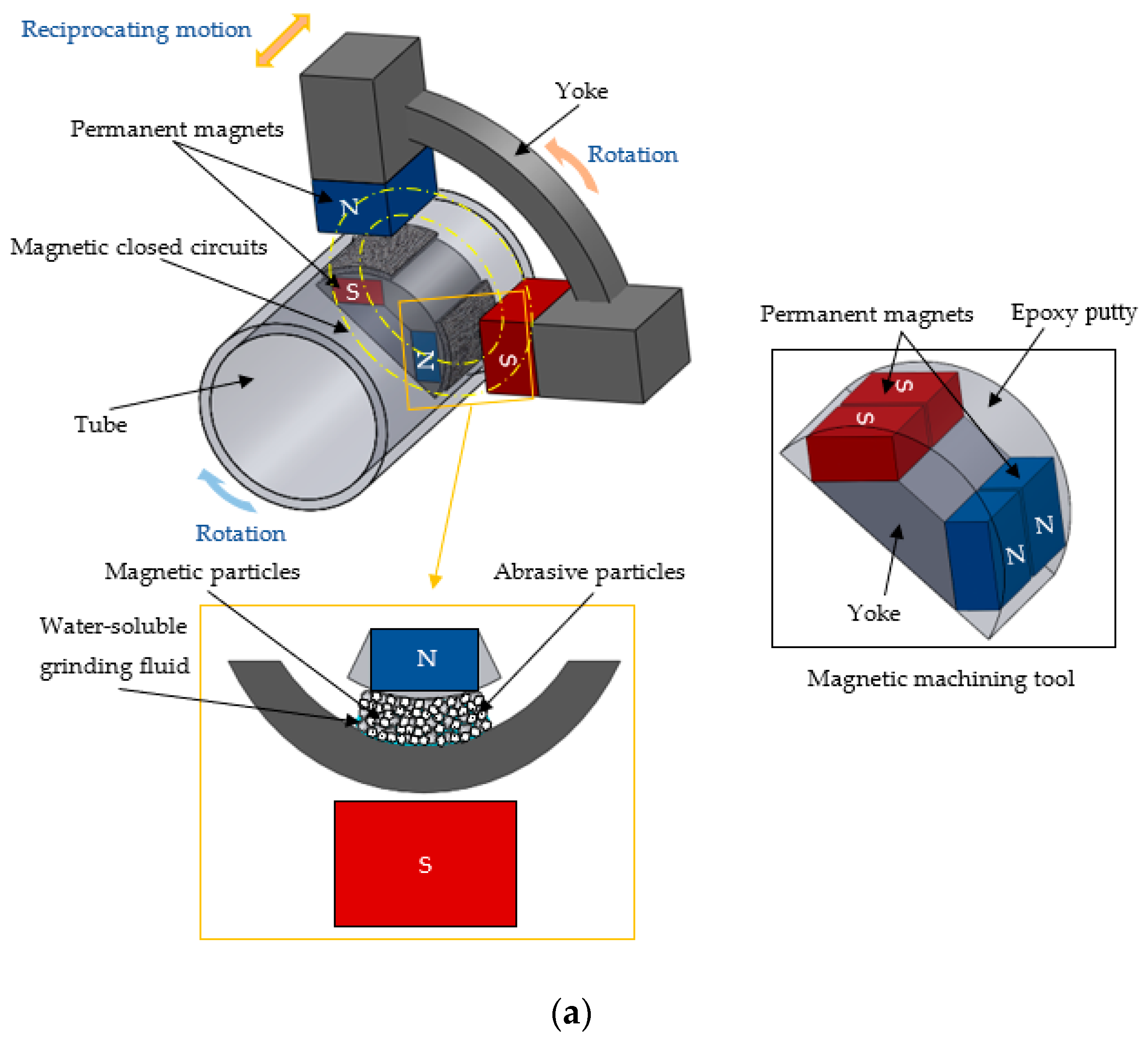
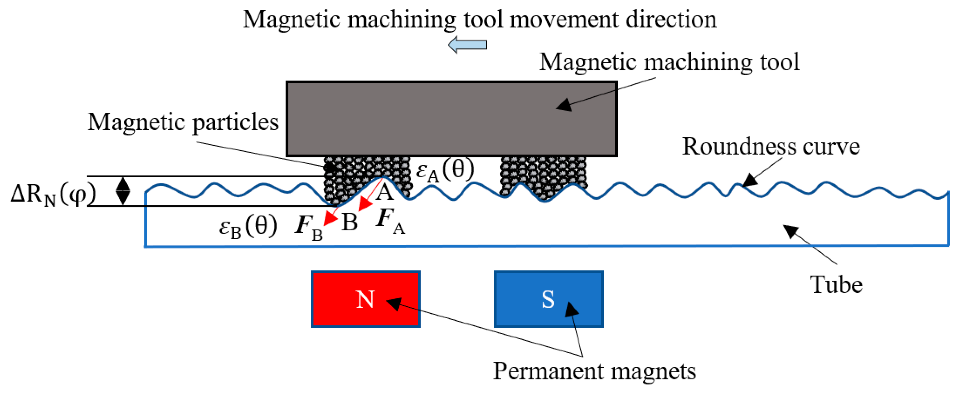
2. Processing Principle

The schematic of the internal magnetic abrasive finishing process using a magnetic machining tool is shown in Figure 1a. The magnetic machining tool consists of a yoke and two pairs of permanent magnets (Nd–Fe–B magnet). Then, the epoxy putty is covered to conform to the shape of the internal surface of the tube. Additionally, in order to prevent collision during finishing, the magnetic machining tool is wrapped with non-woven fabric. Magnetic particles are attracted to the surface of the magnet machining tool via magnetic force. After the magnetic machining tool is put into the internal surface of tube, it is attracted by the permanent magnets (Ferrite magnet) of the magnetic pole unit outside the tube and forms magnetic closed circuits that generate a high magnetic force as the finishing force. When the magnetic machining tool rotated with the rotation of the magnetic pole unit, it generated the relative motion between the magnetic particles and the tube. In this process, the abrasive slurry mixed with the abrasive particles and water-soluble grinding fluid in a certain proportion is used to achieve a high-quality surface. Therefore, the finishing force is indirectly transferred from the magnetic particles to the abrasive particles. Moreover, when the magnetic pole unit outside the tube is driven in the direction of the tube axis while rotating, the high-precision finishing of the entire internal surface of the tube can be achieved.
This process is realized by the magnetic particles being attracted by the magnetic force on the surface of the magnetic machining tool, so the magnetic machining tool and the magnetic particles are regarded as a whole for force analysis. In addition, the magnetic machining tool and the magnetic poles outside the tube also generate the magnetic attraction force. Figure 1b shows the force analysis model diagram of the magnetic machining tool. F y is the magnetic attraction force generated by the magnetic machining tool and the magnetic poles outside the tube. F x is the magnetic force generated by the magnetic machining tool and magnetic poles outside the tube in the direction of equipotential lines. F c is the centrifugal force generated by the rotation of the magnetic machining tool. G is the gravity including the gravity of magnetic machining tool and magnetic particles. F f is the frictional resistance generated during finishing. Figure 2 shows the straight-line expansion of the internal surface of the tube along the circumference direction. ε A θ and ε B θ are the removal amounts at point A and point B, and the removal amount is proportional to the finishing force. According to the evaluation method of roundness, it can be seen that when the ε A θ becomes smaller, it is beneficial to improve the roundness. Therefore, in this process the magnetic particles were also affected by the pressure generated by the magnetic force, resulting in the finishing force mainly being concentrated at point A and a little finishing force acting on point B, which is beneficial to the roundness improvement. Therefore, this process can improve the roundness while improving the roughness.

3. Experimental Setup

The external view of the experimental setup is shown in Figure 3. The experimental setup consists of the tube clamping unit (three-claw chuck, tailstock and top) and the magnetic pole unit (permanent magnets, ball screw, linear slide, position switch and reciprocating table). The magnetic pole unit, including four permanent magnets (50 × 35 × 26 mm) connected to the yoke, is set up on the reciprocating table. Therefore, the magnetic pole unit can be driven in the direction of the tube axis during rotation. Additionally, the permanent magnets are arranged N–S–S–N at a 90° interval toward the tube center, and the distribution of magnets is flexible for various tube diameters. At the same time, the tube also rotated to generate relative motion with the magnetic unit. This setup can realize three motions: the rotation of the tube and the rotation and reciprocating motion of the magnetic pole unit, so it can finish the complete internal surface of the tube.

4. Influence of Rotational Speed

In the internal magnetic abrasive finishing using the magnetic machining tool process, not only does the magnetic machining tool rotate, but the tube also rotates, and the rotation direction is opposite, so that the tangential finishing force is generated by the relative motion between the magnetic machining tool and the tube. In order to study the influence of rotational speed on roundness improvement, experiments were carried out under the conditions of different rotational speeds of the magnetic machining tool and different rotational speeds of the tube.

4.1. Rotational Speed of the Magnetic Machining Tool

4.1.1. Experimental Conditions and Method

The experimental conditions are shown in Table 1. The SUS 304 stainless steel tube was used as workpiece. In order to study the influence of the rotational speed of the magnetic machining tool (equal to the rotational speed of magnetic pole unit), the rotational speed of the tube is the same (66 rpm), while the rotational speed of the magnetic machining tool is 32 rpm, 123 rpm and 215 rpm, respectively. The finishing time is 100 min; to understand the changes in roundness, surface roughness and material removal, each stage finishing time is 20 min, and then the tube is cleaned with ultrasonic cleaner and measured with the surface roughness meter (SURFPAK-PRO produced by Mitutoyo, Japan), the roundness measuring instrument (RONDCOM 40C produced by TOKYO SEIMITSU, Japan) and the balance PR8001 (SHIMADZU, Japan, minimum weighing unit: 0.1 g), respectively.

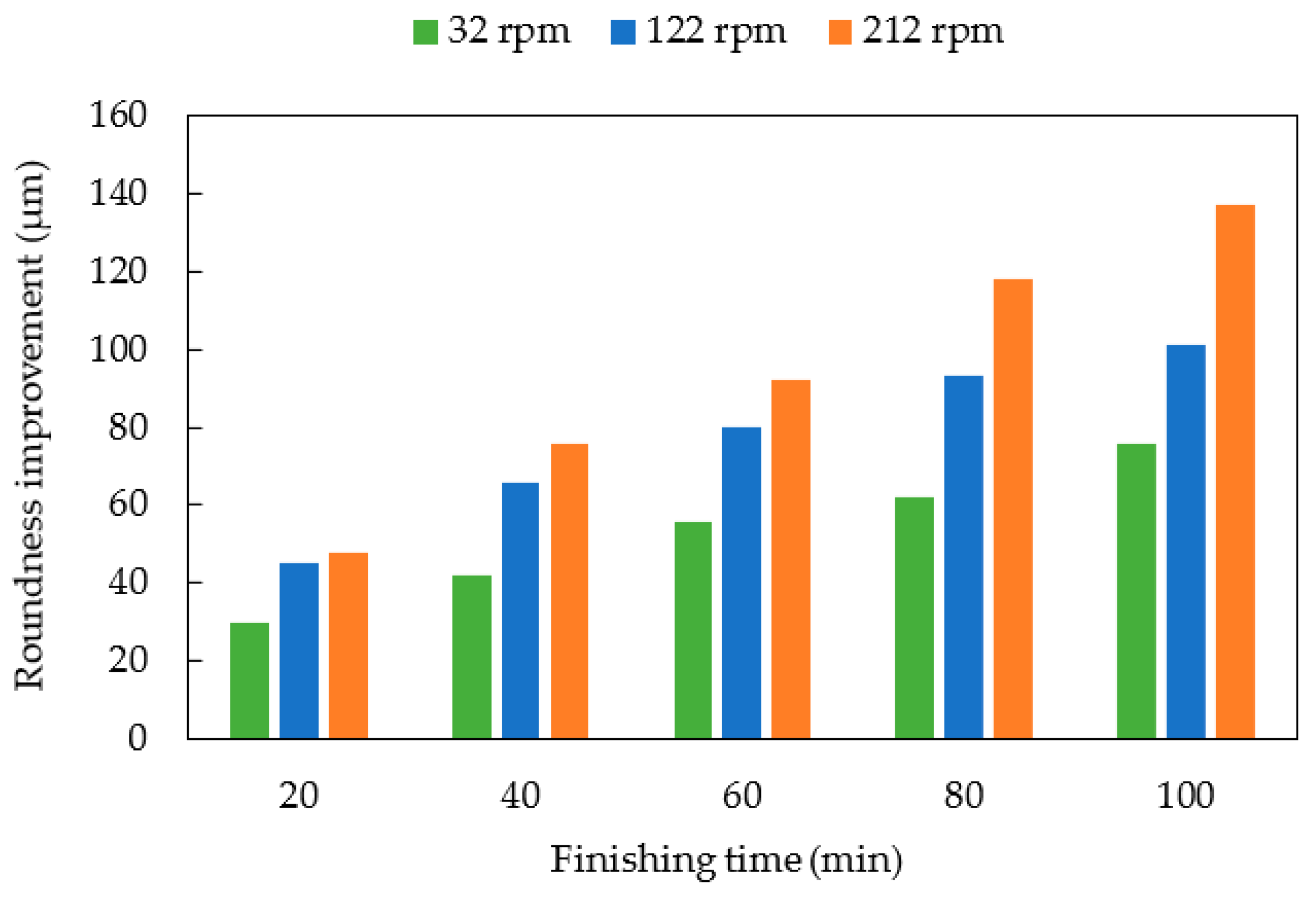
4.1.2. Experimental Results and Discussion

Figure 4 shows the changes in surface roughness and material removal with the finishing time. It can be seen that because the diameter of the magnetic particles and the abrasive particles used in the experiments are the same, the final surface roughness after finishing is almost the same. Additionally, as the rotational speed of the magnetic machining tool increases, the amount of material removal increases.
Figure 5 shows the roundness improvement with the finishing time. It can be seen that the roundness improvement increases with an increase in the rotational speed of the magnetic machining tool. This is because in this process, the internal surface finishing is realized by using a magnetic machining tool whose surface attracts magnetic particles magnetically. According to the force analysis of the magnetic machining tool, the magnetic machining tool has its own weight and rotates, the finishing force during processing also includes the centrifugal force of the magnetic machining tool. Additionally, as the rotational speed of the magnetic machining tool increases, the finishing force increases, so the faster rotational speed of the magnetic machining tool is beneficial to roundness improvement.
Figure 6 shows the roundness profiles of the internal surface of the tube before and after finishing. For different rotational speeds of the magnetic machining tool, the roundness was improved from 205 μm to 129 μm in the case of 32 rpm, from 211 μm to 110 μm in the case of 122 rpm, and from 202 μm to 65 μm in the case of 212 rpm.

4.2. Rotational Speed of Tube

4.2.1. Experimental Conditions and Method

The experimental conditions are shown in Table 2. The SUS 304 stainless steel tube is used as the tube. In order to study the effect of the rotation speed of the tube, the rotational speed of the magnetic pole unit is the same (122 rpm), while the rotational speed of the tube is 35 rpm, 115 rpm and 195 rpm, respectively. The finishing time is 100 min; to understand the changes in roundness, surface roughness and material removal, each stage finishing time is 20 min.

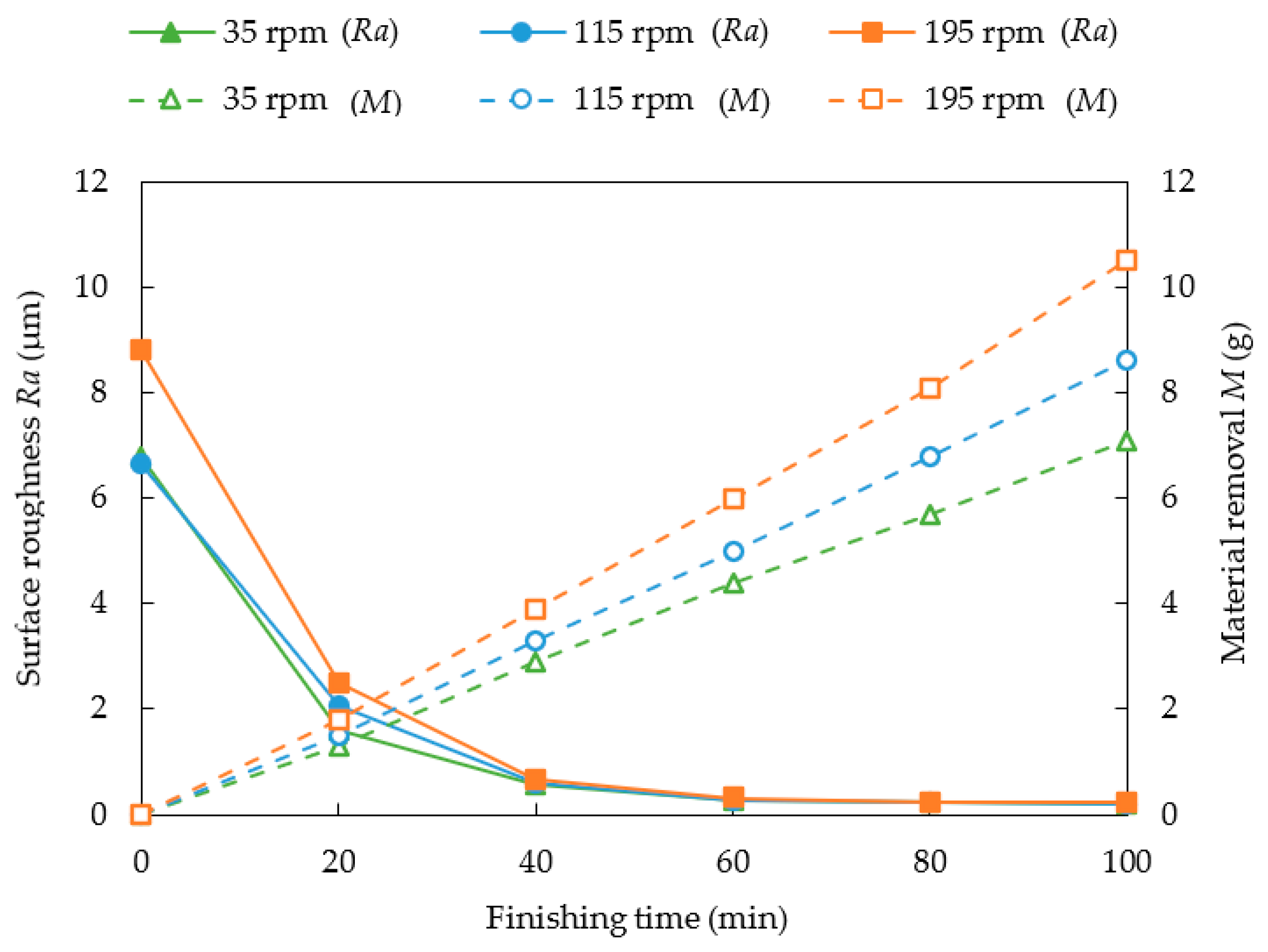
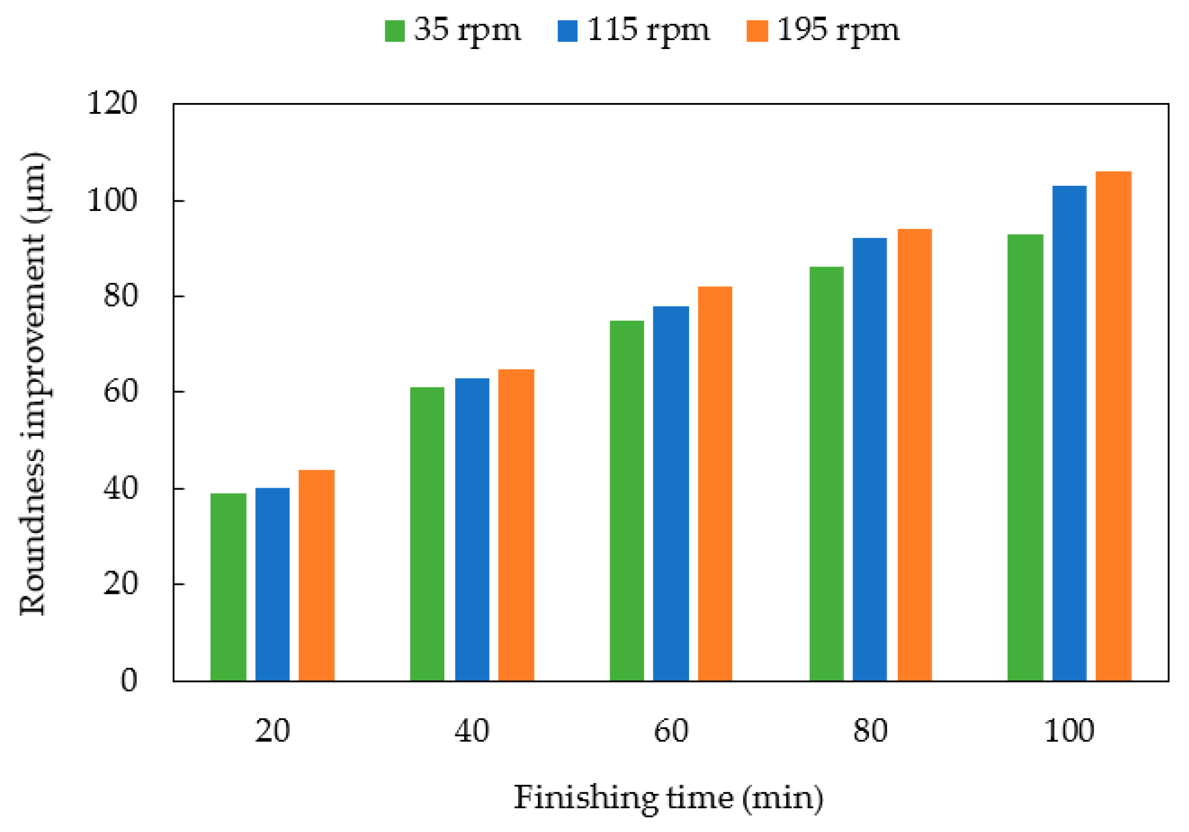
4.2.2. Experimental Results and Discussion

Figure 7 shows the changes in surface roughness and material removal with the finishing time. It can be seen that because the diameter of the magnetic particles and the abrasives used in the experiment are the same, the final surface roughness after finishing is almost the same. Additionally, as the rotational speed of tube increases, the amount of material removal increases.
Figure 8 shows the roundness improvement with the finishing time. It can be seen that the roundness improvement increases with an increase in the rotational speed of the tube. Figure 9 shows the roundness profiles of the internal surface of the tube before and after finishing. For different rotational speeds of the tube, the roundness is improved from 166 μm to 73 μm in the case of 35 rpm, from 166 μm to 63 μm in the case of 115 rpm and from 178 μm to 66 μm in the case of 195 rpm. It can be concluded that with the increase in the rotational speed of the tube, the number of finishing times of tube increases, so the finishing results become better.

5. Influence of Magnetic Particles Distribution on the Magnetic Machining Tool

According to the distribution of the magnetic force lines, the magnetic machining tool is divided into three areas, which are the left area, middle area and right area, as shown in Figure 10.

5.1. Only Distributing Magnetic Particles on One Area

5.1.1. Experimental Conditions and Method

The experimental conditions are shown in Table 3. In this part, the magnetic particles are only placed on the middle area, and the weight of the magnetic particles is 12 g, 13 g and 14 g, respectively. When the thickness of the magnetic particles is 2.382 mm and the same axial length of magnetic particles is 43 mm, the circumferential length of the magnetic particles is 45 mm, 49 mm and 53 mm, respectively. The finishing time is 60 min; to understand the changes in roundness, surface roughness and material removal, each stage finishing time is 10 min.

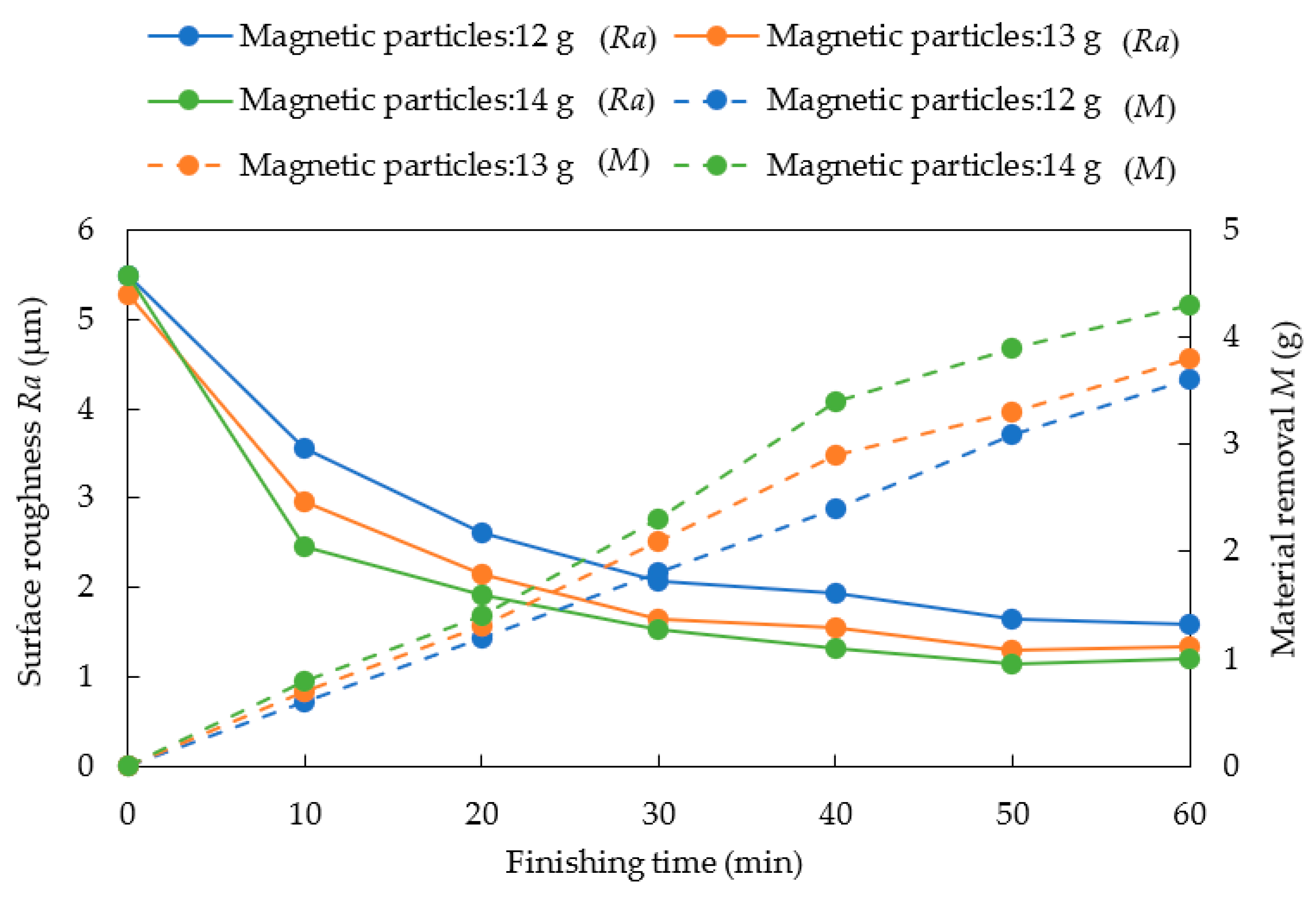
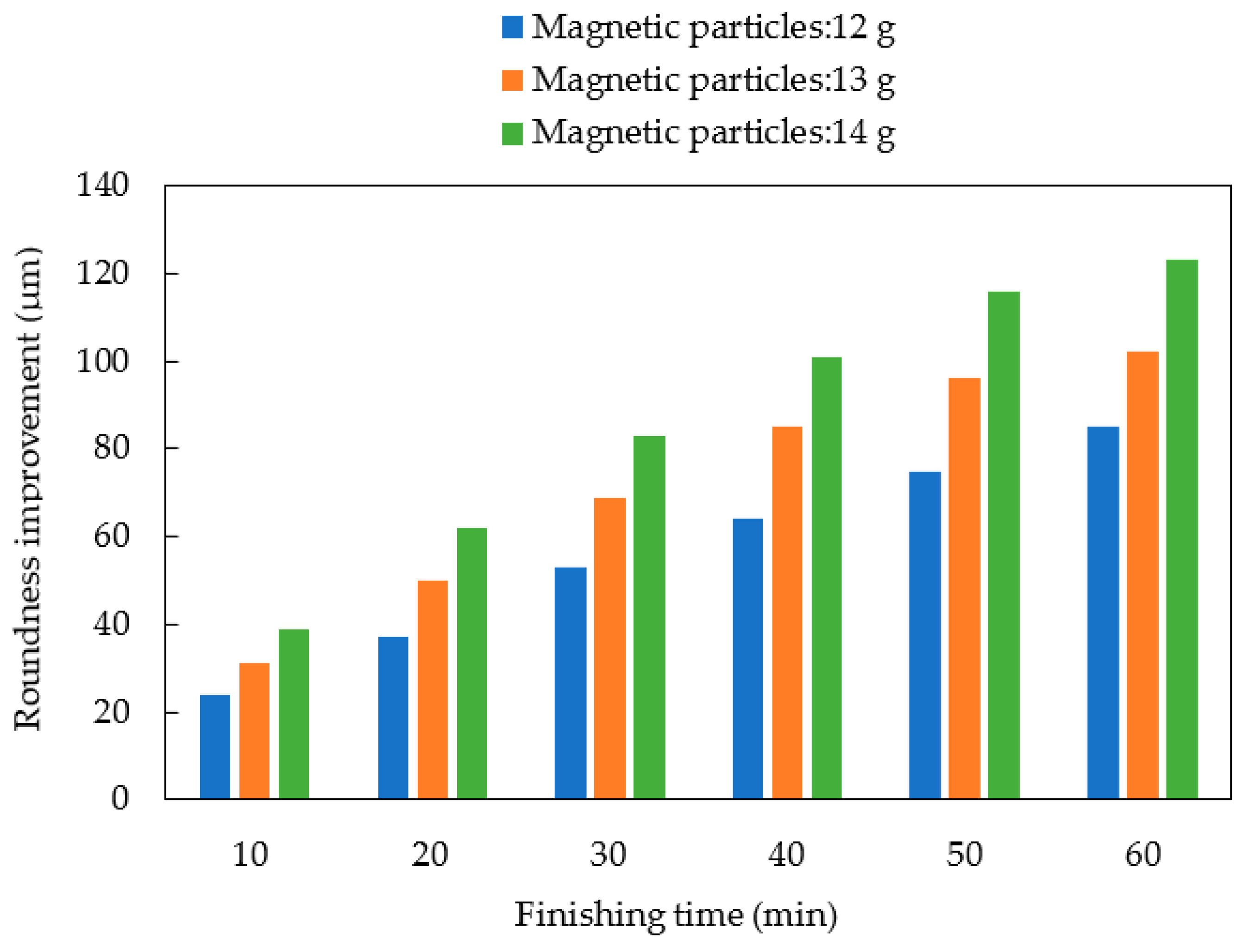
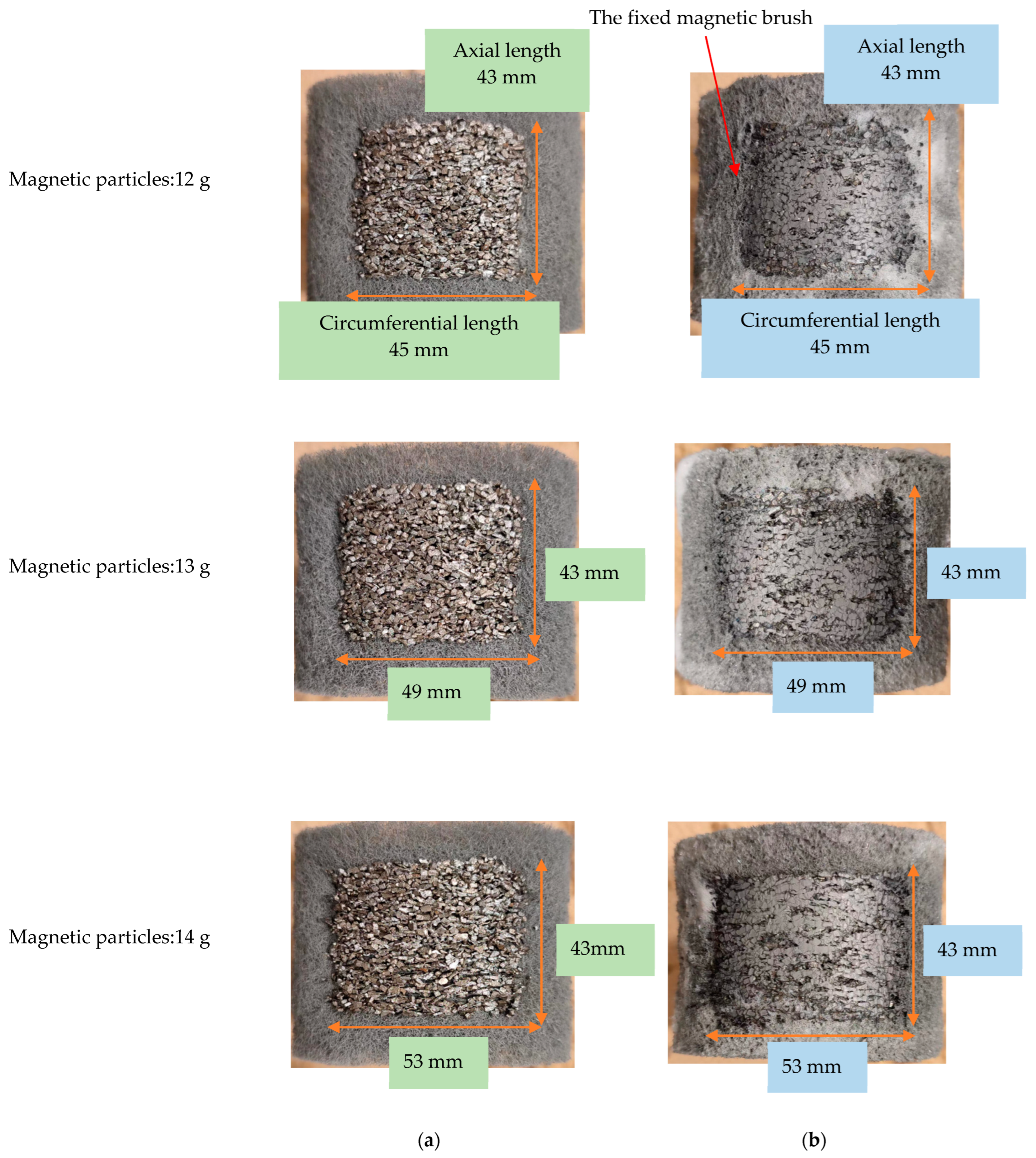
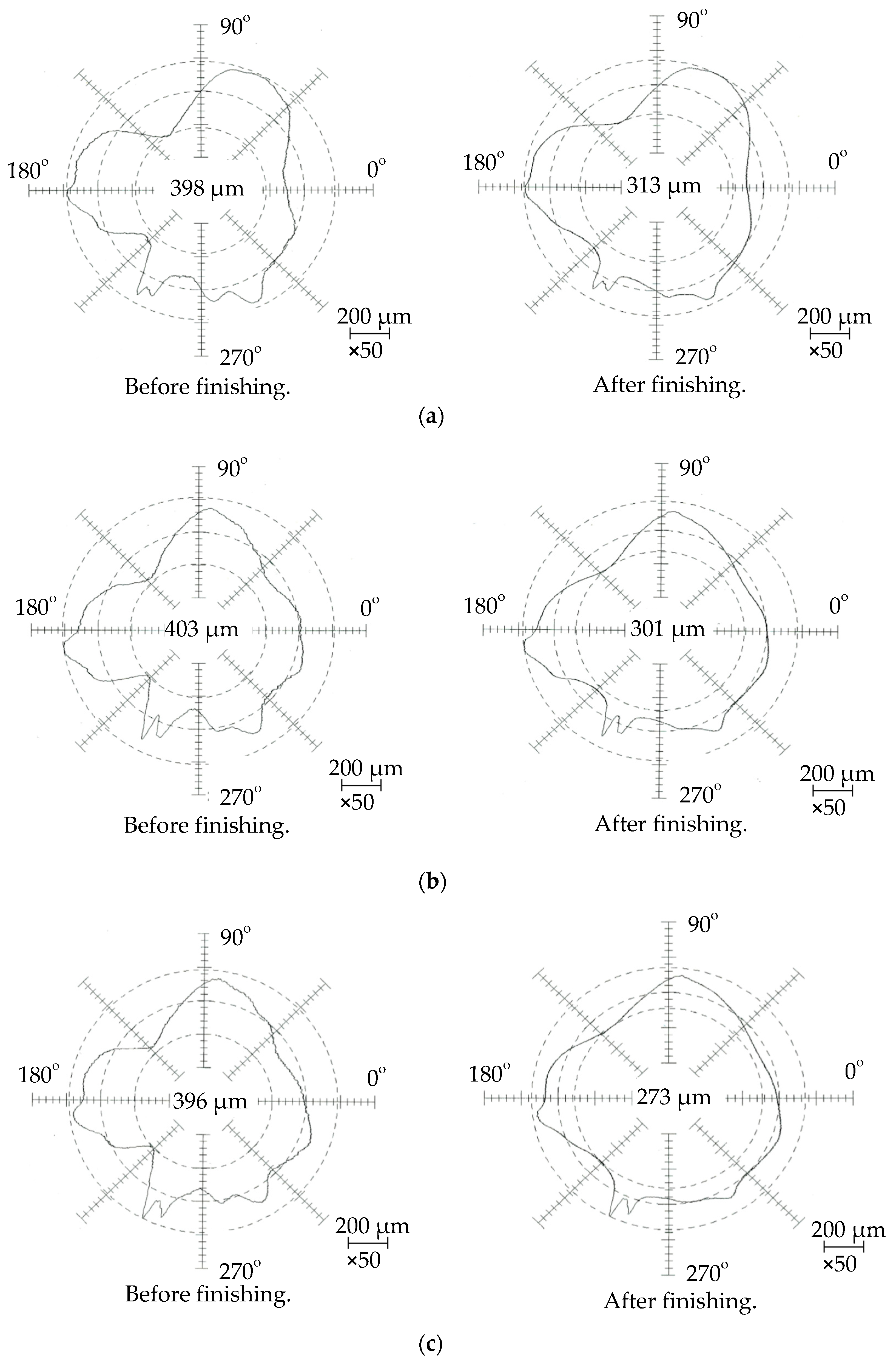
5.1.2. Experimental Results and Discussion

Figure 11 shows the changes in the surface roughness and material removal with the finishing time. It can be seen that the material removal increases and the final roughness decreases with the increase in the weight of the magnetic particles.
Figure 12 shows the changes in roundness with the finishing time. It can be seen that the roundness improvement increases with the increase in the weight of the magnetic particles. When the thickness and axial length of the magnetic particles on the magnetic machining tool are the same, the circumferential length of the magnetic particles becomes longer with the increase in the weight of the magnetic particles. After finishing, due to the magnetic force generated by the magnetic machining tool and the magnetic pole unit exerting pressure on the magnetic particles, a fixed magnetic brush is formed. Figure 13a shows the photographs of the distribution of the magnetic particles on the magnetic machining tool before finishing, the circumferential length of the magnetic particles is 45 mm, 49 mm and 53 mm, respectively. Figure 13b shows the photographs of the magnetic machining tool after finishing. The circumferential length of the fixed magnetic brush is 45 mm, 49 mm and 53 mm, respectively. In the case that the circumference length of the fixed magnetic brush is 45 mm, the roundness improvement value is 85μm after 60 min of finishing. In the case of the circumference length of the fixed magnetic brush being 49 mm, the roundness improvement value is 102 μm. In the case of the circumference length of the fixed magnetic brush being 53 mm, the roundness improvement value is 123 μm. It can be seen that as the circumferential length of the fixed magnetic brush increases, the roundness improvement value also increases.
Figure 14 shows the roundness profiles of the internal surface of the tube before and after finishing. For different rotational speeds of the tube, the roundness is improved from 398 μm to 313 μm in experiment 1, from 403 μm to 301 μm in experiment 2, and from 396 μm to 273 μm in experiment 3.

5.2. Distributing Magnetic Particles on Two Areas and Three Areas

5.2.1. Experimental Conditions and Method

The experimental conditions are shown in Table 4. In this part, the experiments had been carried out; in experiment A, we placed 13 g electrolytic iron particles on the left area and right area, respectively; in experiment B, we placed 12 g electrolytic iron particles on the middle area and 13 g electrolytic iron particles on the right area and in experiment C we placed 12 g electrolytic iron particles on the middle area, 13 g electrolytic iron particles on the left area and the right area, respectively. Furthermore, the thickness of the magnetic particles in each area is 2.382 mm. The finishing time is 60 min; to understand the changes in roundness, surface roughness and material removal, each stage finishing time is 10 min.

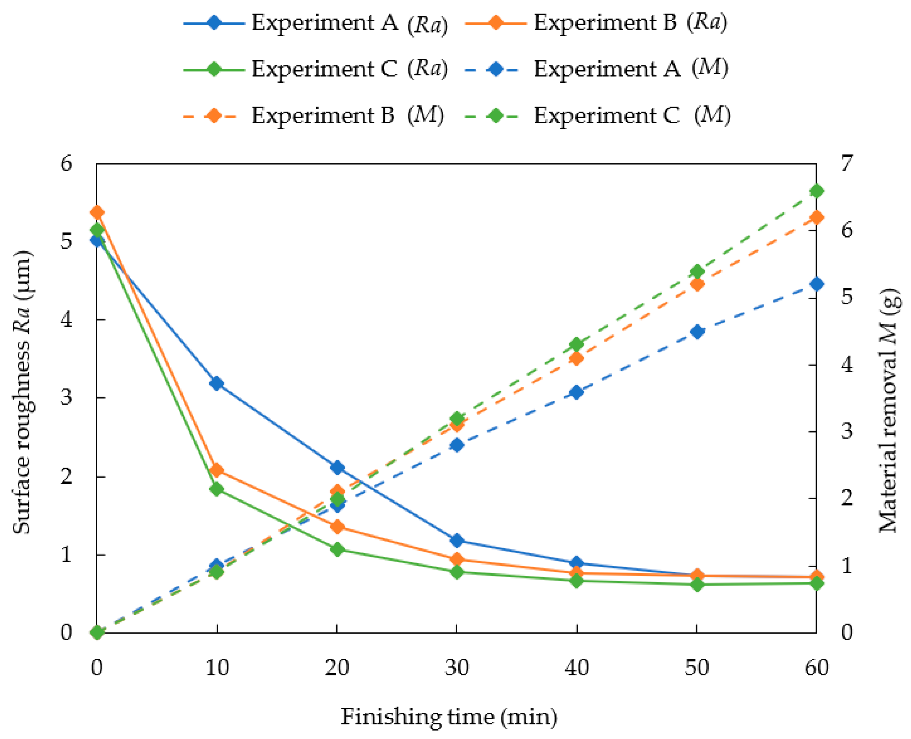
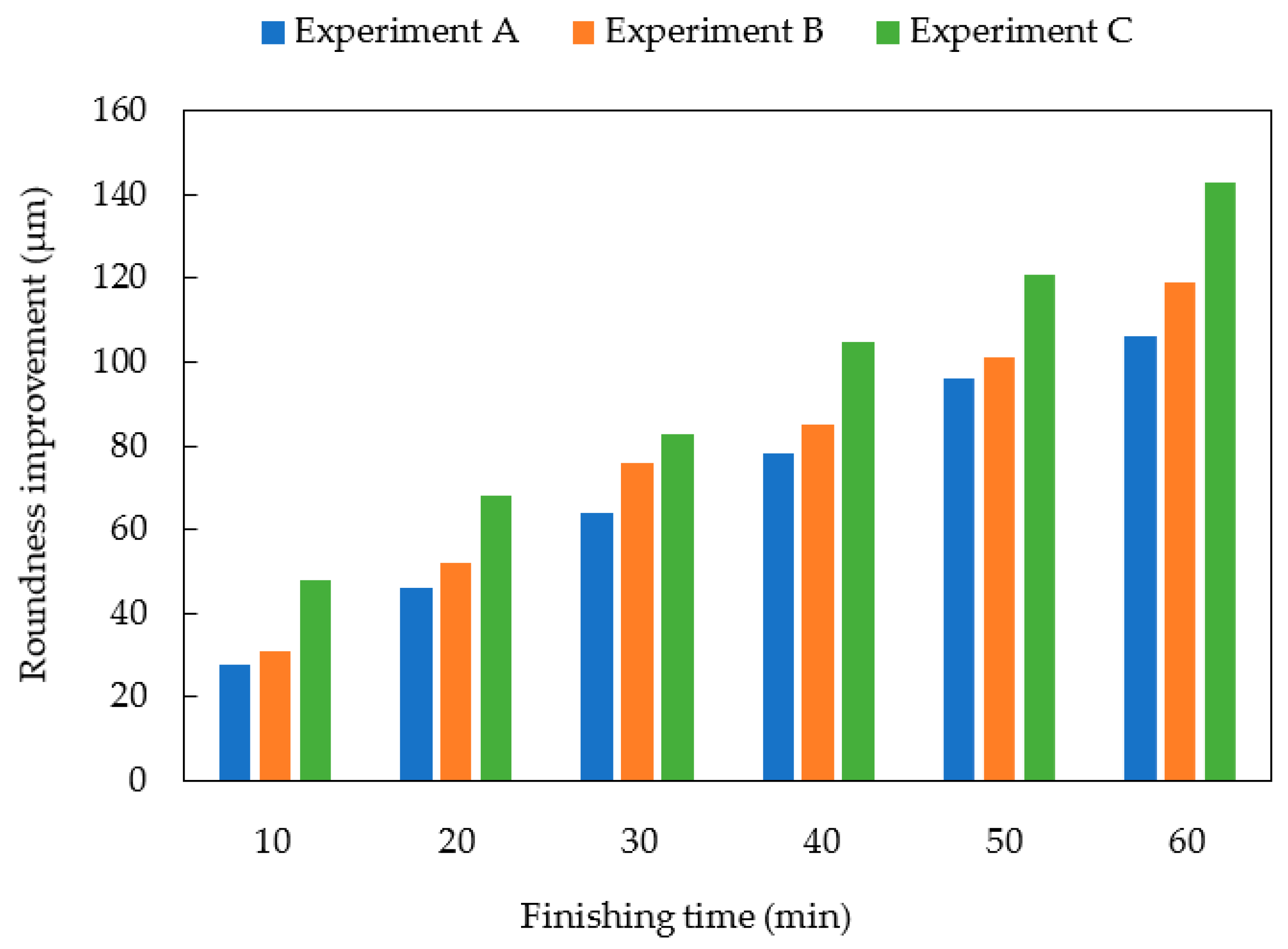
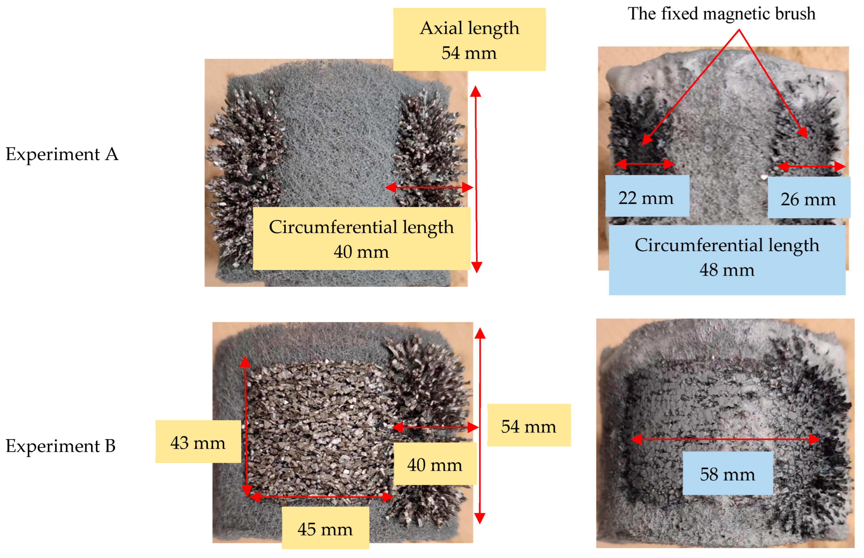
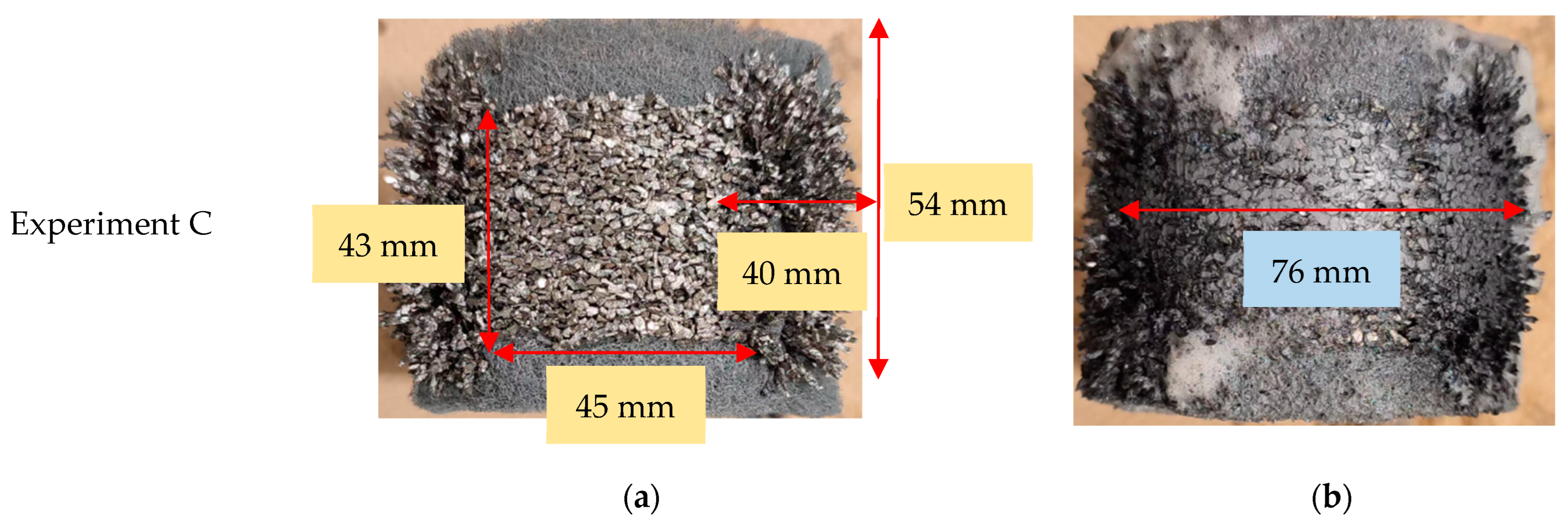
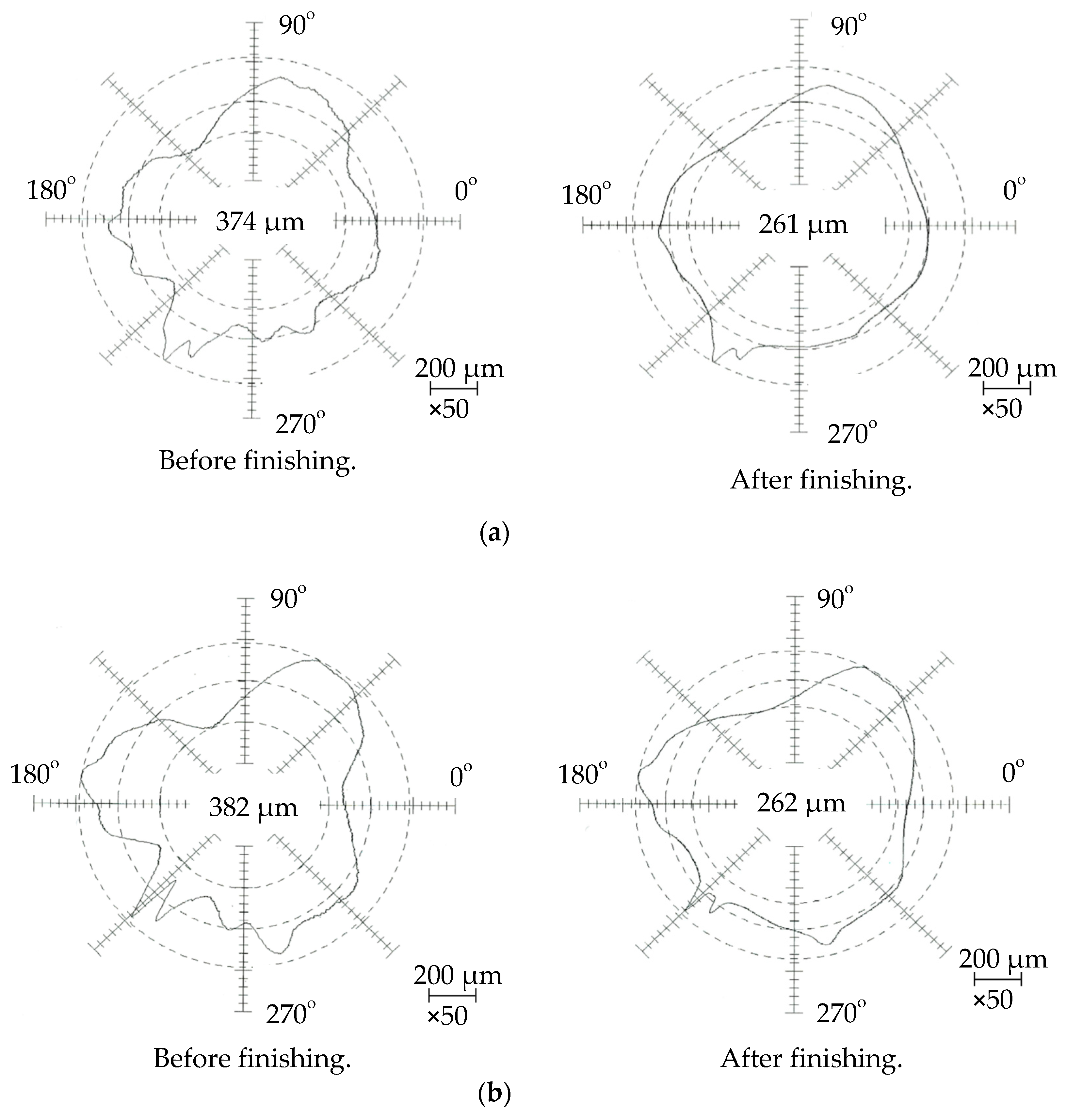
5.2.2. Experimental Results and Discussion

Figure 15 shows the changes in surface roughness and material removal with the finishing time. It can be seen that in experiment C, the final surface roughness after finishing is the best and the amount of material removal is the largest.
Figure 16 shows the changes in roundness with the finishing time. It can be seen that in condition C, the value of roundness improvement is the largest. Figure 17a shows the photographs of the distribution of the magnetic particles on the magnetic machining tool before finishing. Figure 17b shows the photographs of the magnetic machining tool after finishing. The magnetic particles on the left area and right area of the magnetic machining tool form magnetic brushes in the direction of the magnetic force line before finishing. It can be seen that in experiment A, the fixed magnetic brush is discontinuous in the circumferential direction, the circumferential length of the fixed magnetic brush is 22 mm on the left and 26 mm on the right, the total circumferential length is 48 mm; in experiment B, the circumferential length of the fixed magnetic brush is 58 mm and in experiment C, the circumferential length of the fixed magnetic brush is 76 mm. In the case of the circumference length of the fixed magnetic brush being 48 mm, the roundness improvement value is 113 μm after 60 min of finishing. In the case of the circumference length of the fixed magnetic brush being 58 mm, the roundness improvement value is 120 μm. In the case of the circumference length of the fixed magnetic brush being 76 mm, the roundness improvement value is 143 μm. Therefore, it can be concluded that as the circumferential length of the fixed magnetic brush increases, the roundness improvement also increases.
Figure 18 shows the roundness profiles of the internal surface of the tube before and after finishing. The roundness is improved from 374 μm to 261 μm in experiment A, from 382 μm to 262 μm in experiment B, and from 379 μm to 236 μm in experiment C.

5.3. Comprehensive Discussion on the Length of Fixed Magnetic Brush

According to the analysis of the change in the roundness improvement by applying the Fourier series, it is also found that the removal of the peaks of the roundness curve is beneficial to the improvement in the roundness. When the initial roundness curve of the internal surface of the tube has n peaks, the curve wavelength λ is the circumference 2 C/n.
In this process, after finishing, due to the magnetic force generated by the magnetic machining tool and the magnetic pole unit exerting pressure on the magnetic particles, a fixed magnetic brush is formed. In addition, due to the circumference length of the magnetic machining tool is about half of the circumference of the internal surface of the tube that the initial roundness curve of the internal surface of the tube has more than two peaks. As shown in Figure 19a, in the case of the circumferential length of the fixed magnetic brush L being less than the wavelength λ, the number of finishing times (the number of rotations) at the peak point is N.
As shown in Figure 19b, in the case of the circumferential length of the fixed magnetic brush L being greater than the wavelength λ, the number of finishing times for the roundness curve peak is increased.
Then when the circumferential length of the fixed magnetic brush is x λ ≤ L < ( x + 1 2 ) λ, where 1 x C λ , C is the perimeter of internal surface of tube, then the number of finishing times at peak point is 2 x N.
Additionally, when the circumferential length of the fixed magnetic brush is x + 1 2 λ ≤ L < ( x + 1 ) λ, where 1 x C λ , C is the perimeter of internal surface of workpiece, then the number of finishing times at peak point is (2x + 1)N.
Therefore, it can be concluded that when the circumferential length of the fixed magnetic brush is long, the number of times of finishing the peak point increases, so it is beneficial to pursue roundness improvement.

6. Conclusions

This paper investigates the machining mechanism of roundness improvement by the internal magnetic abrasive finishing process using the magnetic machining tool, and the experiments were carried out on the SUS 304 stainless steel tube. The main conclusions are summarized as follows:
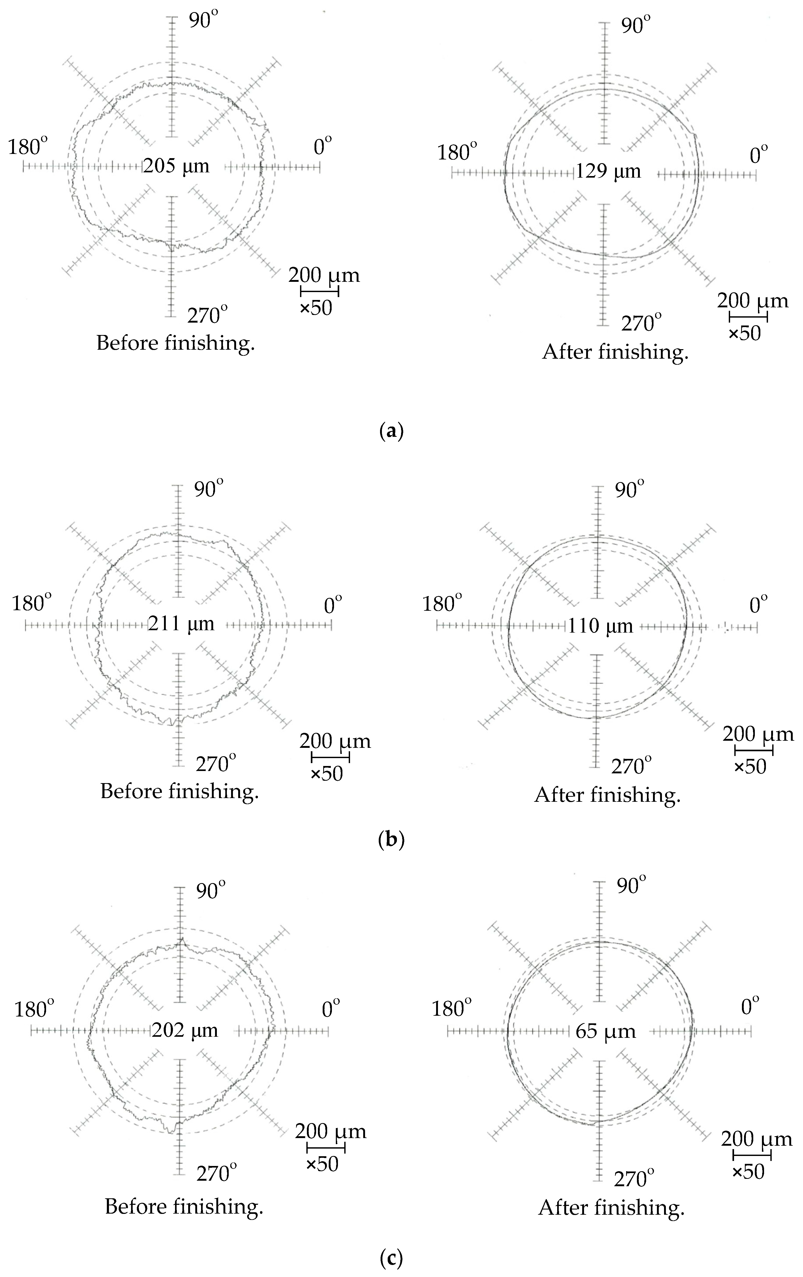
  • Through analyzing the finishing force generated by the magnetic machining tool, it is concluded that the tangential and normal finishing forces increase when the rotational speed of the magnetic machining tool increases, and the resultant finishing force also increases, so the faster rotational speed of the magnetic machining tool is beneficial to roundness improvement. It was obtained that when the rotational speed of the magnetic machining tool was 212 rpm, the roundness was improved from 202 μm to 65 μm.
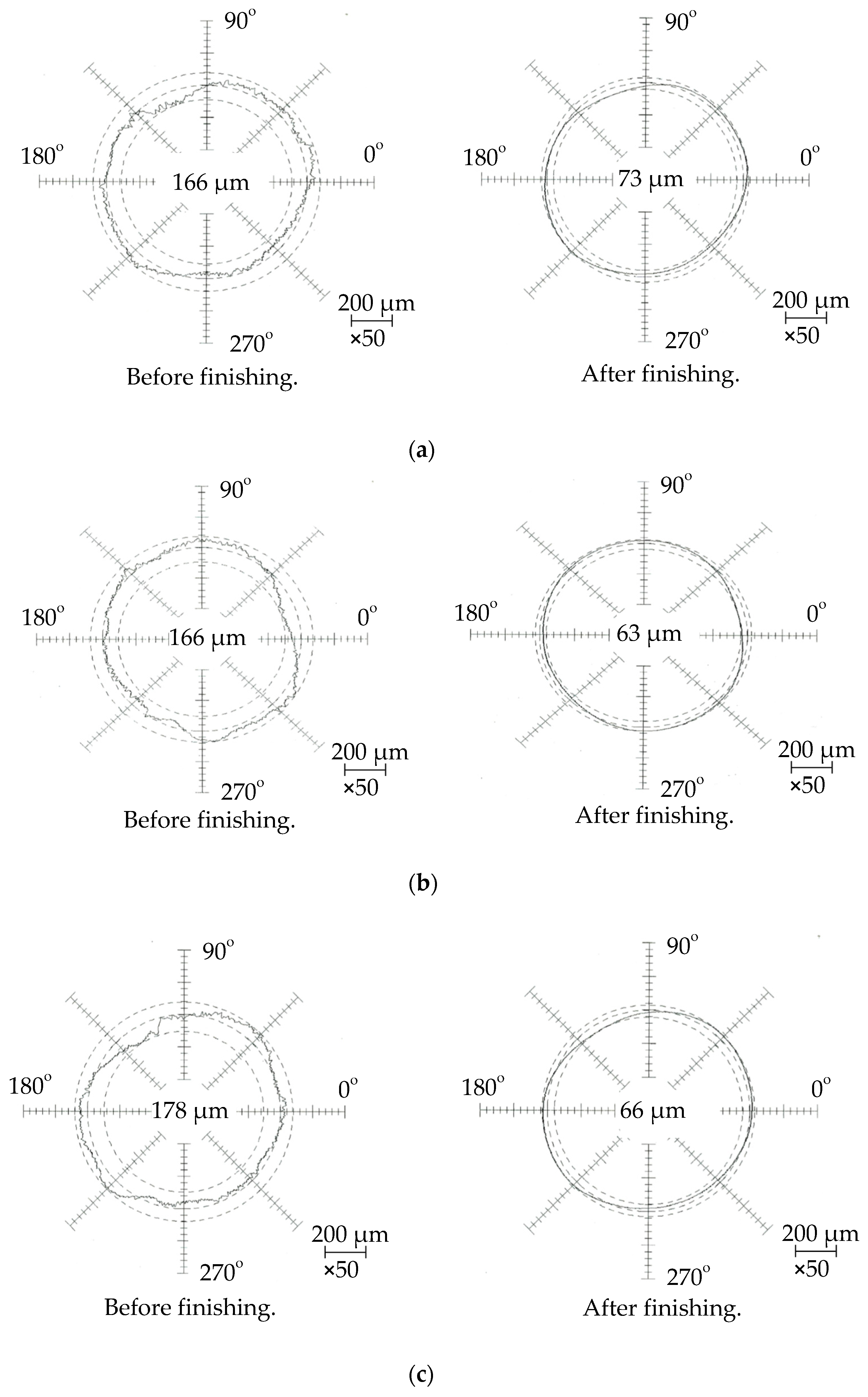
  • Through a discussion on the different rotational speeds of the tube, it can be concluded that the number of finishing times for the tube increases with the increase in the rotational speed of the tube, so the finishing results become better. The experimental results show that the roundness is improved from 178 μm to 66 μm when the rotational speed of the tube is 195 rpm.
  • The roundness improvement was discussed through the different distribution of the magnetic particles on the magnetic machining tool. In this process, due to the magnetic force generated by the magnetic machining tool and the magnetic pole unit exerting pressure on the magnetic particles, a fixed magnetic brush is formed. Therefore, it is concluded that when the distribution of magnetic particles on the magnetic machining tool can form a longer circumferential length for the fixed magnetic brush, it is beneficial to the roundness improvement.

Author Contributions

Conceptualization, J.L. and Y.Z.; data curation, J.L.; formal analysis, J.L.; funding acquisition, Y.Z.; investigation, J.L. and Y.Z.; methodology, J.L. and Y.Z.; project administration, Y.Z.; validation, J.L. and Y.Z.; writing—original draft, J.L. and Y.Z.; writing—review and editing, J.L. and Y.Z. All authors have read and agreed to the published version of the manuscript.

Funding

This research received no external funding.

Data Availability Statement

Not applicable.

Conflicts of Interest

The authors declare no conflict of interest.

References

  1. Shinmura, T.; Takazawa, K.; Hatano, E.; Aizawa, T. Study on magnetic abrasive process (finishing characteristics). Bull. Jpn. Soc. Precis. Eng. 1984, 18, 347–348. [Google Scholar]
  2. Shinmura, T.; Takazawa, K.; Hatano, E.; Matsunaga, M.; Matsuo, T. Study on magnetic abrasive finishing. CIRP Ann. Manuf. Technol. 1990, 39, 325–328. [Google Scholar] [CrossRef]
  3. Singh, D.K.; Jain, V.; Raghuram, V. Experimental investigations into forces acting during a magnetic abrasive finishing process. Int. J. Adv. Manuf. Technol. 2006, 30, 652–662. [Google Scholar] [CrossRef]
  4. Jain, V. Magnetic field assisted abrasive based micro-/nano-finishing. J. Mater. Process. Technol. 2009, 209, 6022–6038. [Google Scholar] [CrossRef]
  5. Bagehorn, S.; Wehr, J.; Maier, H. Application of mechanical surface finishing processes for roughness reduction and fatigue improvement of additively manufactured Ti-6Al-4V parts. Int. J. Fatigue 2017, 102, 135–142. [Google Scholar] [CrossRef]
  6. Souza, A.M.; da Silva, E.J.; Ratay, J.; Yamaguchi, H. Magnetic field-assisted finishing processes: From bibliometric analysis to future trends. J. Braz. Soc. Mech. Sci. Eng. 2022, 44, 327. [Google Scholar] [CrossRef]
  7. Guo, C.S.; Shi, Z.D.; Mullany, B.; Linke, B.; Yamaguchi, H.; Chaudhari, R.; Hucker, S.; Shih, A. Recent advancements in ma-chining with abrasives. J. Manuf. Sci. Eng. 2020, 142, 110810. [Google Scholar] [CrossRef]
  8. Shinmura, T.; Aizawa, T. Study on magnetic abrasive finishing process development of plane finishing apparatus using a stationary type electromagnet. Bull. Jpn. Soc. Precis. Eng. 1989, 23, 236–239. (In Japanese) [Google Scholar]
  9. Shinmura, T.; Takazawa, K.; Hatano, E.; Aizawa, T. Study on magnetic abrasive finishing (2nd report) finishing characteristics. J. Jpn. Soc. Precis. Eng. 1986, 52, 1761–1767. (In Japanese) [Google Scholar] [CrossRef]
  10. Shinmura, T.; Aizawa, T. Development of plane magnetic abrasive finishing apparatus and its finishing performance. (2nd report). Finishing apparatus using a stationary type electromagnet. J. Jpn. Soc. Precis. Eng. 1988, 54, 928–933. [Google Scholar] [CrossRef]
  11. Zou, Y.; Xie, H.; Dong, C.; Wu, J. Study on complex micro surface finishing of alumina ceramic by the magnetic abrasive finishing process using alternating magnetic field. Int. J. Adv. Manuf. Technol. 2018, 97, 2193–2202. [Google Scholar] [CrossRef]
  12. Xie, H.; Zou, Y.; Dong, C.; Wu, J. Study on the magnetic abrasive finishing process using alternating magnetic field: Investigation of mechanism and applied to aluminum alloy plate. Int. J. Adv. Manuf. Technol. 2019, 102, 1509–1520. [Google Scholar] [CrossRef]
  13. Zou, Y.; Xie, H.; Zhang, Y. Study on surface quality improvement of the plane magnetic abrasive finishing process. Int. J. Adv. Manuf. Technol. 2020, 109, 1825–1839. [Google Scholar] [CrossRef]
  14. Xu, J.; Zou, Y. Development of a new magnetic abrasive finishing process with renewable abrasive particles using the circulatory system. Precis. Eng. 2021, 72, 417–425. [Google Scholar] [CrossRef]
  15. Xu, J.Y.; Zou, Y.H.; Xie, H.J. Investigation on the finishing characteristics of a magnetic abrasive finishing process with mag-netic abrasive slurry circulation system. Machines 2021, 9, 195. [Google Scholar] [CrossRef]
  16. Yamaguchi, H.; Shinmura, T.; Kobayashi, A. Development of an internal magnetic abrasive finishing process for nonferro-magnetic complex shaped tubes. JSME Int. J. Ser. C 2001, 44, 275–281. [Google Scholar] [CrossRef]
  17. Kang, J.; Yamaguchi, H. Internal finishing of capillary tubes by magnetic abrasive finishing using a multiple pole-tip system. Precis. Eng. 2012, 36, 510–516. [Google Scholar] [CrossRef]
  18. Kang, J.; George, A.; Yamaguchi, H. High-speed Internal Finishing of Capillary Tubes by Magnetic Abrasive Finishing. Procedia CIRP 2012, 1, 414–418. [Google Scholar] [CrossRef]
  19. Yin, S.H.; Shinmura, T. A comparative study: Polishing characteristics and its mechanisms of three vibration modes in vibra-tion-assisted magnetic abrasive polishing. Int. J. Mach. Tool. Manuf. 2012, 44, 383–390. [Google Scholar] [CrossRef]
  20. Yin, S.; Shinmura, T. Vertical vibration-assisted magnetic abrasive finishing and deburring for magnesium alloy. Int. J. Mach. Tools Manuf. 2004, 44, 1297–1303. [Google Scholar] [CrossRef]
  21. Kim, J.-D. Polishing of Ultra-clean Inner Surfaces Using Magnetic Force. Int. J. Adv. Manuf. Technol. 2003, 21, 91–97. [Google Scholar] [CrossRef]
  22. Jha, S.; Jain, V. Design and development of the magnetorheological abrasive flow finishing (MRAFF) process. Int. J. Mach. Tools Manuf. 2004, 44, 1019–1029. [Google Scholar] [CrossRef]
  23. Jha, S.; Jain, V.K.; Komanduri, R. Effect of extrusion pressure and number of finishing cycles on surface roughness in mag-netorheological abrasive flow finishing (MRAFF) process. Int. J. Adv. Manuf. Technol. 2007, 33, 725–729. [Google Scholar] [CrossRef]
  24. Das, M.; Jain, V.K.; Ghoshdastidar, P.S. Analysis of magnetorheological abrasive flow finishing (MRAFF) process. Int. J. Adv. Manuf. Technol. 2007, 38, 613–621. [Google Scholar] [CrossRef]
  25. Zou, Y.H.; Shinmura, T. A Study on the Magnetic Field Assisted Machining Process for Internal Finishing Using a Magnetic Machining Jig. Key Eng. Mater. 2004, 257–258, 505–510. [Google Scholar] [CrossRef]
  26. Muhamad, M.R.; Zou, Y.H.; Sugiyama, H. Development of a new internal finishing of tube by magnetic abrasive finishing process combined with electrochemical machining. Int. J. Mech. Eng. Appl. 2015, 3, 22–29. [Google Scholar]
  27. Chen, K.-Y.; Tu, T.-Y.; Fan, Y.-H.; Wang, A.-C.; Fu, P.-K. Study on the Polishing Characteristics of the Rotating Cylinder-Based Magnetic Gel Abrasive Finishing. Processes 2021, 9, 1794. [Google Scholar] [CrossRef]
  28. Cheng, K.-C.; Chen, K.-Y.; Tsui, H.-P.; Wang, A.-C. Characteristics of the Polishing Effects for the Stainless Tubes in Magnetic Finishing with Gel Abrasive. Processes 2021, 9, 1561. [Google Scholar] [CrossRef]
  29. Cheng, K.-C.; Wang, A.-C.; Chen, K.-Y.; Huang, C.-Y. Study of the Polishing Characteristics by Abrasive Flow Machining with a Rotating Device. Processes 2022, 10, 1362. [Google Scholar] [CrossRef]
  30. Liu, J.N.; Zou, Y.H. Study on mechanism of roundness improvement by the internal magnetic abrasive finishing process using magnetic machining tool. Machines 2021, 9, 195. [Google Scholar] [CrossRef]
  31. Liu, J.N.; Zou, Y.H. Discussion on Roundness of Non-Ferromagnetic Tube by Interior Magnetic Abrasive Finishing Using a Magnetic Machining Jig. Mater. Sci. Forum 2021, 1018, 105–110. [Google Scholar] [CrossRef]
Figure 1. (a) Schematic of the internal magnetic abrasive finishing process using magnetic machining tool; (b) Force analysis model diagram of the magnetic machining tool.
Jmmp 07 00049 g001aJmmp 07 00049 g001b
Figure 2. Straight-line expansion of the internal surface of the tube along the circumference direction.
Jmmp 07 00049 g002
Figure 3. External view of the experimental setup.
Jmmp 07 00049 g003
Figure 4. Changes in material removal and surface roughness with finishing time.
Jmmp 07 00049 g004
Figure 5. Roundness improvement with finishing time.
Jmmp 07 00049 g005
Figure 6. Roundness profiles of the internal surface of the tube before and after finishing. (a) 32 rpm; (b) 122 rpm; (c) 212 rpm.
Jmmp 07 00049 g006
Figure 7. Changes in material removal and surface roughness with finishing time.
Jmmp 07 00049 g007
Figure 8. Roundness improvement with finishing time.
Jmmp 07 00049 g008
Figure 9. Roundness profiles of the internal surface of the tube before and after finishing. (a) 35 rpm; (b) 115 rpm; (c) 195 rpm.
Jmmp 07 00049 g009
Figure 10. Distribution of magnetic force lines of magnetic machining tool.
Jmmp 07 00049 g010
Figure 11. Changes in material removal and surface roughness with finishing time.
Jmmp 07 00049 g011
Figure 12. Roundness improvement with finishing time.
Jmmp 07 00049 g012
Figure 13. Photographs of magnetic machining tool before and after finishing. (a) Before finishing; (b) After finishing.
Jmmp 07 00049 g013
Figure 14. Roundness profiles of the internal surface of the tube before and after finishing. (a) Magnetic particles:12 g; (b) Magnetic particles:13 g; (c) Magnetic particles:14 g.
Jmmp 07 00049 g014
Figure 15. Changes in material removal and surface roughness with finishing time.
Jmmp 07 00049 g015
Figure 16. Roundness improvement with finishing time.
Jmmp 07 00049 g016
Figure 17. Photographs of magnetic machining tool before and after finishing. (a) Before finishing; (b) After finishing.
Jmmp 07 00049 g017aJmmp 07 00049 g017b
Figure 18. Roundness profiles of the internal surface of the tube before and after finishing. (a) Experiment A; (b) Experiment B; (c) Experiment C.
Jmmp 07 00049 g018aJmmp 07 00049 g018b
Figure 19. Diagram of the relationship between the circumferential length of fixed magnetic brush and the wavelength of roundness curve. (a) L < λ; (b) L ≥ λ.
Jmmp 07 00049 g019
Table 1. Experimental conditions.
WorkpieceSUS304 stainless steel tube Ø89.1 × 79.1 × 200 mm
Clearance: 7 mm (Thickness of tube is equivalent to 10 mm)
Rotational speed: 66 rpm
Magnetic machining toolMagnet: Nd-Fe-B permanent magnet
Yoke: SS400 steel
Molding material: Polymer
Magnetic pole unitMagnet: Ferrite permanent magnet 50 × 35 × 26 mm
Yoke: SS400 steel
Rotational speed: 32 rpm
           122 rpm
           212 rpm
Reciprocating speed: 1500 mm/min
Magnetic particlesElectrolytic iron particles: 1680 µm in mean dia., 24 g
Abrasive particlesWA #400, 2.5 g
Grinding fluidWater-soluble grinding fluid (SCP-23): 30 g
Finishing width80 mm
Finishing time 100 min (each stage 20 min)
Table 2. Experimental conditions.
WorkpieceSUS304 stainless steel tube Ø89.1 × 79.1 × 200 mm
Clearance: 7 mm (Thickness of tube is equivalent to 10 mm.)
Rotational speed: 35 rpm
           115 rpm
           195 rpm
Magnetic machining toolMagnet: Nd-Fe-B permanent magnet
Yoke: SS400 steel
Molding material: Polymer
Magnetic pole unitMagnet: Ferrite permanent magnet 50 × 35 × 26 mm
Yoke: SS400 steel
Rotational speed: 122 rpm
Reciprocating speed: 1500 mm/min
Magnetic particlesElectrolytic iron particles: 1680 µm in mean dia., 24 g
Abrasive particlesWA #400, 2.5 g
Grinding fluidWater-soluble grinding fluid (SCP-23): 30 g
Finishing width80 mm
Finishing time 100 min (each stage 20 min)
Table 3. Experimental condition.
WorkpieceSUS304 stainless steel tube Ø89.1 × 79.1 × 200 mm
Clearance: 7 mm (Thickness of tube is equivalent to 10 mm)
Rotational speed: 80 rpm
Magnetic machining toolMagnet: Nd-Fe-B permanent magnet
Yoke: SS400 steel
Molding material: Polymer
Magnetic pole unitMagnet: Ferrite permanent magnet 50 × 35 × 26 mm
Yoke: SS400 steel
Rotational speed: 150 rpm
Reciprocating speed: 1500 mm/min
Magnetic particlesElectrolytic iron particles: 1680 µm in mean dia.
Only placing magnetic particles on the middle area
Experiment 1: 12 g; Experiment 2: 13 g; Experiment 3: 14 g
Jmmp 07 00049 i001
Abrasive particlesWA #400, 2.5 g
Grinding fluidWater-soluble grinding fluid (SCP-23): 30 g
Finishing width80 mm
Finishing time 60 min (each stage 10 min)
Table 4. Experimental conditions.
WorkpieceSUS304 stainless steel tube Ø89.1 × 79.1 × 200 mm
Clearance: 7 mm (Thickness of tube is equivalent to 10 mm)
Rotational speed: 80 rpm
Magnetic machining toolMagnet: Nd-Fe-B permanent magnet, Yoke: SS400 steel
Molding material: Polymer
Magnetic pole unitMagnet: Ferrite permanent magnet 50 × 35 × 26 mm,
Yoke: SS400 steel, Rotational speed: 150 rpm
Reciprocating speed: 1500 mm/min
Magnetic particlesElectrolytic iron particles: 1680 µm in mean dia.
Experiment A: On the left and right areas 13 × 2 g
Jmmp 07 00049 i002
Experiment B: On the middle area 12 g and on the right area 13 g
Jmmp 07 00049 i003
Experiment C: On the middle area 12 g, on the left and right areas 13 × 2 g
Jmmp 07 00049 i004
Abrasive particlesWA #400, 2.5 g
Grinding fluidWater-soluble grinding fluid (SCP-23): 30 g
Finishing width80 mm
Finishing time 60 min (each stage 10 min)
Disclaimer/Publisher’s Note: The statements, opinions and data contained in all publications are solely those of the individual author(s) and contributor(s) and not of MDPI and/or the editor(s). MDPI and/or the editor(s) disclaim responsibility for any injury to people or property resulting from any ideas, methods, instructions or products referred to in the content.

