
Fundamental Investigations to Evaluate the Influence of Notching Processes on a Subsequent Cyclic Bending Process for the Production of Wire Cores
Abstract
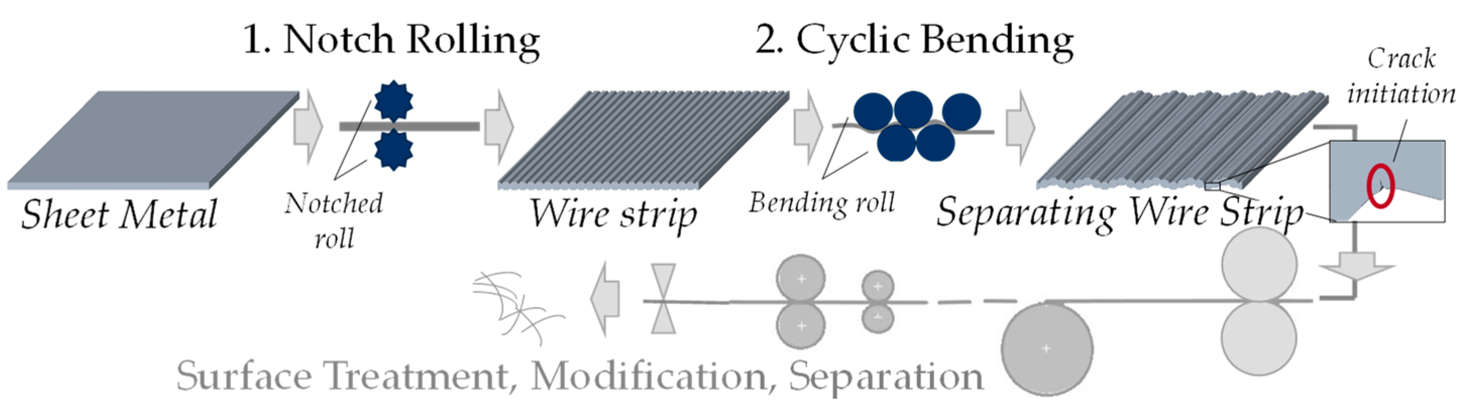
:1. Introduction
2. Materials and Methods
2.1. Sheet Metal
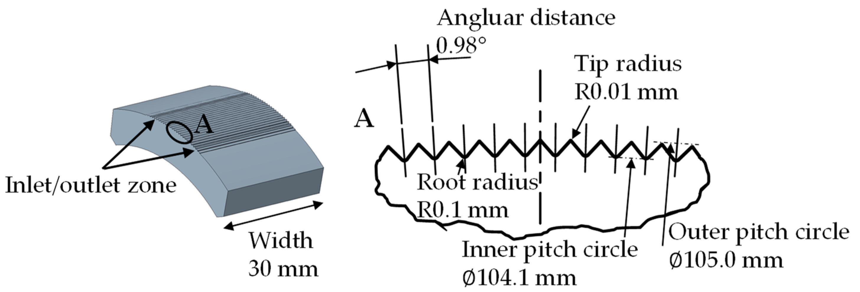
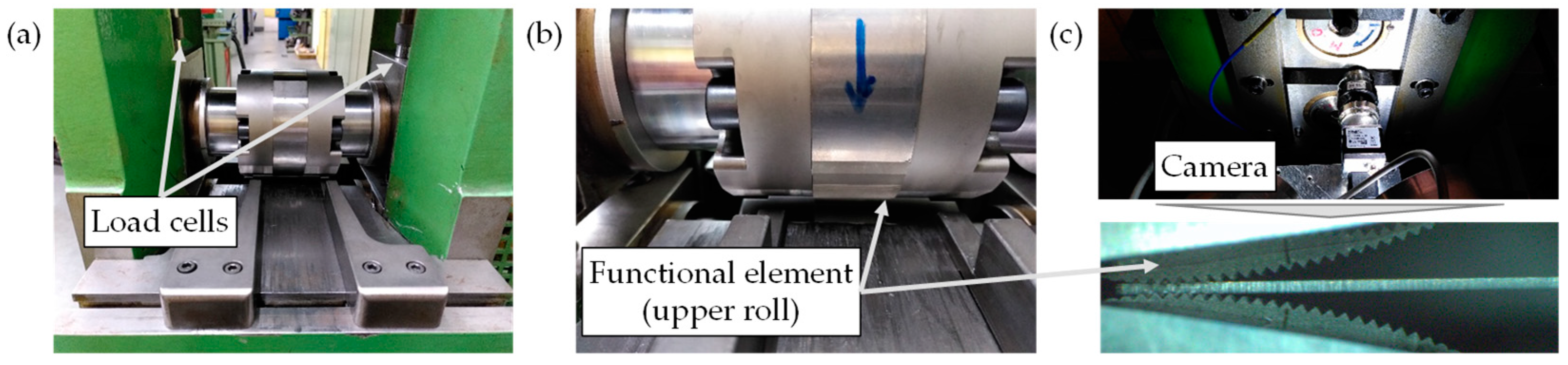
2.2. Experimental Setup and Design
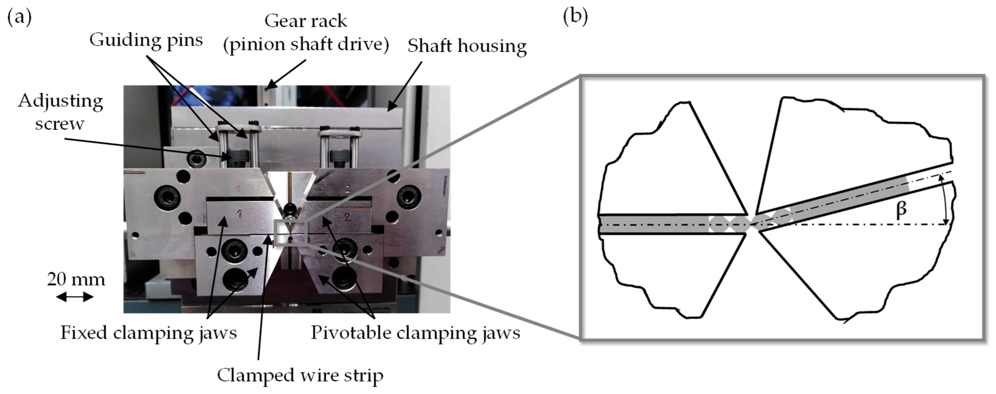
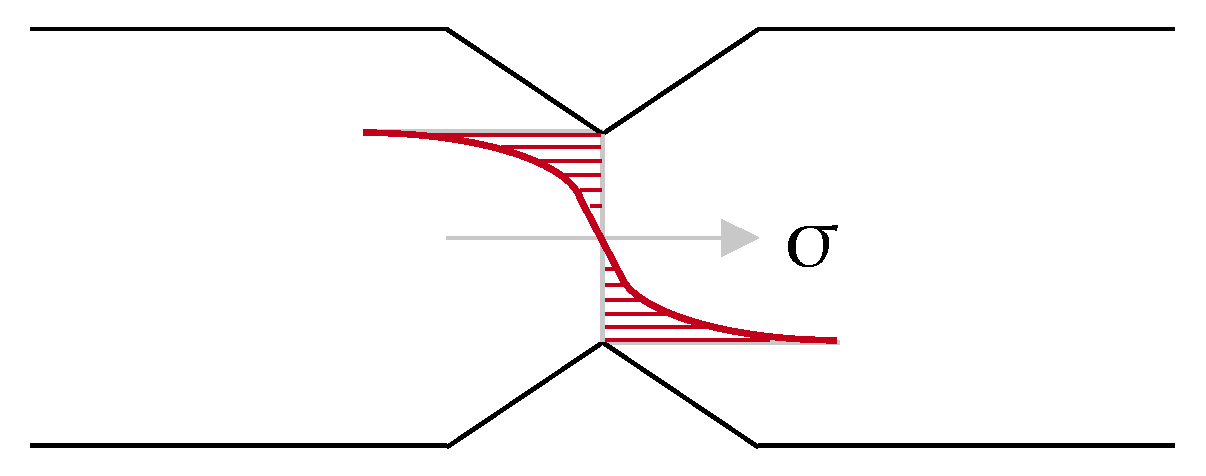
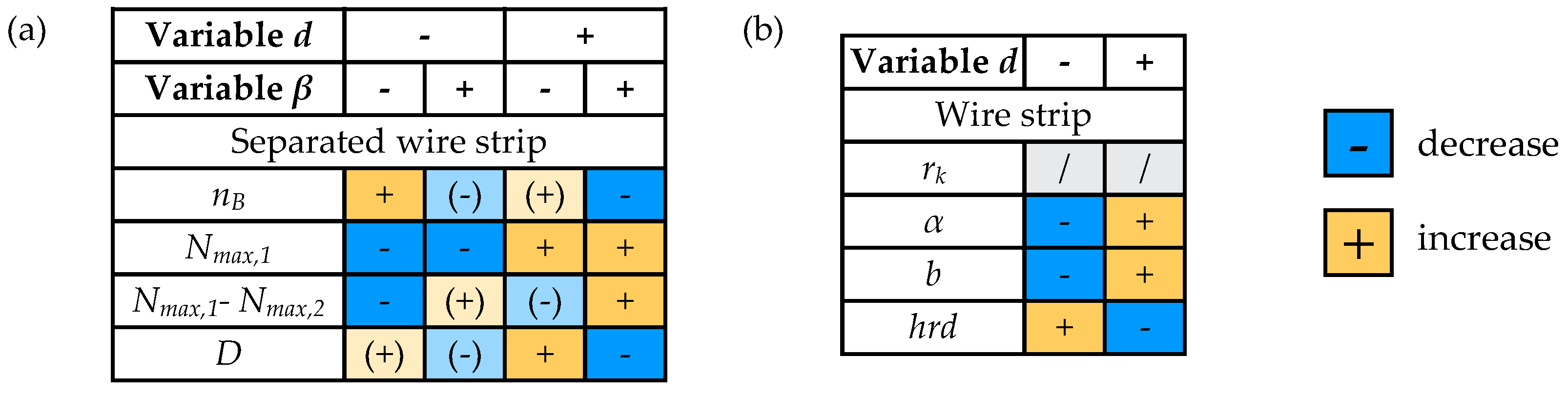
2.2.1. Interaction Study of Notch Rolling and Cyclic Bending
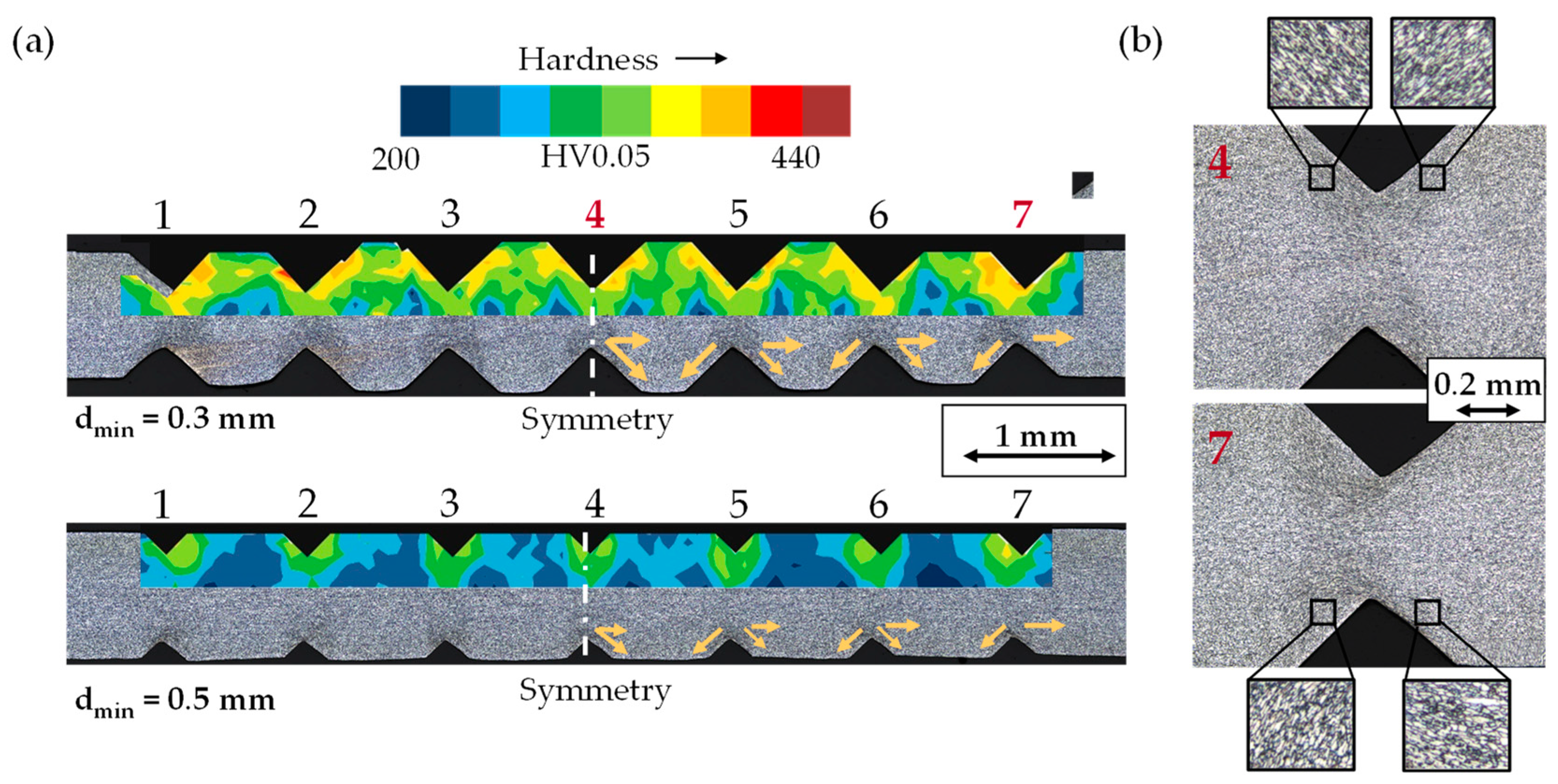
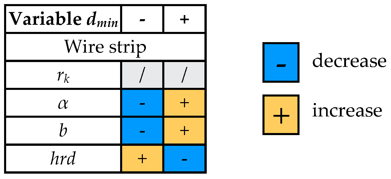
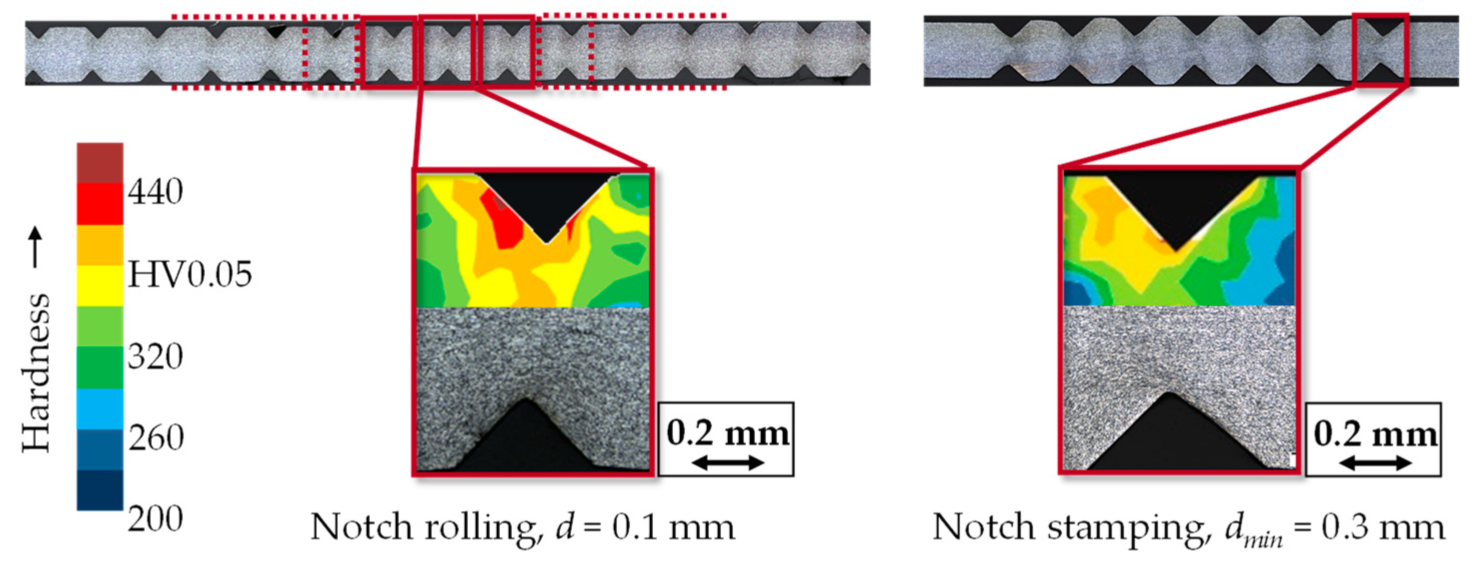
2.2.2. Comparison Study of Notch Rolling and Notch Stamping
- dmin = 0.3 mm and
- dmin = 0.5 mm.
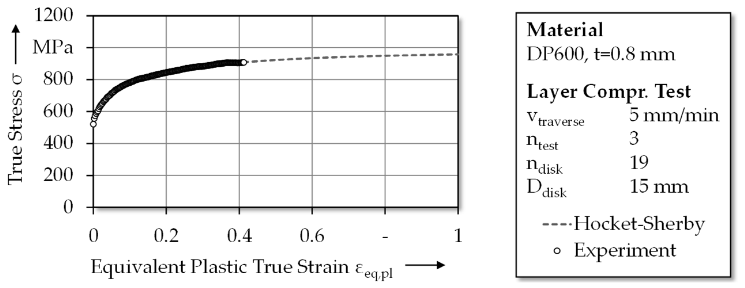
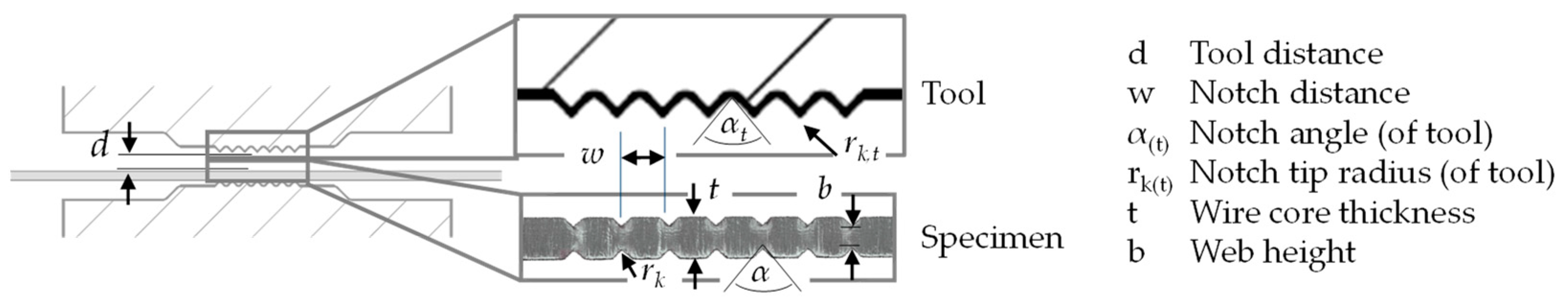
2.3. Evaluation Methods
3. Results
3.1. Characteristics of Notch Rolling and Cyclic Bending (Interaction Study)
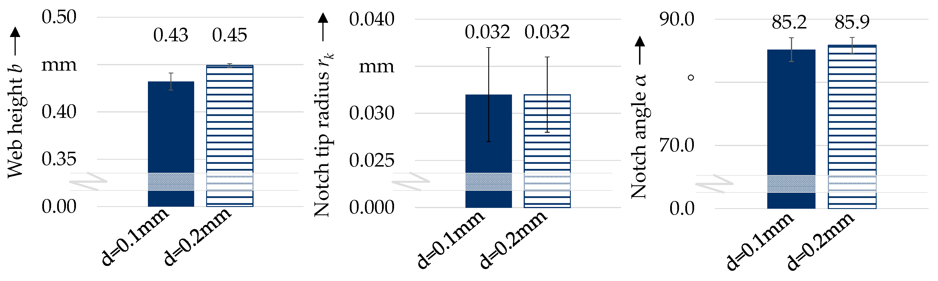
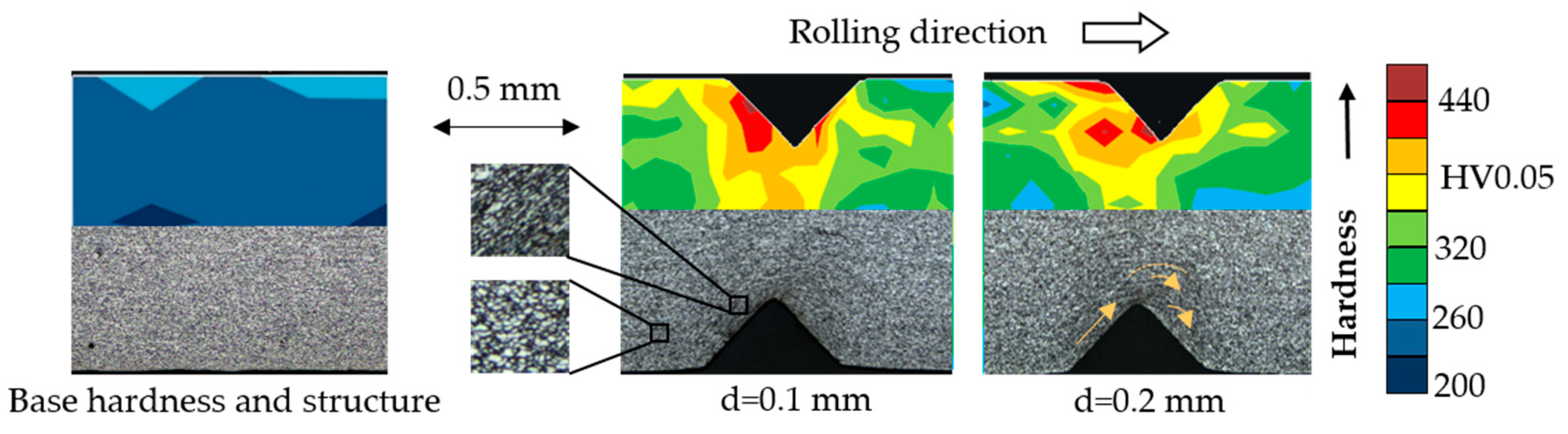
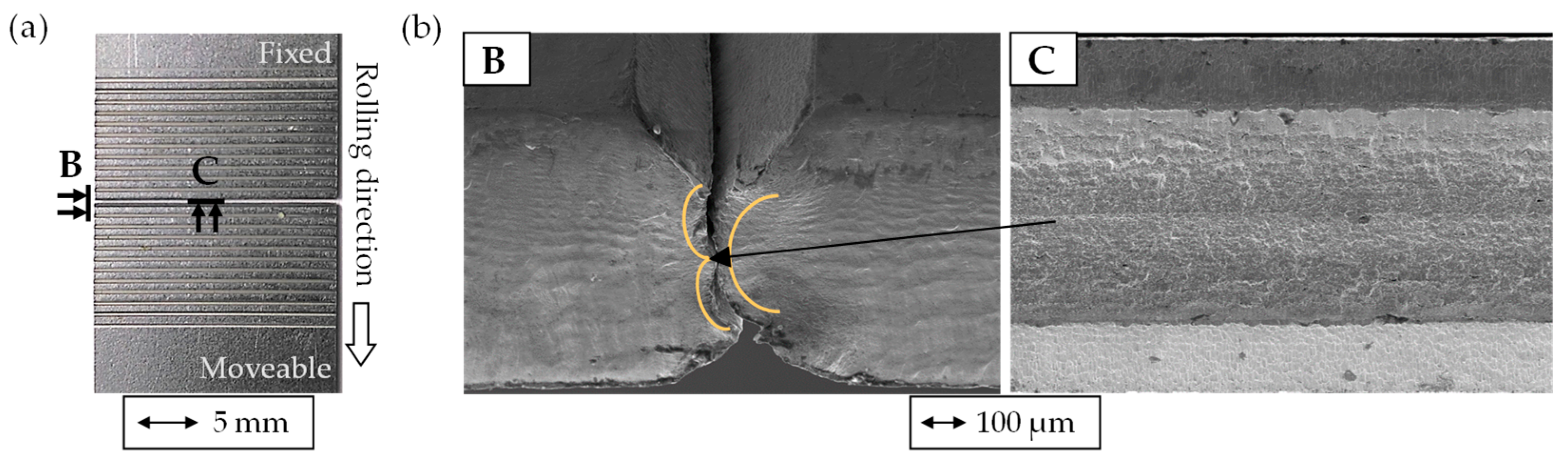
3.1.1. Characteristics of Rolled Wire Strip
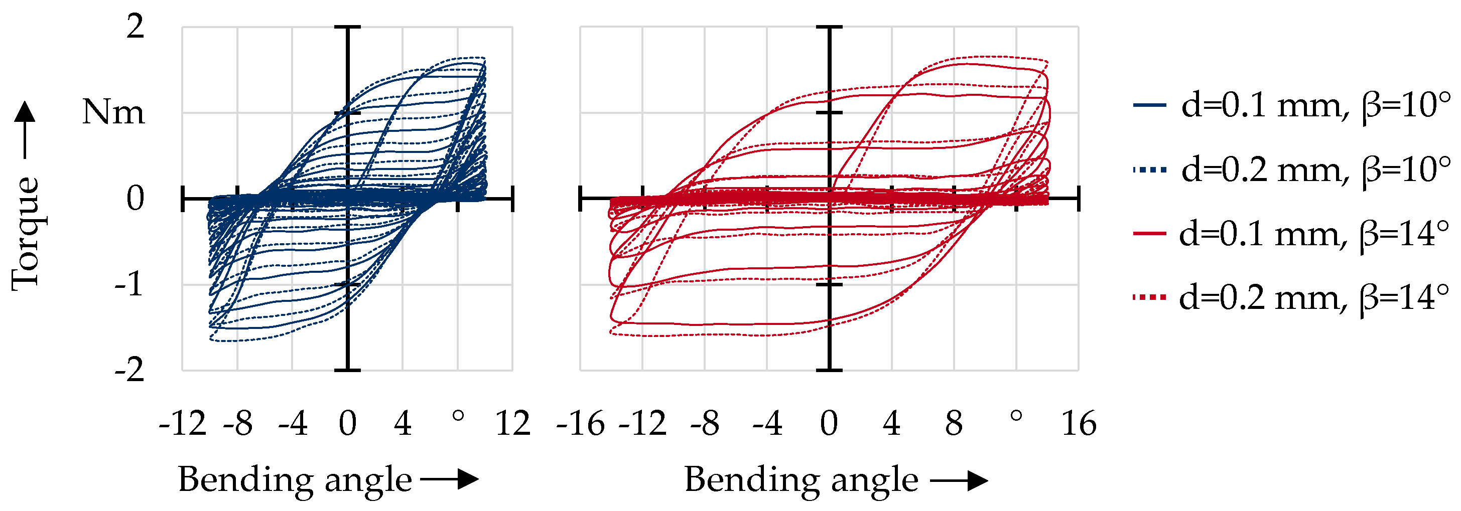
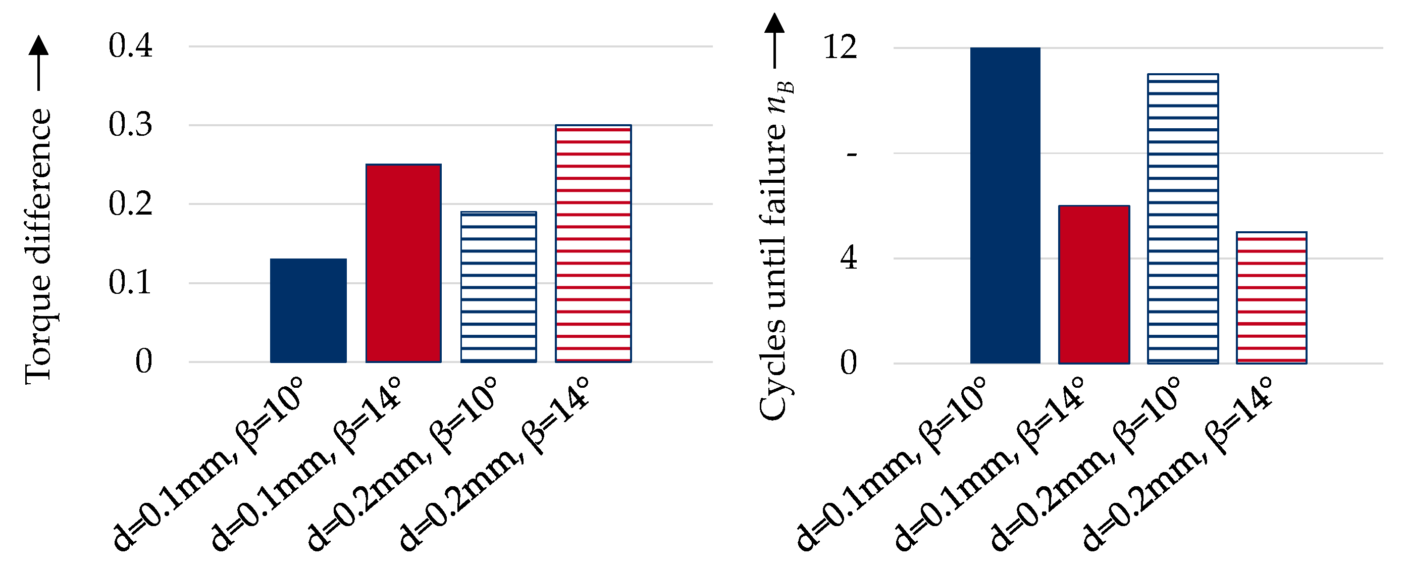
3.1.2. Characteristics of Cyclic Bending of Wire Strip Produced by Notch Rolling
3.2. Characteristics of Stamped Wire Strip
4. Discussion
4.1. Interaction of Notch Rolling and Cyclic Bending
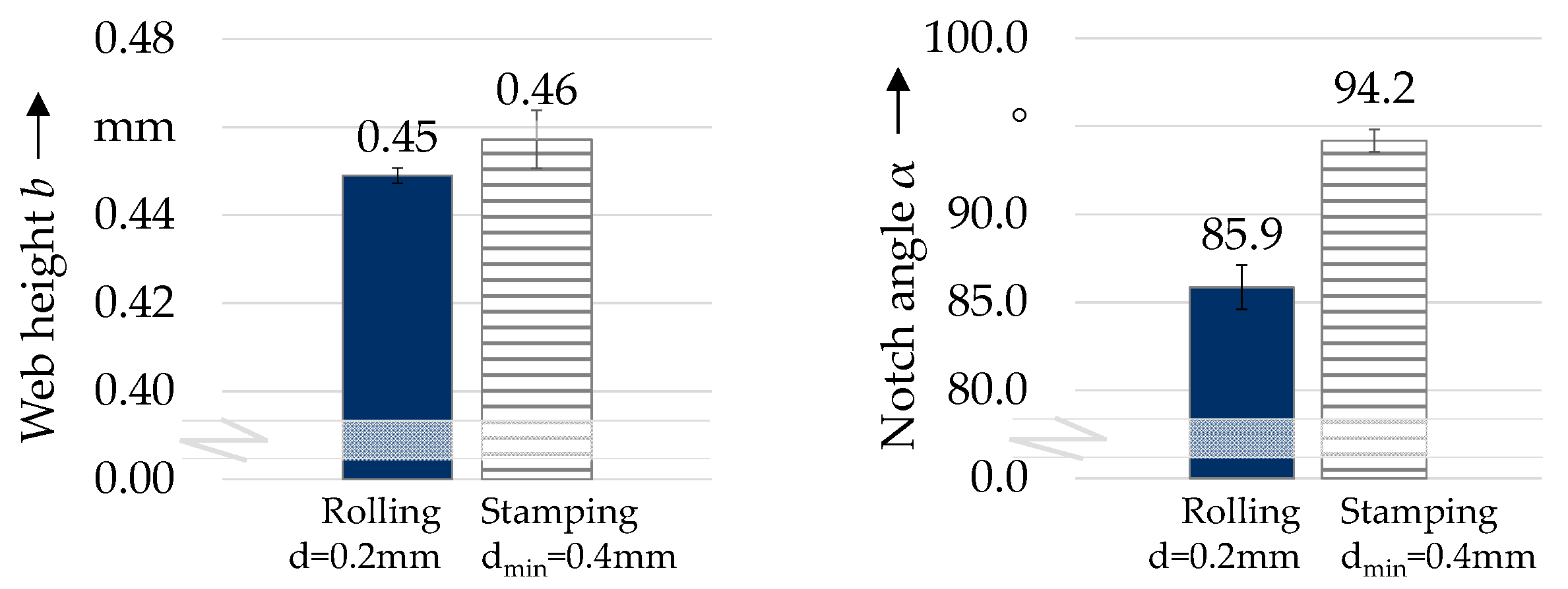
4.2. Differences in Rolled and Stamped Wire Strip
4.3. Equivalent of Rolled Wire Strip by Stamped Wire Strip
- Web height b;
- Notch angle α; and
- Hardening distribution.
- Web height b: The web height is considered identical for rolled and stamped wire strip. Inference from dmin to b is possible (difference of 0.6 mm);
- Notch angle α: To reach similar results, the tool’s notch angle αt has to be adjusted based on derived Equations (2) and (4);
- Hardening distribution: Outer notch is tested during cyclic bending due to similar hardness distribution.
5. Conclusions and Outlook
Author Contributions
Funding
Data Availability Statement
Acknowledgments
Conflicts of Interest
References
- Le Hoang, A.; Fehling, E. Influence of steel fiber content and aspect ratio on the uniaxial tensile and compressive behavior of ultra high performance concrete. Constr. Build. Mater. 2017, 153, 790–806. [Google Scholar] [CrossRef]
- Zheng, Y.; Wu, X.; He, G.; Shang, Q.; Xu, J.; Sun, Y. Mechanical Properties of Steel Fiber-Reinforced Concrete by Vibratory Mixing Technology. Adv. Civ. Eng. 2018, 11, 9025715. [Google Scholar] [CrossRef] [Green Version]
- Kusumawardaningsih, Y.; Fehling, E. Behavior of Ultra High Performance Concrete (UHPC) Confinement on Normal Strength Concrete (NSC) Columns. In Proceedings of the International Symposium on Ultra High Performance Concrete, Kassel, Germany, 13–15 September 2004. [Google Scholar]
- Mark, P.; Oettel, V.; Look, K.; Empelmann, M. Neuauflage DAfStb-Richtlinie Stahlfaserbeton. Beton Stahlbetonbau 2021, 1, 19–25. [Google Scholar] [CrossRef]
- Huss, M. Neuer Stahlfasertyp eröffnet vielfältige Möglichkeiten für die Betonindustrie. BetonWerk Int. 2018, 5, 72–76. [Google Scholar]
- Stahl, K.-H. Method for Producing Steel Fibers. U.S. Patent 9630226B2, 28 January 2010. [Google Scholar]
- Dehn, F.; König, G.; Marzahn, G. Konstruktionswerkstoffe im Bauwesen; Ernst & Sohn: Berlin, Germany, 2003. [Google Scholar]
- Huss, M.; Reichel, M.; Techen, H. Innovative Stahlfaser für die Beton- und Fertigteilindustrie. BetonWerk Int. 2018, 4, 50–52. [Google Scholar]
- Marcalíková, Z.; Procházka, L.; Pešata, M.; Boháčová, J.; Čajka, R. Comparison of Material Properties of Steel Fiber Reinforced Concrete with Two Types of Steel Fiber. IOP Conf. Ser. Mater. Sci. Eng. 2019, 549, 012039. [Google Scholar] [CrossRef]
- Biallas, A.; Merklein, M. Interaction analysis of a notching and cyclic bending process. Manuf. Lett. 2022, 33, 167–173. [Google Scholar] [CrossRef]
- Biallas, A.; Merklein, M. Material Model for the Production of Steel Fibers by Notch Rolling and Fulling. Key Eng. Mater. 2021, 883, 277–284. [Google Scholar] [CrossRef]
- Wietek, B. Faserbeton; Springer Fachmedien Wiesbaden: Wiesbaden, Germany, 2020. [Google Scholar]
- Merklein, M.; Kuppert, A. A method for the layer compression test considering the anisotropic material behavior. Int. J. Mater. Form. 2009, S1, 483–486. [Google Scholar] [CrossRef]
- Hockett, J.; Sherby, O. Large strain deformation of polycrystalline metals at low homologous temperatures. J. Mech. Phys. Solids 1975, 2, 87–98. [Google Scholar] [CrossRef]
- Biallas, A.; Merklein, M. Evaluation of Material Behavior of Wire Strips under Cyclic Bending Load and Preparation of An Experimental Test Method. In Proceedings of the 24th International Conference on Material Forming, Liège, Belgium, 14–16 April 2021; Available online: https://popups.uliege.be/esaform21/index.php?id=3826 (accessed on 1 December 2022).
- Liao, D.; Zhu, S.-P.; Correia, J.; de Jesus, A.M.P.; Berto, F. Recent advances on notch effects in metal fatigue: A review. Fatigue Fract. Eng. Mater. Struct. 2020, 4, 637–659. [Google Scholar] [CrossRef]
- Omiya, M.; Arakawa, S.; Yao, Z.; Muramatsu, M.; Nishi, S.; Takada, K.; Murata, M.; Okato, K.; Ogawa, K.; Oide, K.; et al. Influence of strength and notch shape on crack initiation and propagation behavior of advanced high strength steel sheets. Eng. Fract. Mech. 2022, 6, 108573. [Google Scholar] [CrossRef]
- Ghosal, P.; Paul, S.; Das, B.; Chinara, M.; Arora, K. Notch fatigue performance of DP600 steel under different pre-straining paths. Theor. Appl. Fract. Mech. 2020, 12, 102630. [Google Scholar] [CrossRef]


| Influencing Parameters | Rolling Gap d | Bending Angle β |
|---|---|---|
| Stage A | 0.1 mm | 10° |
| Stage B | 0.2 mm | 14° |
| Parameter | Symbol | Unit | Set 1 | Set 2 | Set 3 | Set 4 |
|---|---|---|---|---|---|---|
| Process variables—Input | ||||||
| Rolling gap | d | mm | 0.10 | 0.10 | 0.20 | 0.20 |
| Bending angle | β | ° | 10 | 14 | 10 | 14 |
| Wire strip—Output/Input | ||||||
| Notch tip radius | rk | mm | 0.032 | 0.032 | 0.032 | 0.032 |
| Notch angle | α | ° | 85.2 | 85.2 | 85.9 | 85.9 |
| Web height | b | mm | 0.43 | 0.43 | 0.45 | 0.45 |
| Notch hardness | hrd | HV | 392 | 392 | 368 | 368 |
| Separated wire strip—Output | ||||||
| Amount of cycles | nB | - | 12 | 6 | 11 | 5 |
| Torque maximum | Nmax,1 | Nm | 1.57 | 1.57 | 1.64 | 1.64 |
| Torque difference | Nmax,1–Nmax,2 | Nm | 0.13 | 0.25 | 0.19 | 0.30 |
| Curvature diameter | D | mm | 0.63 | 0.55 | 0.71 | 0.52 |
| Parameter | Symbol | Unit | Set 1 | Set 2 |
|---|---|---|---|---|
| Process variable—Input | ||||
| Min. tool distance | dmin | mm | 0.30 | 0.50 |
| Wire strip—Output | ||||
| Notch tip radius | rk | mm | 0.045 | 0.044 |
| Notch angle | α | ° | 92.9 | 96.7 |
| Web height | b | mm | 0.36 | 0.56 |
| Notch hardness (middle) | hrd | HV | 340 | 305 |
Disclaimer/Publisher’s Note: The statements, opinions and data contained in all publications are solely those of the individual author(s) and contributor(s) and not of MDPI and/or the editor(s). MDPI and/or the editor(s) disclaim responsibility for any injury to people or property resulting from any ideas, methods, instructions or products referred to in the content. |
© 2023 by the authors. Licensee MDPI, Basel, Switzerland. This article is an open access article distributed under the terms and conditions of the Creative Commons Attribution (CC BY) license (https://creativecommons.org/licenses/by/4.0/).
Share and Cite
Biallas, A.; Ohmayer, S.; Merklein, M. Fundamental Investigations to Evaluate the Influence of Notching Processes on a Subsequent Cyclic Bending Process for the Production of Wire Cores. J. Manuf. Mater. Process. 2023, 7, 24. https://doi.org/10.3390/jmmp7010024
Biallas A, Ohmayer S, Merklein M. Fundamental Investigations to Evaluate the Influence of Notching Processes on a Subsequent Cyclic Bending Process for the Production of Wire Cores. Journal of Manufacturing and Materials Processing. 2023; 7(1):24. https://doi.org/10.3390/jmmp7010024
Chicago/Turabian StyleBiallas, Alina, Sophia Ohmayer, and Marion Merklein. 2023. "Fundamental Investigations to Evaluate the Influence of Notching Processes on a Subsequent Cyclic Bending Process for the Production of Wire Cores" Journal of Manufacturing and Materials Processing 7, no. 1: 24. https://doi.org/10.3390/jmmp7010024