Next Article in Journal
Modeling of Surface Roughness in Honing Processes by Using Fuzzy Artificial Neural Networks
Previous Article in Journal
Three-Body Abrasive Wear-Resistance Characteristics of a 27Cr-Based 3V-3Mo-3W-3Co Multicomponent White Cast Iron with Different Ti Additions
 
 
Correction published on 26 April 2023, see J. Manuf. Mater. Process. 2023, 7(3), 85.
Article

Multi-Response Optimization of Ti6Al4V Support Structures for Laser Powder Bed Fusion Systems

by
Antonios Dimopoulos
1,*,
Ilias Zournatzis
2,
Tat-Hean Gan
1,3 and
Panagiotis Chatzakos
2
1
Department of Mechanical and Aerospace Engineering, Brunel University London, Uxbridge UB8 3PH, UK
2
TWI Hellas, Leof. Kifisias 280, 152 32 Chalandri, Greece
3
TWI Ltd., Granta Park, Great Abington, Cambridge CB 21 6AL, UK
*
Author to whom correspondence should be addressed.
J. Manuf. Mater. Process. 2023, 7(1), 22; https://doi.org/10.3390/jmmp7010022
Submission received: 1 December 2022 / Revised: 5 January 2023 / Accepted: 10 January 2023 / Published: 13 January 2023 / Corrected: 26 April 2023

Abstract

:
Laser Powder Bed Fusion (LPBF) is one of the most commonly used and rapidly developing metal Additive Manufacturing (AM) technologies for producing optimized geometries, complex features, and lightweight components, in contrast to traditional manufacturing, which limits those characteristics. However, this technology faces difficulties with regard to the construction of overhang structures and warping deformation caused by thermal stresses. Producing overhangs without support structures results in collapsed parts, while adding unnecessary supports increases the material required and post-processing. The purpose of this study was to evaluate the various support and process parameters for metal LPBF, and propose optimized support structures to minimize Support Volume, Support Removal Effort, and Warping Deformation. The optimization approach was based on the Design of Experiments (DOE) methodology and multi-response optimization, by 3D printing and studying overhang geometries from 0° to 45°. For this purpose, EOS Titanium Ti64 Grade 5 powder was used, a Ti6Al4V alloy commonly employed in LPBF. For 0° overhangs, the optimum solution was characterized by an average Tooth Height, large Tooth Top Length, low X, Y Hatching, and high Laser Speed, while for 22.5° and 45° overhangs, it was characterized by large Tooth Height, low Tooth Top Length, high X, Y Hatching, and high Laser Speed.

1. Introduction

Over the last decade, AM has been growing in popularity due to the unparallel design freedom it enables [1,2], and has been considered one of the main drivers of the Industry 4.0 production paradigm shift [1,2]. Based on recent reports, the AM industry was valued at approximately USD 12 million in 2021, and is expected to grow to USD 35 million by 2028, with a Compound Annual Growth Rate (CAGR) of 20.5% [3].
Laser Powder Bed Fusion is one of the most widely used metal AM processes, capable of producing complex, thin, and lightweight components, which are essential properties for industries such as aerospace, biomedical, defense, and automotive [4,5]. Various materials can be used in LPBF, such as aluminum and titanium, while the mechanical properties of the produced parts can be similar to or even better than those of parts manufactured via traditional methods, such as machining and molding [4]. In LPBF, a laser beam selectively melts powder in a powder bed, several melting tracks are strung together in a micro-welding process, and a 3D component is created inside the powder envelope where several of these layers are fused together [4,5]. However, because 3D printing builds the part layer upon layer, this method faces difficulties with regard to the construction of overhang structures and the warping deformation caused by thermal stresses. It could be assumed that the unmelted powder around the part is able to support the overhang structures and eliminate the need for external supports. However, Poyraz et al. [6] and Bo and Chou [7] found that this was not feasible since the unmelted powder is not thermally conductive, and results in various quality-related problems such as curling, warping, and distortion, especially in overhang areas where the highest temperatures are observed.
For that reason, support structures are always required, since they anchor the part to the build plate, offer a suitable platform for the next layer to be built upon, and act as a heat sink that allows the part to cool at a more controlled rate. Therefore, producing an object without support structures results in distorted and collapsed parts, while the addition of unnecessary supports increases the post-processing, the time and effort needed to remove the supports, the risk to damage of the part, and the amount of material required. Appropriate software and design guidelines [8] can be implemented to minimize the aforementioned problems, but they cannot eliminate the support structures. Thus, the optimization of the supports is important for minimizing the material required to build the supports, and the time and effort needed to remove them, while maintaining the quality of the printed part based on high standards.
Significant research has been conducted over the past years on the support structure’s design and optimization in metal AM, aiming to reduce the amount of supports required and propose innovative solutions for easy removal without affecting the quality of the printed part. Ameen et al. 2021 [9] investigated and evaluated different support parameters for Electron Beam Melting (EBM) by using multi-objective genetic algorithms such as Response Surface Methodology (RSM), Analysis of Variance (ANOVA), and MOGA-II, aiming to propose support structures that are easy to remove and consume less support material without affecting the quality of the part. It was found that the optimal solution was characterized by a large tooth height (4 mm), large tooth base interval (4 mm), large fragmented separation width (2.5 mm), high beam current (6 mm), and low beam scan speed (1200 mm/s). Wadea et al., 2020 [10] also examined the effect of different support structure designs on the removal of unmelted powder from EBM overhang structures, aiming to reduce material waste and prevent support structures from having any closed hollow volume which would be filled by unmelted powder. The results showed that it is possible to optimize the powder removal through optimization of the support structure design parameters. Jukka-Pekka et al., 2014 [11], by using Selective Laser Melting (SLM) technology, investigated and compared the properties of two different support structures, web and tube, aiming to examine the removability of the supports and the surface quality of the part. It was observed that the removability of web supports was much better than tube supports. Ahmed et al., 2013 [12] used Direct Metal Laser Sintering (DMLS) technology to examine the geometry of supports and proposed optimized lattice support structures in order to reduce the support material and the build time while fulfilling the structural demands required of a metallic support structure. It was found that supports with a very low volume can save a significant amount of support material and significantly reduce the build time. Poyraz et al., 2015 [6] examined the effects of different design parameters on block-type supports, applied to prismatic specimens manufactured using DMLS. The aim of this study was to provide guidance for designing optimized support structures capable of reducing the amount of material required, production time, and post-processing efforts. Lindecke et al., 2018 [13] investigated, through experiments on SLM, the strength of the connection between optimized support structures and the part, aiming to reduce the material consumption and the effort required during post-processing to remove the supports. Based on the results, a series of guidelines were proposed, aimed at helping process engineers to select the right design of the support structure when preparing a print job. Among others, alternative but equally significant solutions have also been proposed for minimizing the support amount and reducing the post-processing. Cloots et al., 2013 [14], developed a component segmentation strategy that allows the segmentation of critical areas of the component by applying a specific scanning strategy with appropriate energy input, and optimized supporting strategies, aiming to avoid massive support structures and reduce post-processing effort without affecting the quality of the part. Jamasp et al., 2011 [15] proposed an innovative laser manufacturing method by combining pulsed and continuous modes of radiation aiming to build support structures that are easy to remove while having sufficient mechanical properties to withstand deformation and evacuate heat. Qiqiang et al., 2020 [16] studied the removability of metal support structures by milling, comparing different cutting lengths, and developing a finite element method (FEM) model to explain the support removal mechanisms, while Lefky et al., 2017 [17] proposed an alternative way to remove the support structures, examining, for the first time, an approach for dissolvable supports in Powder Bed Fusion (PBF)-printed metal parts. Zeng, 2015 [18] developed a novel framework for a support structure generation and optimization tool to overcome the difficulty of dealing with support structures in SLM. Seven sets of experiments were investigated using uniform and non-uniform support structures capable of withstanding thermal stresses at critical locations while minimizing the overall need for material.
Based on the literature referenced above, it is clear that overhang surfaces in metal AM are strongly connected to the support structures, since well-designed and optimized supports result in minimizing the material required, the removal time, the effort needed during post-processing, the printing time, and the risk to damage of the part. Although most of the aforementioned studies refer to the SLM process, much more work has been conducted for EBM regarding the investigation of the various support parameters and their effects on the printed part. In this research, an innovative design approach for effortless, reliable, and sustainable AM was proposed. For the first time, optimized support structures for LPBF that are easy to remove and that consume the minimum amount of support material without affecting the quality of the part were investigated. The optimization approach focused on the evaluation of the various support and process parameters, by using design of experiments methodology and relevant optimization algorithms.

2. Methodology

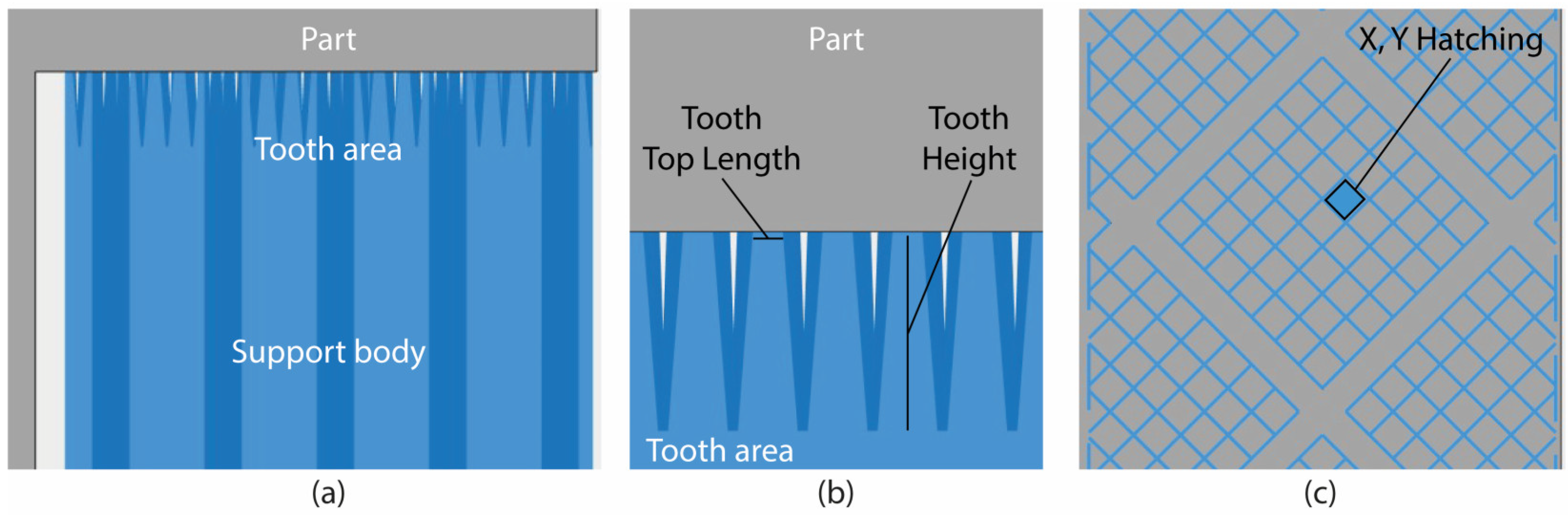
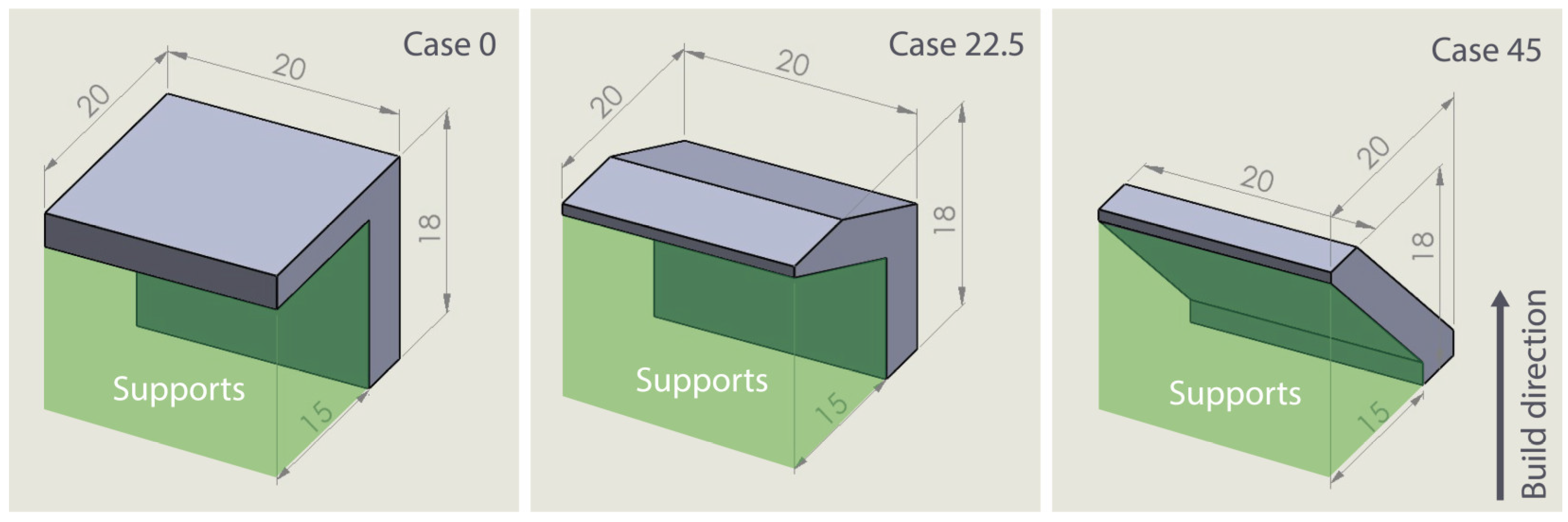
2.1. Design of Experiments (DOE)
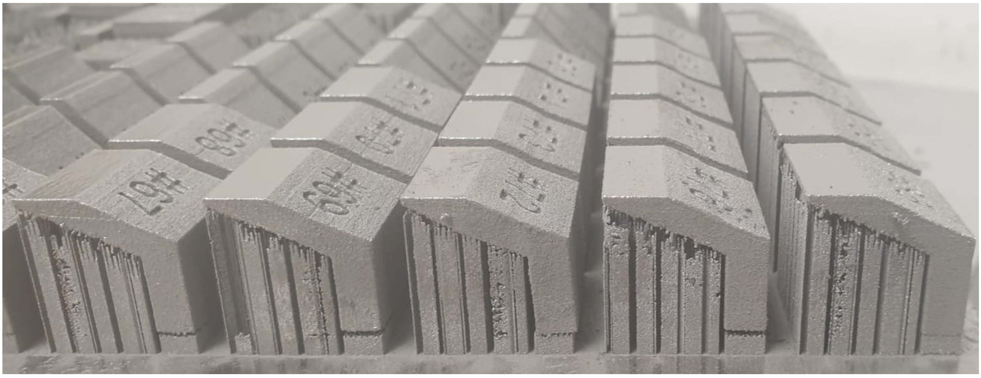
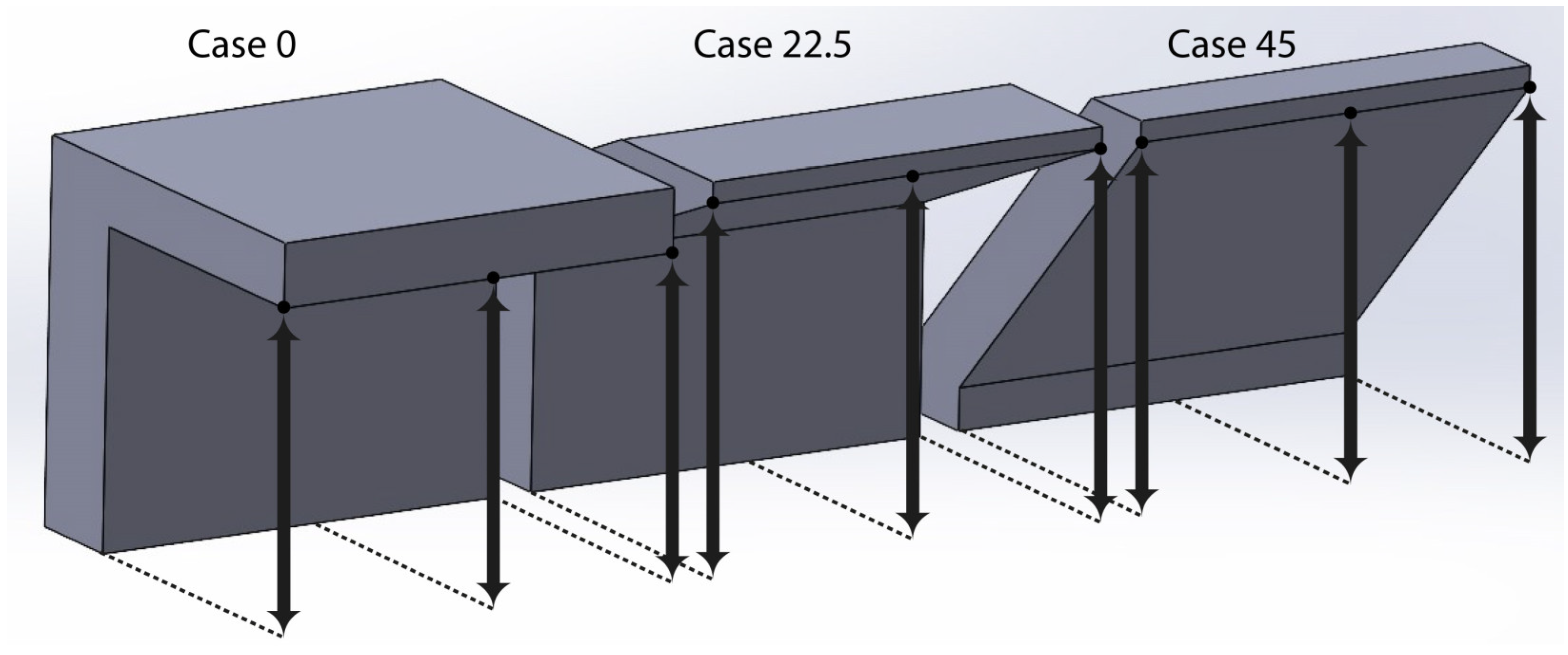
In metal AM and LPBF, there is a wide range of support types available, such as block, point, web, contour, and line [6,11]. Their choice depends on the geometry and the features of the part, the selected material, and the compatible slicing software [19]. According to the literature, the most commonly used support type is LPBF, and the one that was investigated in this research is the block type. Fragmented block-type supports are preferred for a wide range of applications, since their configurable morphology is ideal for reducing material consumption and removal effort. A sample of their morphology is shown in Figure 1. It can be observed that they are divided into two parts: the support body, which is the main geometry of the support structures; and the tooth area, which is based on the contact area between the supports and the part’s overhang surface, as illustrated in Figure 1a.
After the selection of the support type, the next step is to identify the input parameters (free variables that can be changed and controlled) and their respective levels. Based on the literature and a series of screening experiments and printings, four main areas were selected for investigation: (i) the tooth area, including Tooth Height and Tooth Top Length as shown in Figure 1b, (ii) the support main body including X, Y Hatching as shown in Figure 1c, (iii) the process parameters including Laser Speed, and (iv) the specimen geometry obtained by generation of different Overhang Angles. Table 1 illustrates the selective parameters and their respective levels. Each parameter contains three levels: the minimum, the average, and the maximum value.
To be able to evaluate the effect of the aforementioned parameters on the support structures, ledge overhang specimens were designed, based on the published works referenced above. Three different specimens were selected (case 0°, case 22.5°, and case 45°) according to the respective Overhang Angle levels. The specimens’ geometry, their dimensions in mm, the Overhang Angles followed by the supported area, and the build direction of the parts are shown in Figure 2.
During the Design of Experiments (DOE) of the imported values (Table 1.), Response Surface Methodology (RSM) based on Central Composite Design (CCD) was used to perform the experiments and define the different configurations. This method was selected since, based on the literature review, it is especially useful in the analysis and optimization of responses [9]. According to the parameters and their levels, a total number of 90 alternatives (or runs) were performed. Concerning the CCD setup, 2 replicates of factorial points, 2 replicates of axial points, and 6 replicates of center points were used. A face-centered approach was followed with an alpha value equal to 1. The software used to prepare the DOE and visualize the optimization results was Design-Expert 13.

2.2. Printings

For the needs of the experiments, an EOS M290 machine with a Yb-fiber laser of 400 W and focus diameter of 100 μm based on the SLM process was used for fabricating the specimens. SLM, also known as DMLS or LPBF for metals, belongs to the Powder Bed Fusion (PBF) technique [5,20]. In LPBF, a laser beam energy source selectively melts and fuses powder material in a layer-by-layer manner into a desired shape. Afterwards, the molten material solidifies and cools down quickly, and the consolidated material starts to form the part. Next, the build platform is lowered by an amount equal to the layer thickness, and a new layer of powder is deposited by the recoater across the build platform. The process is repeated until the solid 3D part is formed [5,21].
In the current research, the specimens were built by using the optimum parameters of the EOS M290 machine as suggested by the manufacturer, while a layer thickness of 60 μm was applied. The various support structures were built based on the parameters shown in Table 1, followed also by some constant parameters such as 0.1 mm tooth base interval, 1 mm tooth base length, 0.06 mm Z offset, 0.2 mm thickness, 8 mm fragmentation interval, 1 mm separation width, and 45° supports rotation angle (Table 2). The material used was the EOS Titanium Ti64 Grade 5 in powder form, a strong and lightweight Ti6Al4V alloy with excellent corrosion resistance, a generic particle size distribution of 20–80 μm, and powder chemical composition of Ti (balance), AI (5.50–6.75 wt%), V (3.50–4.50 wt%), and 1.05 wt% of other elements.
Materialise Magics and EOS Print were used to generate the various support structures and perform the final slicing jobs. Figure 3 illustrates the printed outcome after the removal of the unmelted powder. In total, 68 out of 90 specimens were printed successfully, while the remaining 22 failed during the fabrication process due to blade crashing. It was also observed that all of the non-printed specimens belonged to case 0 (Level 1—Overhang Angle 0°). Regarding the support parameters, X, Y Hatching had the most significant effect on the non-printed specimens, since 16 out of 22 consisted of the maximum hatching distance (2.5 mm). The non-printed specimens were not excluded from this study and were considered in the analysis and optimization as printing failures.

2.3. Performance Measures

To evaluate the performance of the various support structures, three responses were investigated: Support Structure Volume, Support Structure Removability, and Warping Deformation. The volume was measured using the online platform “viewstl.com”. The support structures were exported from Magics in STL format, imported into the platform one by one, and their volume was calculated. For better interpretation, the data were normalized from 1 (minimum volume) to 5 (maximum volume).
The removability was evaluated according to the effort needed to remove the supports and clean the overhang surface of support remnants. It is worth mentioning here that most of the support structures were removed while detaching the specimens from the build plate. The rest were removed manually using basic tools such as wire cutters, pliers, and files. Three different conditions were considered to evaluate the removability. In “condition 1”, supports were very easy to remove and not much effort was needed to clean the surface. In “condition 2”, supports were easy to remove but more effort was needed to clean the surface. In “condition 3”, supports were very difficult to remove manually, risking the quality of the printed part. These three conditions are illustrated in Figure 4. The non-printed specimens were not included in the removability evaluation.
The warping deformation was evaluated by measuring the displacement of the overhang surfaces. The distance of the lower overhang edge was measured in three different points by using a digital caliper considering as a reference the base of the non-overhang area as shown in Figure 5. The final warping deformation for each specimen occurred after calculating the average displacement of the three points. The minimum displacement was observed at 0.13 mm, while the maximum was observed at 1.83 mm. The non-printed specimens were included in the warping evaluation as failed prints and represented in the data analysis by a typical value of “2”. During the numerical optimization, these specimens, as well as those with high warping deformation, were filtered and excluded.
After the evaluation of performance measures for all the specimens, the findings were imported into Design-Expert 13, where Analysis of Variance (ANOVA) was performed towards the analysis of the imported data and the validation of the selected model. Multi-response optimization was also performed to detect the optimal parameters for each overhang case that minimized Support Volume and Support Removal Effort while eliminating the warping deformation.

3. Results and Discussion

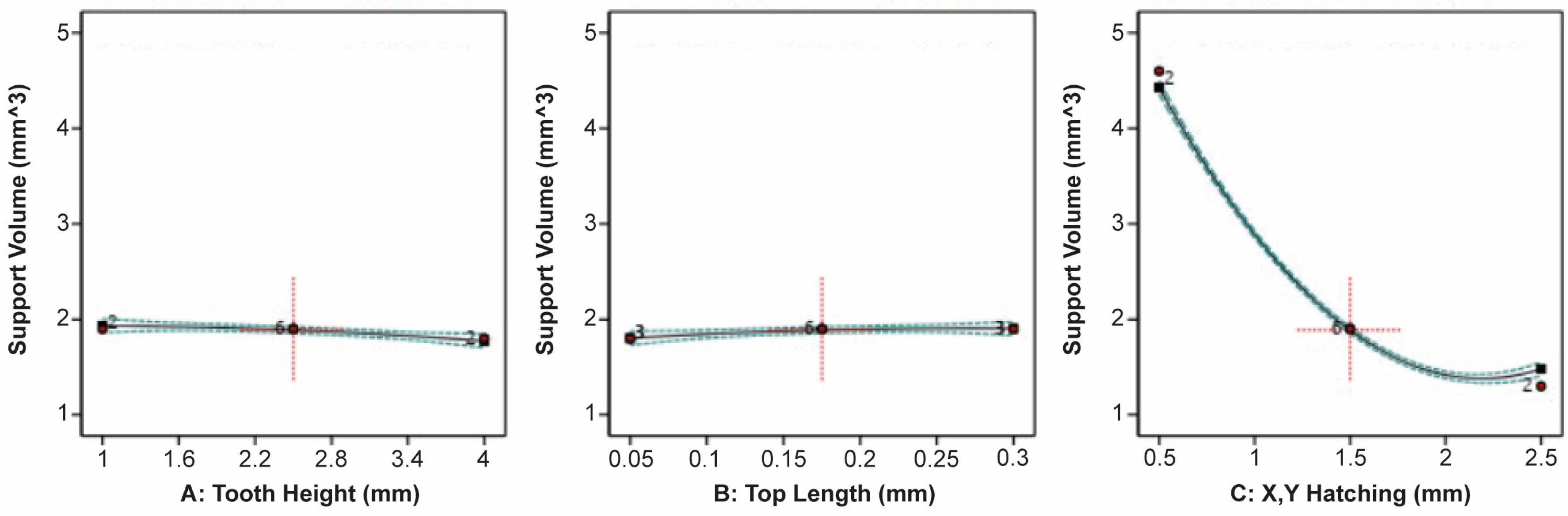
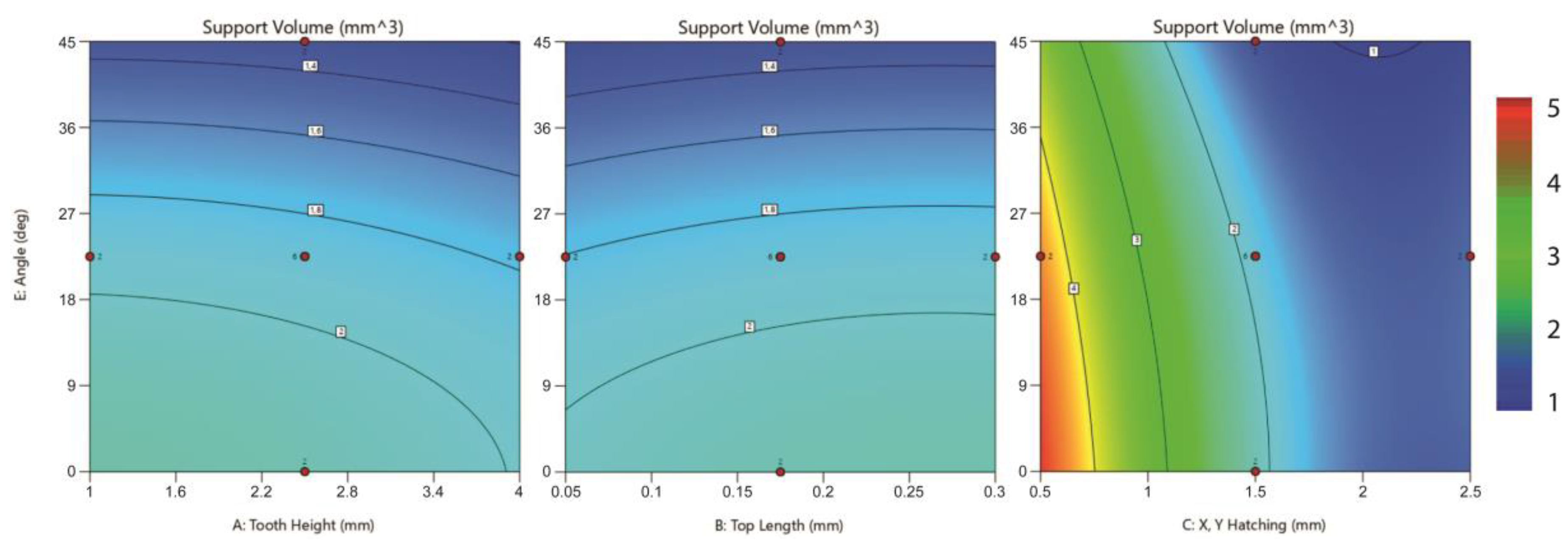
3.1. Support Volume Analysis

For the in-depth analysis of Support Volume, a quadratic model was selected with Adjusted R2 = 0.9972 and Predicted R2 = 0.9962, which indicates a reasonable agreement (Table 3). The results of ANOVA are presented in Table 4. The F-value of 1605.40 with p-value < 0.05 implies that the model is significant. In this case, A, B, C, E, AB, AC, BC, CE, C2, and E2 are significant model terms. On the other hand, a p-value greater than 0.1000 implies that the model terms are not significant. Adeq Precision (Table 3) measures the signal-to-noise ratio. A ratio greater than four is desirable. In this case, a ratio of 112.346 indicates an adequate signal. Based on the above criteria, the quadratic model of Support Volume was approved for further analysis.
The ANOVA results showed that Tooth Height (A), Tooth Top Length (B), and X, Y Hatching (C), as well as their interactions, have a significant effect on Support Volume. According to Sum of Squares, X, Y Hatching has by far the most significant effect, while Laser Speed (D) is completely independent. Overhang Angel (E) also has a significant effect on Support Volume; however, this is due to the three different specimens’ geometries used and the unequal volume of their supported area.
The effect of Tooth Height, Tooth Top Length, and X, Y Hatching on Support Volume is illustrated clearly in Figure 6. It was found that as Tooth Height increases and Tooth Top Length decreases, Support Volume barely decreases. On the other hand, as X, Y Hatching increases, Support Volume decreases extremely. This is because a significant amount of material is removed from the support structure’s main body as the total number of inner walls decreases. Thus, it was observed that the minimum support volume for all the specimens could be achieved at higher levels of Tooth Height (4 mm), lower levels of Tooth Top Length (0.05 mm), and higher levels of X, Y Hatching (2.5 mm). This is also observed in Figure 7, where relative contour plots illustrate the interaction between the support parameters and the different Overhang Angles on Support Volume.

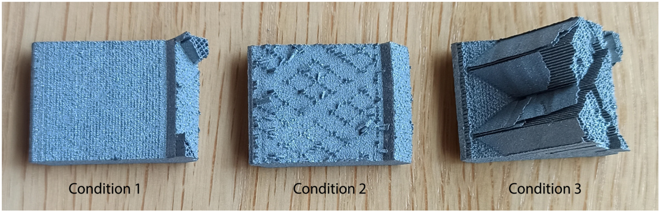
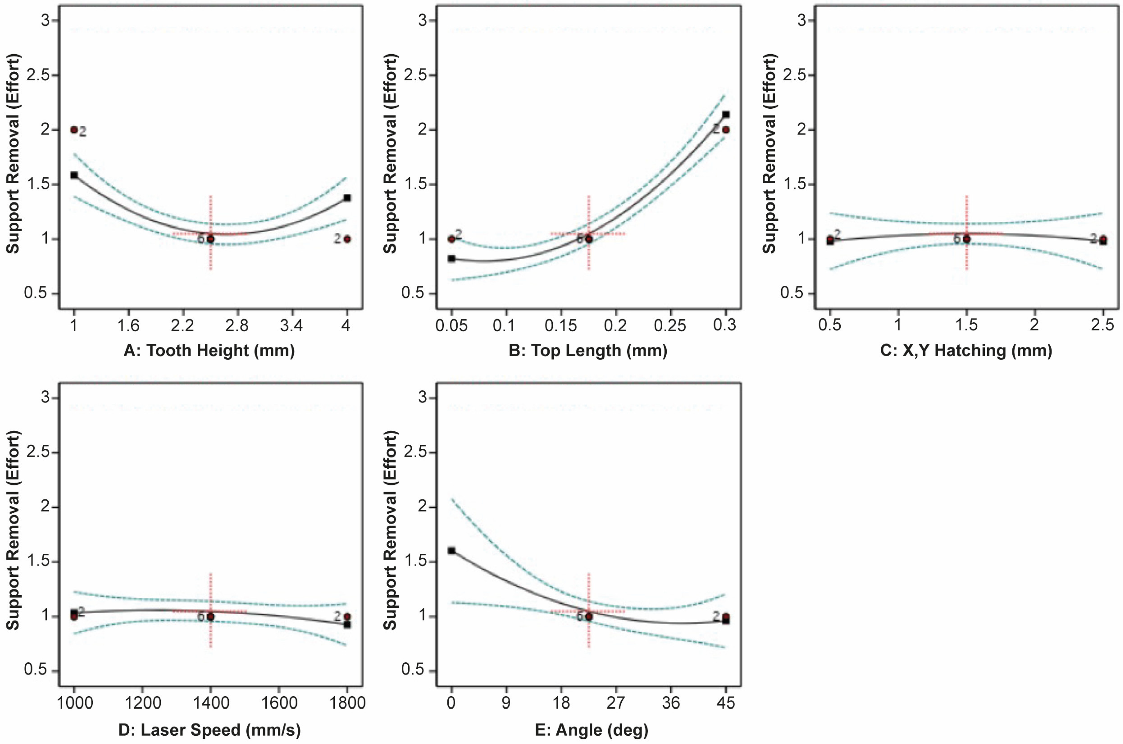
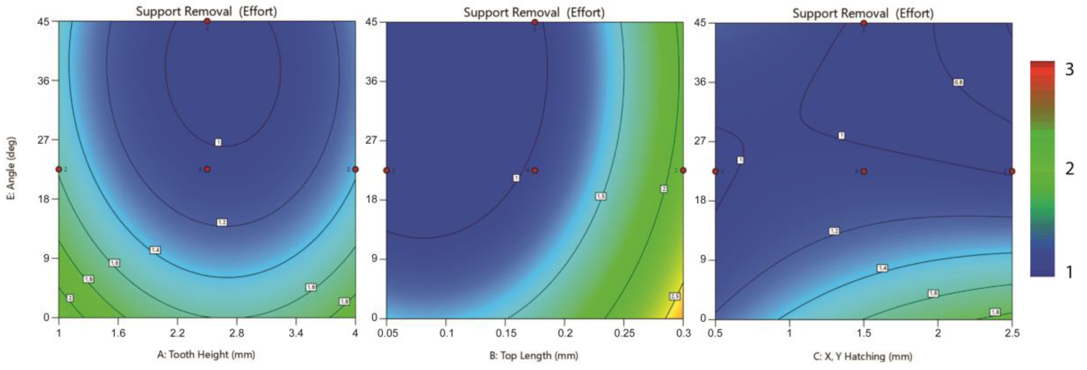
3.2. Support Removal Effort Analysis

For the analysis of Support Removal Effort, a quadratic model was also selected with Adjusted R2 = 0.9529 and Predicted R2 = 0.9323, which indicates a reasonable agreement (Table 5). The non-printed parts were ignored for this analysis. In Table 6., the results of the ANOVA test are presented. The F-value of 68.75 with p-value < 0.05 implies that the model is significant. A, B, E, AC, BC, CE, A2, and B2 are the significant model terms, while those with p-value > 0.1000 are not significant. In addition, the Adeq Precision rate of 22.3995 (greater than 4) indicates an adequate signal (Table 5). Based on the above, the quadratic model of Support Removal Effort was also approved for further analysis.
Regarding the ANOVA results, it was observed that Tooth Height (A), Tooth Top Length (B), and Overhang Angle (E), along with a few interactions, have a significant effect on Support Removal Effort. The Sum of Squares indicates that Tooth Top Length has the most significant effect compared to the other parameters, while X, Y Hatching (C) and Laser Speed (D) do not significantly affect the removal effort.
The effect of Tooth Height, Tooth Top Length, X, Y Hatching, Laser Speed, and Overhang Angle on Support Removal Effort is illustrated in Figure 8. It can be seen that Support Removal Effort decreases for average values of Tooth Height. It was also found that as Tooth Top Length decreases, the removal effort decreases greatly. This is because, at higher levels of Tooth Top Length, the bonding area between the part and supports was stronger, and as a result, the supports were difficult to remove. In addition, extra effort was needed to extract metal remnants from the surface. X, Y Hatching and Laser Speed barely affected the removal effort, while it can be observed that Support Removal Effort decreases as Overhang Angle increases.
The interaction of the support parameters and the different Overhang Angles on the Support Removal Effort are shown in Figure 9. It was found that the minimum removal effort could be achieved at average values of Tooth Height (2.5 mm), lower levels of Tooth Top Length (0.05 mm), and higher levels of Overhang Angle (45°). For 0° overhangs, the removal effort decreases at lower levels of X, Y Hatching (0.5 mm), while for bigger overhangs, the removal effort decreases at higher levels of X, Y Hatching (2.5 mm). Various Laser Speed values can be used without significantly affecting the removal effort.

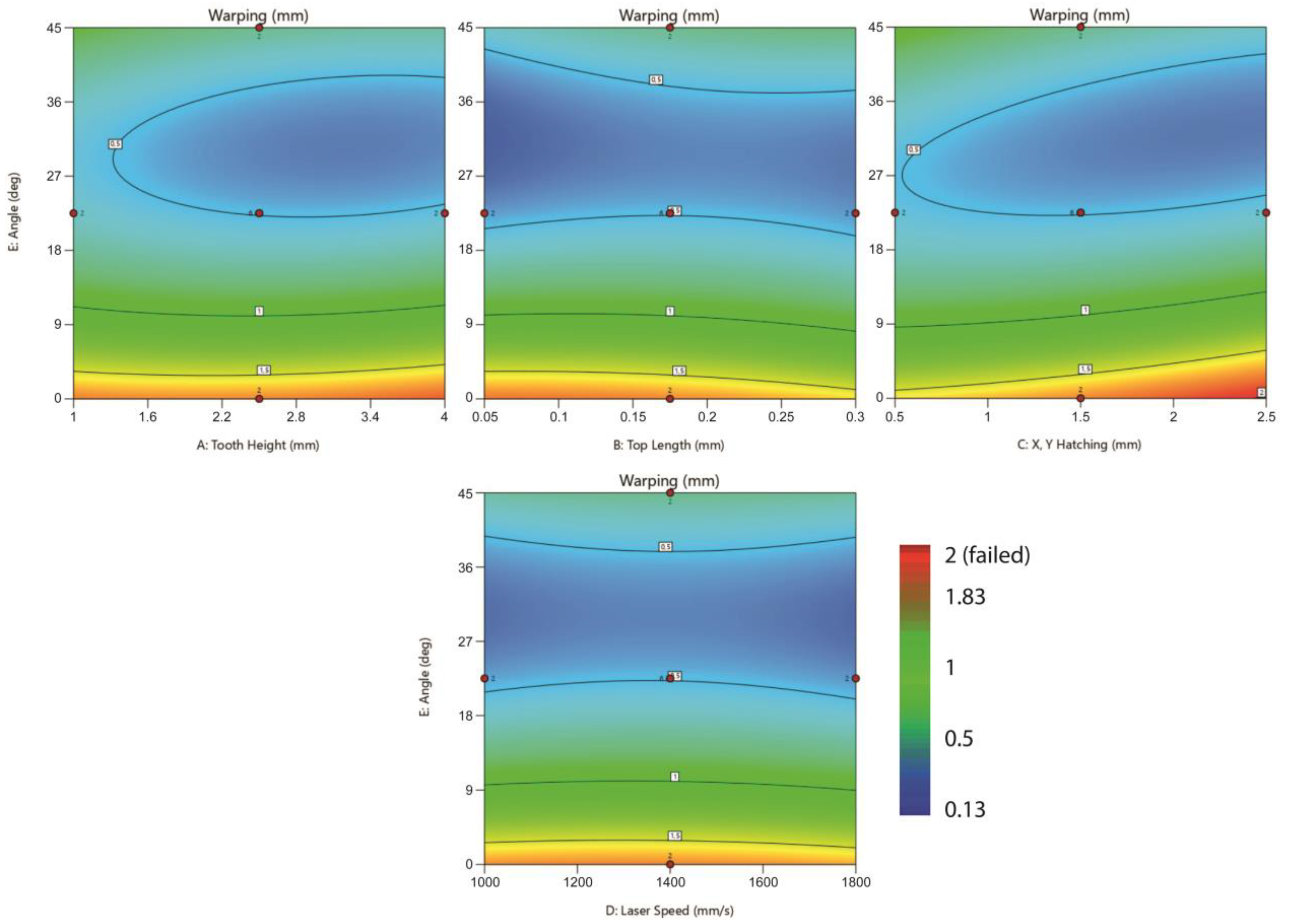
3.3. Warping Deformation Analysis

The analysis of Warping Deformation was also based on a quadratic model. The Adjusted R2 = 0.8069 and Predicted R2 = 0.7403 indicate a reasonable agreement, since their difference is less than 0.2 (Table 7). The non-printed parts were included in this analysis and are represented by a typical value of “2”, which actually means fully warped and defective parts. Table 8 illustrates the results of the ANOVA test. The F-value of 19.59 with p-value < 0.05 implies that the model is significant. The results show that E, AE, BC, BE, CE, and E2 are the significant model terms, while terms with a p-value greater than 0.1000 are not significant. The Adeq Precision = 14.2794 (Table 7) indicates an adequate signal; thus, the quadratic model was approved for further analysis.
The ANOVA results showed that Overhang Angle (E), along with its interactions, has a significant effect on Warping Deformation. Compared to the other parameters, Sum of Squares indicates that Overhang Angle has the most significant effect, while the other parameters barely affect Warping Deformation.
The effect of Tooth Height, Tooth Top Length, X, Y Hatching, Laser Speed, and Overhang Angle on Warping Deformation is illustrated in Figure 10. It can be observed that Warping Deformation significantly decreases as Overhang Angle increases. This is also because all the non-printed specimens consisted of 0° overhangs. Based on the printed outcome, it was observed that the highest value of X, Y Hatching (2.5 mm) results in low-density support structures unable to support the 0° overhang area, explaining why none of the 0° specimens with 2.5 mm hatching distance was printed successfully.
The effect of Tooth Height, Tooth Top Length, X, Y Hatching, Laser Speed, and the different overhang angles on Warping Deformation is better illustrated in Figure 11. It was found that, for 0° overhangs, Warping Deformation could be decreased at higher levels of Tooth Top Length (0.3 mm) and lower levels of X, Y Hatching (0.5 mm), while Tooth Height and Laser Speed do not significantly affect Warping Deformation. On the other hand, for 45° overhangs, Warping Deformation decreases at higher levels of Tooth Height (4 mm), lower levels of Tooth Top Length (0.05 mm), and higher levels of X, Y Hatching (2.5 mm), while Laser Speed barely affects Warping Deformation. It was also found that for all of the parameters, the minimum Warping Deformation could be observed at average levels of Overhang Angle between 20° and 40°.

3.4. Numerical Optimization

Regarding the optimization of the responses, numerical optimization was performed to find the optimal parameters that minimize Support Volume, Support Removal Effort, and Warping Deformation using a desirability approach. Desirability (D) evaluates how closely all the responses met the assigned criteria and could range from 0 to 1. A “0” desirability score indicates that one or more responses fall outside the acceptable limits, while a “1” desirability score indicates that all the goals are perfectly satisfied. The three overhang cases of 0°, 22.5°, and 45° were studied separately using the same criteria constraints, as shown in Table 9. Regarding Support Removal Effort and Warping Deformation, conditions “3” (very difficult to remove) and “2” (non-printed specimens) were excluded from the optimization setup. In addition, Warping Deformation values greater than 1.5 mm were not acceptable.
The three optimal solutions, one for each Overhang Angle level, are presented in Table 10. Regarding the 0° overhangs, due to the lack of successfully printed specimens and the criteria constraints, the combined desirability was low and the number of results was limited. The minimum desirability was observed in Warping Deformation, resulting in higher levels of warping. To deal with this issue, the upper limit of Warping Deformation could be further reduced, but this would affect the combined desirability and the total number of results. The selected optimal solution is characterized by an average Tooth Height, large Tooth Top Length, low X, Y Hatching, and high Laser Speed. Regarding the 22.5° and 45° overhangs, the high levels of desirability indicate that all the goals are perfectly satisfied. Both are characterized by large Tooth Height, the lowest value of Tooth Top Length, as well as high values of X, Y Hatching and Laser Speed. The selected optimal solutions for 0°, 22.5°, and 45° overhangs are all illustrated in Figure 12. These optimal solutions were suggested according to the highest desirability; however, more results were also proposed, based on very similar characteristics.

3.5. Comparison of the Findings with Previously Published Work on LPBF and Other AM Methods

Comparing the achieved optimization results with relevant published work using the LPBF technology, significant similarities were observed. In Zeng Kai’s research [18], where support performance for SLM was studied, it was found that for 0° overhangs the optimal support spacing (or X, Y Hatching) to produce non-defective parts varies between 0.8 and 1.2 mm. In Lindecke et al.’s research [13], where tensile tests were performed to evaluate the supports’ performance, it was observed that for 0° overhangs, non-defective parts can be successfully built by using X, Y Hatching values between 0.5 and 1 mm and Tooth Top Length values between 0.1 and 0.6 mm, suggesting 0.5 mm as the minimum recommended value for X, Y Hatching and 0.1 mm as the minimum recommended value for Tooth Top Length. Similar to the above-mentioned findings, the results obtained in this research showed that 0° overhangs can be built by using X, Y Hatching between 0.5 and 1.5 mm and Tooth Top Length between 0.05 and 0.3 mm, while the optimal solutions for X, Y Hatching and Tooth Top Length were found at 0.72 mm and 0.23 mm, respectively. On the other hand, for 22.5° and 45° overhangs, lower values can be applied since the optimal solutions were found at 2.23–2.5 mm of X, Y Hatching and 0.05 mm of Tooth Top Length.
Regarding the comparison between previous research on different AM technologies and the results obtained in this research, it was observed that in Ameen et al.’s research [9], where support optimization for EBM was investigated, the optimal solution for 0° overhangs was characterized by 4 mm of Tooth Height and 2.5 mm of fragmented Separation Width. In LPBF, and especially for 0° overhangs, these high values of Tooth Height and internal support spacing are not acceptable; however, for overhang structures between 22.5° and 45°, LPBF and EBM had similar optimization parameters.

4. Conclusions

The objective of this study was, for metal LPBF, to analyze and evaluate the design and the process parameters of block-type support structures of specific parts, and propose optimal configurations for reducing Support Volume, Support Removal Effort, and the part’s Warping Deformation. For this purpose, EOS Titanium Ti64 Grade 5 powder, a Ti6Al4V alloy, was used. Three different levels of Overhang Angle were investigated: 0°, 22.5°, and 45°. After a series of screening experiments, printings, and data analysis, the results showed that the design and geometric parameters have a significant effect on supports’ performance. Based on the analysis and optimization of the results, the most important conclusions are as follows:
  • The lack of 0° specimens due to printing failures significantly affected the optimization process. As a result, a limited number of optimal configurations was suggested for these specimens without efficiently minimizing Support Volume and Warping Deformation.
  • X, Y Hatching has the most significant effect on Support Volume. The minimum Support Volume was observed at higher levels of X, Y Hatching (4 mm), while Tooth Height and Tooth Top Length barely affect Support Volume.
  • Tooth Top Length has the most significant effect on Support Removal Effort. The minimum Support Removal Effort was found at lower levels of Tooth Top Length (0.05 mm), while the other parameters do not significantly affect the support removal.
  • Overhang Angle has the most significant effect on Warping Deformation. The minimum Warping Deformation was observed at higher levels of Overhang Angle (45°), while the other parameters barely affect Warping Deformation.
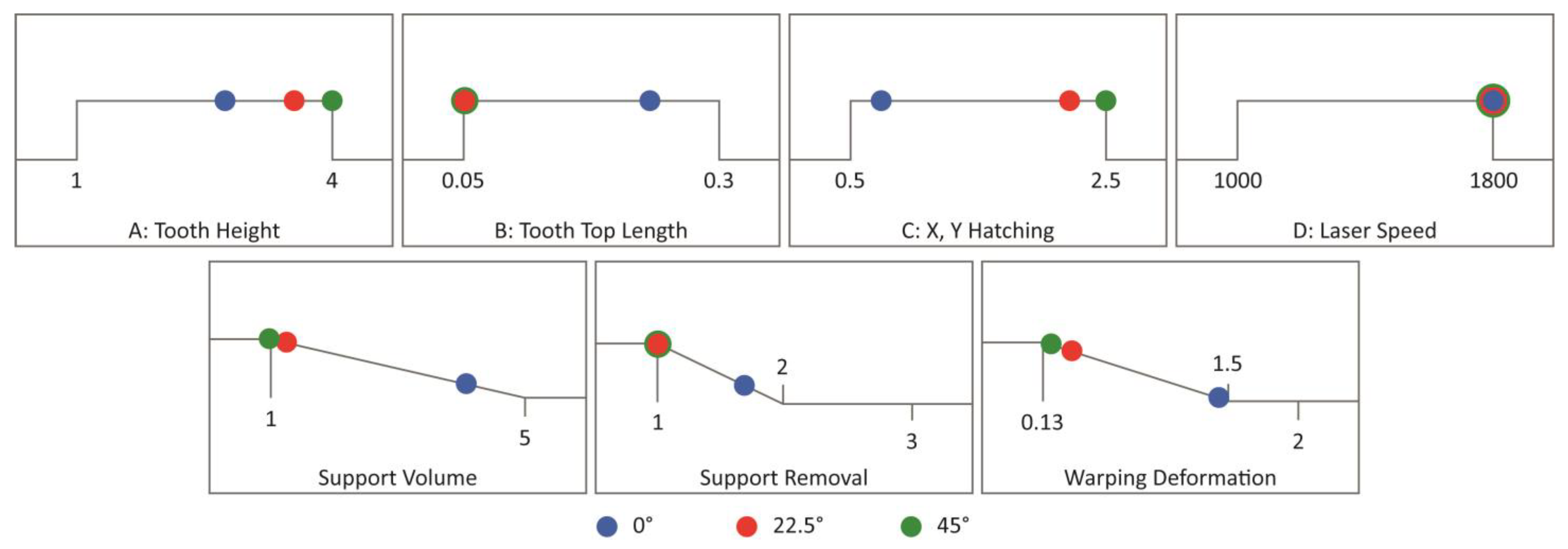
  • For 0° overhangs, the optimal solution was characterized by an average Tooth Height (2.74 mm), large Tooth Top Length (0.23 mm), low X, Y Hatching (0.72 mm), and high Laser Speed (1800 mm/s).
  • For 22.5° overhangs, the optimal solution was characterized by a large Tooth Height (3.56 mm), low Tooth Top Length (0.05 mm), high X, Y Hatching (2.23 mm), and high Laser Speed (1799.9 mm/s).
  • For 45° overhangs, the optimal solution was characterized by a large Tooth Height (4 mm), low Tooth Top Length (0.05 mm), high X, Y Hatching (2.5 mm), and high Laser Speed (1800 mm/s).
Future work will include further research and experimentation on the various support structure parameters, following a similar approach to propose optimized and custom support geometries that minimize the removal effort and material required without having much impact on the quality of the printed part. The scalability of the analysis will be the main objective, investigating and comparing various sizes of overhang surfaces, new materials, and more complex parts. A web application to facilitate independent decision workflows for support design and generation will also be developed, introducing to the industry an innovative tool for effortless, reliable, and sustainable AM.

Author Contributions

Conceptualization, A.D. and I.Z.; methodology, A.D. and I.Z.; software, A.D.; validation, A.D. and I.Z.; formal analysis, A.D.; investigation, A.D. and I.Z.; resources, A.D. and I.Z.; data curation, A.D.; writing—original draft preparation, A.D.; writing—review and editing, I.Z., T.-H.G. and P.C.; visualization, A.D.; supervision, T.-H.G. and P.C.; project administration, T.-H.G. All authors have read and agreed to the published version of the manuscript.

Funding

This publication was made possible by the sponsorship and support of Lloyd’s Register Foundation (LRF). The work was enabled through, and undertaken at, the National Structural Integrity Research Centre (NSIRC), a postgraduate engineering facility for industry-led research into structural integrity, established and managed by TWI Ltd. through a network of both national and international universities.

Data Availability Statement

All data analyzed or generated during the study are included in this article.

Acknowledgments

The author would like to thank and acknowledge Samuel Rosenbaum and Zachy Shtamler from Kanfit3D for providing the equipment and expertise to make the experiments possible, as well as the H2020 KYKLOS 4.0 project for funding the participation of Ilias Zournatzis and the contributions of Kanfit3D.

Conflicts of Interest

The authors declare no conflict of interest.

References

  1. Dilberoglu, U.M.; Gharehpapagh, B.; Yaman, U.; Dolen, M. The Role of Additive Manufacturing in the Era of Industry 4.0. Procedia Manuf. 2017, 11, 545–554. [Google Scholar] [CrossRef]
  2. Haleem, A.; Javaid, M. Additive Manufacturing Applications in Industry 4.0: A Review. J. Ind. Integr. Manag. 2019, 4, 1930001. [Google Scholar] [CrossRef]
  3. Facts & Factors. With 20.50% CAGR, Global Additive Manufacturing Market Size Worth USD 34,846.25 Million by 2028: Additive Manufacturing Industry Trends, Share, Growth, Segmentation, Analysis & Forecast Report. Globe Newswire News Room, 5 September 2022. [Google Scholar]
  4. Chowdhury, S.; Yadaiah, N.; Prakash, C.; Ramakrishna, S.; Dixit, S.; Gupta, L.R.; Buddhi, D. Laser powder bed fusion: A state-of-the-art review of the technology, materials, properties & defects, and numerical modelling. J. Mater. Res. Technol. 2022, 20, 2109–2172. [Google Scholar] [CrossRef]
  5. Gibson, I.; Rosen, D.; Stucker, B.; Khorasani, M. Additive Manufacturing Technologies, 3rd ed.; Chapter 5; Springer International Publishing: Manhattan, NY, USA, 2021. [Google Scholar]
  6. Poyraz, Ö.; Yasa, E.; Akbulut, G.; Orhangül, A.; Pilatin, S. Investigation of Support Structures for Direct Metal Laser Sintering (DMLS) of IN625 Parts; University of Texas at Austin: Austin, TX, USA, 2015. [Google Scholar]
  7. Cheng, B.; Kevin, C. Thermal Stresses Associated with Part Overhang Geometry in Electron Beam Additive Manufacturing: Process Parameter Effects; University of Texas at Austin: Austin, TX, USA, 2014. [Google Scholar]
  8. ISO/ASTM 52911-1:2019. Additive Manufacturing—Design—Part 1: Laser-Based Powder Bed Fusion of Metals. ISO: Geneva, Switzerland, 2019.
  9. Ameen, W.; Al-Ahmari, A.; Mohammed, M.K.; Kaid, H. Multi-objective optimization of support structures for metal additive manufacturing. Int. J. Adv. Manuf. Technol. 2021, 116, 2613–2632. [Google Scholar] [CrossRef]
  10. Ameen, W.; Al-Ahmari, A.; Alkhalefah, H. Design the Support Structures for Easy Removal of Un-Melted Powder in Metal Additive Manufacturing. Int. J. Adv. Sci. Technol. 2020, 29, 1847–1854. [Google Scholar]
  11. Järvinen, J.-P.; Matilainen, V.; Li, X.; Piili, H.; Salminen, A.; Mäkelä, I.; Nyrhilä, O. Characterization of Effect of Support Structures in Laser Additive Manufacturing of Stainless Steel. Phys. Procedia 2014, 56, 72–81. [Google Scholar] [CrossRef]
  12. Hussein, A.; Hao, L.; Yan, C.; Everson, R.; Young, P. Advanced lattice support structures for metal additive manufacturing. J. Mater. Process. Technol. 2013, 213, 1019–1026. [Google Scholar] [CrossRef]
  13. Lindecke, P.N.J.; Blunk, H.; Wenzl, J.-P.; Möller, M.; Emmelmann, C. Optimization of support structures for the laser additive manufacturing of TiAl6V4 parts. Procedia CIRP 2018, 74, 53–58. [Google Scholar] [CrossRef]
  14. Cloots, M.; Spierings, A.B.; Wegener, K. Assessing new support minimizing strategies for the additive manufacturing technology SLM ETH Zurich. In 24th International SFF Symposium; University of Texas at Austin: Austin, TX, USA, 2013. [Google Scholar]
  15. Jhabvala, J.; Boillat, E.; André, C.; Glardon, R. An innovative method to build support structures with a pulsed laser in the selective laser melting process. Int. J. Adv. Manuf. Technol. 2012, 59, 137–142. [Google Scholar] [CrossRef]
  16. Cao, Q.; Bai, Y.; Zhang, J.; Shi, Z.; Fuh, J.Y.H.; Wang, H. Removability of 316L stainless steel cone and block support structures fabricated by Selective Laser Melting (SLM). Mater. Des. 2020, 191, 108691. [Google Scholar] [CrossRef]
  17. Lefky, C.S.; Zucker, B.; Wright, D.; Nassar, A.R.; Simpson, T.W.; Hildreth, O.J. Dissolvable Supports in Powder Bed Fusion-Printed Stainless Steel. 3D Print. Addit. Manuf. 2017, 4, 3–11. [Google Scholar] [CrossRef]
  18. Zeng, K. Optimization of Support Structures for Selective Laser Melting. Ph.D. Thesis, University of Louisville, Louisville, KY, USA, 2015. Available online: https://ir.library.louisville.edu/etd/2221/ (accessed on 1 November 2022).
  19. Jiang, J.; Xu, X.; Stringer, J. Support Structures for Additive Manufacturing: A Review. J. Manuf. Mater. Process. 2018, 2, 64. [Google Scholar] [CrossRef]
  20. Singh, R.; Gupta, A.; Tripathi, O.; Srivastava, S.; Singh, B.; Awasthi, A.; Rajput, S.; Sonia, P.; Singhal, P.; Saxena, K.K. Powder bed fusion process in additive manufacturing: An overview. Mater. Today Proc. 2020, 26, 3058–3070. [Google Scholar] [CrossRef]
  21. Cobbinah, P.V.; Nzeukou, R.A.; Onawale, O.T.; Matizamhuka, W.R. Laser Powder Bed Fusion of Potential Superalloys: A Review. Metals 2020, 11, 58. [Google Scholar] [CrossRef]
Figure 1. Block support structures: (a) Main body; (b) Tooth area; (c) Bottom view.
Jmmp 07 00022 g001
Figure 2. Specimen geometry, supported area, and build direction.
Jmmp 07 00022 g002
Figure 3. Printed outcome.
Jmmp 07 00022 g003
Figure 4. The 3 conditions to evaluate removability.
Jmmp 07 00022 g004
Figure 5. Reference points for evaluating warping deformation.
Jmmp 07 00022 g005
Figure 6. Main plots of Support Volume in Design-Expert 13.
Jmmp 07 00022 g006
Figure 7. Contour plots of support parameters and Overhang Angle on Support Volume.
Jmmp 07 00022 g007
Figure 8. Main plots of Support Removal Effort in Design-Expert 13.
Jmmp 07 00022 g008
Figure 9. Contour plots of support parameters and Overhang Angle on Support Removal Effort.
Jmmp 07 00022 g009
Figure 10. Main plots of Warping Deformation in Design-Expert 13.
Jmmp 07 00022 g010
Figure 11. Contour plots of support parameters, Laser Speed, and Overhang Angle on Warping Deformation.
Jmmp 07 00022 g011
Figure 12. Graphical representation of the selected optimal solutions for 0°, 22.5°, and 45° overhangs.
Jmmp 07 00022 g012
Table 1. Selected support structure parameters and levels.
ParameterLevel 1Level 2Level 3
Tooth Height
Tooth Top Length
X, Y Hatching
Laser Speed
Overhang Angle
1 mm
0.05 mm
0.5 mm
1000 mm/s
2.5 mm
0.175 mm
1.5 mm
1400 mm/s
22.5°
4 mm
0.3 mm
2.5 mm
1800 mm/s
45°
Table 2. Constant parameters.
Tooth Base IntervalTooth Base LengthZ OffsetThicknessFragmentation IntervalSeparation WidthRotation
Angle
0.1 mm1 mm0.06 mm0.2 mm8 mm1 mm45 deg
Table 3. Fit statistics of support volume.
Std. Dev.
Mean
C.V. %
0.0741
2.48
2.99
R2
Adjusted R2
Predicted R2
Adeq Precision
0.9979
0.9972
0.9962
112.346
Table 4. ANOVA results for the quadratic model of Support Volume.
SourceSum of SquaresMean SquareF-Valuep-Value
Model
A-Tooth Height
B-Top Length
C-X, Y Hatching
D-Laser Speed
E-Angle
AB
AC
AD
AE
BC
BD
BE
CD
CE
DE
A2
B2
C2
D2
E2
Residual
Lack of Fit
Pure Error
Cor Total
176.50
0.4288
0.1700
147.65
0.0006
11.20
0.0400
0.0900
0.0025
0.0025
0.1225
0.0000
0.0000
0.0000
4.41
0.0025
0.0057
0.0057
5.60
0.0057
0.1667
0.3793
0.3793
0.0000
176.88
8.82
0.4288
0.1700
147.65
0.0006
11.20
0.0400
0.0900
0.0025
0.0025
0.1225
0.0000
0.0000
0.0000
4.41
0.0025
0.0057
0.0057
5.60
0.0057
0.1667
0.0055
0.0172
0.0000
1605.40
78.01
30.93
26,859.87
0.1070
2037.92
7.28
16.37
0.4548
0.4548
22.29
0.0000
0.0000
0.0000
802.26
0.4548
1.03
1.03
1018.50
1.03
30.33
<0.0001
<0.0001
<0.0001
<0.0001
0.7446
<0.0001
0.0088
0.0001
0.5023
0.5023
<0.0001
1.0000
1.0000
1.0000
<0.0001
0.5023
0.3127
0.3127
<0.0001
0.3127
<0.0001
Table 5. Fit statistics of Support Removal Effort.
Std. Dev.
Mean
C.V. %
0.1838
1.62
11.36
R2
Adjusted R2
Predicted R2
Adeq Precision
0.9669
0.9529
0.9323
22.3995
Table 6. ANOVA results for the quadratic model of Support Removal Effort.
SourceSum of SquaresMean SquareF-Valuep-Value
Model
A-Tooth Height
B-Top Length
C-X, Y Hatching
D-Laser Speed
E-Angle
AB
AC
AD
AE
BC
BD
BE
CD
CE
DE
A2
B2
C2
D2
E2
Residual
Lack of Fit
Pure Error
Cor Total
46.47
0.2439
9.94
0.0000
0.0894
0.3404
0.0762
0.2503
0.0698
0.0052
3.41
0.0766
0.0074
0.1149
0.3472
0.0006
0.8610
0.8610
0.0215
0.0215
0.0858
1.59
1.59
0.0000
48.06
2.32
0.2439
9.94
0.0000
0.0894
0.3404
0.0762
0.2503
0.0698
0.0052
3.41
0.0766
0.0074
0.1149
0.3472
0.0006
0.8610
0.8610
0.0215
0.0215
0.0858
0.0338
0.1444
0.0000
68.75
7.22
294.14
0.0000
2.64
10.07
2.25
7.41
2.06
0.1543
101.04
2.27
0.2177
3.40
10.27
0.0192
25.48
25.48
0.6364
0.6364
2.54
<0.0001
0.0100
<0.0001
1.0000
0.1106
0.0027
0.1399
0.0091
0.1574
0.6962
<0.0001
0.1390
0.6430
0.0715
0.0024
0.8904
<0.0001
<0.0001
0.4290
0.4290
0.1178
Table 7. Fit statistics of Warping Deformation.
Std. Dev.
Mean
C.V. %
0.2876
1.08
26.68
R2
Adjusted R2
Predicted R2
Adeq Precision
0.8503
0.8069
0.7403
14.2794
Table 8. ANOVA results for the quadratic model of Warping Deformation.
SourceSum of SquaresMean SquareF-Valuep-Value
Model
A-Tooth Height
B-Top Length
C-X, Y Hatching
D-Laser Speed
E-Angle
AB
AC
AD
AE
BC
BD
BE
CD
CE
DE
A2
B2
C2
D2
E2
Residual
Lack of Fit
Pure Error
Cor Total
32.40
0.0861
0.0005
0.0124
0.0076
17.22
0.0049
0.0182
0.1444
0.4225
1.20
0.0025
0.6084
0.0132
2.81
0.0169
0.0232
0.0130
0.0142
0.0106
2.76
5.71
5.71
0.0000
38.11
1.62
0.0861
0.0005
0.0124
0.0076
17.22
0.0049
0.0182
0.1444
0.4225
1.20
0.0025
0.6084
0.0132
2.81
0.0169
0.0232
0.0130
0.0142
0.0106
2.76
0.0827
0.2594
0.0000
19.59
1.04
0.0058
0.1505
0.0922
208.23
0.0592
0.2204
1.75
5.11
14.50
0.0302
7.36
0.1599
33.92
0.2044
0.2809
0.1570
0.1716
0.1279
33.39
<0.0001
0.3111
0.9397
0.6992
0.7623
<0.0001
0.8084
0.6402
0.1907
0.0270
0.0003
0.8625
0.0084
0.6905
<0.0001
0.6526
0.5978
0.6932
0.6800
0.7217
<0.0001
Table 9. Criteria constraints.
NameGoalLower LimitUpper Limit
A: Tooth Height
B: Tooth Top Length
C: X, Y Hatching
D: Laser Speed
Support Volume
Support Removal
Warping Deformation
in range
in range
in range
in range
minimize
minimize
minimize
1 mm
0.05 mm
0.5 mm
1000 mm/s
1 (normalised)
Condition 1
0.13 mm
4 mm
0.3 mm
2.5 mm
1800 mm/s
5 (normalised)
Condition 2
1.5 mm
Table 10. Optimum results of 0°, 22.5°, and 45° overhangs.
Angle.Tooth HeightTooth Top LengthX, Y HatchingLaser SpeedSupport VolumeSupport RemovalWarping
Deform.
Desirability

22.5°
45°
2.738
3.557
4.000
0.230
0.050
0.050
0.722
2.227
2.500
1800
1799.9
1800
4.074
1.216
1.000
1.700
1.000
1.000
1.437
0.313
0.195
0.147
0.936
0.984
Disclaimer/Publisher’s Note: The statements, opinions and data contained in all publications are solely those of the individual author(s) and contributor(s) and not of MDPI and/or the editor(s). MDPI and/or the editor(s) disclaim responsibility for any injury to people or property resulting from any ideas, methods, instructions or products referred to in the content.

