Article

Three-Body Abrasive Wear-Resistance Characteristics of a 27Cr-Based 3V-3Mo-3W-3Co Multicomponent White Cast Iron with Different Ti Additions

by
Riki Hendra Purba
1,2,
Kazumichi Shimizu
1 and
Kenta Kusumoto
1,*
1
Mechanical Engineering Department, Muroran Institute of Technology, 27-1 Mizumoto, Muroran City 050-8585, Japan
2
Department of Mechanical Engineering, University of Sumatera Utara, Medan 20155, Indonesia
*
Author to whom correspondence should be addressed.
J. Manuf. Mater. Process. 2023, 7(1), 21; https://doi.org/10.3390/jmmp7010021
Submission received: 30 November 2022 / Revised: 6 January 2023 / Accepted: 9 January 2023 / Published: 10 January 2023

Abstract

:
A multicomponent white cast iron containing 5 wt.% each of Cr, V, Mo, W, and Co (MWCI) is known to have excellent wear-resistance properties due to the precipitation of some very hard carbides, such as MC, M2C, and M7C3. However, it seems possible to improve the wear resistance of MWCI by increasing the carbide volume fraction (CVF). Thus, 27 wt.% Cr based on 3 wt.% each of V, W, Mo, and Co was simultaneously added into the white cast iron. To avoid the tendency of carbides to crack due to high M7C3 precipitation levels, titanium (0–2 wt.% Ti) was also added. A rubber wheel abrasive machine test according to the ASTM G65 standard with two different abrasive particle sizes (average: 75 and 300 μm) was used to evaluate the wear characteristics of the alloy. The results show that the wear resistance of these new alloys (0Ti, 1Ti, and 2Ti) is lower than that of MWCI in small silica sand, owing to the lower hardness. However, a different condition is present in large silica sand, for which the abrasive wear resistance of MWCI is lower than that of the 0Ti and 1Ti specimens. In addition, TiC precipitation effectively refined the size of M7C3 carbides and reduced their cracking tendency. Thus, the wear resistance of 1Ti is comparable to that of 0Ti, although it has a lower hardness factor. However, the wear resistance of the alloy significantly decreased following the addition of Ti by more than 1 wt.% due to the lower hardness and CVF. Therefore, it can be said that the abrasive wear characteristics of the alloy are not only affected by the hardness, but also by the micro-structural constituents (type, size, and volume fraction of carbides) and silica sand size.

1. Introduction

It has been reported in the literature that a company’s production costs would significantly increase due to the detrimental effects of wear phenomena on material surfaces [1]. In particular, Holmberg et al. [2] stated that this could cost about EUR 210,000 million and generate about 970 million tons of CO2 emissions annually. This fact has encouraged many researchers to discover materials with excellent wear-resistance properties. Based on the mechanism, wear can be categorized into several groups, such as abrasive, erosive, adhesive, fritting, and corrosive, where the greatest contributor to material failure due to wear phenomena is abrasive wear, especially in three-body conditions [3,4,5]. Three-body abrasive wear can be defined as the progressive loss of material due to hard particles being forced and moving along a solid surface [3]. It can be found in various parts of machinery or engineering applications [4,6]. For example, when an iron ore is delivered from the field stock to the blast furnace feeder in the steelmaking process, it would often abrade the surface transportation equipment. Since this equipment is one of the vital parts in the steelmaking process, it is very important to maintain the service life of this material. However, it is expected that the material development in this research can also be applied to other machine parts, such as metal crushers, excavator gears and wheels, and bulldozers [3].
High-chromium white cast iron (HCCI) containing 2–4 wt.% C and 16–30 wt.% Cr has been applied under high-severity-wear conditions due to the better hardness and precipitation qualities of Cr carbides, especially the M7C3 type. It has been revealed that a higher CVF in the microstructure has better wear-resistance properties [4,5,6]. However, the precipitation of these carbides causes brittleness due to their high hardness, which limits its applications. This means that the microstructure plays as important role in determining the wear behavior of material [7]. Numerous studies have been diligently conducted by previous experts, for example, by modifying M7C3 carbides’ orientation (transverse or longitudinal) and size and increasing the hardness of the matrix. Coronado [8] revealed that modifying the orientation of M7C3 through adjusting the cooling rate of molten iron during the solidification process can improve the toughness of the carbide and provide a considerable improvement to its abrasive wear-resistance property. However, the application of this method is very difficult to control and has not yet met the standards of the research at present. Another option is to refine the size of M7C3 carbides by adding stronger transition metals, such as Ti, Nb, V, and W [9,10,11,12]. Wang et al. [13] determined that Ti has a stronger driving force for carbide formation because it has a higher affinity with C than other elements. This suggests that TiC carbides are expected to precipitate more favorably from the molten iron than NbC or VC, even under rapid cooling conditions [12,13]. In addition, as one of the carbide-forming elements commonly used in HCCI, Ti forms TiC with a hardness value exceeding 3200 HV [14], much higher than M7C3 (1200–1800 HV) [8,15,16], thus resulting in an appropriate solution to the wear problem. Regarding the formation process, Zhu et al. [17] stated that Ti powder would react with C in the melt and form TiC carbides in situ due to the high affinity of Ti with C and simultaneously refine the size of M7C3 carbides. Zhou et al. [18] also obtained similar results which the precipitation of TiC on the mi-crostructure of hypereutectic Fe-Cr-C can effectively reduce the size of M7C3 carbides providing in better wear-resistance properties. However, Ibrahim et al. [19] and Chung et al. [20] observed that the opposite condition would occur after the quantity of Ti ex-ceeded 2 wt.% due to the lower CVF and toughness of HCCI. Thus, although the pres-ence of TiC carbide could significantly increase the hardness of the material, its addition would not be more than 2 wt.% to avoid reducing wear resistance in this study.
Another method to improve the wear resistance of white cast iron by adding some transition metals, such as such as Cr, Mo, W, V, and Co, called multicomponent white cast iron (MWCI), was conducted in recent decades. The results show that MWCI has higher wear-resistance properties than HCCI at both room and high temperatures. This is due to the increased of precipitated carbide types, such as MC, M2C, and M23C6, in the microstructure during solidification and heat-treatment processes. The letter M represents the added transition metal. The MWCI was applied to some machine components, such as roll mills, pulverizing, and the rotating chute liner of a blast furnace [21,22,23,24,25]. However, Kusumoto et al. [22,25] noticed that the CVF of MWCI (about 18–22%) was lower than that of HCCI (approximately 27–33%) because only approximately 5 wt.% of each transition metal was added to the white cast iron. This result shows that it remains possible to improve the wear resistance of MWCI by increasing the amount of Cr to 27 wt.%. In addition, the effect of Ti on MWCI has not been studied in the literature, which results in a lack of information. In other words, it is important to analyze the wear performance of the combination of HCCI and MWCI with the addition of Ti to obtain a more detailed explanation. However, as more Cr and Ti are added, it is important to reduce the amount of other components from 5 wt.% to 3 wt.% of V, Mo, W, and Co to prevent brittleness without hindering the possibility of MC and M2C carbide formations.
Based on the abovementioned results, the purpose of this study is to investigate the three-body abrasive performance of white cast iron with the simultaneous addition of 0–2 wt.% Ti and 27 wt.% Cr based on 3 wt.% of V, Mo, W, and Co, hereafter expressed as 0Ti, 1T1, and 2Ti. Additionally, this is compared with MWCI to determine the improvement of this new alloy. It is expected to provide a better solution for high production costs and CO2 emissions due to wear problems and enrich the theoretical knowledge of the effects of Ti addition on 27Cr-based MWCI.

2. Materials and Methods

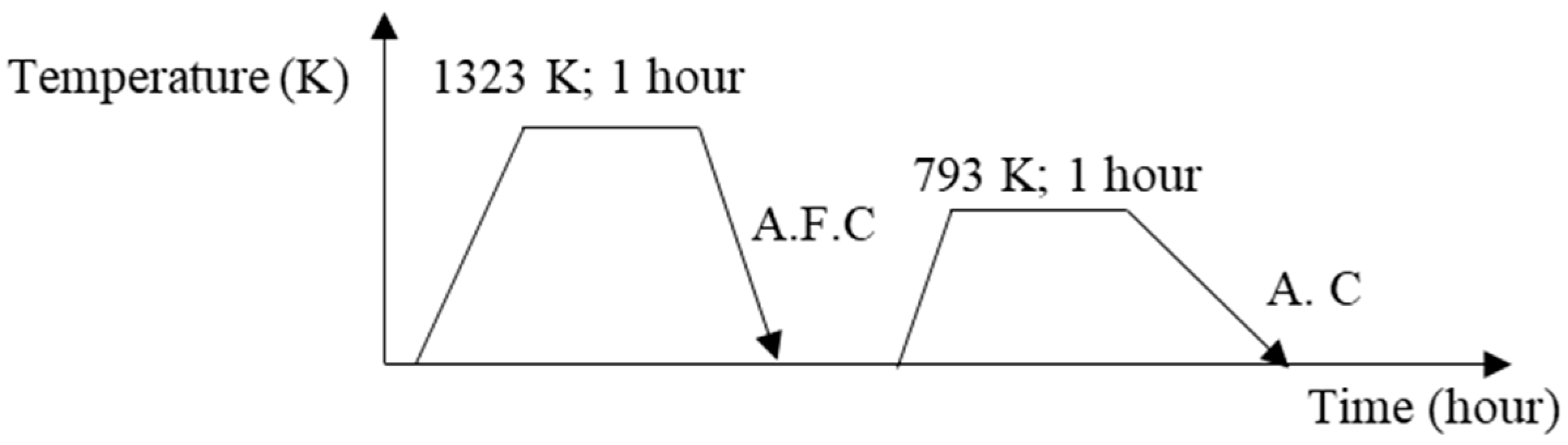
2.1. Material Preparation

In this study, ferroalloys were pre-designed with 0; 1; and 2 wt.% Ti at 27 wt.% Cr based on 3 wt.% of V, Mo, W, and Co. MWCI containing 5% of each of Cr, V, Mo, and W, and Co was used as a comparison material. Approximately 50 kg of raw materials were melted using a high-induction furnace at the normal atmospheric pressure of 1 atm, then poured into a sand mold with dimensions of 53 mm × 250 mm × 15 mm. Subsequently, ingot materials were cut into dimensions of 50 mm × 10 mm × 10 mm using a high-speed precision-cutting machine (Refinetech Co., Ltd., RCA-234, Kanagawa, Japan). Liquid was flowed as a coolant inside the machine to avoid microstructure changes due to friction phenomena occurring during the cutting process. In addition, the composition of each alloy after solidification was measured using SPEC-TROLAB (AMETEK, Inc., Berwyn, PA, USA) and the results are presented in Table 1.
In the previous studies [22,25,26,27,28], it was suggested that the wear-resistance properties of HCCI and MWCI following the destabilization heat-treatment process was higher than that of the as-cast condition due to the transformation of the austenite matrix into martensite and the precipitation of secondary carbides. Generally, the alloy would first be quenched by air cooling following heating at 1173–1423 K for one hour, and followed by tempering by air cooling following heating at 693–813 K for one hour [29,30]. Therefore, all specimens were firstly quenched by heating at 1323 K and kept for one hour, and then, the temperature was decreased by the air-forced cooling (A.F.C) method using a fan (cooling rate was about 2.5 K/s). Then, this was followed by the tempering process after heating at 793 K for one hour; then, it was cooled by the air-cooling method (A.C). In addition, the heating rate from room temperature to 1323 K (quenching) or 793 K (tempering) was about 0.11 K/s. The schematic of the destabilization heat-treatment process is presented in Figure 1. After the heat treatment process was conducted, all specimen surfaces were uniformed using a grinding machine (GS52PF; Kuroda Seiko Co., Ltd., Kanagawa, Japan). The machine was firstly set to automatically the obtain roughness (Ra) of each specimen of approximately 0.21 µm.

2.2. Metallographic Analysis and Hardness Measurement

To analyze the microstructure of each specimen, samples with dimensions of 10 × 10 × 10 mm were first prepared and polished with silica sandpaper and diamond suspension. The polishing stage was initiated by using silica sandpaper from 120 P, 400 P, 600 P, and 1200 P. Then, we proceeded with diamond suspensions at 9, 3, and finally 1 μm. Then, the samples were etched for approximately 4–6 min in a hydrochloric acid solution at room temperature and observed using an optical microscope (OM; Eclipse LV150N, Nikon, Tokyo, Japan). The hydrochloric acid solutions used in this study were HCl (35–37%) and HNO3 (69–70%) at a ratio of 3:1. Meanwhile, scanning electron microscopy (SEM + EDS; JSM-6510A, JEOL, Tokyo, Japan) with an accelerating voltage of 20 kV, wave length dispersive (9–20 mm), factory pre-centered filament, electrical image: shift ± 50 μm, specimen stage: eucentric large-specimen stage, X: 80 mm, Y: 40 mm, Z: 5 mm to 48 mm, was used to determine the type of carbides and the distribution of each added element. The chemical analysis of each carbide was measured by the EDS. X-ray diffraction (XRD, Ultima VI Pro, Rigaku, Japan) was conducted by a Cu tube, with a tube voltage of 40 kV and tube current of 20 mA. The range of 2θ was 30–90 deg. A test piece attached to the sample stage was irradiated with an X-ray beam of 0.3 × 5 mm. The PDXL2 database was used to identify the phases of the specimen’s microstructure. The CVF and carbide size and the total CVF were calculated using the binarizing image-processing technique in ImageJ at five different SEM-EDS locations. The carbide type was determined through the technique of point analysis on 5 SEM-EDS mappings with more than 20 repetitions of the test being performed. Future-Tech Co. Ltd.: FV-800, Kanagawa, Japan Vickers hardness testers were used to measure the hardness property of the material (weight 294 N). Measurement data were obtained with 12 repetitions of the test.

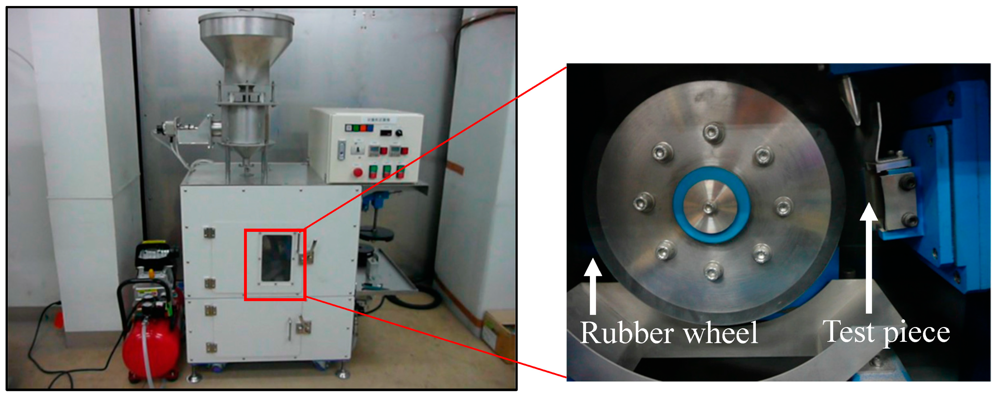
2.3. Three-Body Abrasive Wear Test

A rubber wheel wear machine according to ASTM G65 was used to evaluate three abrasive wear behaviors of materials with specimen dimensions of approx. 50 mm × 10 mm × 10 mm at a load of 368 N. The total sliding distance was approximately 430 m, the sliding speed was 1.2 m/s, and the time was 6 min. This study also evaluated the size effect of silica sand as an abrasive particle. Thus, silica sands (97.99% SiO2) (approximately 75 and 300 µm of the average) with the same hardness value of 1100 HV were supplied at approximately 4.2 g/s from the hopper in between the rubber and the specimens. The test was conducted at room temperature, with a normal atmospheric pressure of 1 atm, and the average humidity was 75–85%. The machine tests and SiO2 are presented in Figure 2 and Figure 3. Each test was repeated six times and the average of the results was used. To calculate the wear rate of each material, the following equation was used:
Wear   rate   = Δ m π dtn
where ∆m is the material weight loss (kg), d is the diameter of the wheel (m), t is the time (s), and n is the rotating speed (rpm).
The wear surface and cross-section of the specimen following testing would also be observed to determine the abrasive wear mechanism. The specimens were first cut using a fine cutter on the most abrasive areas with dimensions of 10 × 10 × 10 mm and embedded in epoxy resin. It was polished using silica paper and diamond suspension paste for a cross-section investigation, for which the step of polishing was the same as that described in Section 2.2.

3. Results and Discussion

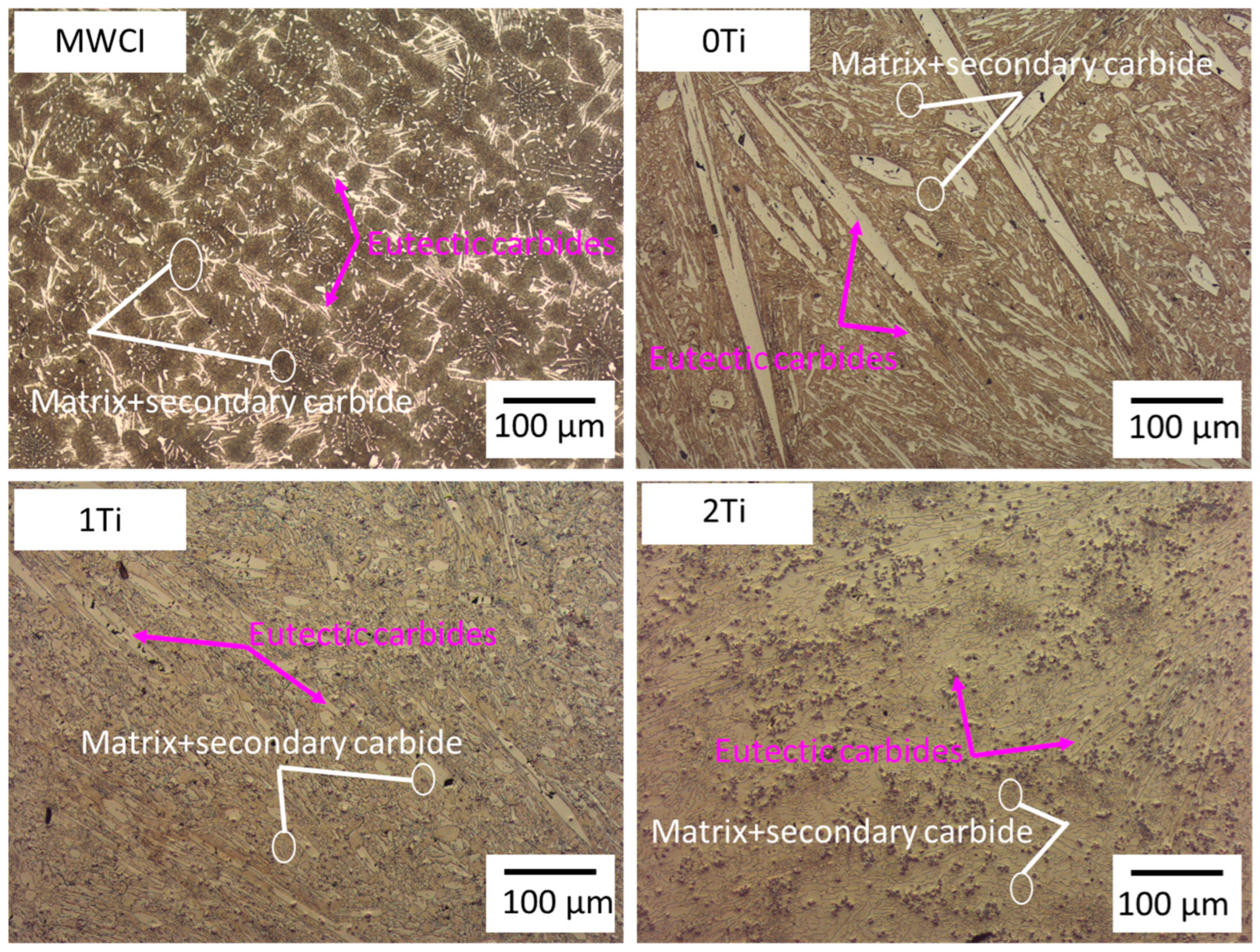
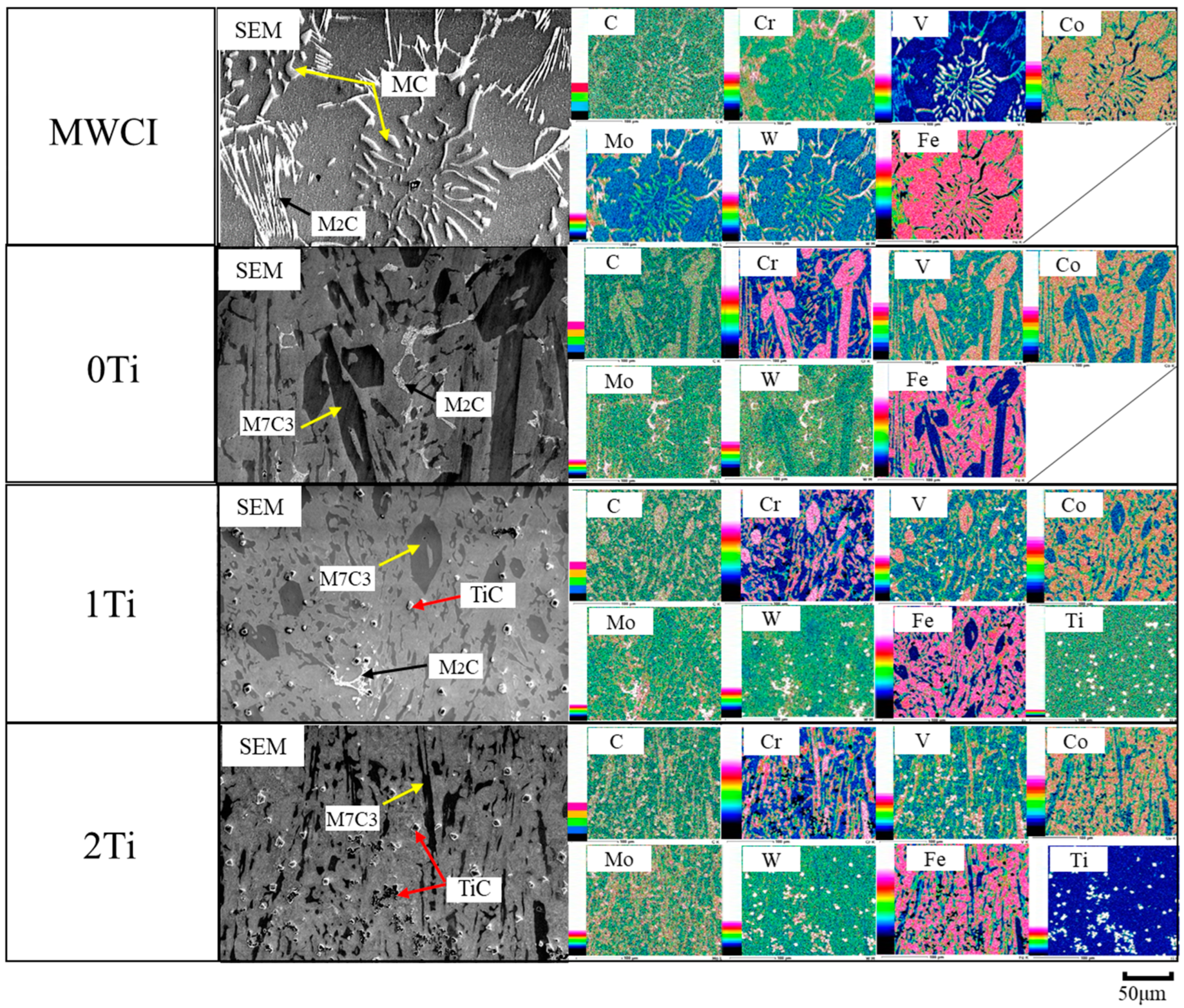
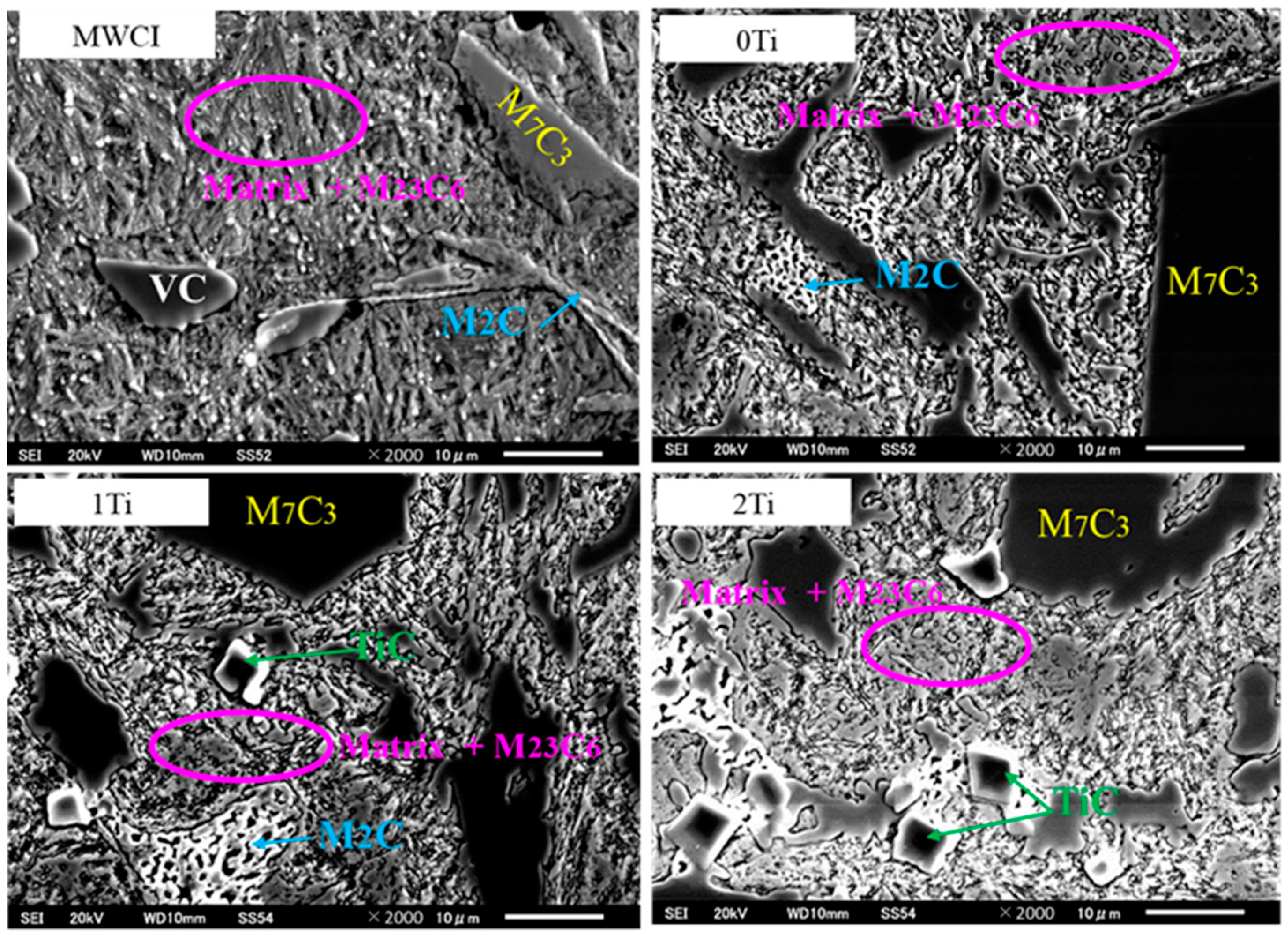
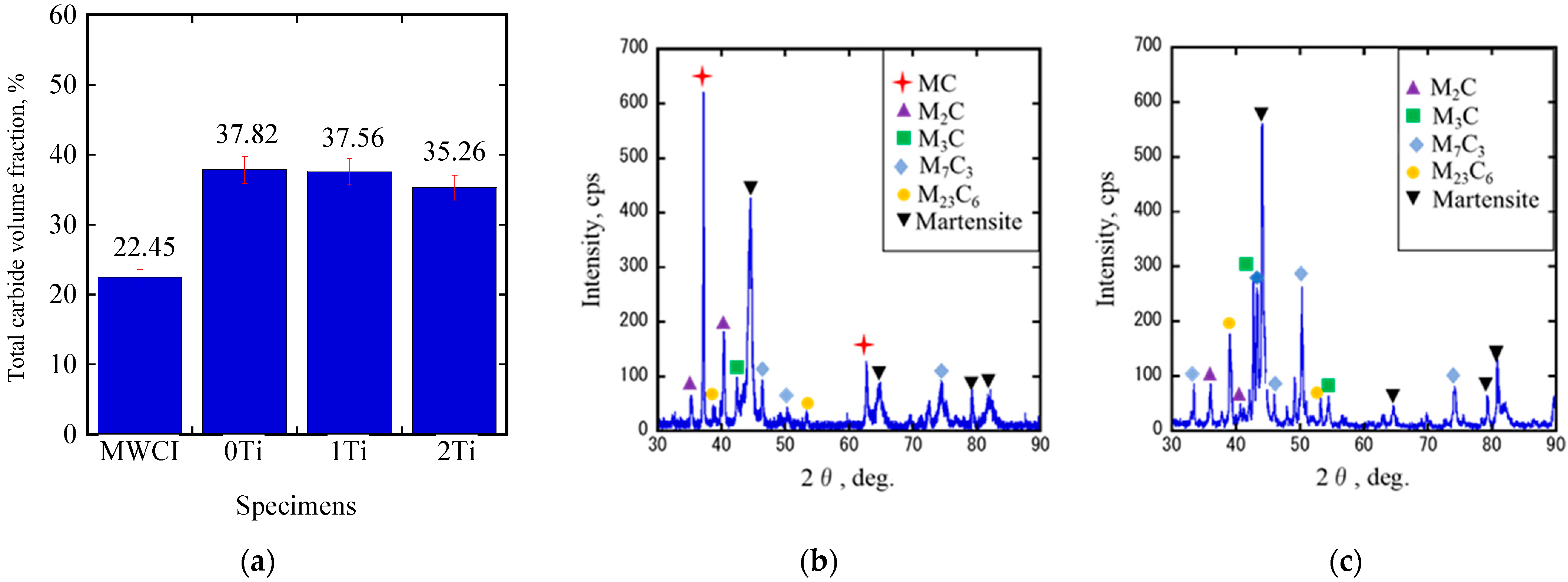
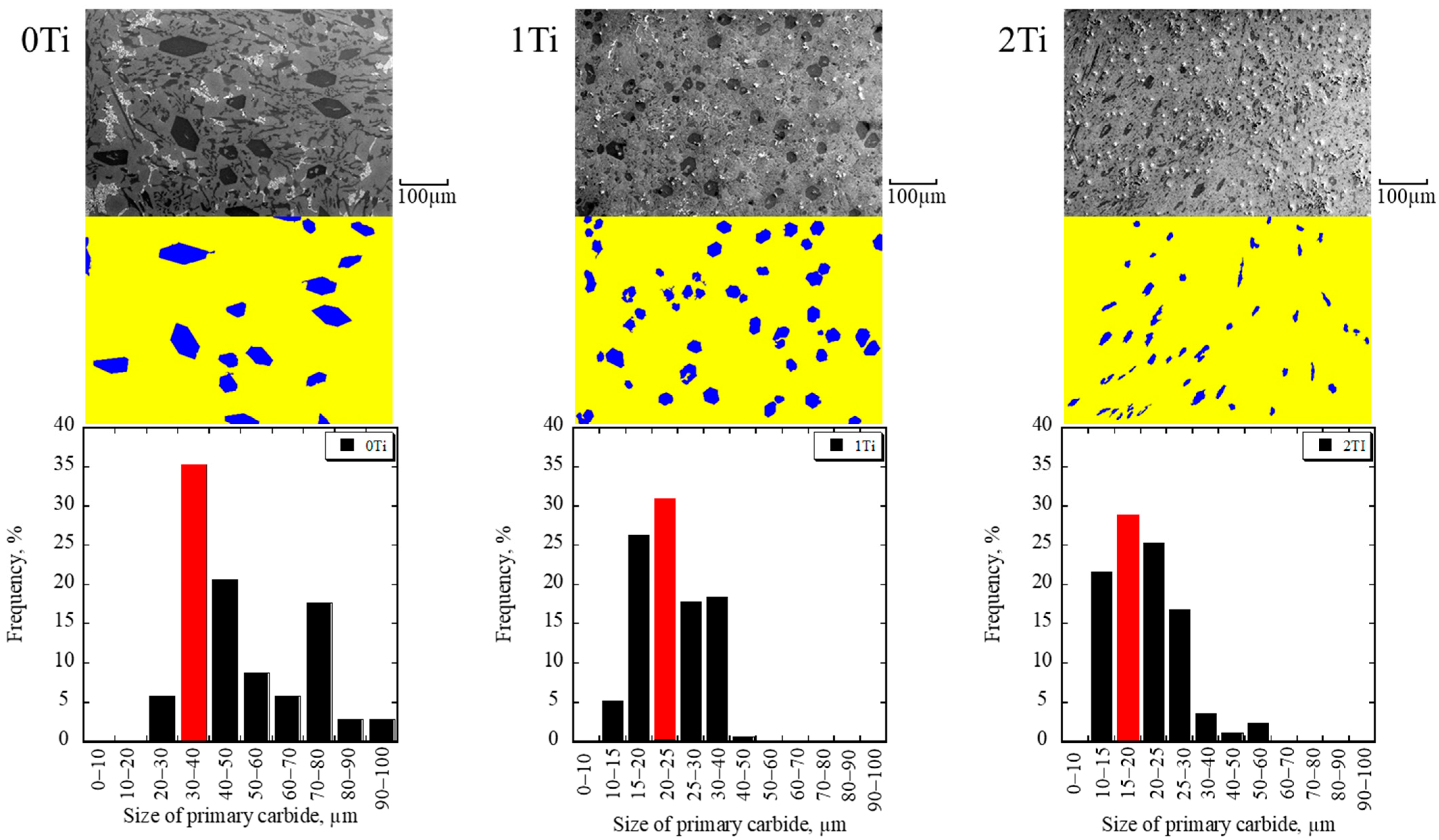
3.1. Microstructure Analysis

As previously described, the microstructure of the materials plays an important role in the evaluation of their wear behavior [7]. Therefore, the microstructure of each tested material was first observed through an optical microscope (OM) after being etched with a hydrochloric acid solution for 4 to 6 min. It can be observed that the microstructure contains a matrix with fine secondary carbides and plural precipitated carbides, as presented in Figure 4. The matrix is represented by a dark-brown color and no significant differences can be observed between MWCI and 0Ti, 1Ti, 2Ti. Meanwhile, carbide precipitation is represented by the brighter areas. In addition, carbides in the microstructure of MWCI appear globular and fiber-like, while hexagonal shapes appear as the main carbides and fine globulars in the case of 0Ti, 1Ti, and 2Ti, as described in Table 2. However, it is very difficult to determine the type of carbide from this perspective. Additionally, the distribution of each added transition metal cannot be determined from these results. Therefore, the evaluation was continued using SEM-EDS as well as XRD machines to obtain more accurate information. The SEM-EDS results can be observed in Figure 5.
Figure 5 presents the precipitation of MC carbides with globular-like shapes and M2C carbides with fiber-like shapes in the microstructure of MWCI. The letter M in MC carbide is mostly occupied by element V. Additionally, the M2C carbide is occupied by W and Mo elements. The presence of Cr carbides as M7C3 is very difficult to observe from this viewpoint, which may be due to the small CVF. This result is in agreement with our previous studies [22,25]. In the case of 0Ti, the crystallization of M2C and M7C3 carbides can be observed. Similar to the MWCI case, W and Mo are embedded as M2C carbides [22,30], whereas M7C3 carbides are mostly occupied by Cr and V elements and have a hexagonal shape. VC precipitation cannot be observed, as reported in some previous studies [25,31]. Then, MC precipitation as a TiC carbide can be clearly observed in the microstructures of 1Ti and 2Ti, where the amount of this carbide increases as the amount of Ti addition increases. However, M2C seems to decrease at a 1 wt.% Ti addition and disappears with a 2 wt.% Ti. In addition, the results show that the M7C3 carbide becomes finer as the amount of Ti increases. With the greater magnification performed by SEM, it can be observed that the matrix of each specimen appears to be needle-like in shape, which indicates that martensite is the main matrix type in the microstructure, as presented in Figure 6. XRD was used to gain a more detailed explanation, as described later. In addition, there are numerous fine carbides present, as M23C6 is observed inside the matrix area.
Table 2. Characteristics of precipitated carbides.
AlloyCarbide TypeCarbide CompoundShapeCrystal StructureHardness
[14,30,32]
MWCIMC(Fe0.57V0.43)C1.01GlobularFCC2800 HV
M2C(Fe1.10Mo0.40W0.50)C1.05Fiber-likeHexagonal2300 HV
M7C3-Fiber-like-1600 HV
M23C6(Fe18.40Cr3.01V0.30Mo1.00W0.30)C6.07Fine-globularFCC1000 HV
0TiMC----
M2C(Fe1.17Mo0.38W0.45)C1.00Fishbone-likeHexagonal2300 HV
M7C3(Fe2.90Cr3.50V0.60)C3.01Hexagonal rod-like/plateHexagonal1600–1800 HV
M23C6(Fe18.34Cr3.11V0.50Mo1.00W0.05)C6.14Fine-globularFCC1000 HV
1TiMC(Fe0.29Ti0.71)C1.03DiamondFCC3200 HV
M2C(Fe1.33Mo0.21W0.46)C1.04Fishbone-likeHexagonal2300 HV
M7C3(Fe3.34Cr3.40V0.20)C2.87Hexagonal rod-like/plateHexagonal1600–1800 HV
M23C6(Fe20.09Cr2.00V0.54Mo0.25W0.12)C6.01Fine-globularFCC1000 HV
2TiMC(Fe0.23Ti0.73V0.01Mo0.01W0.02)C0.95DiamondFCC3200 HV
M2C----
M7C3(Fe4.27Cr2.72V0.01)C3.00Hexagonal rod-like/plateHexagonal1600–1800 HV
M23C6(Fe20.45Cr2.18V0.31Mo0.03W0.03)C5.88Fine-globularFCC1000 HV
To obtain more comprehensive data, the CVF was calculated and the results are presented in the bar chart in Figure 7a. The results show that MWCI has a lower CVF compared to 0Ti, 1Ti, and 2Ti. It can be understood that as more Cr is added to white cast iron, more CVF, especially the M7C3 carbide type, is precipitated in the microstructure due to the micro-segregation phenomenon occurring in the molten iron during the solidification process. However, the CVF decreases as the amount of Ti addition increases. In the previous studies [17,21,30], it was shown that TiC would first crystallize in the iron melt, followed by the formation of M7C3 carbide, and then by the formation of M2C carbides. This means that increased Ti additions would naturally consume a higher C content during the first stage, resulting in a lower C concentration. Then, when the iron melt attains the formation temperature of the M7C3 carbide, the smaller M7C3 carbide would be formed by Cr. Additionally, in the final step, the lower CVF of M2C would be precipitated by W and Mo elements in 1Ti, and would even disappear in the 2Ti specimens. Thus, the highest CVF was observed for 0Ti, and the lowest for MWCI.
Based on the XRD data of the representative materials, as presented in Figure 7b,c, consistent results were also obtained. It can be observed that the microstructures of both materials contain various carbides stoichiometries. Since the C atom has a high affinity with all the added transition metals, it allows for the crystallization of these carbides to occur. It also reveals that only the martensite phase of the matrix is indexed in MWCI and 0Ti. Meanwhile, the retained austenite phase, as reported in the previous studies [33,34,35] (HCCI and MWCI samples), was not observed in this study. This result may have been caused by two factors, such as the differences in the overall chemical composition and differences in the destabilization heat-treatment process (cooling rate and heating temperature) [26,30]. Therefore, it can be firmly stated that the difference in the overall chemical composition of the alloy also plays a key role in the type of carbides and matrix present in the microstructure of a material.
The sizes of the primary M7C3 carbides in the microstructures of 0Ti, 1Ti, and 2Ti were measured and the results are presented in the bar chart in Figure 8. However, the size of the M7C3 carbides in the case of MWCI was difficult to measure, which may have been due to the low addition of Cr (only 5 wt%). It can clearly be observed that the average size of primary M7C3 carbides significantly decreases as the amount of Ti increases, due to the lower negative enthalpy mixing of Ti-C (−84.52 kJ/mole) than of Cr-C (−14.98 kJ/mole) [12]. From this result, it can be observed that a higher quantity of transition metals added into the white cast iron does not necessarily guarantee a higher CVF and increased carbide types. However, this was also considerably influenced by the C concentration in the microstructure of each material. To determine the effect of all these microstructure conditions on the hardness property and wear behavior of the material, Vickers hardness measurements and abrasive wear tests were conducted, as discussed in the subsequent section.

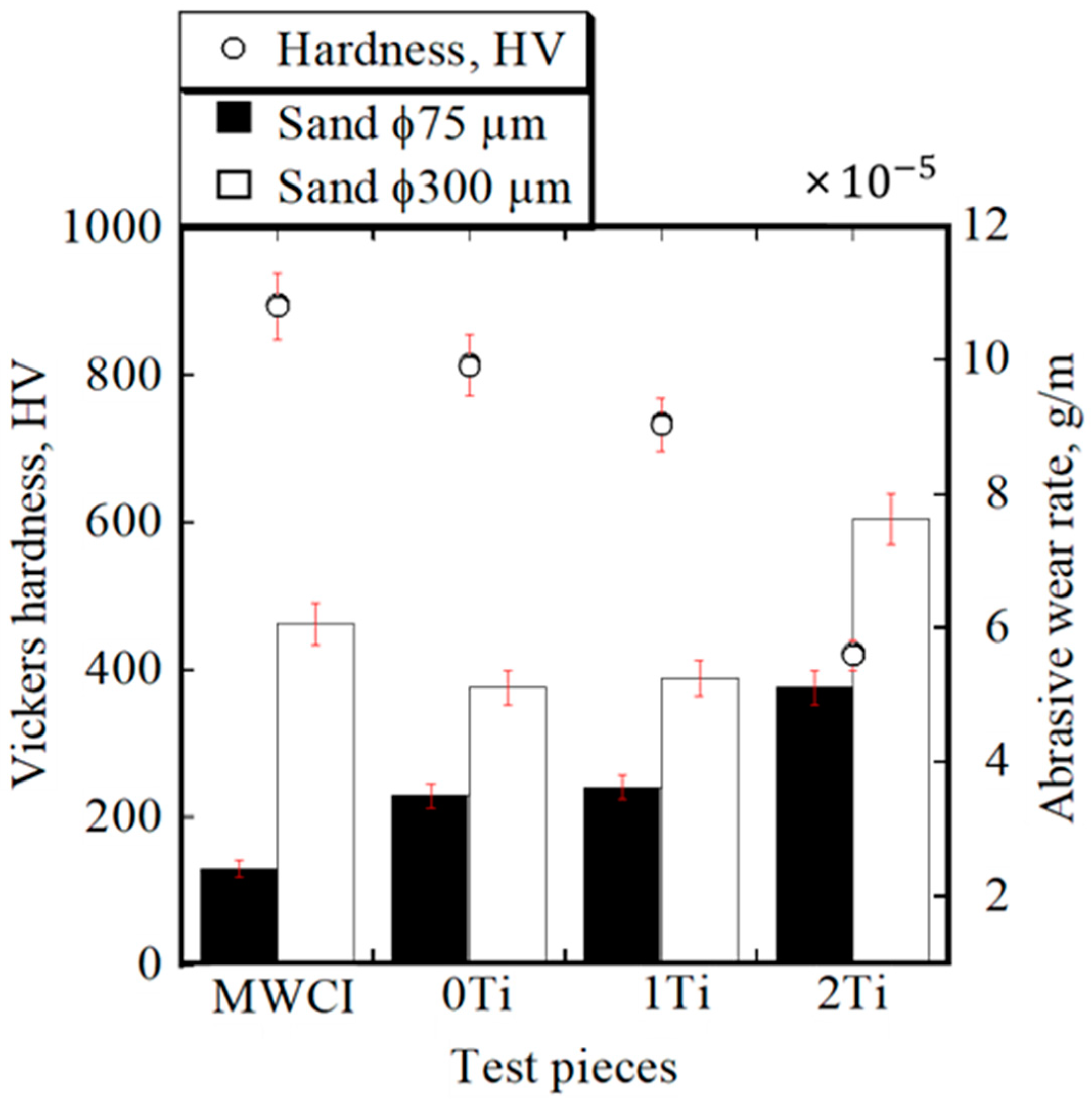
3.2. Vickers Hardness of Materials and Abrasive Wear Behavior

The relationship between material hardness and abrasive wear rate is presented in Figure 9. It can be observed that the hardness level of MWCI (approximately 870 HV) is greater than that of 0Ti (approximately 805 HV) despite having lower CVF. Besides that, even though the amount of TiC carbide increased as the Ti addition was increased, the hardness of the high-Cr-based multicomponent white cast iron decreased slightly with the addition of 1 wt.% Ti and then decreases dramatically with the addition of 2 wt.% Ti. It means the reduction in the material’s hardness was not consistent with the increase in the amount of transition-metal addition or CVF, which is a result that differs to that published in older articles [19,20,21,24]. As previously explained, the more transition metals added to white cast iron, the greater the formation of eutectic carbides in the microstructure during the solidification process. This is evidenced by the higher amount of CVFs present in the microstructures of 0Ti, 1Ti, and 2Ti specimens. Therefore, the amount of C solubility in the matrix decreases, which leads to the reduction in material hardness. In addition, the absence of M2C carbides in the microstructure of the 2Ti sample due to the less available C solubility may dramatically reduce the hardness of the material compared to 0Ti. Therefore, it can be determined that a higher CVF in the microstructure does not necessarily result in a material with greater hardness properties. Moreover, the presence of TiC would also reduce the hardness of the material studied in the present paper due to the depletion of C concentration in the matrix, which is quite different from the results presented in the previous studies [19,20].
Figure 9 also exhibits the abrasive wear rate of each material with different silica sand sizes. This shows that all specimens experience the same conditions where larger silica sand causes greater material loss. It can be understood that the larger silica sand detached a wider the materials surface area during the test. Thus, the wear rate of the same material condition (same CVF, type of carbide and matrix, and hardness) increases as increase the size of silica sand. This fact is consistent with the conclusions found in previously published papers [36,37]. In the case of small silica sand, it can be observed that MWCI has a lower abrasive wear rate compared to 0Ti, 1Ti, and 2Ti specimens. This can be understood due to the higher hardness property of MWCI compared to the others. However, the hardness of the material is not consistent when comparing 0Ti and 2Ti. Although 0Ti has a higher hardness value, there is no significant difference present, nor can it be said to have comparable values with the addition of 1Ti. It is also not possible to determine the reason for this outcome from the CVF perspective, where 0Ti has a higher CVF than 1Ti. This means that material hardness, as well as CVF, do not always act as good indicators for understanding the wear behavior of materials with small silica sand (SiO2). Additionally, this is definitely influenced by other factors that are discussed in the subsequent section. However, it can be determined that the best abrasive wear resistance characteristic belongs to MWCI (wear rate: approximately 2.42 × 10⁻⁵ g/m). Meanwhile, 2Ti (wear rate: approximately 5.12 × 10⁻⁵ g/m) has the lowest abrasive wear resistance rate among all specimens with small silica sand.
Unlike for small silica sand, the wear rate of MWCI is higher than that of the 0Ti and 1Ti specimens for the large silica sand test. However, the wear rate of MWCI is lower than that of the 2Ti specimen. Nevertheless, there is no significant wear rate evident between 0Ti and 1Ti; similar to the small silica sand test. The reason for this result is also difficult to determine from the material hardness or CVF. The comparable wear-resistance rate between 0Ti and 1Ti during both small and large silica sand testing can be assumed to be due to the refinement of M7C3 carbides as an effect of Ti addition, as previously described (Section 3.1). The refinement of the M7C3 carbide may reduce the tendency of the carbide-cracking phenomenon during abrasive wear testing. However, although they have same type of matrix as martesite, the lower hardness, as well as the lower CVF of M7C3 and M2C of 1Ti than of 0Ti as the crystallization effect of TiC resulted in the matrix of 1Ti being more easily abraded by the larger silica sand. Eventually, it produced an abrasive wear resistance quite similar to that of the 0Ti specimen, despite presenting a better toughness characteristic of the M7C3 carbide and TiC precipitation in the microstructure. In addition, it can also be observed that even though the amount of TiC was higher in the 2Ti specimen, it did not produce better wear resistance. This means that the wear resistance of the material would be considerably reduced once the amount of Ti exceeded the threshold (1 wt.% Ti) in this study. This condition is quite different with previous studies. Ibrahim et al. [19] and Chung et al. [20] said that the wear resistance of HCCI would decrease once the addition of Ti was 2 wt.% due to high hardness or too brittle. Meanwhile, the wear resistance of the present material (more than 1 wt.% Ti) decreased due to a significant decrease in hardness. To obtain a clear explanation for this result, the investigation was continued by observing the abrasive wear mechanism as described in the subsequent section. Nevertheless, it can be observed that the materials with the best abrasive wear resistance properties during large silica sand testing were 0Ti (wear rate: approximately 5.12 × 10⁻⁵ g/m) and 1Ti (wear rate: approximately 5.26 × 10⁻⁵ g/m) specimens, while the lowest was 2Ti (wear rate: approximately 7.63 × 10⁻⁵ g/m), compared to all the tested materials.

3.3. Abrasive Wear Mechanism

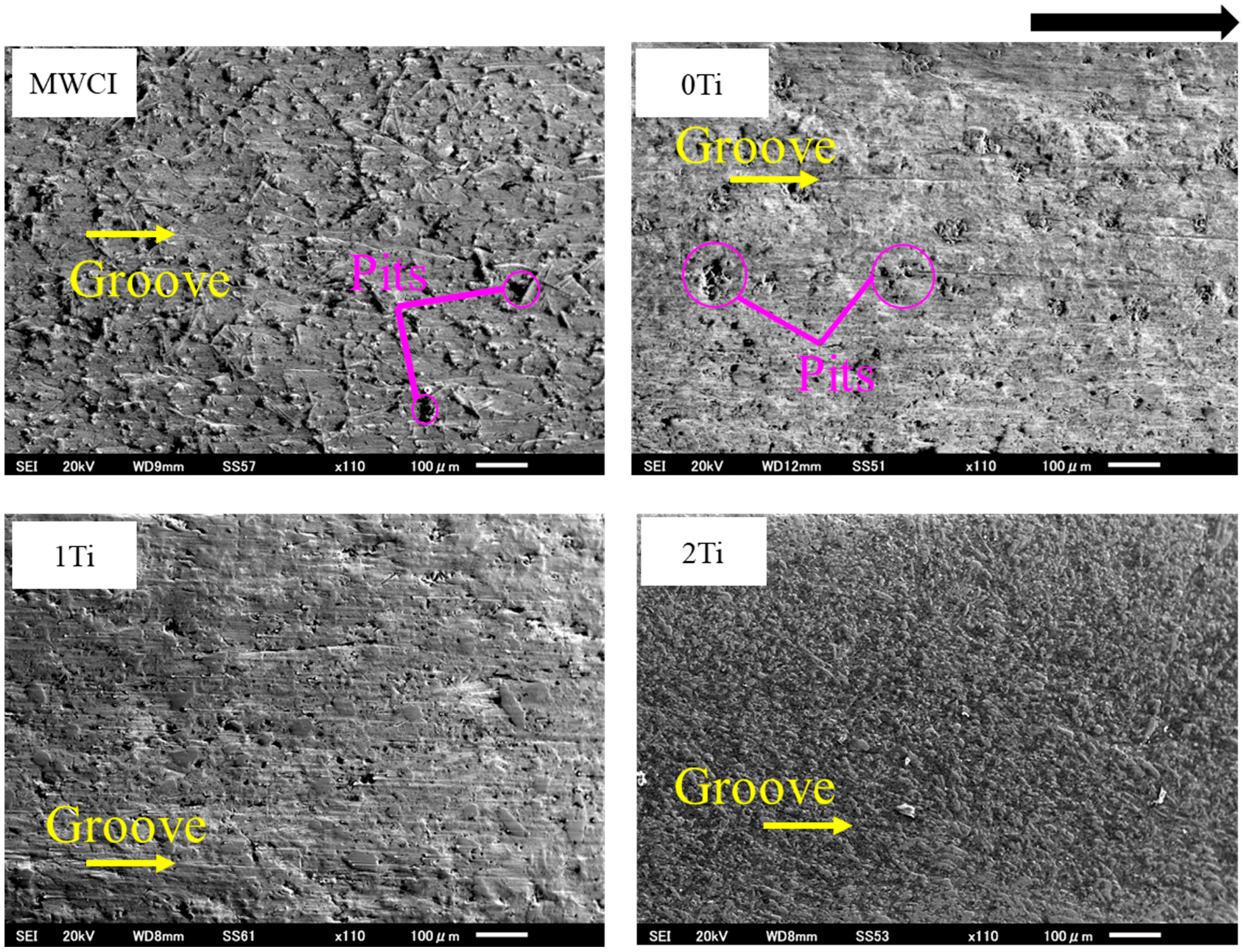
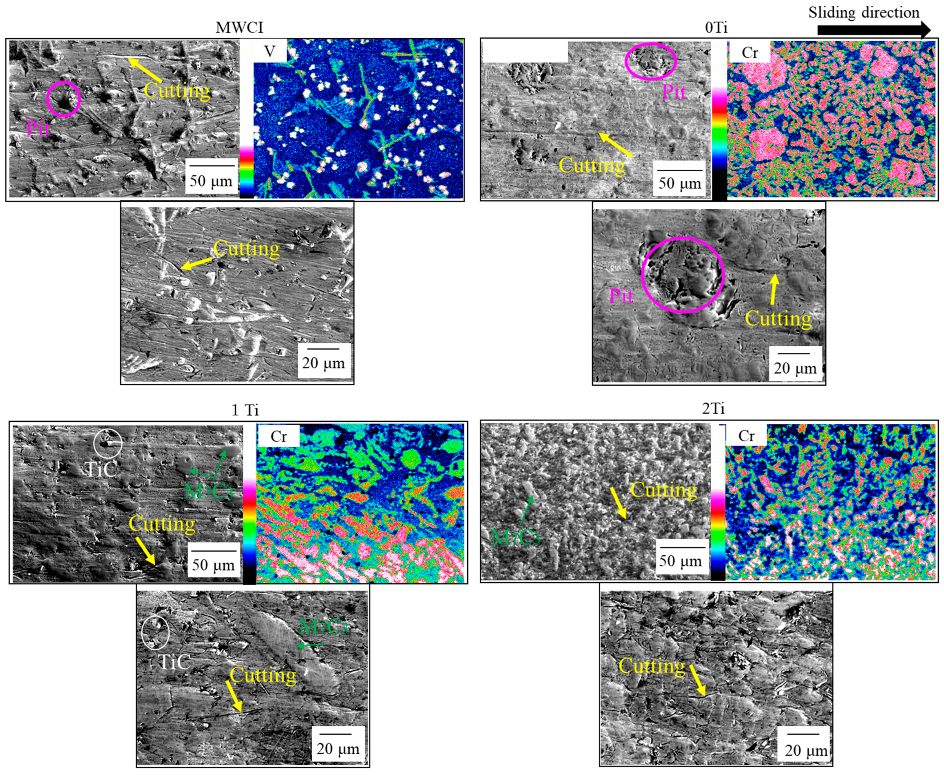
3.3.1. Observation via the Worn Surface of Materials

In general, the worn surface of the material is important to investigate to obtain the mechanism of abrasive wear [38]. Hence, this aspect was also observed in the present study, as shown in Figure 10. It can be observed that all materials are subjected to abrasive wear, with an indication of micro-grooving occurring on the wear surface. In addition, the presence of micro-pitting can also be observed in MWCI and 0Ti specimens. Additionally, it can be observed that the more severe worn surface conditions belong to 2Ti and MWCI specimens and the better ones belong to 0Ti and 2Ti specimens. This result is in accordance with the wear performance of each material. In other words, it can be determined that the more severe wear surface conditions following the test have a lower abrasive wear resistance.
To obtain more detailed information, this was analyzed via higher magnifications performed on the SEM. The results are presented in Figure 11. It can be observed that the presence of micro-cutting on all worn surfaces was mostly localized in the matrix area. Since the hardness of silica sand (1100 HV) was much higher than matrix hardness of each material, it allowed the matrix of each material to be easily cut during the test. Thus, the micro-cutting sign can be seen on the worn surface of material. In addition, more obvious micro-pitting was also present on the worn surfaces of MWCI and 0Ti. With the support of EDS mapping, the presence of these micropits mainly occurred in the VC region in the case of MWCI and in the M7C3 carbide of 0Ti. However, it is difficult to observe on the surfaces of 1Ti and 2Ti. Moreover, it can be argued that the M7C3 carbide of these two specimens still firmly stand after the test. In addition, TiC carbides also presented the same condition as M7C3 carbides in the case of 1Ti. However, presence of TiC cannot be observed on the worn surface of 2Ti specimens. Since fine TiC carbides have high hardness properties, it is difficult to abrade them by silica sand during the test. However, they can be simultaneously abraded by abrasive particles when the hardness of the material is too low. Therefore, it can be determined that the main three-abrasive mechanism of this study is micro-cutting, and the sub-mechanism is micro-pitting.

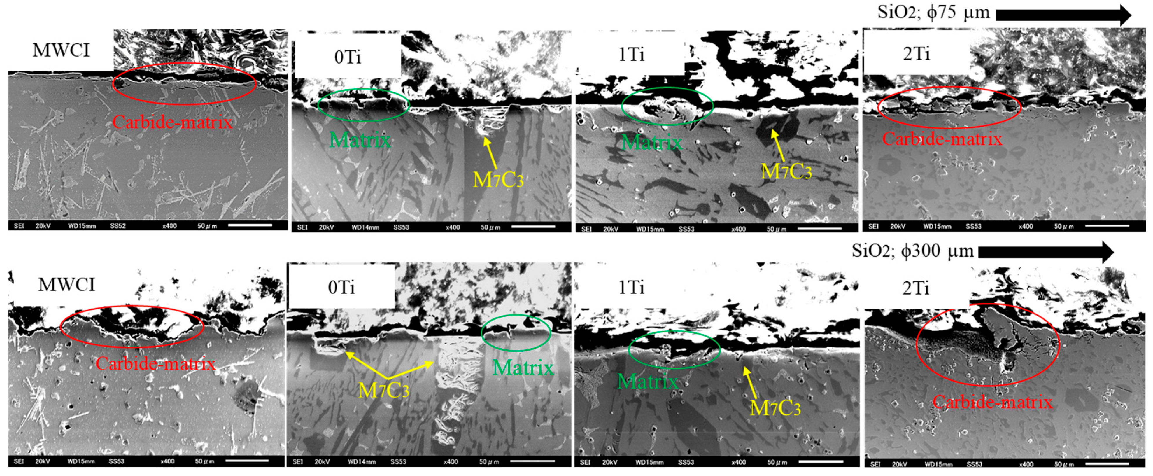
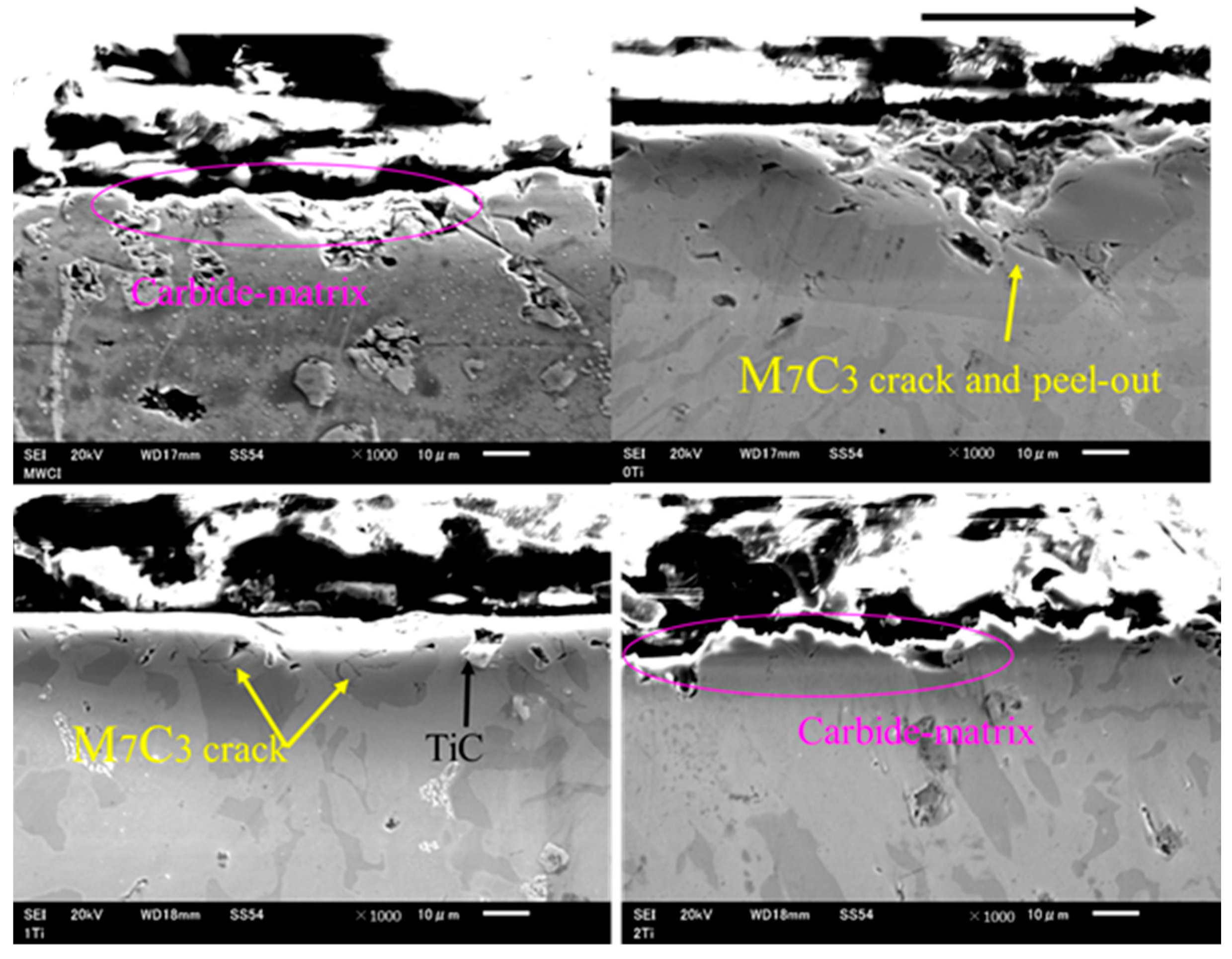
3.3.2. Observation via a Cross-Section

The cross-sections of the most abraded surfaces following testing with small and large abrasive particles are presented in Figure 12. The cross-sections of MWCI appear to be in a better condition than the others and it degrades as the amount of Cr and Ti additions increases. The better condition of MWCI may be due to its higher hardness value than the other samples. In addition, the condition of the 0Ti matrix appears to be better than 1Ti and 2Ti. Since elemental Ti can form TiC carbides during the solidification process, it must consume more elemental C, which leads to the lower solubility of C in the matrix and eventually reduces the hardness of the material. This condition may be a contributor to the poorer matrix conditions of 1Ti and 2Ti than 0Ti. However, the condition of M7C3 carbides in 0Ti is more severe than that of 1Ti specimen. This shows that the large, primary M7C3 carbides tend to crack and peel off immediately during the test. Since larger M7C3 carbide contains more Cr as described previously in Table 2, it might have higher hardness. However, its fracture toughness is lower or more brittle than smaller M7C3 carbide, which is in good agreement with the results of the previous studies [38,39]. Consequently, the abrasive wear resistance of 0Ti is quite similar to that of the 1Ti specimens.
The result also reveals that all materials experience the same phenomenon when compared with large silica sand. It can be observed that increasing the abrasive particle size deteriorates the abrasive wear resistance of the material. In addition, the condition of the large, primary M7C3 carbide is more severe than that of 1Ti, as presented in Figure 13. This means that the Ti element effectively reduces the tendency of carbide cracking due to refinement. On the other hand, the matrix of 1Ti is more severe when compared to 0Ti, which is the same as the case after being tested using small silica sand. Additionally, the cross-sections of the 0Ti and 1Ti specimens present a condition that is better than that of MWCI and 2Ti in relation to the abrasive wear performance of each material. It can be understood that since the CVF of MWCI was only approximately 22.45%, the matrix was easily abraded by larger silica sand, resulting in greater material loss compared to 0Ti and 1Ti. Meanwhile, this silica sand first abraded the matrix, leaving the micro-cutting marks when the test was conducted on 0Ti, 1Ti, and 2Ti. Thus, a lower matrix-hardness value has a lower abrasive wear-resistance outcome. Then, once the abrasive particles exert highly concentrated stresses on the M7C3 carbide, it easily breaks this large phase, leaving micro-pitting on the surface. This can be used as evidence that the larger M7C3 is more brittle. This fact may be a contributor to the similar wear-resistance properties of 0Ti and 1Ti, despite the higher hardness value and CVF. However, when the size of these primary carbides is too small, they are simultaneously abraded by large silica sand, leading to greater material loss. This may be a factor that is important for the lower abrasive wear resistance of 2Ti compared to 0Ti and 1Ti. The absence of M2C carbides due to the higher quantity of TiC carbides in the microstructure of 2Ti may also decrease its abrasive wear-resistance property. To simplify this observation, a schematic diagram of the tested cross-section with large silica sand was created, as presented in Figure 14. It exhibits that the large silica sand simultaneously scrubbed the carbide and the matrix in the case of MWCI and 2Ti specimens. In addition, the M7C3 carbide of 0Ti was easily cracked by the large silica sand as a result of its brittleness. Meanwhile, the M7C3 carbide of 1Ti was more resistant to abrasion due to the smaller size of the carbide, despite presenting a severer matrix condition. From the present investigation, it can be determined that the abrasive wear characteristics of this alloy highly depends on the microstructure constituents (carbide type and size, CVF), matrix hardness, and silica sand size.

4. Conclusions

The effect of the addition of titanium on the abrasive wear characteristics of high-Cr-based MWCI was systematically investigated in the present study. All the results can be summarized as follows:
  • MWCI has a higher hardness value, which makes it difficult for small silica sand particles to abrade the surface of the material, meaning that it also achieves better wear-resistance properties than the other specimens.
  • However, 0Ti and 1Ti present higher wear-resistance properties compared to MWCI, despite having lower hardness when tested with large silica sand particles. This is due to the higher CVF that precipitates in the microstructure of these two materials during the solidification process.
  • It is known that the size of M7C3 carbides decreases due to the precipitation of TiC. Therefore, this effectively reduces the cracking tendency of M7C3 carbides. Consequently, the wear-resistance property of a 1% Ti addition is comparable to that of 0% Ti, even though it has a lower hardness characteristic.
  • It is important to investigate the microstructure constituents (carbide types and CVF), hardness of the material, and abrasive particle size to attain comprehensive knowledge of the abrasive wear characteristics of alloys.

Author Contributions

Writing—original draft preparation, formal analysis, conceptualization, investigation, reviewing and editing: R.H.P.; resources and supervision: K.S.; formal analysis and resources: K.K. All authors have read and agreed to the published version of the manuscript.

Funding

This study was partially supported by the Japan Society for the Promotion of Science KAKENHI, Grant Number 20K05146.

Data Availability Statement

The data presented in this study are available upon request from the corresponding author.

Conflicts of Interest

The authors declare no conflict of interest.

References

  1. Mang, T.; Bobzin, K.; Bartels, T. Industrial Tribology. Tribosystem, Friction, Wear, and Surface Engineering, Lubrication; Wiley-VCH: Weinheim, Germany, 2011; pp. 1–47. [Google Scholar]
  2. Holmberg, K.; Erdemir, A. Influence of tribology on global energy consumption, cost and emissions. Friction 2017, 5, 263–284. [Google Scholar] [CrossRef] [Green Version]
  3. Tylczak, J.H. Abrasive Wear ASM Handbook; ASM International: Almere, The Netherlands, 1992. [Google Scholar]
  4. Gundlach, R.B.; Parks, J.L. Influence of abrasive hardness on the wear resistance of high chromium irons. Wear 1978, 46, 97–108. [Google Scholar] [CrossRef]
  5. Dogan, O.N.; Laird, G.; Hawk, J.A. Solidification structure and abrasion resistance of high chromium white cast irons. Metall. Mater. Trans. A 1997, 28, 1315–1328. [Google Scholar] [CrossRef]
  6. Badisch, E.; Katsich, C.; Winckelmann, H.; Franek, F.; Roy, M. Wear behaviour of hard-faced Fe-Cr-C alloy and austenitic steel under 2-body and 3-body conditions at elevated temperature. Tribol. Int. 2010, 43, 1234–1244. [Google Scholar] [CrossRef]
  7. Shimizu, K.; Purba, R.H.; Kusumoto, K.; Year, X.; Ito, J.; Kasuga, H.; Gaqi, Y. Microstructural evaluation and high-temperature erosion characteristic of high chromium cast irons. Wear 2019, 426–427, 420–427. [Google Scholar] [CrossRef]
  8. Coronado, J.J. Effect of (Fe, Cr)7C3 carbide orientation on abrasion wear resistance and fracture toughness. Wear 2011, 270, 287–293. [Google Scholar] [CrossRef]
  9. Cheng, H.X.; Chang, Z.C.; Lu, J.C.; Lin, H.T. Effect of Niobium on wear resistance of 15% Cr white cast iron. Wear 1993, 166, 197–201. [Google Scholar] [CrossRef]
  10. Radulovic, M.; Fiset, M.; Peev, K.; Tomovic, M. The influence of vanadium on fracture toughness and abrasion resistance in high chromium white cast irons. J. Mater. Sci. 1994, 29, 5085–5094. [Google Scholar] [CrossRef]
  11. Guerra, F.V.; Jaquinde, A.B.; Silva, J.Z.; Meija, I.; Legorreta, E.C.; Flores, A.A. Effect of the simultaneous Ti and W addition on the microstructure and wear behavior of a high chromium white cast iron. Metall. Res. Technol. 2019, 116, 602. [Google Scholar] [CrossRef]
  12. Takeuchi, A.; Inoue, A. Classification of bulk metallic glasses by atoic size difference, heat of mixing and period of constituent elements and its application to characterization of the main alloying element. Mater. Trans. 2005, 46, 2817–2829. [Google Scholar] [CrossRef]
  13. Wang, Y.P.; Li, D.Y.; Parent, I.; Tian, H. Improving the wear resistance of white cast iron using a new concept-high-entropy microstructure. Wear 2011, 271, 1623–1628. [Google Scholar] [CrossRef]
  14. Suzuki, A.S.A. Effect of multiply charged ions on the vickers hardness of TiC films. Jpn. J. Appl. Phys. 1999, 38, 881. [Google Scholar] [CrossRef]
  15. Stevenson, A.N.J.; Hutchings, I.M. Wear of hardfacing white cast irons by solid particle erosion. Wear 1995, 186–187, 150–158. [Google Scholar] [CrossRef]
  16. Berns, H.; Fischer, A. Microstructure of Fe-Cr-C hardfacing alloys with additions of Nb, Ti and, B. Metallography 1987, 20, 401–429. [Google Scholar] [CrossRef]
  17. Zhu, C.; Fordyce, I.; Sun, S.D.; Annasamy, M.; Fabijanic, D.; Short, K.; Paradowska, A.; Leary, M.; Brandt, M.; Easton, M. Effect of Ti and TiC additions on the microstructure and wear resistance of high chromium white irons produced by laser directed energy deposition. Wear 2022, 510–511, 204519. [Google Scholar] [CrossRef]
  18. Zhou, Y.F.; Yang, Y.L.; Yang, J.; Zhang, P.F.; Qi, X.W.; Ren, X.J.; Yang, Q.X. Wear resistance of hypereutectic Fe–Cr–C hardfacing coatings with in situ formed TiC. Surf. Eng. 2013, 29, 366–373. [Google Scholar] [CrossRef]
  19. Ibrahim, K.M.; Nofal, A.A. Effect of titanium addition on structure and properties of the as-cast high Cr-Mo white iron. Int. J. Mater. Res. 2013, 103, 362–370. [Google Scholar] [CrossRef]
  20. Chung, R.J.; Tang, X.; Li, D.Y.; Hinckley, B.; Dolman, K. Effect of titanium addition on the microstructure and wear resistance of hypereutectic high chromium cast iron Fe-25wt.%Cr-4wt.%C. Wear 2009, 267, 356–361. [Google Scholar] [CrossRef]
  21. Matsubara, Y.; Sasaguri, N.; Shimizu, K.; Yu, S.K. Solidification and abrasion wear of white cast irons alloyed with 20% carbide forming elements. Wear 2001, 250, 502–510. [Google Scholar] [CrossRef]
  22. Kusumoto, K.; Shimizu, K.; Yaer, X.; Zhang, Y.; Ota, Y.; Ito, J. Abrasive wear characteristics of Fe-2C-5Cr-5Mo-5W-5Nb multi-component white cast iron. Wear 2017, 376–377, 22–29. [Google Scholar] [CrossRef]
  23. Opapaiboon, J.; Ayudhaya, M.S.N.; Sricharoenchai, P.; Inthidech, S.; Matsubara, Y. Effect of chromium content on three-boy-type abrasive wear behavior of multi-alloyed cast iron. J. Met. Mater. Miner. 2018, 28, 94–105. [Google Scholar] [CrossRef]
  24. De Mello, J.D.B.; Polycarpou, A.A. Abrasive wear mechanism of multi-components ferrous alloys abraded by soft, fine abrasive particles. Wear 2010, 269, 911–920. [Google Scholar] [CrossRef]
  25. Kusumoto, K.; Shimizu, K.; Yaer, X.; Hara, H.; Tamura, K.; Kawai, H. High erosion-oxidation performance of Fe-based Nb or V containing multicomponent alloys with Co addition at 1173 K. Mater. Des. 2015, 88, 366–374. [Google Scholar] [CrossRef]
  26. Tabrett, C.P.; Sare, I.R. The effect of heat treatment on the abrasion resistance of alloy white cast irons. Wear 1997, 203–204, 206–219. [Google Scholar] [CrossRef]
  27. Wang, J.; Li, C.; Liu, H.; Yang, H.; Shen, B.; Gao, S.; Huang, S. The precipitation and transformation of secondary carbides in high chromium cast iron. Mater. Charact. 2006, 56, 73–78. [Google Scholar] [CrossRef]
  28. Karantzalis, A.E.; Lekatou, A.; Mavros, H. Microstructure modification of as-cast high chromium white cast iron by heat treatment. J. Mater. Eng. Perform. 2009, 18, 174–181. [Google Scholar] [CrossRef]
  29. Kishore, K.; Kumar, U.; Dinesh, N.; Adhikary, M. Effect of soaking temperature on carbide precipitation, hardness, and wear resistance of high chromium cast iron. J. Fail. Anal. Prev. 2020, 20, 24–260. [Google Scholar] [CrossRef]
  30. Purba, R.H.; Shimizu, K.; Kusumoto, K.; Gaqi, Y. Comparison of Three-Body Abrasion Behaviors of High-Cr-Mo- and High-Cr-Based Multicomponent White Cast Irons. J. Mater. Eng. Perform. 2022. [Google Scholar] [CrossRef]
  31. Filipovic, M.; Kamberovic, Z.; Korac, M.; Jordovic, B. Effect of niobium and vanadium additions on as-cast microstructure and properties of hypoeutectic Fe-Cr-C alloy. ISIJ Int. 2013, 53, 2160–2166. [Google Scholar] [CrossRef] [Green Version]
  32. Ding, J.; Deng, C.J.; Yuan, W.J.; Zhu, H.X.; Li, J. Preparation of porous TiC/C ceramics using wooden template in molten salt media. Adv. Appl. Ceram. 2013, 11, 131–135. [Google Scholar] [CrossRef]
  33. Tong, J.M.; Zhou, Y.-Z.; Sheng, T.Y.; Deng, H.J. The influence of retained austenite in high chromium cast iron on impact-abrasive wear. Wear 1990, 135, 217–226. [Google Scholar] [CrossRef]
  34. Xi, J.T.; Zhou, Q.D.; Liu, S.H.; Song, G.S. Influence of retained austenite on wear resistance of high chromium cast iron under various impact loads. Wear 1993, 162–164, 83–88. [Google Scholar] [CrossRef]
  35. Zang, Y.; Shimizu, K.; Kusumoto, K.; Hara, H.; Higuchi, C. Influence of Ni addition on erosive wear characteristics of multi-component white cast iron at elevated temperature. Wear 2017, 376–377, 452–457. [Google Scholar] [CrossRef]
  36. Rabinowicz, E.; Mutis, A. Effect of abrasive particle size on wear. Wear 1965, 8, 381–390. [Google Scholar] [CrossRef]
  37. Todaka, T.; Shimizu, K.; Kusumoto, K.; Purba, R.H.; Gaqi, Y. Effect carbon content on three-body abrasive wear characteristics of 28Cr-3Ni cast alloys. ISIJ Int. 2021, 61, 2274–2283. [Google Scholar] [CrossRef]
  38. Zum Gahr, K.H.; Eldis, G.T. Abrasive wear of white cast irons. Wear 1980, 64, 175–194. [Google Scholar] [CrossRef]
  39. Purba, R.H.; Shimizu, K.; Kusumoto, K.; Gaqi, Y.; Todaka, T. Effect of boron addition on three-body abrasive wear characteristics of high chromium based multi-component white cast iron. Mater. Chem. Phys. 2022, 275, 125232. [Google Scholar] [CrossRef]
Figure 1. The schematic of the destabilization heat-treatment process for each specimen.
Jmmp 07 00021 g001
Figure 2. A rubber wheel three-body abrasive wear machine test according to the ASTM G65 standard.
Jmmp 07 00021 g002
Figure 3. (a,c) are silica sand (SiO2) particles with average diameters of 75 and 300 µm; (b,d) are the size distributions of SiO2 samples’ average diameters, 75 and 300 µm, respectively.
Jmmp 07 00021 g003
Figure 4. The microstructure of the materials after being etched in hydrochloric liquid.
Jmmp 07 00021 g004
Figure 5. The microstucture of materials and the distribution of each added element using SEM-EDS equipment.
Jmmp 07 00021 g005
Figure 6. Matrix and secondary-carbide observation through high magnification via SEM.
Jmmp 07 00021 g006
Figure 7. (a) Total CVF of each material; XRD patterns of (b) MWCI and (c) 0Ti.
Jmmp 07 00021 g007
Figure 8. The distribution of primary M7C3 carbide sizes of 0Ti, 1Ti, and 2Ti specimens.
Jmmp 07 00021 g008
Figure 9. The relationship between Vickers hardness and abrasive wear rate of the materials.
Jmmp 07 00021 g009
Figure 10. The worn surface of each specimen after being tested with silica sand ϕ 300 μm.
Jmmp 07 00021 g010
Figure 11. The worn surface of each material after the test with the silica sand ϕ 300 μm observed via high magnification on SEM-EDS equipment.
Jmmp 07 00021 g011
Figure 12. The cross-section of each material after being tested with small and big silica sand particles.
Jmmp 07 00021 g012
Figure 13. The cross-section of each material after being tested with big silica sand particles with highly magnified SEM.
Jmmp 07 00021 g013
Figure 14. The schematic of abrasive wear on all specimens for large silica sand.
Jmmp 07 00021 g014
Table 1. Chemical composition of each specimen (wt.%).
SpecimenCCrMoVWCoTiFe
MWCI2.564.845.264.794.904.89-Bal.
0Ti3.0926.792.923.532.942.86-Bal.
1Ti3.0026.372.833.542.822.811.19Bal.
2Ti2.9926.482.813.482.802.842.49Bal.
Disclaimer/Publisher’s Note: The statements, opinions and data contained in all publications are solely those of the individual author(s) and contributor(s) and not of MDPI and/or the editor(s). MDPI and/or the editor(s) disclaim responsibility for any injury to people or property resulting from any ideas, methods, instructions or products referred to in the content.

