

Unleashing the Potential of Morphing Wings: A Novel Cost Effective Morphing Method for UAV Surfaces, Rear Spar Articulated Wing Camber

Abstract
:1. Introduction
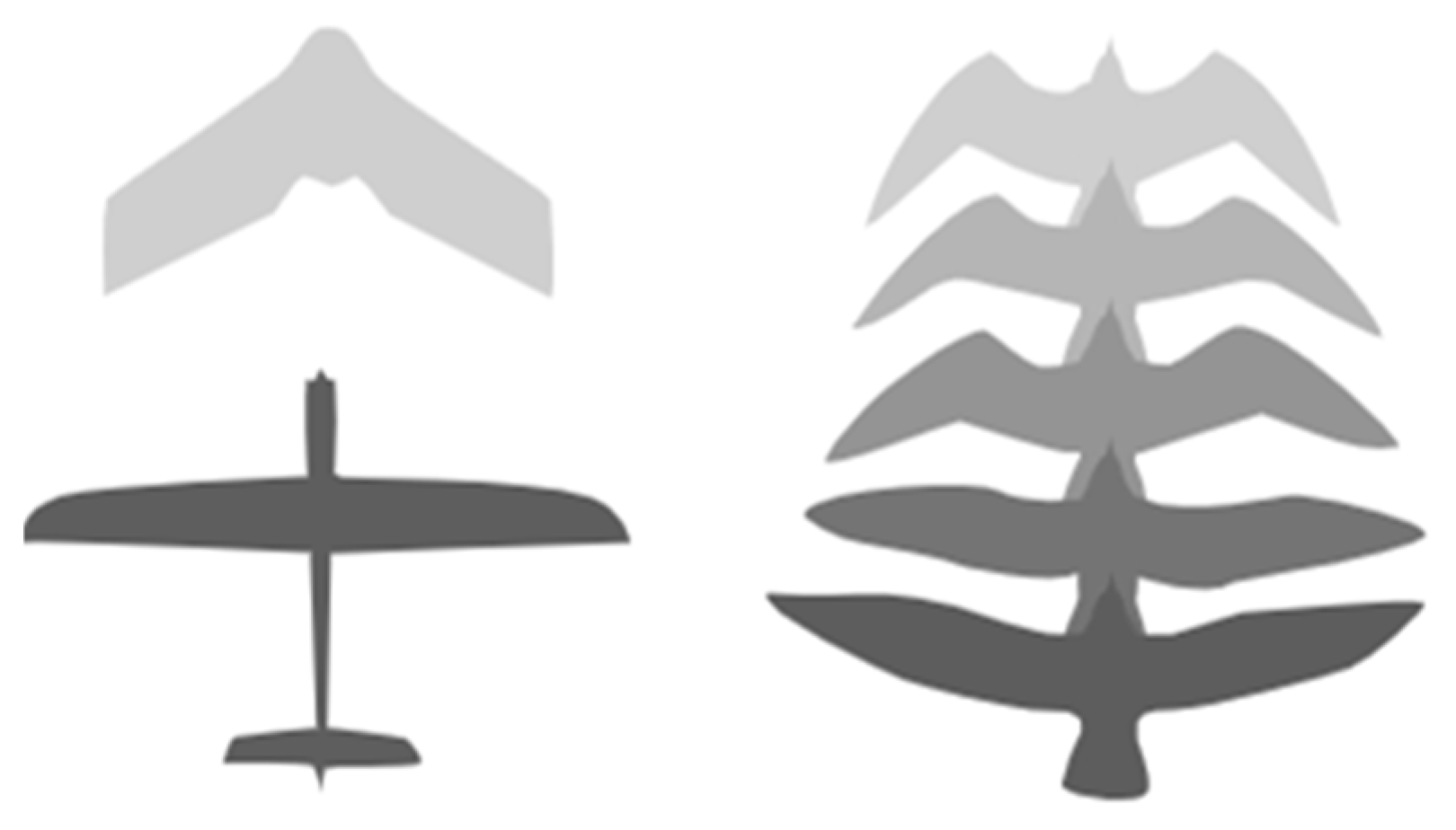
1.1. The Motivation behind the Morphing Structures
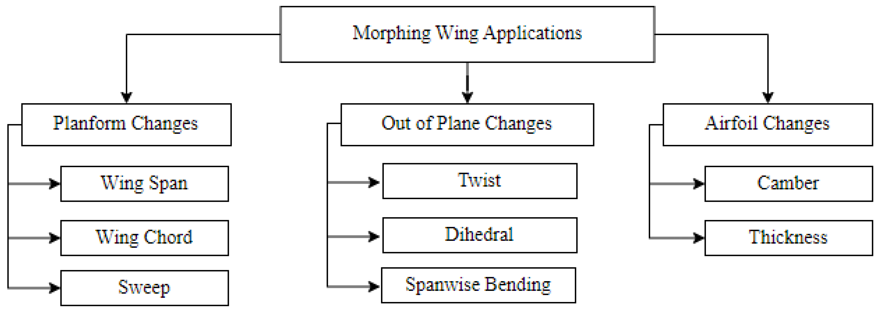
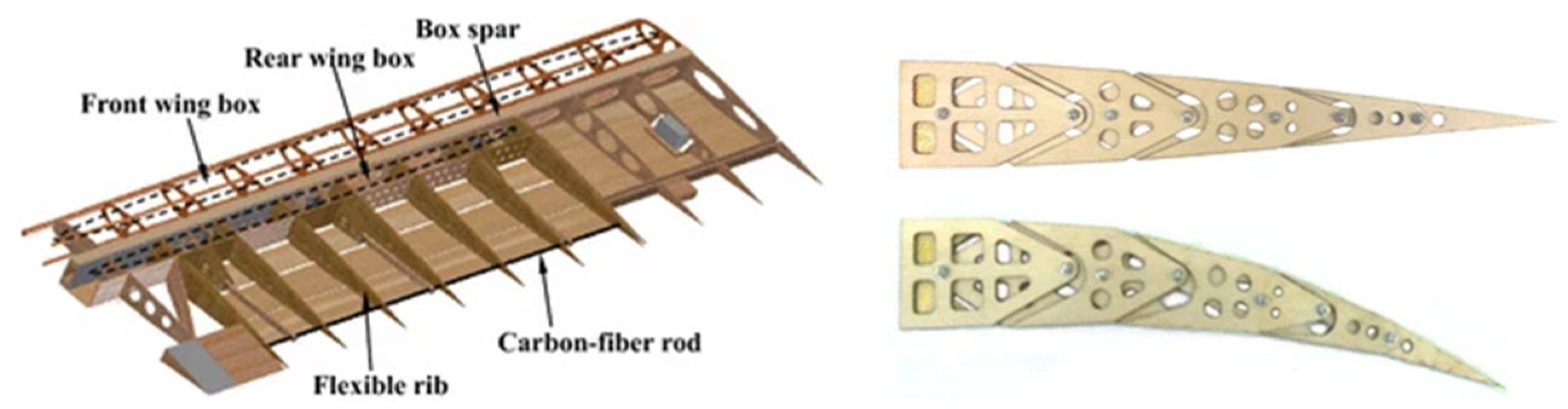
1.2. A Literature Survey on Morphing Wings of UAVs
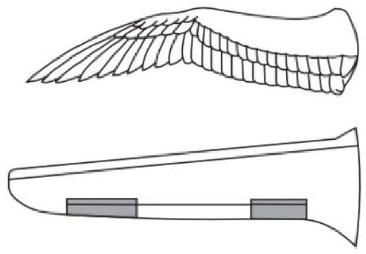
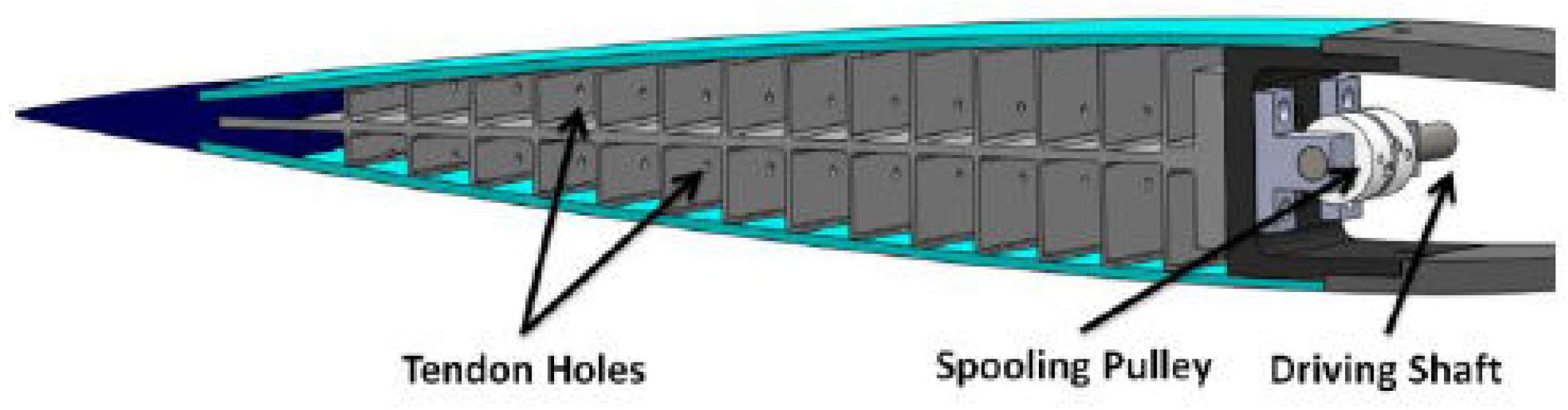
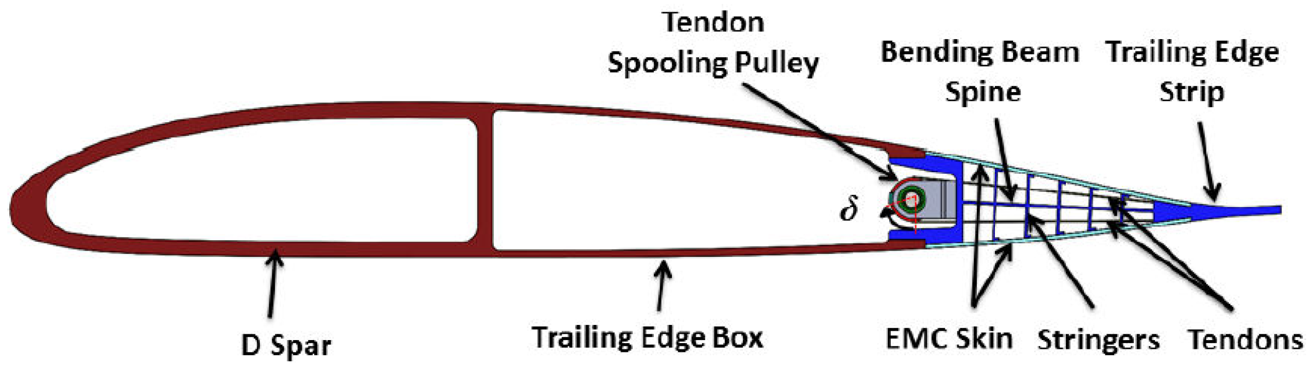
1.3. Fish Bone Articulated Camber Morphing Concept
- Control Authority;
- Simplicity;
- Reliability.
1.4. Conclusions from the FishBAC Concept Literature Survey
1.5. Novelty of This Research
2. The Design Process of Rear Spar Articulated Wing Camber (RSAWC)
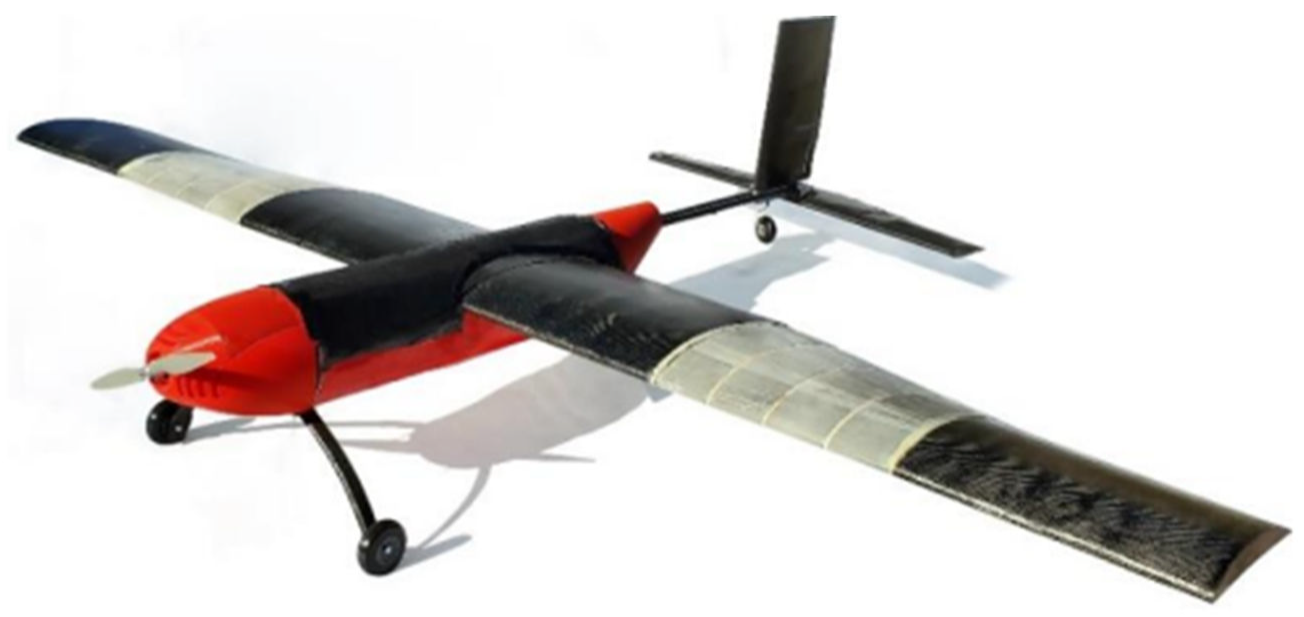
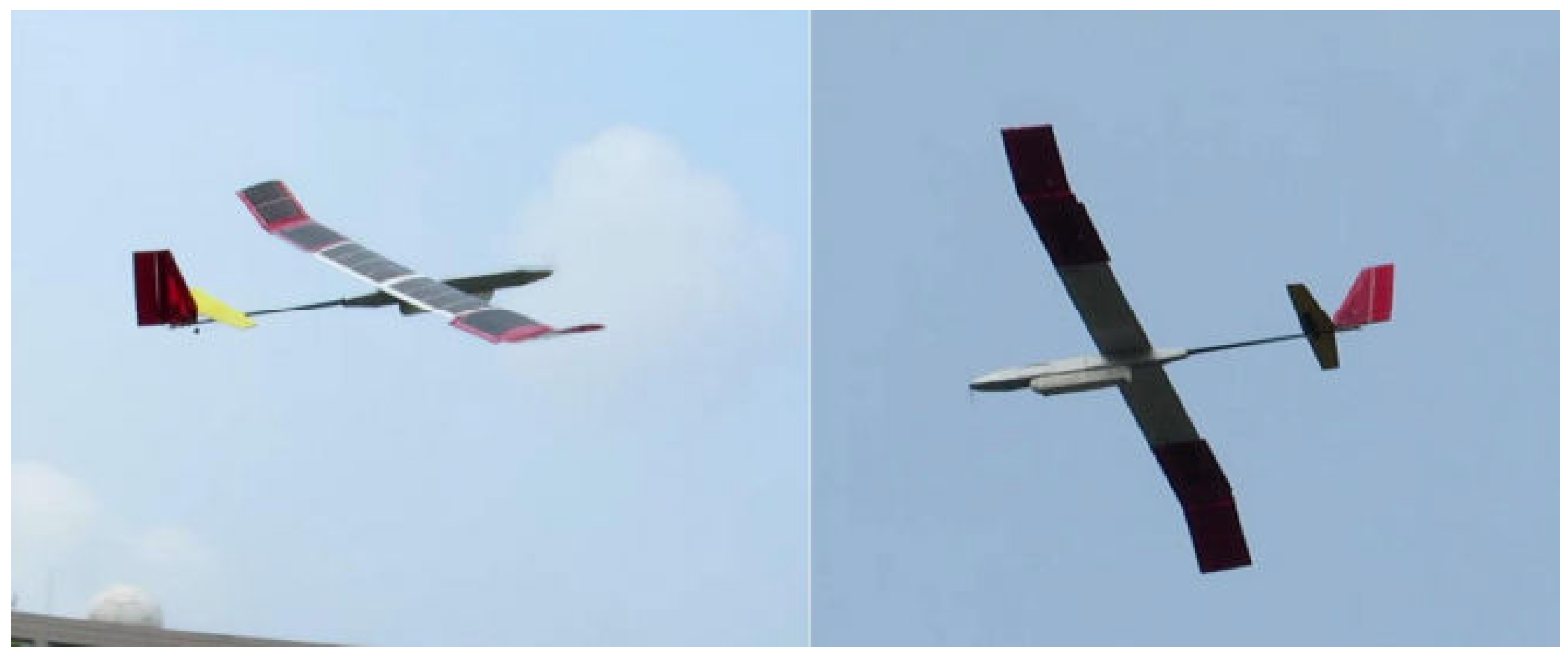
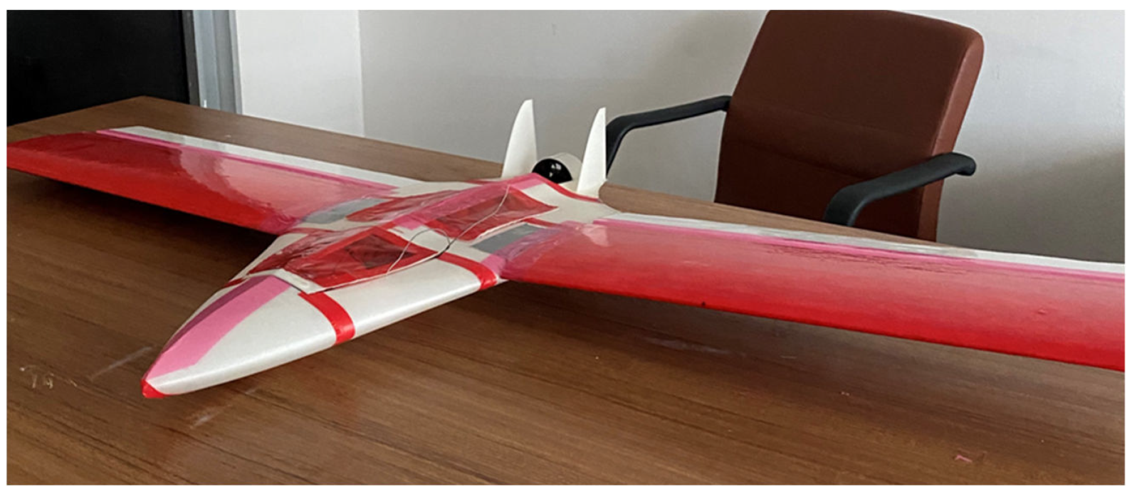
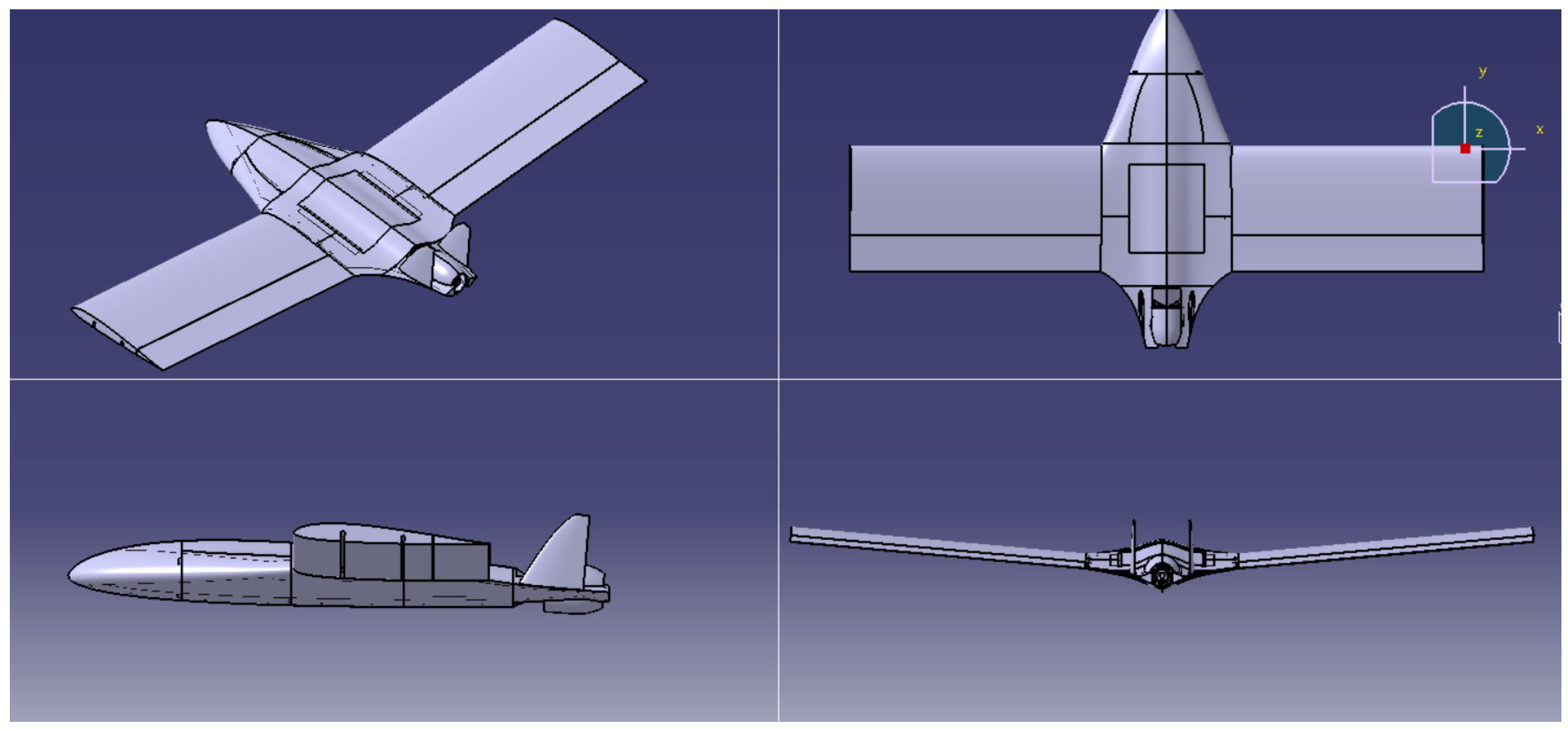
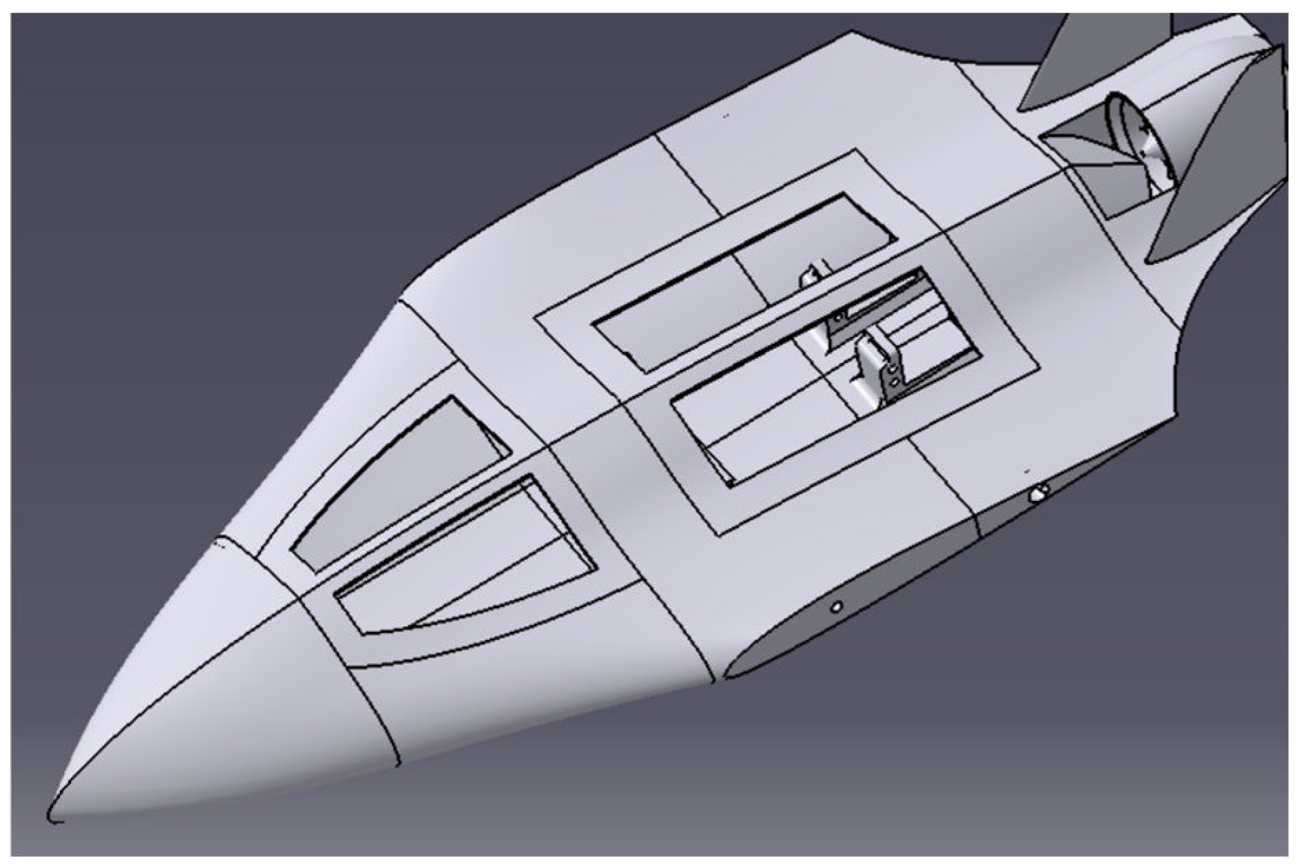
2.1. Test Platform: The Stingray UAV
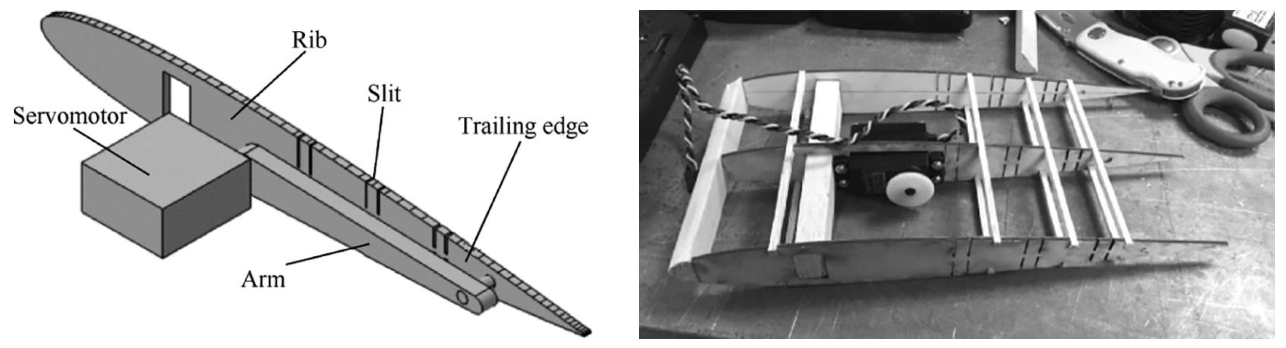
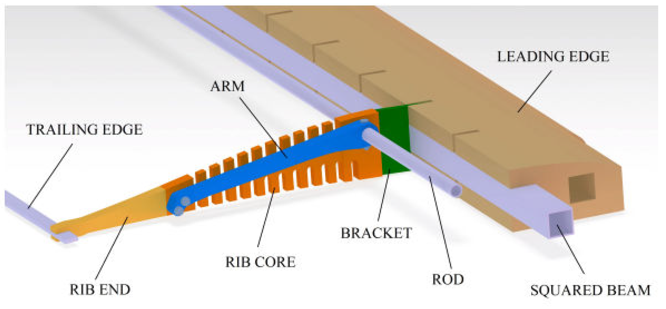
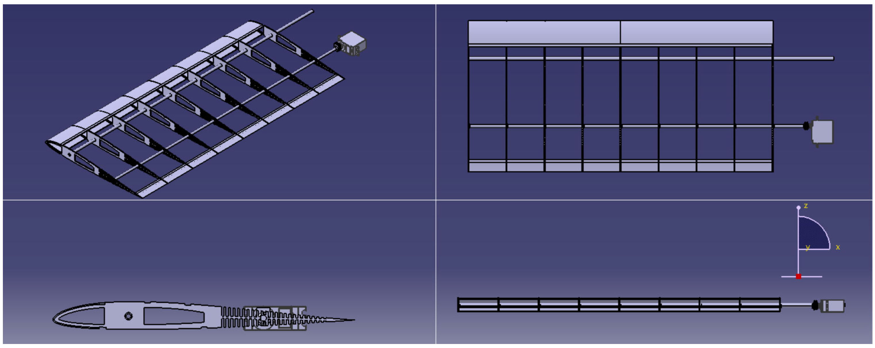
2.2. RSAWC Wing Development for the Stingray UAV
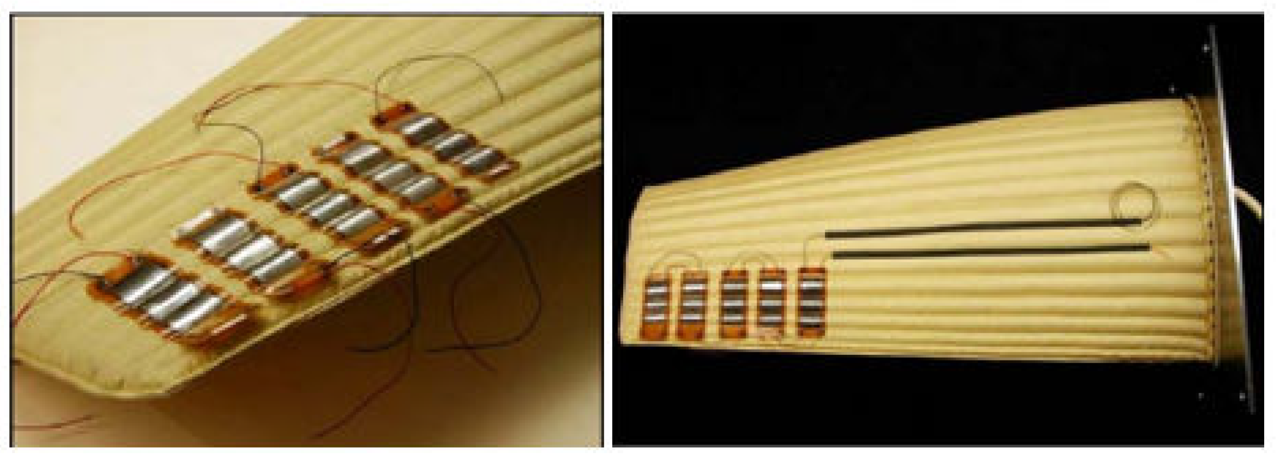
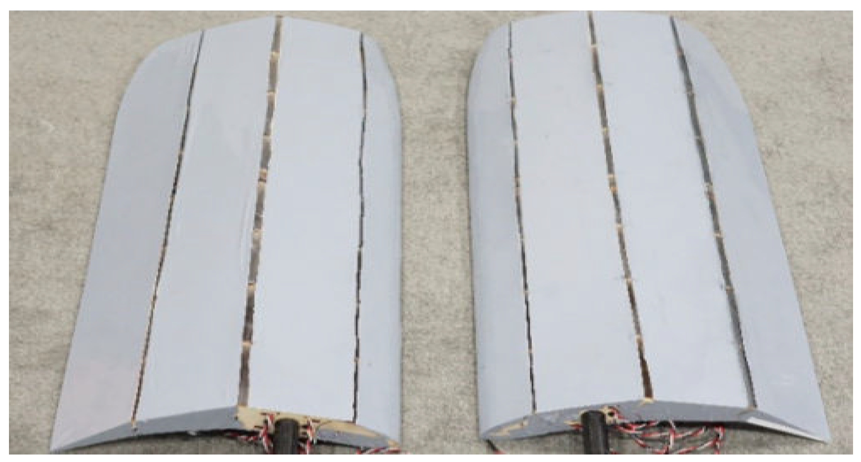
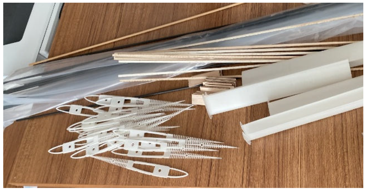
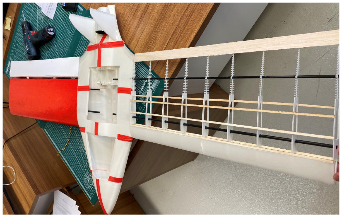
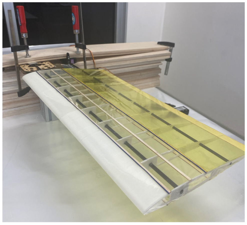
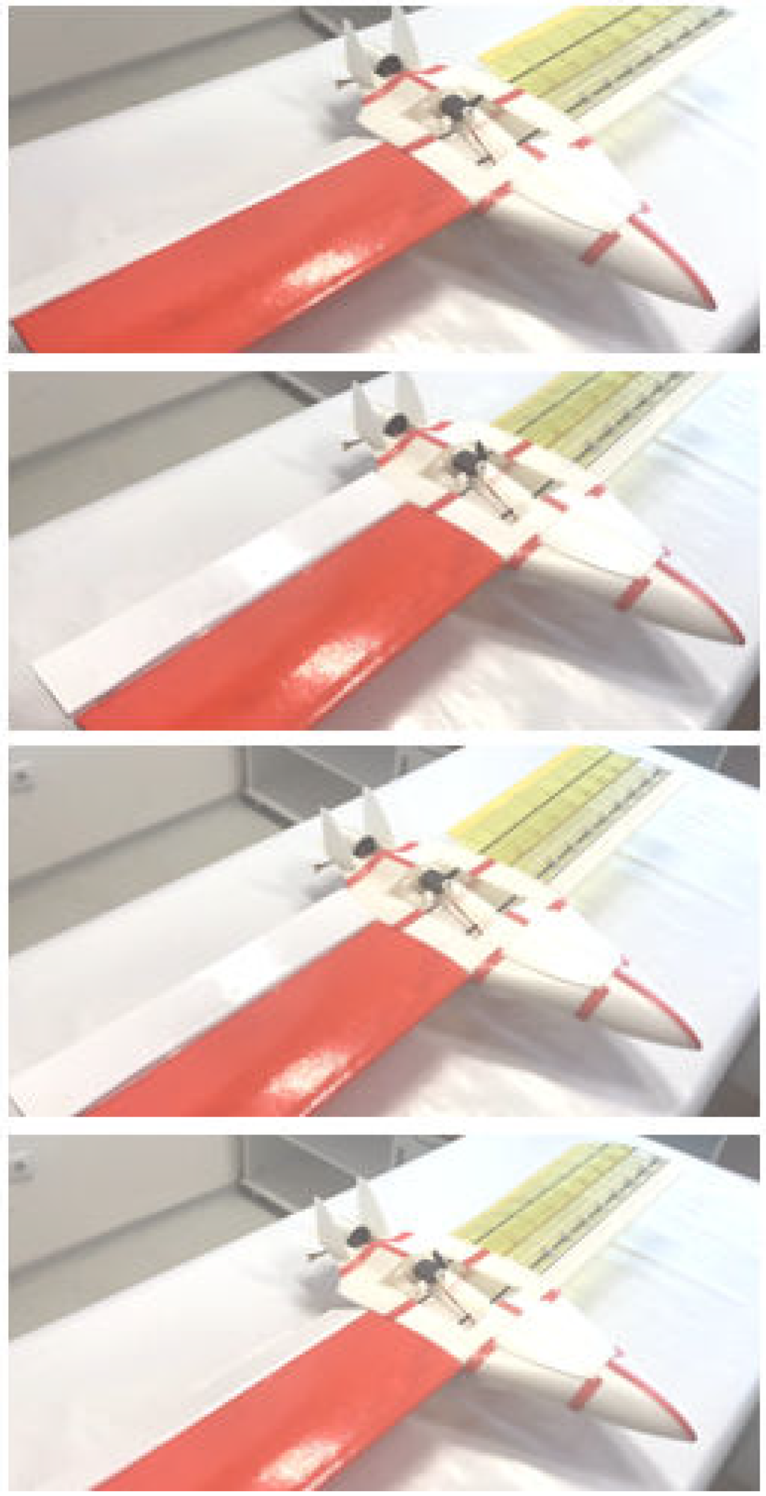
2.3. RSAWC Wing Manufacture of the Stingray UAV
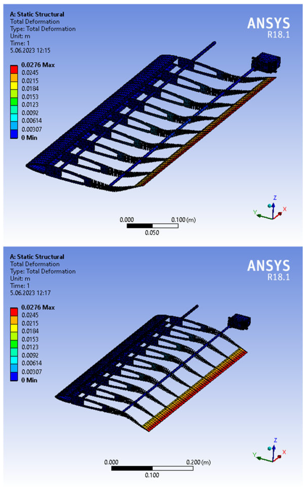
- The torque of the selected servo is appropriate when considering the tolerance value applied to the wing without cover.
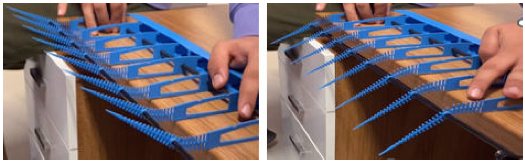
- Continuous control authority has been achieved during upward and downward movements, as well as during transitions between movements.
- The differences between the rib deformations observed in the analysis performed by the finite element method were also observed in this functional test. It is anticipated that the deformation differences between the ribs will be eliminated with the addition of the cover.
3. Desktop Testing of RSAWC Wing Concept
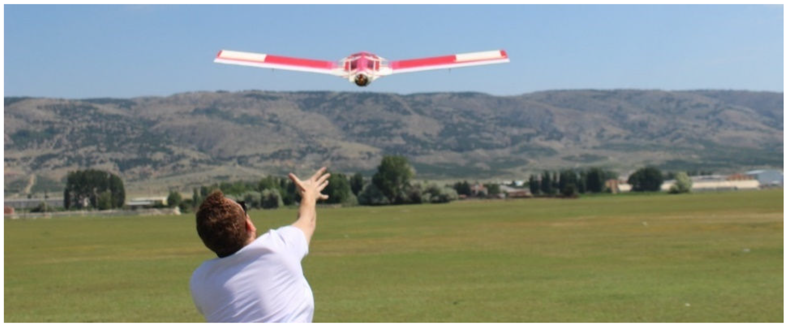
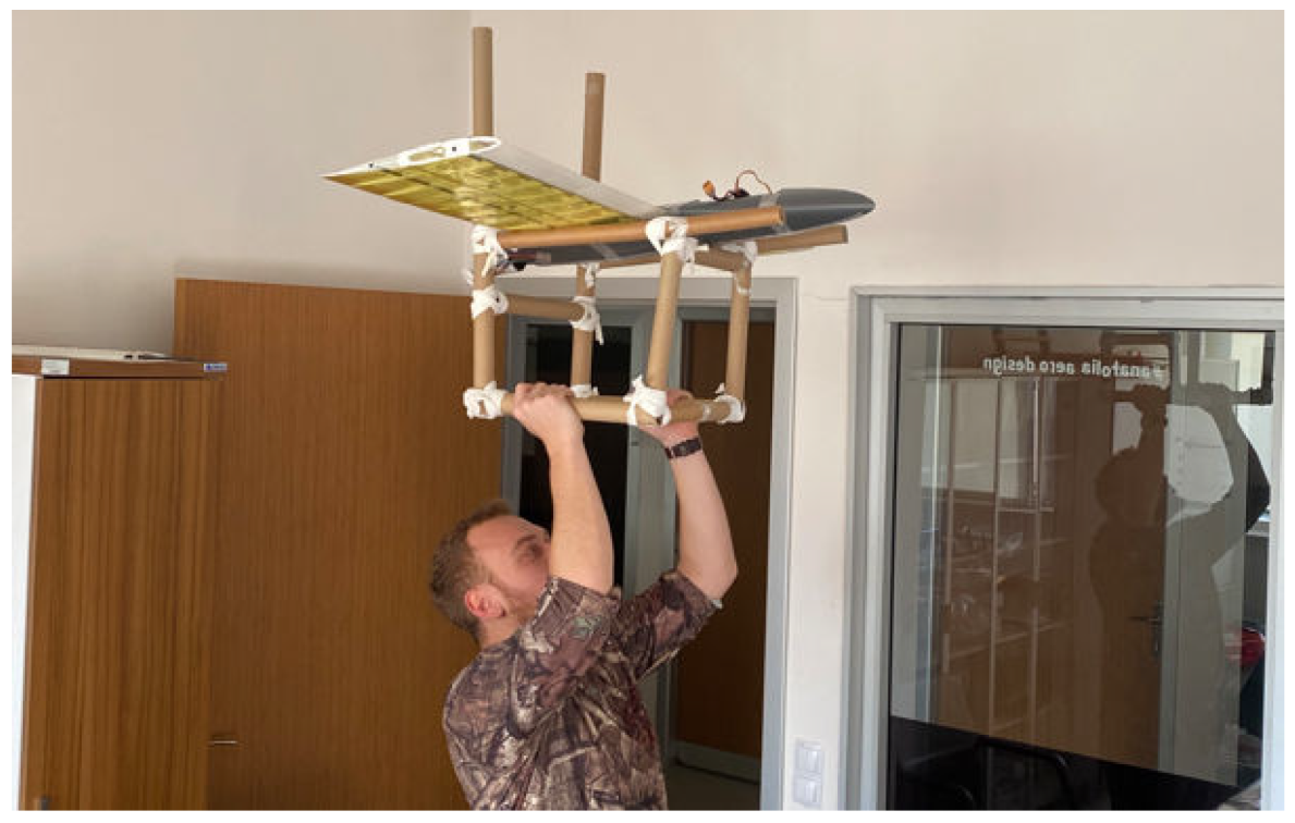
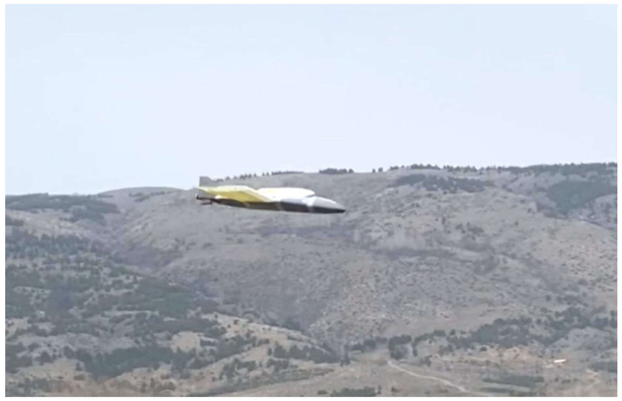
4. Flight Testing of RSAWC Wing Concept
5. Results and Discussion
5.1. Complexity Evaluation
5.2. Weight Evaluation
5.3. Cost Evaluation
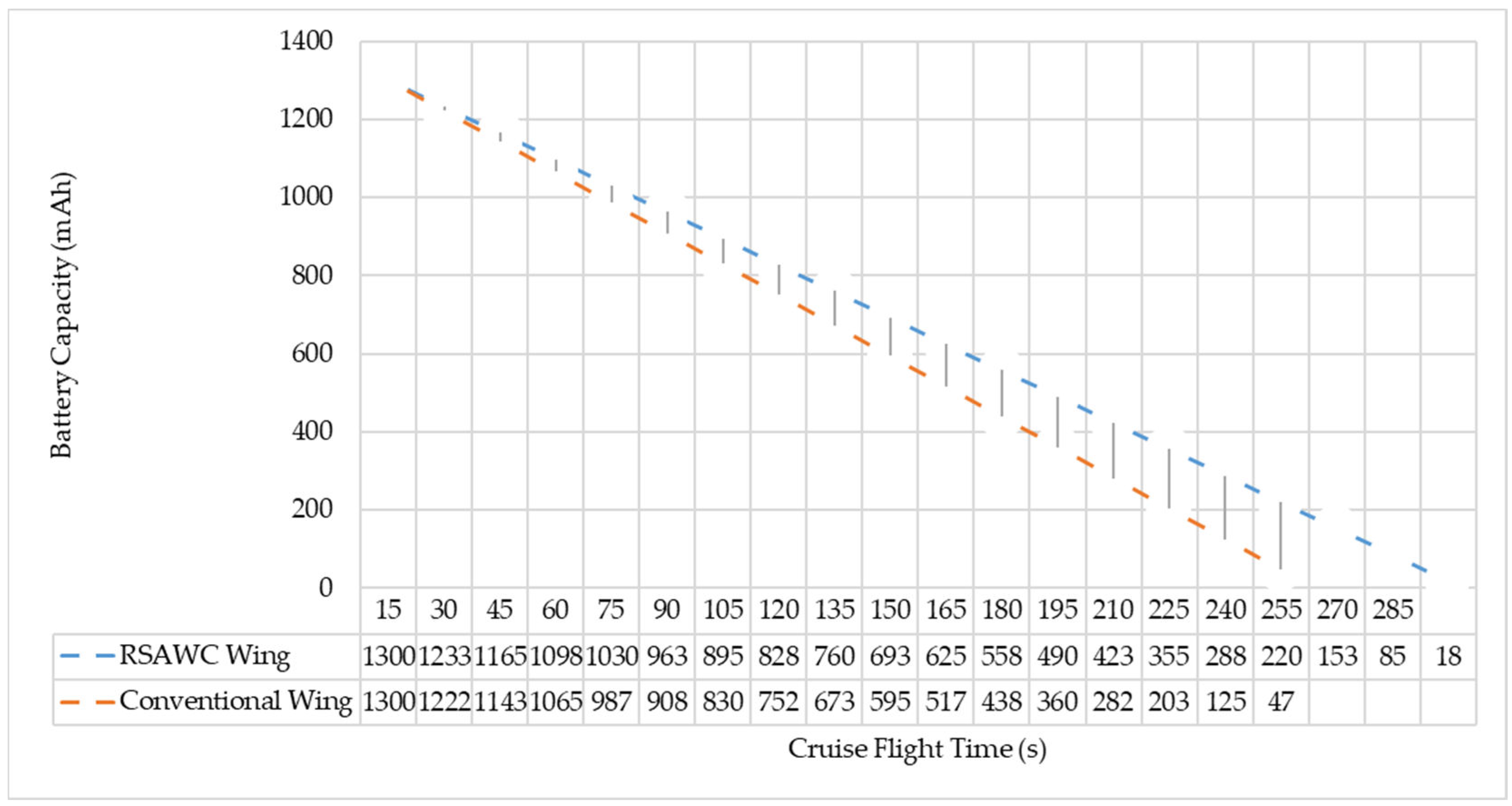
5.4. Performance Evaluation
6. Conclusions
Future Directions on RSAWC Concept Research
7. Patents
Author Contributions
Funding
Data Availability Statement
Conflicts of Interest
References
- Singh, M. Civil Aviation in India: Historical Perspective. Asian J. Res. Soc. Sci. Humanit. 2013, 3, 199–206. [Google Scholar]
- Lee, S.; Choi, Y. Comparison of Topographic Surveying Results using a Fixed-wing and a Popular Rotary-wing Unmanned Aerial Vehicle (Drone). Tunn. Undergr. Space 2016, 26, 24–31. [Google Scholar] [CrossRef] [Green Version]
- Razzaq, S.; Xydeas, C.; Mahmood, A.; Ahmed, S.; Ratyal, N.I.; Iqbal, J. Efficient optimization techniques for resource allocation in UAVs mission framework. PLoS ONE 2023, 18, e0283923. [Google Scholar] [CrossRef] [PubMed]
- Lentink, D.; Müller, U.K.; Stamhuis, E.J.; de Kat, R.; van Gestel, W.; Veldhuis, L.L.M.; Henningsson, P.; Hedenström, A.; Videler, J.J.; van Leeuwen, J.L. How swifts control their glide performance with morphing wings. Nature 2007, 446, 1082–1085. [Google Scholar] [CrossRef] [PubMed]
- Yu, Y.; Guan, Z. Learning from bat: Aerodynamics of actively morphing wing. Theor. Appl. Mech. Lett. 2015, 5, 13–15. [Google Scholar] [CrossRef] [Green Version]
- Taylor, G.K.; Carruthers, A.C.; Hubel, T.Y.; Walker, S.M. Wing Morphing in Insects, Birds and Bats: Mechanism and Function. In Morphing Aerospace Vehicles and Structures; Valasek, J., Ed.; Wiley: New Delhi, India, 2012; pp. 11–40. ISBN 9780470972861. [Google Scholar]
- Dorobantu, A.; Ozdemir, A.A.; Turkoglu, K.; Freeman, P.; Murch, A.; Mettler, B.; Balas, G. Frequency Domain System Identification for a Small, Low-Cost, Fixed-Wing UAV. In Proceedings of the AIAA Guidance, Navigation, and Control Conference, Portland, OR, USA, 8–11 August 2011; American Institute of Aeronautics and Astronautics: Reston, VA, USA, 2011. ISBN 978-1-60086-952-5. [Google Scholar]
- Busan, R.C.; Murphy, P.C.; Hatke, D.B.; Simmons, B.M. Wind Tunnel Testing Techniques for a Tandem Tilt-Wing, Distributed Electric Propulsion VTOL Aircraft. In Proceedings of the AIAA Scitech 2021 Forum, Virtual Event, 11–15 & 19–21 January 2021; American Institute of Aeronautics and Astronautics: Reston, VA, USA, 2021; p. 2015, ISBN 978-1-62410-609-5. [Google Scholar]
- Alviani, R.; Blaisdell, G.A.; Poggie, J. Computational Analysis of Planned High-Speed Swept Wing-Elevon Experiments. In Proceedings of the AIAA SCITECH 2022 Forum, San Diego, CA, USA & Virtual, 3–7 January 2022; American Institute of Aeronautics and Astronautics: Reston, VA, USA, 2022; p. 77, ISBN 978-1-62410-631-6. [Google Scholar]
- Abdulrahim, M. Flight Dynamics and Control of an Aircraft with Segmented Control Surfaces. In Proceedings of the 42nd AIAA Aerospace Sciences Meeting and Exhibit, Reno, NV, USA, 5–8 January 2004; American Institute of Aeronautics and Astronautics: Reston, VA, USA, 2004. ISBN 978-1-62410-078-9. [Google Scholar]
- Stowers, A.K.; Lentink, D. Folding in and out: Passive morphing in flapping wings. Bioinspir. Biomim. 2015, 10, 25001. [Google Scholar] [CrossRef] [Green Version]
- Harvey, C.; Baliga, V.B.; Goates, C.D.; Hunsaker, D.F.; Inman, D.J. Gull-inspired joint-driven wing morphing allows adaptive longitudinal flight control. J. R. Soc. Interface 2021, 18, 20210132. [Google Scholar] [CrossRef]
- Li, D.; Zhao, S.; Da Ronch, A.; Xiang, J.; Drofelnik, J.; Li, Y.; Zhang, L.; Wu, Y.; Kintscher, M.; Monner, H.P.; et al. A review of modelling and analysis of morphing wings. Prog. Aerosp. Sci. 2018, 100, 46–62. [Google Scholar] [CrossRef] [Green Version]
- Science World. Can You Flap and Fly? Available online: https://www.scienceworld.ca/resource/can-you-flap-and-fly/ (accessed on 19 April 2023).
- Dhileep, K.; Kumar, D.; Gautham Vigneswar, P.N.; Soni, P.; Ghosh, S.; Ali, S.F.; Arockiarajan, A. Aerodynamic study of single corrugated variable-camber morphing aerofoil concept. Aeronaut. J. 2022, 126, 316–344. [Google Scholar] [CrossRef]
- Wakayama, S. Subsonic Multi-Role Aircraft. In Proceedings of the 44th AIAA Aerospace Sciences Meeting and Exhibit, Reno, NV, USA, 9–12 January 2006; American Institute of Aeronautics and Astronautics: Reston, VA, USA, 2006. ISBN 978-1-62410-039-0. [Google Scholar]
- Joshi, S.; Tidwell, Z.; Crossley, W.; Ramakrishnan, S. Comparison of Morphing Wing Stategies Based upon Aircraft Performance Impacts. In Proceedings of the 45th AIAA/ASME/ASCE/AHS/ASC Structures, Structural Dynamics & Materials Conference, Palm Springs, CA, USA, 19–22 April 2004; American Institute of Aeronautics and Astronautics: Reston, VA, USA, 2004. ISBN 978-1-62410-079-6. [Google Scholar]
- Harvey, C.; Baliga, V.B.; Lavoie, P.; Altshuler, D.L. Wing morphing allows gulls to modulate static pitch stability during gliding. J. R. Soc. Interface 2019, 16, 20180641. [Google Scholar] [CrossRef]
- Ekici, F.; Orhan, G.; Gümüş, Ö.; Bahce, A.B. A policy on the externality problem and solution suggestions in air transportation: The environment and sustainability. Energy 2022, 258, 124827. [Google Scholar] [CrossRef]
- Lee, J.J. Can we accelerate the improvement of energy efficiency in aircraft systems? Energy Convers. Manag. 2010, 51, 189–196. [Google Scholar] [CrossRef]
- Federal Aviation Administration. Aviation Emissions, Impacts and Mitigation: A Primer. Available online: https://www.faa.gov/regulations_policies/policy_guidance/envir_policy/media/primer_jan2015.pdf (accessed on 19 April 2023).
- Pecora, R. Morphing wing flaps for large civil aircraft: Evolution of a smart technology across the Clean Sky program. Chin. J. Aeronaut. 2021, 34, 13–28. [Google Scholar] [CrossRef]
- Akshayraj, N.; Arockia Dhanraj, J.; Solomon, J.M.; Salyan, S.; Subramaniam, M.; Mohan, M.; Kuppan Chetty, R.; Christu Paul, R. Design and analysis of a tail sitter (VTOL) UAV composite wing. Mater. Today Proc. 2022, 56, 1604–1613. [Google Scholar] [CrossRef]
- Jini Raj, R.; Bruce Ralphin Rose, J.; Vasudevan, A. Analysis of Bio-inspired Fishbone Based Corrugated Rib for Adaptive Camber Morphing. J. Bionic Eng. 2023, 20, 1083–1102. [Google Scholar] [CrossRef]
- Pecora, R.; Amoroso, F.; Lecce, L. Effectiveness of Wing Twist Morphing in Roll Control. J. Aircr. 2012, 49, 1666–1674. [Google Scholar] [CrossRef]
- Garcia, H.; Abdulrahim, M.; Lind, R. Roll Control for a Micro Air Vehicle Using Active Wing Morphing. In Proceedings of the AIAA Guidance, Navigation, and Control Conference and Exhibit, Austin, TX, USA, 11–14 August 2003; American Institute of Aeronautics and Astronautics: Reston, VA, USA, 2003; p. 2134, ISBN 978-1-62410-090-1. [Google Scholar]
- Dussart, G.X.; Yusuf, S.Y.; Lone, M.M. Effect of wingtip morphing on the roll mode of a flexible aircraft. In Proceedings of the 2018 AIAA/ASCE/AHS/ASC Structures, Structural Dynamics, and Materials Conference, Kissimmee, FL, USA, 3–7 January 2022; American Institute of Aeronautics and Astronautics: Reston, VA, USA, 2018; p. 555, ISBN 978-1-62410-532-6. [Google Scholar]
- Ozbek, E.; Yalin, G.; Karaoglan, M.U.; Ekici, S.; Colpan, C.O.; Karakoc, T.H. Architecture design and performance analysis of a hybrid hydrogen fuel cell system for unmanned aerial vehicle. Int. J. Hydrog. Energy 2021, 46, 16453–16464. [Google Scholar] [CrossRef]
- Ofoma, U.; Wu, C. Design of a Fuel Cell Powered UAV for Environmental Research. In Proceedings of the AIAA 3rd “Unmanned Unlimited” Technical Conference, Workshop and Exhibit, Chicago, IL, USA, 20–23 September 2004; American Institute of Aeronautics and Astronautics: Reston, VA, USA, 2004; p. 1993, ISBN 978-1-62410-081-9. [Google Scholar]
- Turk, I.; Ozbek, E.; Ekici, S.; Karakoc, T.H. A conceptual design of a solar powered UAV and assessment for continental climate flight conditions. Int. J. Green Energy 2022, 19, 638–648. [Google Scholar] [CrossRef]
- Lukaszewicz, A.; Szafran, K.; Jozwik, J. CAx Techniques Used in UAV Design Process. In Proceedings of the 2020 IEEE 7th International Workshop on Metrology for AeroSpace (MetroAeroSpace), Pisa, Italy, 22–24 June 2020; IEEE, 2020; pp. 95–98, ISBN 978-1-7281-6636-0. [Google Scholar]
- Ajmera, D.; Saroliya, M.; Arora, P. Unmanned Aerial Vehicles (UAVs). Int. Res. J. Innov. Eng. Technol. 2022, 6, 22–27. [Google Scholar]
- Rodriguez, A. Morphing Aircraft Technology Survey. In Proceedings of the 45th AIAA Aerospace Sciences Meeting and Exhibit, Reno, NV, USA, 8–11 January 2007; American Institute of Aeronautics and Astronautics: Reston, VA, USA, 2007; pp. 1–16, ISBN 978-1-62410-012-3. [Google Scholar]
- Schmidt, R.K. The Design of Aircraft Landing Gear; SAE International: Warrendale, PA, USA, 2020; ISBN 9780768099423. [Google Scholar]
- Knowles, J.A.C.; Krauskopf, B.; Lowenberg, M. Numerical continuation analysis of a three-dimensional aircraft main landing gear mechanism. Nonlinear Dyn. 2013, 71, 331–352. [Google Scholar] [CrossRef] [Green Version]
- Jha, A.K.; Kudva, J.N. Morphing aircraft concepts, classifications, and challenges. In Proceedings of the Smart Structures and Materials 2004: Industrial and Commercial Applications of Smart Structures Technologies, San Diego, CA, USA, 14 March 2004; Anderson, E.H., Ed.; SPIE: Bellingham, WA, USA, 2004; p. 213. [Google Scholar]
- Barbarino, S.; Bilgen, O.; Ajaj, R.M.; Friswell, M.I.; Inman, D.J. A Review of Morphing Aircraft. J. Intell. Mater. Syst. Struct. 2011, 22, 823–877. [Google Scholar] [CrossRef]
- Nangia, R.; Palmer, M.; Tilmann, C. Unconventional High Aspect Ratio Joined-Wing Aircraft with Aft and Forward-Swept Wing-Tips. In Proceedings of the 41st Aerospace Sciences Meeting and Exhibit, Reno, NV, USA, 6–9 January 2003; American Institute of Aeronautics and Astronautics: Reston, VA, USA, 2003; pp. 1–11, ISBN 978-1-62410-099-4. [Google Scholar]
- Elijah, T.; Jamisola, R.S.; Tjiparuro, Z.; Namoshe, M. A review on control and maneuvering of cooperative fixed-wing drones. Int. J. Dynam. Control 2021, 9, 1332–1349. [Google Scholar] [CrossRef]
- Samuel, J.B.; Pines, D. Design and Testing of a Pneumatic Telescopic Wing for Unmanned Aerial Vehicles. J. Aircr. 2007, 44, 1088–1099. [Google Scholar] [CrossRef]
- Mestrinho, J.; Gamboa, P.; Santos, P. Design Optimization of a Variable-Span Morphing Wing for a Small UAV. In Proceedings of the 52nd AIAA/ASME/ASCE/AHS/ASC Structures, Structural Dynamics and Materials Conference, Denver, CO, USA, 4–7 April 2011; American Institute of Aeronautics and Astronautics: Reston, VA, USA, 2011. ISBN 978-1-60086-951-8. [Google Scholar]
- Ajaj, R.M.; Saavedra Flores, E.I.; Friswell, M.I.; Allegri, G.; Woods, B.K.S.; Isikveren, A.T.; Dettmer, W.G. The Zigzag wingbox for a span morphing wing. Aerosp. Sci. Technol. 2013, 28, 364–375. [Google Scholar] [CrossRef]
- Ajaj, R.M.; Friswell, M.I.; Bourchak, M.; Harasani, W. Span morphing using the GNATSpar wing. Aerosp. Sci. Technol. 2016, 53, 38–46. [Google Scholar] [CrossRef] [Green Version]
- Ajaj, R.M.; Jankee, G.K. The Transformer aircraft: A multimission unmanned aerial vehicle capable of symmetric and asymmetric span morphing. Aerosp. Sci. Technol. 2018, 76, 512–522. [Google Scholar] [CrossRef] [Green Version]
- Perkins, D.; Reed, J.; Havens, E. Morphing Wing Structures for Loitering Air Vehicles. In Proceedings of the 45th AIAA/ASME/ASCE/AHS/ASC Structures, Structural Dynamics & Materials Conference, Palm Springs, CA, USA, 19–22 April 2004; American Institute of Aeronautics and Astronautics: Reston, VA, USA, 2004. ISBN 978-1-62410-079-6. [Google Scholar]
- Barbarino, S.; Gandhi, F.; Webster, S.D. Design of Extendable Chord Sections for Morphing Helicopter Rotor Blades. J. Intell. Mater. Syst. Struct. 2011, 22, 891–905. [Google Scholar] [CrossRef]
- Siouris, S.; Qin, N. Study of the effects of wing sweep on the aerodynamic performance of a blended wing body aircraft. Proc. Inst. Mech. Eng. Part G J. Aerosp. Eng. 2007, 221, 47–55. [Google Scholar] [CrossRef]
- Foster, G.; Morris, O. Stability and Control Characteristics at a Mach Number of 1.97 of an Airplane Configuration Having Two Types of Variable-Sweep Wings. Available online: https://ntrs.nasa.gov/api/citations/19660022441/downloads/19660022441.pdf (accessed on 19 April 2023).
- Spencer, B. Stability and Control Characteristics at Low Subsonic Speeds of an Airplane Configuration Having Two Types of Variable-Sweep Wings. Available online: https://ntrs.nasa.gov/api/citations/19660024029/downloads/19660024029.pdf (accessed on 19 April 2023).
- Panagiotou, P.; Antoniou, S.; Yakinthos, K. Cant angle morphing winglets investigation for the enhancement of the aerodynamic, stability and performance characteristics of a tactical Blended-Wing-Body UAV. Aerosp. Sci. Technol. 2022, 123, 107467. [Google Scholar] [CrossRef]
- Greatwood, C.; Waldock, A.; Richardson, T. Perched landing manoeuvres with a variable sweep wing UAV. Aerosp. Sci. Technol. 2017, 71, 510–520. [Google Scholar] [CrossRef] [Green Version]
- Stodieck, O.; Cooper, J.E.; Weaver, P.M.; Kealy, P. Aeroelastic Tailoring of a Representative Wing Box Using Tow-Steered Composites. AIAA J. 2017, 55, 1425–1439. [Google Scholar] [CrossRef] [Green Version]
- Schlup, A.; Bishay, P.; Mclennan, T.; Barajas, C.; Talebian, B.; Thatcher, G.; Flores, R.; Perez-Norwood, J.; Torres, C.; Kibret, K.; et al. MataMorph 2: A new experimental UAV with twist-morphing wings and camber-morphing tail stabilizers. In Proceedings of the AIAA Scitech 2021 Forum, Virtual Event, 19–21 January 2021; American Institute of Aeronautics and Astronautics: Reston, VA, USA, 2021; p. 146, ISBN 978-1-62410-609-5. [Google Scholar]
- Tahani, M.; Masdari, M.; Bargestan, A. Aerodynamic performance improvement of WIG aircraft. AEAT 2017, 89, 120–132. [Google Scholar] [CrossRef]
- Abdulrahim, M.; Lind, R. Flight Testing and Response Characteristics of a Variable Gull-Wing Morphing Aircraft. In Proceedings of the AIAA Guidance, Navigation, and Control Conference and Exhibit, Providence, RI, USA, 16–19 August 2004; American Institute of Aeronautics and Astronautics: Reston, VA, USA, 2004. ISBN 978-1-62410-073-4. [Google Scholar]
- Wu, M.; Xiao, T.; Ang, H.; Li, H. Optimal Flight Planning for a Z-Shaped Morphing-Wing Solar-Powered Unmanned Aerial Vehicle. J. Guid. Control Dyn. 2018, 41, 497–505. [Google Scholar] [CrossRef]
- Wu, M.; Xiao, T.; Ang, H.; Li, H. Investigation of a Morphing Wing Solar-Powered Unmanned Aircraft with Enlarged Flight Latitude. J. Aircr. 2017, 54, 1996–2004. [Google Scholar] [CrossRef]
- Lazos, B.; Visser, K. Aerodynamic Comparison of Hyper-Elliptic Cambered Span (HECS) Wings with Conventional Configurations. In Proceedings of the 24th AIAA Applied Aerodynamics Conference, San Francisco, CA, USA, 5–8 June 2006; American Institute of Aeronautics and Astronautics: Reston, VA, USA, 2006; p. 265, ISBN 978-1-62410-028-4. [Google Scholar]
- Manzo, J.; Garcia, E. Demonstration of an in situ morphing hyperelliptical cambered span wing mechanism. Smart Mater. Struct. 2010, 19, 25012. [Google Scholar] [CrossRef]
- Anderson, J.D. Fundamentals of Aerodynamics, 5th ed.; SI Units; McGraw-Hill: Singapore, 2011; ISBN 9781259010286. [Google Scholar]
- Secanell, M.; Suleman, A.; Gamboa, P. Design of a Morphing Airfoil for a Light Unmanned Aerial Vehicle Using High-Fidelity Aerodynamics Shape Optimization. In Proceedings of the 46th AIAA/ASME/ASCE/AHS/ASC Structures, Structural Dynamics and Materials Conference, Austin, TX, USA, 18–21 April 2005; American Institute of Aeronautics and Astronautics: Reston, VA, USA, 2005; p. 1021, ISBN 978-1-62410-065-9. [Google Scholar]
- Zhao, W.; Jrad, M.; Gupta, R.; Kapania, R.K. Multidisciplinary Design Analysis and Optimization of Performance Adaptive Aeroelastic Wings. In Proceedings of the AIAA Atmospheric Flight Mechanics Conference, Grapevine, TX, USA, 9–13 January 2017; American Institute of Aeronautics and Astronautics: Reston, VA, USA, 2017; p. 2000, ISBN 978-1-62410-448-0. [Google Scholar]
- Jones, A.R.; Bakhtian, N.M.; Babinsky, H. Low Reynolds Number Aerodynamics of Leading-Edge Flaps. J. Aircr. 2008, 45, 342–345. [Google Scholar] [CrossRef] [Green Version]
- Karagounıs, T.; Maxworthy, T.; Speddıng, G. Generation and control of separated vortices over a delta wing by means of leading edge flaps. In Proceedings of the 2nd Shear Flow Conference, Tempe, AZ, USA, 13–16 March 1989; American Institute of Aeronautics and Astronautics: Reston, VA, USA, 1989. [Google Scholar]
- Marqués, P. Advanced UAV Aerodynamics, Flight Stability and Control. In Advanced UAV Aerodynamics, Flight Stability and Control; Marqués, P., Da Ronch, A., Eds.; John Wiley & Sons, Ltd.: Chichester, UK, 2017; pp. 1–30. ISBN 9781118928691. [Google Scholar]
- Pankonien, A.M.; Inman, D.J. Spanwise morphing trailing edge on a finite wing. In Active and Passive Smart Structures and Integrated Systems 2015, Proceedings of the SPIE Smart Structures and Materials + Nondestructive Evaluation and Health Monitoring, San Diego, CA, USA, 8 March 2015; Liao, W.-H., Ed.; SPIE: Bellingham, WA, USA, 2015; p. 94310T. [Google Scholar]
- Guo, Y.; Thomas, R.H. On Aircraft Trailing Edge Noise. In Proceedings of the 25th AIAA/CEAS Aeroacoustics Conference, Delft, The Netherlands, 20–23 May 2019; American Institute of Aeronautics and Astronautics: Reston, VA, USA, 2019. ISBN 978-1-62410-588-3. [Google Scholar]
- Jo, B.W.; Majid, T. Enhanced Range and Endurance Evaluation of a Camber Morphing Wing Aircraft. Biomimetics 2023, 8, 34. [Google Scholar] [CrossRef]
- Cheng, G.; Ma, T.; Yang, J.; Chang, N.; Zhou, X. Design and Experiment of a Seamless Morphing Trailing Edge. Aerospace 2023, 10, 282. [Google Scholar] [CrossRef]
- Cadogan, D.; Smith, T.; Uhelsky, F.; Mackusick, M. Morphing Inflatable Wing Development for Compact Package Unmanned Aerial Vehicles. In Proceedings of the 45th AIAA/ASME/ASCE/AHS/ASC Structures, Structural Dynamics & Materials Conference, Palm Springs, CA, USA, 19–22 April 2004; American Institute of Aeronautics and Astronautics: Reston, VA, USA, 2004. ISBN 978-1-62410-079-6. [Google Scholar]
- Zhao, A.; Zou, H.; Jin, H.; Wen, D. Structural design and verification of an innovative whole adaptive variable camber wing. Aerosp. Sci. Technol. 2019, 89, 11–18. [Google Scholar] [CrossRef]
- Communıer, D.; Botez, R.M.; Wong, T. Experimental validation of a new morphing trailing edge system using Price—Païdoussis wind tunnel tests. Chin. J. Aeronaut. 2019, 32, 1353–1366. [Google Scholar] [CrossRef]
- Meguid, S.A.; Su, Y.; Wang, Y. Complete morphing wing design using flexible-rib system. Int. J. Mech. Mater. Des. 2017, 13, 159–171. [Google Scholar] [CrossRef]
- Woods, B.K.S.; Friswell, M.I. Preliminary Investigation of a Fishbone Active Camber Concept. In Proceedings of the ASME 2012 Conference on Smart Materials, Adaptive Structures and Intelligent Systems, Stone Mountain, GA, USA, 19–21 September 2012; Volume 2: Mechanics and Behavior of Active Materials; Integrated System Design and Implementation; Bio-Inspired Materials and Systems; Energy Harvesting; American Society of Mechanical Engineers: New York, NY, USA, 2012; pp. 555–563. ISBN 978-0-7918-4510-3. [Google Scholar]
- Woods, B.K.; Friswell, M.I. Structural Characterization of the Fish Bone Active Camber Morphing Airfoil. In Proceedings of the 22nd AIAA/ASME/AHS Adaptive Structures Conference, National Harbor, MD, USA, 13–17 January 2014; American Institute of Aeronautics and Astronautics: Reston, VA, USA, 2014. ISBN 978-1-62410-311-7. [Google Scholar]
- Woods, B.K.S.; Bilgen, O.; Friswell, M.I. Wind tunnel testing of the fish bone active camber morphing concept. J. Intell. Mater. Syst. Struct. 2014, 25, 772–785. [Google Scholar] [CrossRef]
- Rivero, A.E.; Weaver, P.M.; Cooper, J.E.; Wood, B.K.S. (Eds.) Progress on the Design, Analysis and Experimental Testing of a Composite Fish Bone Active Camber Morphing Wing. In Proceedings of the 28th International Conference on Adaptive Structures and Technologies, Krakow, Poland, 8–11 October 2017. [Google Scholar]
- Martinez, J.M.; Scopelliti, D.; Bil, C.; Carrese, R.; Marzocca, P.; Cestino, E.; Frulla, G. Design, Analysis and Experimental Testing of a Morphing Wing. In Proceedings of the 25th AIAA/AHS Adaptive Structures Conference, Grapevine, TX, USA, 9–13 January 2017; American Institute of Aeronautics and Astronautics: Reston, VA, USA, 2017; p. 1284, ISBN 978-1-62410-446-6. [Google Scholar]
- Wong, A. Aerodynamic Performance Comparison of a Conventional UAV Wing and a FishBAC Morphing Wing. Master’s Thesis, RMIT University, Melbourne, Australia, 2021. [Google Scholar]
- Rivero, A.E.; Fournier, S.; Heeb, R.M.; Woods, B.K.S. Design, Manufacture and Wind Tunnel Test of a Modular FishBAC Wing with Novel 3D Printed Skins. Appl. Sci. 2022, 12, 652. [Google Scholar] [CrossRef]
- Basri, E.I.; Mustapha, F.; Sultan, M.T.H.; Basri, A.A.; Abas, M.F.; Majid, M.S.A.; Ahmad, K.A. Conceptual design and simulation validation based finite element optimisation for tubercle leading edge composite wing of an unmanned aerial vehicle. J. Mater. Res. Technol. 2019, 8, 4374–4386. [Google Scholar] [CrossRef]
- Basri, E.I.; Sultan, M.T.H.; Faizal, M.; Basri, A.A.; Abas, M.F.; Majid, M.A.; Mandeep, J.S.; Ahmad, K.A. Performance analysis of composite ply orientation in aeronautical application of unmanned aerial vehicle (UAV) NACA4415 wing. J. Mater. Res. Technol. 2019, 8, 3822–3834. [Google Scholar] [CrossRef]
- Wasim, M.; Ullah, M.; Iqbal, J. Gain-Scheduled Proportional Integral Derivative Control Of Taxi Model Of Unmanned Aerial Vehicles. Rev. Roum. Sci. Techn-Électrotechn. Énerg 2019, 64, 75–80. [Google Scholar]


| Wingspan | 1.36 m | Take-Off Weight | 1.4 kg |
|---|---|---|---|
| Wing chord | 0.264 m | Wing loading | 3.256 kg.m2 |
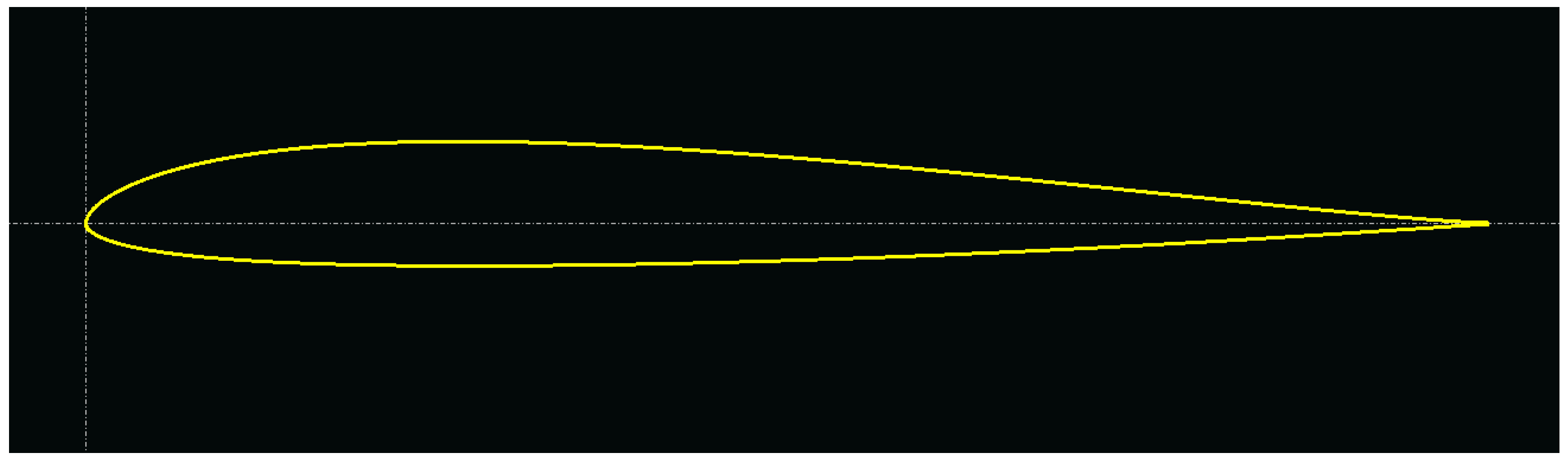
| Ref. wing area | 0.436 m2 | Airfoil | PW-51 |
| Dihedral | 5o | Aspect ratio | 4.291 |
Disclaimer/Publisher’s Note: The statements, opinions and data contained in all publications are solely those of the individual author(s) and contributor(s) and not of MDPI and/or the editor(s). MDPI and/or the editor(s) disclaim responsibility for any injury to people or property resulting from any ideas, methods, instructions or products referred to in the content. |
© 2023 by the authors. Licensee MDPI, Basel, Switzerland. This article is an open access article distributed under the terms and conditions of the Creative Commons Attribution (CC BY) license (https://creativecommons.org/licenses/by/4.0/).
Share and Cite
Ozbek, E.; Ekici, S.; Karakoc, T.H. Unleashing the Potential of Morphing Wings: A Novel Cost Effective Morphing Method for UAV Surfaces, Rear Spar Articulated Wing Camber. Drones 2023, 7, 379. https://doi.org/10.3390/drones7060379
Ozbek E, Ekici S, Karakoc TH. Unleashing the Potential of Morphing Wings: A Novel Cost Effective Morphing Method for UAV Surfaces, Rear Spar Articulated Wing Camber. Drones. 2023; 7(6):379. https://doi.org/10.3390/drones7060379
Chicago/Turabian StyleOzbek, Emre, Selcuk Ekici, and T. Hikmet Karakoc. 2023. "Unleashing the Potential of Morphing Wings: A Novel Cost Effective Morphing Method for UAV Surfaces, Rear Spar Articulated Wing Camber" Drones 7, no. 6: 379. https://doi.org/10.3390/drones7060379